EP1740414B1 - Method and apparatus for detecting and correcting trailer induced yaw movements in a towing vehicle - Google Patents
Method and apparatus for detecting and correcting trailer induced yaw movements in a towing vehicle Download PDFInfo
- Publication number
- EP1740414B1 EP1740414B1 EP04777053.2A EP04777053A EP1740414B1 EP 1740414 B1 EP1740414 B1 EP 1740414B1 EP 04777053 A EP04777053 A EP 04777053A EP 1740414 B1 EP1740414 B1 EP 1740414B1
- Authority
- EP
- European Patent Office
- Prior art keywords
- towing vehicle
- yaw rate
- vehicle
- yaw
- control unit
- Prior art date
- Legal status (The legal status is an assumption and is not a legal conclusion. Google has not performed a legal analysis and makes no representation as to the accuracy of the status listed.)
- Expired - Lifetime
Links
- 230000033001 locomotion Effects 0.000 title claims description 55
- 238000000034 method Methods 0.000 title claims description 9
- 230000001934 delay Effects 0.000 claims description 2
- 238000012544 monitoring process Methods 0.000 claims 1
- 238000004422 calculation algorithm Methods 0.000 description 44
- 230000009471 action Effects 0.000 description 12
- 230000006870 function Effects 0.000 description 12
- 238000010586 diagram Methods 0.000 description 9
- 238000001514 detection method Methods 0.000 description 6
- 238000009795 derivation Methods 0.000 description 5
- 239000012530 fluid Substances 0.000 description 4
- 230000001133 acceleration Effects 0.000 description 3
- 238000000586 desensitisation Methods 0.000 description 3
- 230000004913 activation Effects 0.000 description 2
- 238000004364 calculation method Methods 0.000 description 2
- 230000000694 effects Effects 0.000 description 2
- 230000005484 gravity Effects 0.000 description 2
- 230000009467 reduction Effects 0.000 description 2
- 239000002826 coolant Substances 0.000 description 1
- 238000001816 cooling Methods 0.000 description 1
- 230000001419 dependent effect Effects 0.000 description 1
- 230000009977 dual effect Effects 0.000 description 1
- 230000001939 inductive effect Effects 0.000 description 1
- 230000010354 integration Effects 0.000 description 1
- 238000012886 linear function Methods 0.000 description 1
- 239000010687 lubricating oil Substances 0.000 description 1
- 238000002360 preparation method Methods 0.000 description 1
- 230000004044 response Effects 0.000 description 1
- 230000000087 stabilizing effect Effects 0.000 description 1
Images





Classifications
-
- B—PERFORMING OPERATIONS; TRANSPORTING
- B60—VEHICLES IN GENERAL
- B60T—VEHICLE BRAKE CONTROL SYSTEMS OR PARTS THEREOF; BRAKE CONTROL SYSTEMS OR PARTS THEREOF, IN GENERAL; ARRANGEMENT OF BRAKING ELEMENTS ON VEHICLES IN GENERAL; PORTABLE DEVICES FOR PREVENTING UNWANTED MOVEMENT OF VEHICLES; VEHICLE MODIFICATIONS TO FACILITATE COOLING OF BRAKES
- B60T8/00—Arrangements for adjusting wheel-braking force to meet varying vehicular or ground-surface conditions, e.g. limiting or varying distribution of braking force
- B60T8/17—Using electrical or electronic regulation means to control braking
- B60T8/1701—Braking or traction control means specially adapted for particular types of vehicles
- B60T8/1708—Braking or traction control means specially adapted for particular types of vehicles for lorries or tractor-trailer combinations
-
- B—PERFORMING OPERATIONS; TRANSPORTING
- B60—VEHICLES IN GENERAL
- B60T—VEHICLE BRAKE CONTROL SYSTEMS OR PARTS THEREOF; BRAKE CONTROL SYSTEMS OR PARTS THEREOF, IN GENERAL; ARRANGEMENT OF BRAKING ELEMENTS ON VEHICLES IN GENERAL; PORTABLE DEVICES FOR PREVENTING UNWANTED MOVEMENT OF VEHICLES; VEHICLE MODIFICATIONS TO FACILITATE COOLING OF BRAKES
- B60T8/00—Arrangements for adjusting wheel-braking force to meet varying vehicular or ground-surface conditions, e.g. limiting or varying distribution of braking force
- B60T8/17—Using electrical or electronic regulation means to control braking
- B60T8/1755—Brake regulation specially adapted to control the stability of the vehicle, e.g. taking into account yaw rate or transverse acceleration in a curve
-
- G—PHYSICS
- G05—CONTROLLING; REGULATING
- G05D—SYSTEMS FOR CONTROLLING OR REGULATING NON-ELECTRIC VARIABLES
- G05D1/00—Control of position, course, altitude or attitude of land, water, air or space vehicles, e.g. using automatic pilots
- G05D1/08—Control of attitude, i.e. control of roll, pitch, or yaw
- G05D1/0891—Control of attitude, i.e. control of roll, pitch, or yaw specially adapted for land vehicles
-
- B—PERFORMING OPERATIONS; TRANSPORTING
- B60—VEHICLES IN GENERAL
- B60T—VEHICLE BRAKE CONTROL SYSTEMS OR PARTS THEREOF; BRAKE CONTROL SYSTEMS OR PARTS THEREOF, IN GENERAL; ARRANGEMENT OF BRAKING ELEMENTS ON VEHICLES IN GENERAL; PORTABLE DEVICES FOR PREVENTING UNWANTED MOVEMENT OF VEHICLES; VEHICLE MODIFICATIONS TO FACILITATE COOLING OF BRAKES
- B60T2230/00—Monitoring, detecting special vehicle behaviour; Counteracting thereof
- B60T2230/06—Tractor-trailer swaying
Definitions
- This invention relates in general to vehicle stability control systems and in particular to detection and correction of vehicle vaw movement while the vehicle is towing a trailer.
- German Patent Application DE 100 48 418 discloses analyzing for a critical frequency of vehicular yaw.
- the article Aktive Gespannstabilmaschine Institut BMW X5 discloses determining when to apply braking based upon yaw amplitude.
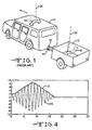
- FIG. 1 A typical vehicle 10 towing a trailer 12 is illustrated in Fig. 1 .
- the towing vehicle 10 is equipped with a trailer hitch 14 that is connected to a trailer tongue 16 that extends from the front of the trailer 12.
- trailers with four or more wheel usually mounted upon multiple axles are also common.
- trailers with four or more wheel usually mounted upon multiple axles are also common.
- light trailers do not have trailer brakes and are dependent upon the towing vehicle brakes for slowing and stopping.
- heavier trailers such as camper trailers are often equipped with electric or hydraulic brake systems.
- trailers are totally controlled by the towing vehicle. Outside factors, such as loading, speed, road conditions, cross winds and movement of the towing vehicle can induce unwanted motions in a trailer.
- unwanted motions is rotation, or yaw motion, as represented by the double headed arrow labeled 18 in Fig. 1 , about a vertical axis 20 that passes through the center of gravity of the trailer 12.
- Such yaw motions tend to increase with speed and are transferred through the trailer tongue 16 and hitch 14 to the towing vehicle 10 where similar yaw motions, as represented by the double headed arrow labeled 22, may be induced about a vertical axis 24 passing through the center of gravity of the towing vehicle 10.
- the yaw motions of the towing vehicle 10 can develop quite suddenly and, if the vehicle operator does not react quickly, and correctly, can result in loss of directional control of the towing vehicle.
- An improper response by the towing vehicle operator to trailer induced yaw motions can actually exacerbate the yaw motions.
- the combination of the trailer 12 and vehicle 10 may jackknife, run off the road, or cross into the opposing traffic lane. Any of these results are most unsatisfactory.
- trailers are typically not equipped to detect yaw motion.
- This invention relates to detection and correction of vehicle yaw movement while the vehicle is towing a trailer.
- the present invention contemplates an apparatus for detecting excessive yaw motions induced in a towing vehicle by a towed trailer that includes a plurality of vehicle parameter sensors adapted to be mounted upon the towing vehicle and an electronic control unit also adapted to be mounted upon the towing vehicle.
- the electronic control unit is electrically connected to the towing vehicle parameter sensors and is responsive to signals received from the vehicle parameter sensors to calculate an instability index for the towing vehicle that is a function of the towing vehicle yaw rate.
- the electronic control unit Upon the towing vehicle instability index exceeding a predetermined instability threshold, the electronic control unit generates an excessive yaw motion signal, which in the preferred embodiment, causes an instability flag to be set.
- the invention further contemplates that the electronic control unit is operable to determine an intended maximum yaw rate curve and an actual towing vehicle maximum yaw rate curve.
- the electronic control unit being further operable to determine the instability index as a function of the difference between the intended maximum yaw rate curve and the actual towing vehicle maximum yaw rate curve.
- the vehicle parameter sensors include a steering angle sensor and a plurality of wheel speed sensors adapted to be mounted upon the towing vehicle.
- the electronic control unit is responsive to signals received from the steering angle sensor and the wheel speed sensors to calculate a driver intended yaw rate and then use the driver intended yaw rate to calculate the intended maximum yaw rate curve.
- the towing vehicle parameter sensors include a yaw rate sensor adapted to mounted upon the towing vehicle with the yaw rate sensor generating a signal that is proportional to the actual towing vehicle yaw rate.
- the electronic control unit being responsive to the actual towing vehicle yaw rate to calculate the actual towing vehicle maximum yaw rate curve.
- the excessive towing vehicle yaw rate detection apparatus may be included in a vehicle stability control system that would be responsive to the excessive yaw rate signal to selectively apply the towing vehicle brakes to reduce the excessive yaw rate.
- the present invention also contemplates a method for detecting excessive yaw motions induced in a towing vehicle by a towed trailer that includes the steps of providing a plurality of vehicle parameter sensors adapted to be mounted upon the towing vehicle and an electronic control unit also adapted to be mounted upon the towing vehicle.
- the electronic control unit is electrically connected to the vehicle parameter sensors and monitors the vehicle parameter sensors and uses the sensor output signals to determine an instability index for the towing vehicle that is a function of the towing vehicle yaw rate.
- the electronic control unit compares the instability index to a predetermined instability threshold.
- the electronic control unit upon determining that the instability index exceeds the predetermined instability threshold, the electronic control unit generates an excessive yaw motion signal, which in the preferred embodiment, causes an instability flag to be set.
- the apparatus can be included in an electronic brake control system and that the method further includes, subsequent to the instability flag being set, a step of selectively applying the towing vehicle brakes to reduce the yaw motion of the towing vehicle.
- Fig. 1 is Fig. 1 is perspective view of a vehicle towing a trailer.
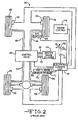
- Fig. 2 is a schematic diagram of a typical vehicle stability control system
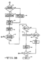
- Fig. 3 is a flow chart for an algorithm for detecting and correcting trailer yaw motion that is accordance with the present invention.
- Fig. 4 illustrates a max yaw rate curve utilized in the present invention.
- Fig. 5 is a block diagram that illustrates the derivation of an intended vehicle yaw rate max curve.
- Fig. 6 is a block diagram that illustrates the derivation of an actual vehicle yaw rate max curve.
- Fig. 7 is a block diagram that illustrates the derivation of an instability indicator from the yaw max rate curves derived from Figs. 5 and 6 .
- Fig. 8 illustrates typical signals generated by the components shown in Fig. 7 .
- Fig. 9 illustrates typical frequencies associated with the actual vehicle yaw signal.
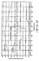
- Fig. 10 illustrates various vehicle parameters during an application of the towing vehicle rear brakes to correct of excessive towing vehicle yaw motions.
- Fig. 11 illustrates an alternate towing vehicle braking action to correct excessive trailer yaw motions where the towing vehicle has a diagonally split brake system.
- Fig. 12 illustrates another alternate towing vehicle braking action to correct excessive trailer yaw motions where the towing vehicle has a vertically split brake system.
- the present invention contemplates using the components available in a Vehicle Stability Control (VSC) system to detect and correct unwanted yaw motions in a towed trailer.
- VSC Vehicle Stability Control
- Fig. 2 a schematic diagram of a typical VSC system 30.
- the VSC system 30 is operative to detect deviations in moving vehicle direction from the direction desired and to selectively apply the vehicle wheel brakes to correct the deviation. While a rear wheel drive vehicle is illustrated in Fig. 2 , it will be appreciated that VSC systems also are available for front wheel drive and four wheel drive vehicles.
- the system 30 is intended to be exemplary and it will be appreciated that there are other brake control systems having more or less components.
- the VSC system 30 includes a brake pedal 32 that is mechanically connected, as indicated by the dashed lines, to a brake light switch 33 and a dual reservoir master cylinder 34.
- a first reservoir of the master cylinder 34 supplies hydraulic fluid to a front wheel brake circuit while a second reservoir provides hydraulic brake fluid to a rear wheel brake circuit.
- the brake system illustrated in Fig. 2 is vertically split; however, it will be appreciated that the invention also may practiced upon other brake system configurations, such as for example, a diagonally split brake system.
- the first master cylinder reservoir supplies the left front and right rear wheel brakes while the second master cylinder reservoir supplies the right front and left rear wheel brakes.
- the master cylinder first reservoir is connected to an VSC control valve 36 by a first hydraulic line 38 while the second reservoir is connected to the control valve 36 by a second hydraulic line 40.
- the VSC control valve 36 includes a plurality of normally open and normally closed solenoid valves (not shown) and a separate source of pressurized hydraulic fluid, such as a motor driven pump (not shown).
- the pump is typically included within the body of the control valve 36 while the pump motor is mounted upon the exterior thereof.
- the control valve 36 is connected by a first pair of hydraulic brake lines 42 and 44 to wheel brakes (not shown) for the left and right front vehicle wheels 46 and 48, respectively.
- the front wheels 46 and 48 are non-driven but steerable.
- a second pair of hydraulic brake lines 50 and 52 connect the control valve 36 to wheel brakes (not shown) for the left and right rear vehicle wheels 54 and 56, respectively.
- the speed of the front wheels 46 and 48 are monitored by a first pair of wheel associated wheel speed sensors, 58 and 60, respectively. Similarly, the speed of the rear wheels 54 and 56 are monitored by a second pair of associated wheel speed sensors 62 and 64, respectively.
- the wheel speed sensors 46, 48, 62 and 64 are electrically connected to an VSC Electronic Control Unit (ECU) 66.
- the ECU 66 also is electrically connected to the bake light switch 33. Closing the brake switch 33 provides a signal to the ECU 66 that the vehicle brakes have been activated.
- the ECU 66 also is electrically connected to the pump motor and the actuation coils of the solenoid valves included with the control valve 36.
- the ECU 66 is further electrically connected to several sensors that monitor the dynamics of the towing vehicle 10.
- One of the sensors is a steering angle sensor 68 that generates a signal that is proportional to the steering angle of the front wheels 46 and 48.
- the system 30 also includes a vehicle yaw sensor 70 for measuring vehicle yaw motion and an accelerometer 72 for measuring vehicle lateral acceleration. Both the vehicle yaw sensor 70 and the accelerometer 72 are electrically connected to the ECU 66. Alternately, the wheel speeds may be utilized to calculate a vehicle acceleration, in which case the accelerometer 72 may be omitted.
- the ECU also is electrically connected to an engine controller 74.
- the ECU 66 receives engine speed signals from the engine controller 74 and is operative to send control signals to the engine controller 74 for changing the engine torque.
- the ECU 66 further includes a microprocessor with a memory that stores a VSC control algorithm.
- the microprocessor in the ECU 38 continuously receives speed signals from the wheel speed sensors 58, 60, 62 and 64. Additionally, the microprocessor receives input signals from the steering angle sensor 68, the yaw sensor 70, the accelerometer 70 and the engine controller 74.
- the ECU microprocessor is operative to detect any excessive deviation of the vehicle direction from the desired vehicle direction.
- the ECU 66 is responsive to the excessive deviation to selectively operate the solenoid valves in the control valve 36 to apply the vehicle wheel brakes to generate a counter brake torque to correct the directional deviation. Thus, if the vehicle 10 begins to bear excessively left, one or both of the right wheel brakes are applied to cause a braking moment to swing the vehicle 10 to the right.
- the ECU 66 also can send a control signal to the engine controller 74 to reduce the engine torque. While the system 30 has been described in terms of VSC, the components also can be utilized, with the appropriate control algorithm, to provide Traction Control (TC) and Anti-lock Brake Control (ABC) functions for the towing vehicle 10.
- TC Traction Control
- ABS Anti-lock Brake Control
- the present invention contemplates an ECU control algorithm that utilizes the components of the VSC system 30 shown in Fig. 2 to determine that a towing vehicle 10 is experiencing excessive yaw motions induced by a towed trailer 12.
- the invention also contemplates that the algorithm is responsive to excessive towing vehicle yaw motions to selectively apply the towing vehicle wheel brakes to reduce or eliminate the vehicle yaw motions.
- the invention further contemplates combining the braking with engine torque reduction.
- FIG. 3 An overall flow chart for the yaw detection and reduction algorithm is illustrated in Fig. 3 .
- the flow chart is entered through block 80 and proceeds to decision block 81 where the algorithm determines whether the vehicle ignition is in the on position. If the ignition is not in the on position, the algorithm returns to block 80. If the ignition is in the on position, the algorithm advances to functional block 82 where the microprocessor in the ECU 66 receives signals from the vehicle sensors. These sensor signals include wheel speed signals from the wheel speed sensors 58, 60, 62 and 64. The microprocessor also receives steering direction data from the steering angle sensor 68 and engine speed data from the engine controller 74. Vehicle motion data is received by the microprocessor from the vehicle yaw sensor 70 and the acceleration sensor 72.
- control mode is normal and the sensor signals are initialized. If the control mode is normal and the sensor signals are initialized the algorithm continues to functional block 84 where the data received from the sensors are prepared for utilization in the calculations in the following functional blocks. If control mode is not normal and the sensor signals are not initialized in decision block 83, the algorithm returns to functional block 82.
- the algorithm advances to functional block 85 where a maximum curve of a driver intended yaw rate, Rlin, is determined. The determination of the Rlin maximum curve is illustrated in Fig. 5 and explained in detail below.
- the algorithm continues to functional block 86 where a maximum curve of the towing vehicle yaw rate is determined. The determination of the yaw rate maximum curve is illustrated in Fig. 6 and explained in detail below.
- the algorithm then continues to functional block 87 where the towing vehicle yaw rate frequency is determined.
- the algorithm advances functional block 88 where a desensitization factor that is a function of the instantaneous driver intended yaw rate is determined.
- an instability index V INS is determined as a function of the Rlin maximum curve, the yaw rate maximum curve and the desensitization factor as determined in preceding functional blocks 85, 86 and 88, respectively.
- the determination of V INS is illustrated in Fig. 7 and explained in detail below.
- the instability index is a sum of proportional, integral and derivative terms.
- decision block 90 the towing vehicle speed is compared to a predetermined reset speed and the instability index V INS determined in functional block 89 is compared to an instability index minimum threshold. If either the towing vehicle speed is less than the reset speed or the instability index is less than the instability index minimum threshold, the algorithm transfers to functional block 91. In functional block 91 the proportional, integral and derivative terms of the instability index V INS are reset. The algorithm then advances to decision block 92. If, in decision block 90, the towing vehicle speed is greater than, or equal to, the reset speed and the instability index is also greater than, or equal to, the instability index minimum threshold, the algorithm advances directly to decision block 92.
- the actual towing vehicle yaw rate frequency is compared to a frequency range that is a function of the actual towing vehicle yaw rate magnitude.
- the lower limit, f 1 on the frequency range is 0.4 Hz
- the upper limit, f 2 is 1.1 Hz; however, other values for the frequency range bounds also may be used.
- the algorithm transfers to functional block 93 where the proportional and integral terms and a negative derivative term of the instability V INS index are calculated.
- the algorithm then continues to functional block 94. Should the vehicle yaw frequency fall outside of the frequency range in decision block 92, the algorithm transfers to functional block 95 where the proportional and derivative terms of the instability index are reset and the algorithm ramps out of the integral term.
- the algorithm then continues to functional block 94.
- the instability index is passed through a low pass filter.
- the algorithm then advances to functional block 96 where a deceleration request is determined for potential use as a corrective action.
- the algorithm then continues to decision block 97.
- decision block 97 it is determined whether actual the towing vehicle speed V S is greater than a minimum speed threshold, T MIN . If the towing vehicle speed is less than, or equal to T MIN , the algorithm returns to functional block 82 for the next iteration. Also, the algorithm is not intended for use when the towing vehicle 10 and trailer are backing. Accordingly, the direction of movement of the towing vehicle also is checked in decision block 97. If the towing vehicle 10 is moving in reverse in decision block 97, the algorithm returns to functional block 82 for the next iteration. Only if the towing vehicle is not in reverse and the towing vehicle speed is above T MIN in decision block 87, does the algorithm transfer to decision block 98.
- T MIN minimum speed threshold
- the towing vehicle instability index V INS is compared to a first excessive yaw threshold, T 1 . If the towing vehicle instability index V INS is greater than the first excessive yaw threshold T 1 , the algorithm determines that the trailer 12 is experiencing excessive yaw movement and advances to decision block 99 where a trailer yaw flag is set to activate corrective action. The algorithm then advances to functional block 100 where one or more available corrective actions are applied to the towing vehicle 10 to reduce and/or eliminate the trailer yaw motion. Various possible correction actions are described below. The algorithm then continues to decision block 101.
- the algorithm transfers to decision block 102 where the instability index is compared to a second excessive yaw threshold, T 2 , that is less than the first excessive yaw threshold T 1 .
- the second excessive yaw threshold T 2 is selected to be less than the first excessive yaw threshold T 1 to introduce hysteresis and thereby avoid "hunting" within the algorithm. If, in decision block 102, the instability index has fallen below the second excessive yaw threshold T 2 , the algorithm advances to functional block 103 where the trailer yaw flag is reset. The algorithm then advances to decision block 101.
- decision block 101 the vehicle status is compared to an algorithm end criteria. As shown in Fig. 3 , the algorithm ends when the vehicle ignition switch has been returned to the off position. If the vehicle ignition switch has not been returned to the off position, the algorithm returns to functional block 82 for the next iteration. If the vehicle ignition switch has been returned to the off position in decision block 101, the algorithm exits through bock 104.
- the invention also contemplates several additional optional criteria that are not shown in Fig. 3 .
- the invention also may be practiced with a requirement that yaw frequency rate remain within the frequency range for a predetermined time period before the corrective action is applied.
- a timer loop (not shown) between decision block 92 and decision block 93.
- the invention may also require that the towing vehicle speed remain above the minimum speed threshold T MIN for a predetermined time period before the corrective action is applied.
- Such a feature could be implemented by adding a timer loop (not shown) after decision block 97. While decision block 97 requires that the vehicle not be moving in reverse, an alternate version would require that the vehicle be moving in the forward direction (not shown) before proceeding.
- the determination of the presence of excessive yaw motion in a vehicle towing a trailer is determined by a comparison in decision block 98 between an instability index and the first excessive yaw threshold T 1 .
- the calculation of the instability index V INS will now be described with reference to Figs. 4 through 7 .
- the instability index V INS is a function of the difference between a maximum curve for the towing vehicle yaw rate, or yaw rate feedback, and a maximum curve for driver intended yaw rate, Rlin. A typical such maximum yaw rate curve is illustrated in Fig.
- the increasing and then damped sinusoidal curve labeled 110 represents either the instantaneous driver intended vehicle yaw rate or the yaw rate feedback.
- the maximum yaw rate curve labeled 112 and each of the steps comprising the curve represents the absolute value of the maximum magnitude of each of the excursions of the instantaneous yaw rate curve 110.
- FIG. 5 A block diagram that illustrates the derivation of the driver intended vehicle yaw rate maximum curve is shown in Fig. 5 .
- the factor Rlin represents the driver intended yaw rate that is obtained from the steering angle sensor data and the vehicle speed.
- a derivative of the absolute valve of the yaw rate is filtered and then compared to a previous value to find a peak. The peak is then used with the absolute value of the yaw rate to calculate a current value for the intended vehicle yaw rate maximum curve.
- a block diagram that illustrates the derivation of the actual vehicle yaw rate maximum curve is shown in Fig. 6 and includes steps similar to the steps described above for Fig. 5 to convert ⁇ into the actual vehicle yaw rate maximum curve.
- the factor ⁇ represents the actual vehicle yaw rate that is obtained from the vehicle yaw rate sensor 70. Because the actual vehicle yaw rate is compared to the driver intended vehicle yaw rate, the actual vehicle yaw rate can be considered as a feedback yaw rate, as shown at the right side of Fig. 6 .
- the yaw rate maximum curves derived as shown in Figs. 5 and 6 are combined and an instability index V INS determined in the block diagram illustrated in Fig. 7 .
- the maximum driver intended yaw rate curve derived in functional block 85 of Fig. 3 is subtracted from the maximum actual yaw rate, or feedback yaw rate, curve derived in functional block 86 of Fig. 3 , as shown in Fig. 6 .
- the resulting difference is first passed through a low pass filter 132 and then through a rise and decay limiter 134.
- a control offset, or driver input desensitization that is a function of the instantaneous driver intended yaw rate and is determined in functional block 88 of Fig. 3 , is added to the signal at the summing point labeled 136.
- the resulting signal is then operated upon by three different operators in the right portion of Fig. 7 .
- the signal is multiplied by a proportionality constant KD in the block labeled 138.
- the resulting proportional term is passed through a first limiter 140 that keeps the result within upper and lower limits.
- the derivative of the signal is taken in the block labeled 142.
- the resulting derivative term is multiplied by a differential constant KD in block 144 and then passed through a second limiter 146.
- the signal is integrated at 148 and the integral term is multiplied by a integrator constant KI.
- the signal is then passed through a third limiter 150.
- the resulting three terms are combined at the summing point at the right end of Fig. 7 that is labeled 152 to produce the stability indicator V INS .
- the stability indicator V INS is compared to the first stability activation threshold T 1 in decision block 98 in Fig. 3 .
- Typical curves for the values determined within the block diagram shown in Fig. 7 are illustrated in Fig. 8 .
- the lower curve 160 in Fig. 8 represents the filtered and limited difference, or error, between the intended and actual, or feedback, yaw rate maximum curves as derived in the left portion of Fig. 7 .
- the middle set of three curves represents the values derived in the right portion of Fig. 7 .
- the lowest curve in the middle set of curves is labeled 162 and represents the differential term resulting from the differential operator 142 shown in the middle operation at the right of Fig. 7 .
- the middle curve in the set of curves, which is labeled 164 represents the integral term resulting from the integration operator 148 shown in the lower operation of Fig. 7 .
- the upper curve in the set of curves which is labeled 166, represents the proportional term resulting from the proportional operator 138 shown in the upper operation of Fig. 7 .
- the uppermost curve in Fig. 8 which is labeled 168 is the sum of the three curves 162, 164 and 166 shown below it and thus represents the instability index V INS , which is a PID output signal.
- the negative differential part of the PID signal prevents a falsely detected yaw error from causing activation of trailer yaw correction actions.
- the frequency associated with the PID signal in Fig. 8 is illustrated in Fig. 9 .
- the control algorithm continuously determines the frequency of the actual vehicle yaw raw.
- the peak yaw rate flag shown in Fig. 9 represents the local maximum of the actual vehicle yaw rate.
- one of the criteria for determining that the trailer yaw rate motions are excessive is that the actual vehicle yaw rate frequency is within a predetermined frequency range that is a function of the actual yaw rate magnitude.
- the first type of corrective measure includes deceleration of the vehicle and trailer by applying only the towing vehicle brakes.
- the braking can accomplished by actuating only the rear wheel brakes, only the front wheel brakes, or both the front and rear wheel brakes.
- the rear wheel brakes are preferred over the front wheel brakes.
- the towing vehicle brakes are applied to provide a deceleration rate that is within the range of 1.0 to 7.0 meters/second 2 ; however, other deceleration rates may also be used.
- the deceleration rate may be selected to be within the range of 1.5 to 5.0 meters/second 2 .
- the ECU 66 may send a control signal, as determined in functional block 96 of Fig. 3 , to the engine controller 74 to reduce the towing vehicle engine torque.
- An example of trailer yaw motion control by application of the towing vehicle wheel brakes is illustrated by the graphs shown in Fig. 10 .
- the graphs show that, as the vehicle speed increases, actual towing vehicle yaw motions induced by the trailer develop and diverge from the driver intended yaw rate.
- the trailer brakes are then actuated.
- the towing vehicle 10 and trailer 12 are decelerated at a constant rate of 1.2 meters/second 2 . As the vehicle and trailer slow, the actual yaw rate excursions are reduced until they again approximate the driver intended yaw rate curve.
- the invention contemplates using two deceleration rates with the selected deceleration rate being determined by the magnitude of the instability index V INS .
- the instability index V INS exceeds the first instability threshold T 1
- the ECU is responsive to apply a medium deceleration to counter the vehicle yaw motios.
- Typical medium deceleration rates may be within a range 4.0 to 5.0 meters/second 2 .
- the instability index V INS drops below the first instability threshold T 1 , but still exceeds the instability threshold T 2
- the ECU 66 is responsive to apply a low deceleration to counter the vehicle yaw motions.
- Typical low deceleration rates may be within a range 1.0 to 3.0 meters/second 2 .
- the invention also contemplates another alternate embodiment where the deceleration rate applied to the vehicle brakes is continuously variable as a function of one or more vehicle parameter (not shown).
- the deceleration may be either a linear or non-linear function of the towing vehicle speed.
- a second type of corrective measure contemplated by the invention applies to a vehicle towing a trailer that is equipped with trailer brakes.
- the trailer brakes would typically be actuated by a trailer brake control unit upon detection of vehicle deceleration.
- the trailer is braked with a slightly higher deceleration rate than that of the towing vehicle. For example, if the towing vehicle is braked at 2.0 meters/second 2 the trailer could be braked at 2.0 meters/second 2 + an offset, such as, for example, an offset selected from within a range of 0.2 to 0.5 meters/second 2 .
- the offset could be either programmed into the trailer brake controller or supplied independently to the trailer brakes by the ECU 66.
- a third type of corrective measure would also apply to a trailer equipped with trailer brakes.
- the third corrective measure contemplates deceleration of the towing vehicle as described above combined with an independent trailer brake application to generate a counter brake torque in opposition to the trailer yaw motions.
- the left trailer brake would be applied to swing the trailer back to the right.
- a fourth type of corrective measure is contemplated in which the trailer brakes are applied to provide a counter brake torque in opposition to the trailer yaw motions.
- the fourth corrective measure can be applied to only the towing vehicle brakes or, if the trailer is equipped with brakes, in combination with a trailer brake application.
- An example of the fourth type of corrective measure is illustrated in Fig. 11 where the pressure of the hydraulic fluid at each of the towing vehicle wheel brakes is shown as a function of time for a diagonally split towing vehicle brake system. As shown in Fig. 11 , a constant brake pressure is applied to all of the towing vehicle wheel brakes at t 1 to slow both the towing vehicle 10 and trailer 12.
- Additional pressure is applied to the right rear and left front wheel brakes to generate a yaw countering brake torque.
- the additional pressure is modulated in magnitude and timing in approximate phase with the vehicle yaw rate, as shown in Fig. 11 to oppose the trailer induced vehicle yaw motions.
- the resulting induced brake torque would tend to swing the towing vehicle 10 to the right.
- a similar additional pressure modulation is applied to the right front and left rear wheel brakes, again in approximate phase with the vehicle yaw rate.
- This corrective measure allows the towing vehicle operator to apply additional pressure to the towing vehicle brakes while the measure is being applied or to brake through a traction or vehicle stability control cycle.
- the brake pressure modulation also may be applied to only the front wheel brakes or to only the rear wheel brakes of the towing vehicle 10.
- the resulting brake torque is less than that obtained by modulating the it must be pressure applied to all four of the towing vehicle wheel brakes.
- This corrective measure also allows the towing vehicle operator to apply additional pressure to the towing vehicle brakes while the measure is being applied or to brake through a traction or vehicle stability control cycle.
- FIG. 12 An alternate embodiment of the fourth type of corrective action is illustrated in Fig. 12 for a vertically split brake system. Again, the corrective action is initiated at t 1 . As shown in Fig. 12 , while all four wheel brakes are applied, only the rear wheel brakes are modulated with extra pressure. Similarly, the invention also may be practiced with a vertically split brake system in which all four wheel brakes are applied, but only the front wheel brakes are modulated with extra pressure (not shown).
- the invention further contemplates another alternate embodiment in which the towing vehicle and trailer yaw movements are monitored to determine an optimal time for applying the brakes.
- the control unit delays the brake application until both the instability factor exceeds the first excessive yaw threshold T 1 and the optimum moment for inducing a stabilizing brake moment has arrived.
Landscapes
- Engineering & Computer Science (AREA)
- Transportation (AREA)
- Mechanical Engineering (AREA)
- Aviation & Aerospace Engineering (AREA)
- Radar, Positioning & Navigation (AREA)
- Remote Sensing (AREA)
- Physics & Mathematics (AREA)
- General Physics & Mathematics (AREA)
- Automation & Control Theory (AREA)
- Regulating Braking Force (AREA)
- Control Of Driving Devices And Active Controlling Of Vehicle (AREA)
Description
- This invention relates in general to vehicle stability control systems and in particular to detection and correction of vehicle vaw movement while the vehicle is towing a trailer.
- German
Patent Application DE 100 48 418 discloses analyzing for a critical frequency of vehicular yaw. Similarly, the article Aktive Gespannstabilisierung beim BMW X5 discloses determining when to apply braking based upon yaw amplitude. - With the increasing popularity of recreational activities such as boating, snowmobiling and similar activities, the need to tow trailers for transporting recreational equipment is increasing. Additionally, many motorists have access to light utility trailers for hauling items. The increasing need to tow trailers has been noted and vehicle manufactures have responded by marketing pickup trucks and sport utility vehicles equipped with trailer towing packages that can include a trailer hitch, a wiring harness and connector for the trailer brake lights and additional cooling capacity for the engine coolant and lubricating oil. A
typical vehicle 10 towing atrailer 12 is illustrated inFig. 1 . Thetowing vehicle 10 is equipped with atrailer hitch 14 that is connected to atrailer tongue 16 that extends from the front of thetrailer 12. While atrailer 12 having two wheels is shown, trailers with four or more wheel, usually mounted upon multiple axles are also common. Typically, light trailers do not have trailer brakes and are dependent upon the towing vehicle brakes for slowing and stopping. However, heavier trailers, such as camper trailers are often equipped with electric or hydraulic brake systems. - Due to their nature, trailers are totally controlled by the towing vehicle. Outside factors, such as loading, speed, road conditions, cross winds and movement of the towing vehicle can induce unwanted motions in a trailer. Among such unwanted motions, is rotation, or yaw motion, as represented by the double headed arrow labeled 18 in
Fig. 1 , about avertical axis 20 that passes through the center of gravity of thetrailer 12. Such yaw motions tend to increase with speed and are transferred through thetrailer tongue 16 and hitch 14 to thetowing vehicle 10 where similar yaw motions, as represented by the double headed arrow labeled 22, may be induced about avertical axis 24 passing through the center of gravity of thetowing vehicle 10. - The yaw motions of the
towing vehicle 10 can develop quite suddenly and, if the vehicle operator does not react quickly, and correctly, can result in loss of directional control of the towing vehicle. An improper response by the towing vehicle operator to trailer induced yaw motions can actually exacerbate the yaw motions. In an extreme situation, the combination of thetrailer 12 andvehicle 10 may jackknife, run off the road, or cross into the opposing traffic lane. Any of these results are most unsatisfactory. Additionally, trailers are typically not equipped to detect yaw motion. Accordingly, it would be desirable to be able to detect the development of yaw motions in a towing vehicle sufficiently in advance of a directional stability problem developing to allow time for the vehicle operator to take corrective actions. It also would be desirable to provide such detection by utilizing components already present upon the towing vehicle. It would be further desirable to use brake control systems present upon the vehicle to correct the trailer induced towing vehicle yaw motions before directional control problems develop. - This invention relates to detection and correction of vehicle yaw movement while the vehicle is towing a trailer.
- The present invention contemplates an apparatus for detecting excessive yaw motions induced in a towing vehicle by a towed trailer that includes a plurality of vehicle parameter sensors adapted to be mounted upon the towing vehicle and an electronic control unit also adapted to be mounted upon the towing vehicle. The electronic control unit is electrically connected to the towing vehicle parameter sensors and is responsive to signals received from the vehicle parameter sensors to calculate an instability index for the towing vehicle that is a function of the towing vehicle yaw rate. Upon the towing vehicle instability index exceeding a predetermined instability threshold, the electronic control unit generates an excessive yaw motion signal, which in the preferred embodiment, causes an instability flag to be set.
- The invention further contemplates that the electronic control unit is operable to determine an intended maximum yaw rate curve and an actual towing vehicle maximum yaw rate curve. The electronic control unit being further operable to determine the instability index as a function of the difference between the intended maximum yaw rate curve and the actual towing vehicle maximum yaw rate curve. The invention also contemplates that the vehicle parameter sensors include a steering angle sensor and a plurality of wheel speed sensors adapted to be mounted upon the towing vehicle. The electronic control unit is responsive to signals received from the steering angle sensor and the wheel speed sensors to calculate a driver intended yaw rate and then use the driver intended yaw rate to calculate the intended maximum yaw rate curve. Additionally, the towing vehicle parameter sensors include a yaw rate sensor adapted to mounted upon the towing vehicle with the yaw rate sensor generating a signal that is proportional to the actual towing vehicle yaw rate. The electronic control unit being responsive to the actual towing vehicle yaw rate to calculate the actual towing vehicle maximum yaw rate curve.
- It is further contemplated that the excessive towing vehicle yaw rate detection apparatus may be included in a vehicle stability control system that would be responsive to the excessive yaw rate signal to selectively apply the towing vehicle brakes to reduce the excessive yaw rate.
- The present invention also contemplates a method for detecting excessive yaw motions induced in a towing vehicle by a towed trailer that includes the steps of providing a plurality of vehicle parameter sensors adapted to be mounted upon the towing vehicle and an electronic control unit also adapted to be mounted upon the towing vehicle. The electronic control unit is electrically connected to the vehicle parameter sensors and monitors the vehicle parameter sensors and uses the sensor output signals to determine an instability index for the towing vehicle that is a function of the towing vehicle yaw rate. The electronic control unit then compares the instability index to a predetermined instability threshold. As a final step, upon determining that the instability index exceeds the predetermined instability threshold, the electronic control unit generates an excessive yaw motion signal, which in the preferred embodiment, causes an instability flag to be set.
- It is further contemplated that the apparatus can be included in an electronic brake control system and that the method further includes, subsequent to the instability flag being set, a step of selectively applying the towing vehicle brakes to reduce the yaw motion of the towing vehicle.
- Various objects and advantages of this invention will become apparent to those skilled in the art from the following detailed description of the preferred embodiment, when read in light of the accompanying drawings.
-
Fig. 1 isFig. 1 is perspective view of a vehicle towing a trailer. -
Fig. 2 is a schematic diagram of a typical vehicle stability control system -
Fig. 3 is a flow chart for an algorithm for detecting and correcting trailer yaw motion that is accordance with the present invention. -
Fig. 4 illustrates a max yaw rate curve utilized in the present invention. -
Fig. 5 is a block diagram that illustrates the derivation of an intended vehicle yaw rate max curve. -
Fig. 6 is a block diagram that illustrates the derivation of an actual vehicle yaw rate max curve. -
Fig. 7 is a block diagram that illustrates the derivation of an instability indicator from the yaw max rate curves derived fromFigs. 5 and6 . -
Fig. 8 illustrates typical signals generated by the components shown inFig. 7 . -
Fig. 9 illustrates typical frequencies associated with the actual vehicle yaw signal. -
Fig. 10 illustrates various vehicle parameters during an application of the towing vehicle rear brakes to correct of excessive towing vehicle yaw motions. -
Fig. 11 illustrates an alternate towing vehicle braking action to correct excessive trailer yaw motions where the towing vehicle has a diagonally split brake system. -
Fig. 12 illustrates another alternate towing vehicle braking action to correct excessive trailer yaw motions where the towing vehicle has a vertically split brake system. - The present invention contemplates using the components available in a Vehicle Stability Control (VSC) system to detect and correct unwanted yaw motions in a towed trailer. Referring now to the drawings, there is illustrated in
Fig. 2 , a schematic diagram of atypical VSC system 30. TheVSC system 30 is operative to detect deviations in moving vehicle direction from the direction desired and to selectively apply the vehicle wheel brakes to correct the deviation. While a rear wheel drive vehicle is illustrated inFig. 2 , it will be appreciated that VSC systems also are available for front wheel drive and four wheel drive vehicles. Thesystem 30 is intended to be exemplary and it will be appreciated that there are other brake control systems having more or less components. - The
VSC system 30 includes abrake pedal 32 that is mechanically connected, as indicated by the dashed lines, to abrake light switch 33 and a dualreservoir master cylinder 34. A first reservoir of themaster cylinder 34 supplies hydraulic fluid to a front wheel brake circuit while a second reservoir provides hydraulic brake fluid to a rear wheel brake circuit. Thus, the brake system illustrated inFig. 2 is vertically split; however, it will be appreciated that the invention also may practiced upon other brake system configurations, such as for example, a diagonally split brake system. In a diagonally split brake system (not shown), the first master cylinder reservoir supplies the left front and right rear wheel brakes while the second master cylinder reservoir supplies the right front and left rear wheel brakes. As shown inFig. 2 , the master cylinder first reservoir is connected to an VSC control valve 36 by a firsthydraulic line 38 while the second reservoir is connected to the control valve 36 by a secondhydraulic line 40. The VSC control valve 36 includes a plurality of normally open and normally closed solenoid valves (not shown) and a separate source of pressurized hydraulic fluid, such as a motor driven pump (not shown). The pump is typically included within the body of the control valve 36 while the pump motor is mounted upon the exterior thereof. - The control valve 36 is connected by a first pair of
hydraulic brake lines 42 and 44 to wheel brakes (not shown) for the left and rightfront vehicle wheels Fig. 2 , thefront wheels hydraulic brake lines rear vehicle wheels - The speed of the
front wheels rear wheels wheel speed sensors wheel speed sensors ECU 66 also is electrically connected to the bakelight switch 33. Closing thebrake switch 33 provides a signal to theECU 66 that the vehicle brakes have been activated. TheECU 66 also is electrically connected to the pump motor and the actuation coils of the solenoid valves included with the control valve 36. TheECU 66 is further electrically connected to several sensors that monitor the dynamics of the towingvehicle 10. One of the sensors is asteering angle sensor 68 that generates a signal that is proportional to the steering angle of thefront wheels Fig. 2 , thesystem 30 also includes avehicle yaw sensor 70 for measuring vehicle yaw motion and anaccelerometer 72 for measuring vehicle lateral acceleration. Both thevehicle yaw sensor 70 and theaccelerometer 72 are electrically connected to theECU 66. Alternately, the wheel speeds may be utilized to calculate a vehicle acceleration, in which case theaccelerometer 72 may be omitted. The ECU also is electrically connected to anengine controller 74. TheECU 66 receives engine speed signals from theengine controller 74 and is operative to send control signals to theengine controller 74 for changing the engine torque. TheECU 66 further includes a microprocessor with a memory that stores a VSC control algorithm. - During vehicle operation, the microprocessor in the
ECU 38 continuously receives speed signals from thewheel speed sensors steering angle sensor 68, theyaw sensor 70, theaccelerometer 70 and theengine controller 74. The ECU microprocessor is operative to detect any excessive deviation of the vehicle direction from the desired vehicle direction. TheECU 66 is responsive to the excessive deviation to selectively operate the solenoid valves in the control valve 36 to apply the vehicle wheel brakes to generate a counter brake torque to correct the directional deviation. Thus, if thevehicle 10 begins to bear excessively left, one or both of the right wheel brakes are applied to cause a braking moment to swing thevehicle 10 to the right. If needed, theECU 66 also can send a control signal to theengine controller 74 to reduce the engine torque. While thesystem 30 has been described in terms of VSC, the components also can be utilized, with the appropriate control algorithm, to provide Traction Control (TC) and Anti-lock Brake Control (ABC) functions for the towingvehicle 10. - The present invention contemplates an ECU control algorithm that utilizes the components of the
VSC system 30 shown inFig. 2 to determine that a towingvehicle 10 is experiencing excessive yaw motions induced by a towedtrailer 12. The invention also contemplates that the algorithm is responsive to excessive towing vehicle yaw motions to selectively apply the towing vehicle wheel brakes to reduce or eliminate the vehicle yaw motions. As will be described below, the invention further contemplates combining the braking with engine torque reduction. - An overall flow chart for the yaw detection and reduction algorithm is illustrated in
Fig. 3 . The flow chart is entered throughblock 80 and proceeds todecision block 81 where the algorithm determines whether the vehicle ignition is in the on position. If the ignition is not in the on position, the algorithm returns to block 80. If the ignition is in the on position, the algorithm advances tofunctional block 82 where the microprocessor in theECU 66 receives signals from the vehicle sensors. These sensor signals include wheel speed signals from thewheel speed sensors steering angle sensor 68 and engine speed data from theengine controller 74. Vehicle motion data is received by the microprocessor from thevehicle yaw sensor 70 and theacceleration sensor 72. The algorithm then advances todecision block 83 where it is determined that control mode is normal and the sensor signals are initialized. If the control mode is normal and the sensor signals are initialized the algorithm continues tofunctional block 84 where the data received from the sensors are prepared for utilization in the calculations in the following functional blocks. If control mode is not normal and the sensor signals are not initialized indecision block 83, the algorithm returns tofunctional block 82. - Following preparation of the sensor data in
functional block 84, the algorithm advances tofunctional block 85 where a maximum curve of a driver intended yaw rate, Rlin, is determined. The determination of the Rlin maximum curve is illustrated inFig. 5 and explained in detail below. The algorithm continues tofunctional block 86 where a maximum curve of the towing vehicle yaw rate is determined. The determination of the yaw rate maximum curve is illustrated inFig. 6 and explained in detail below. The algorithm then continues tofunctional block 87 where the towing vehicle yaw rate frequency is determined. The algorithm advancesfunctional block 88 where a desensitization factor that is a function of the instantaneous driver intended yaw rate is determined. The algorithm then continues tofunctional block 89 where an instability index VINS is determined as a function of the Rlin maximum curve, the yaw rate maximum curve and the desensitization factor as determined in precedingfunctional blocks Fig. 7 and explained in detail below. As will be explained below, the instability index is a sum of proportional, integral and derivative terms. The algorithm then advances todecision block 90. - In
decision block 90, the towing vehicle speed is compared to a predetermined reset speed and the instability index VINS determined infunctional block 89 is compared to an instability index minimum threshold. If either the towing vehicle speed is less than the reset speed or the instability index is less than the instability index minimum threshold, the algorithm transfers tofunctional block 91. Infunctional block 91 the proportional, integral and derivative terms of the instability index VINS are reset. The algorithm then advances todecision block 92. If, indecision block 90, the towing vehicle speed is greater than, or equal to, the reset speed and the instability index is also greater than, or equal to, the instability index minimum threshold, the algorithm advances directly todecision block 92. - In
decision block 92 the actual towing vehicle yaw rate frequency, as determined infunctional block 87, VYf, is compared to a frequency range that is a function of the actual towing vehicle yaw rate magnitude. In the preferred embodiment, the lower limit, f1, on the frequency range is 0.4 Hz, while the upper limit, f2, is 1.1 Hz; however, other values for the frequency range bounds also may be used. If the vehicle yaw frequency falls within the frequency range, the algorithm transfers tofunctional block 93 where the proportional and integral terms and a negative derivative term of the instability VINS index are calculated. The algorithm then continues tofunctional block 94. Should the vehicle yaw frequency fall outside of the frequency range indecision block 92, the algorithm transfers tofunctional block 95 where the proportional and derivative terms of the instability index are reset and the algorithm ramps out of the integral term. The algorithm then continues tofunctional block 94. - In
functional block 94, the instability index is passed through a low pass filter. The algorithm then advances tofunctional block 96 where a deceleration request is determined for potential use as a corrective action. The algorithm then continues todecision block 97. - The inventors have determined that trailer yaw motion is speed sensitive. Therefore, in
decision block 97, it is determined whether actual the towing vehicle speed VS is greater than a minimum speed threshold, TMIN. If the towing vehicle speed is less than, or equal to TMIN, the algorithm returns tofunctional block 82 for the next iteration. Also, the algorithm is not intended for use when the towingvehicle 10 and trailer are backing. Accordingly, the direction of movement of the towing vehicle also is checked indecision block 97. If the towingvehicle 10 is moving in reverse indecision block 97, the algorithm returns tofunctional block 82 for the next iteration. Only if the towing vehicle is not in reverse and the towing vehicle speed is above TMIN indecision block 87, does the algorithm transfer todecision block 98. - In
decision block 98, the towing vehicle instability index VINS is compared to a first excessive yaw threshold, T1. If the towing vehicle instability index VINS is greater than the first excessive yaw threshold T1, the algorithm determines that thetrailer 12 is experiencing excessive yaw movement and advances todecision block 99 where a trailer yaw flag is set to activate corrective action. The algorithm then advances tofunctional block 100 where one or more available corrective actions are applied to the towingvehicle 10 to reduce and/or eliminate the trailer yaw motion. Various possible correction actions are described below. The algorithm then continues todecision block 101. If, indecision block 98, it is determined that the instability index is less than, or equal to, the first excessive yaw threshold, T1, the algorithm transfers to decision block 102 where the instability index is compared to a second excessive yaw threshold, T2, that is less than the first excessive yaw threshold T1. The second excessive yaw threshold T2 is selected to be less than the first excessive yaw threshold T1 to introduce hysteresis and thereby avoid "hunting" within the algorithm. If, indecision block 102, the instability index has fallen below the second excessive yaw threshold T2, the algorithm advances tofunctional block 103 where the trailer yaw flag is reset. The algorithm then advances todecision block 101. - In
decision block 101, the vehicle status is compared to an algorithm end criteria. As shown inFig. 3 , the algorithm ends when the vehicle ignition switch has been returned to the off position. If the vehicle ignition switch has not been returned to the off position, the algorithm returns tofunctional block 82 for the next iteration. If the vehicle ignition switch has been returned to the off position indecision block 101, the algorithm exits throughbock 104. - The invention also contemplates several additional optional criteria that are not shown in
Fig. 3 . Thus, the invention also may be practiced with a requirement that yaw frequency rate remain within the frequency range for a predetermined time period before the corrective action is applied. Such a feature would be implemented by adding a timer loop (not shown) betweendecision block 92 anddecision block 93. Similarly, the invention may also require that the towing vehicle speed remain above the minimum speed threshold TMIN for a predetermined time period before the corrective action is applied. Such a feature could be implemented by adding a timer loop (not shown) afterdecision block 97. Whiledecision block 97 requires that the vehicle not be moving in reverse, an alternate version would require that the vehicle be moving in the forward direction (not shown) before proceeding. - As shown in
Fig. 3 , the determination of the presence of excessive yaw motion in a vehicle towing a trailer is determined by a comparison indecision block 98 between an instability index and the first excessive yaw threshold T1. The calculation of the instability index VINS will now be described with reference toFigs. 4 through 7 . Basically, the instability index VINS is a function of the difference between a maximum curve for the towing vehicle yaw rate, or yaw rate feedback, and a maximum curve for driver intended yaw rate, Rlin. A typical such maximum yaw rate curve is illustrated inFig. 4 where the increasing and then damped sinusoidal curve labeled 110 represents either the instantaneous driver intended vehicle yaw rate or the yaw rate feedback. The maximum yaw rate curve labeled 112 and each of the steps comprising the curve represents the absolute value of the maximum magnitude of each of the excursions of the instantaneousyaw rate curve 110. - A block diagram that illustrates the derivation of the driver intended vehicle yaw rate maximum curve is shown in
Fig. 5 . As described above, the factor Rlin represents the driver intended yaw rate that is obtained from the steering angle sensor data and the vehicle speed. As shown inFig. 5 , a derivative of the absolute valve of the yaw rate is filtered and then compared to a previous value to find a peak. The peak is then used with the absolute value of the yaw rate to calculate a current value for the intended vehicle yaw rate maximum curve. - Similarly, a block diagram that illustrates the derivation of the actual vehicle yaw rate maximum curve is shown in
Fig. 6 and includes steps similar to the steps described above forFig. 5 to convert ψ̇ into the actual vehicle yaw rate maximum curve. InFig. 6 , the factor ψ̇ represents the actual vehicle yaw rate that is obtained from the vehicleyaw rate sensor 70. Because the actual vehicle yaw rate is compared to the driver intended vehicle yaw rate, the actual vehicle yaw rate can be considered as a feedback yaw rate, as shown at the right side ofFig. 6 . - The yaw rate maximum curves derived as shown in
Figs. 5 and6 are combined and an instability index VINS determined in the block diagram illustrated inFig. 7 . At the summing point labeled 130 that is to the left ofFig. 7 , the maximum driver intended yaw rate curve derived infunctional block 85 ofFig. 3 , as shown inFig. 5 , is subtracted from the maximum actual yaw rate, or feedback yaw rate, curve derived infunctional block 86 ofFig. 3 , as shown inFig. 6 . The resulting difference is first passed through alow pass filter 132 and then through a rise anddecay limiter 134. A control offset, or driver input desensitization, that is a function of the instantaneous driver intended yaw rate and is determined infunctional block 88 ofFig. 3 , is added to the signal at the summing point labeled 136. - The resulting signal is then operated upon by three different operators in the right portion of
Fig. 7 . In the upper portion ofFig. 7 , the signal is multiplied by a proportionality constant KD in the block labeled 138. The resulting proportional term is passed through afirst limiter 140 that keeps the result within upper and lower limits. In the middle portion ofFig. 7 , the derivative of the signal is taken in the block labeled 142. The resulting derivative term is multiplied by a differential constant KD inblock 144 and then passed through asecond limiter 146. Finally, in the lower portion ofFig. 7 , the signal is integrated at 148 and the integral term is multiplied by a integrator constant KI. The signal is then passed through a third limiter 150. In the preferred embodiment, the resulting three terms are combined at the summing point at the right end ofFig. 7 that is labeled 152 to produce the stability indicator VINS. The stability indicator VINS is compared to the first stability activation threshold T1 indecision block 98 inFig. 3 . - Typical curves for the values determined within the block diagram shown in
Fig. 7 are illustrated inFig. 8 . Thelower curve 160 inFig. 8 represents the filtered and limited difference, or error, between the intended and actual, or feedback, yaw rate maximum curves as derived in the left portion ofFig. 7 . The middle set of three curves represents the values derived in the right portion ofFig. 7 . The lowest curve in the middle set of curves is labeled 162 and represents the differential term resulting from thedifferential operator 142 shown in the middle operation at the right ofFig. 7 . The middle curve in the set of curves, which is labeled 164, represents the integral term resulting from theintegration operator 148 shown in the lower operation ofFig. 7 . The upper curve in the set of curves, which is labeled 166, represents the proportional term resulting from theproportional operator 138 shown in the upper operation ofFig. 7 . The uppermost curve inFig. 8 , which is labeled 168 is the sum of the threecurves - The frequency associated with the PID signal in
Fig. 8 is illustrated inFig. 9 . As described above, the control algorithm continuously determines the frequency of the actual vehicle yaw raw. The peak yaw rate flag shown inFig. 9 represents the local maximum of the actual vehicle yaw rate. As indicated above, indecision block 92 ofFig. 3 , one of the criteria for determining that the trailer yaw rate motions are excessive, is that the actual vehicle yaw rate frequency is within a predetermined frequency range that is a function of the actual yaw rate magnitude. - Once it has been determined that the trailer is experiencing excessive yaw motions, one of several types of corrective measures can be applied. The first type of corrective measure includes deceleration of the vehicle and trailer by applying only the towing vehicle brakes. The braking can accomplished by actuating only the rear wheel brakes, only the front wheel brakes, or both the front and rear wheel brakes. When the brakes on only one axle are applied, the rear wheel brakes are preferred over the front wheel brakes. In the preferred embodiment, the towing vehicle brakes are applied to provide a deceleration rate that is within the range of 1.0 to 7.0 meters/second2; however, other deceleration rates may also be used. For example, in an alternate embodiment, the deceleration rate may be selected to be within the range of 1.5 to 5.0 meters/second2. Additionally, the
ECU 66 may send a control signal, as determined infunctional block 96 ofFig. 3 , to theengine controller 74 to reduce the towing vehicle engine torque. An example of trailer yaw motion control by application of the towing vehicle wheel brakes is illustrated by the graphs shown inFig. 10 . The graphs show that, as the vehicle speed increases, actual towing vehicle yaw motions induced by the trailer develop and diverge from the driver intended yaw rate. The trailer brakes are then actuated. In the example shown, the towingvehicle 10 andtrailer 12 are decelerated at a constant rate of 1.2 meters/second2. As the vehicle and trailer slow, the actual yaw rate excursions are reduced until they again approximate the driver intended yaw rate curve. - With regard to the deceleration rates resulting from the brake applications, in the preferred embodiment, the invention contemplates using two deceleration rates with the selected deceleration rate being determined by the magnitude of the instability index VINS. When the instability index VINS exceeds the first instability threshold T1, the ECU is responsive to apply a medium deceleration to counter the vehicle yaw motios. Typical medium deceleration rates may be within a range 4.0 to 5.0 meters/second2. If the instability index VINS drops below the first instability threshold T1, but still exceeds the instability threshold T2, the
ECU 66 is responsive to apply a low deceleration to counter the vehicle yaw motions. Typical low deceleration rates may be within a range 1.0 to 3.0 meters/second2. - The invention also contemplates another alternate embodiment where the deceleration rate applied to the vehicle brakes is continuously variable as a function of one or more vehicle parameter (not shown). For example, the deceleration may be either a linear or non-linear function of the towing vehicle speed.
- A second type of corrective measure contemplated by the invention applies to a vehicle towing a trailer that is equipped with trailer brakes. The trailer brakes would typically be actuated by a trailer brake control unit upon detection of vehicle deceleration. For the second type of corrective measure, the trailer is braked with a slightly higher deceleration rate than that of the towing vehicle. For example, if the towing vehicle is braked at 2.0 meters/second2 the trailer could be braked at 2.0 meters/second2 + an offset, such as, for example, an offset selected from within a range of 0.2 to 0.5 meters/second2. The offset could be either programmed into the trailer brake controller or supplied independently to the trailer brakes by the
ECU 66. - A third type of corrective measure would also apply to a trailer equipped with trailer brakes. The third corrective measure contemplates deceleration of the towing vehicle as described above combined with an independent trailer brake application to generate a counter brake torque in opposition to the trailer yaw motions. Thus, if the trailer is yawing to the left, the left trailer brake would be applied to swing the trailer back to the right.
- Finally, a fourth type of corrective measure is contemplated in which the trailer brakes are applied to provide a counter brake torque in opposition to the trailer yaw motions. The fourth corrective measure can be applied to only the towing vehicle brakes or, if the trailer is equipped with brakes, in combination with a trailer brake application. An example of the fourth type of corrective measure is illustrated in
Fig. 11 where the pressure of the hydraulic fluid at each of the towing vehicle wheel brakes is shown as a function of time for a diagonally split towing vehicle brake system. As shown inFig. 11 , a constant brake pressure is applied to all of the towing vehicle wheel brakes at t1 to slow both the towingvehicle 10 andtrailer 12. Additional pressure is applied to the right rear and left front wheel brakes to generate a yaw countering brake torque. The additional pressure is modulated in magnitude and timing in approximate phase with the vehicle yaw rate, as shown inFig. 11 to oppose the trailer induced vehicle yaw motions. For the example shown inFig. 11 , the resulting induced brake torque would tend to swing the towingvehicle 10 to the right. Upon completion of the modulation of right rear and left front wheel brakes, a similar additional pressure modulation is applied to the right front and left rear wheel brakes, again in approximate phase with the vehicle yaw rate. This corrective measure allows the towing vehicle operator to apply additional pressure to the towing vehicle brakes while the measure is being applied or to brake through a traction or vehicle stability control cycle. - While the additional brake pressure modulation is shown in
Fig. 11 as being applied to four of the wheel brakes, it will appreciated that the brake pressure modulation also may be applied to only the front wheel brakes or to only the rear wheel brakes of the towingvehicle 10. However, when the pressure applied to only two of the towing vehicle wheel brakes is modulated, the resulting brake torque is less than that obtained by modulating the it must be pressure applied to all four of the towing vehicle wheel brakes. This corrective measure also allows the towing vehicle operator to apply additional pressure to the towing vehicle brakes while the measure is being applied or to brake through a traction or vehicle stability control cycle. - An alternate embodiment of the fourth type of corrective action is illustrated in
Fig. 12 for a vertically split brake system. Again, the corrective action is initiated at t1. As shown inFig. 12 , while all four wheel brakes are applied, only the rear wheel brakes are modulated with extra pressure. Similarly, the invention also may be practiced with a vertically split brake system in which all four wheel brakes are applied, but only the front wheel brakes are modulated with extra pressure (not shown). - The invention further contemplates another alternate embodiment in which the towing vehicle and trailer yaw movements are monitored to determine an optimal time for applying the brakes. When such an optimal time is determined, the control unit delays the brake application until both the instability factor exceeds the first excessive yaw threshold T1 and the optimum moment for inducing a stabilizing brake moment has arrived.
Claims (17)
- An apparatus for detecting excessive yaw induced in a towing vehicle by a towed trailer, the apparatus comprising:a control valve (38) adapted to be connected to the towing vehicle hydraulic brake system, said control valve operable to selectively actuate the towing vehicle wheel brakes;a plurality of vehicle parameter sensors (58, 60, 62, 64, 68, 70, 72) adapted to be mounted upon the towing vehicle; andan electronic control unit (66) also adapted to be mounted upon the towing vehicle, said electronic control unit electrically connected to said vehicle parameter sensors and said control valve, said control unit responsive to signals received from said vehicle parameter sensors to determine an intended maximum yaw rate curve and an actual towing vehicle maximum yaw rate curve and to calculate an instability index for the towing vehicle that is a function of the difference between said intended maximum yaw rate curve and said actual towing vehicle maximum yaw rate curve, said electronic control unit further being responsive to generate an excessive yaw motion signal upon said instability index exceeding a first predetermined instability threshold and the towing vehicle speed being greater than a towing vehicle velocity threshold, said control unit also being operative to determine a yaw frequency associated with said towing vehicle yaw motion and to cause said control valve to selectively apply the towing vehicle brakes to counter the towing vehicle yaw motion upon generation of said excessive yaw motion signal and said yaw frequency being within a frequency range for a predetermined time period, said control unit being further operative to continue to cause said control valve to apply said towing vehicle brakes until the instability index is reduced below a second instability threshold that is less than said first instability threshold.
- The apparatus according to claim 1,
wherein said electronic control unit is operable to determine an amplitude of an intended maximum yaw rate curve and an amplitude of an actual towing vehicle maximum yaw rate curve and further wherein said instability index is a function of the difference between said amplitude of said intended maximum yaw rate curve and said amplitude of said actual towing vehicle maximum yaw rate curve. - The apparatus according to claim 2,
wherein said towing vehicle parameter sensors include a steering angle sensor and a plurality of wheel speed sensors adapted to be mounted upon the towing vehicle, said electronic control unit being responsive to signals received from said steering angle sensor and said wheel speed sensors to calculate a driver intended yaw rate and further wherein said intended maximum yaw rate curve is a function of said driver intended yaw rate. - The apparatus according to claim 3,
wherein said towing vehicle parameter sensors include a yaw rate sensor adapted to mounted upon the towing vehicle, said yaw rate sensor generating a signal that is proportional to the actual towing vehicle yaw rate and further wherein said actual towing vehicle maximum yaw rate curve is a function of said towing vehicle yaw rate. - The apparatus according to claim 1,
wherein said towing vehicle parameter sensors include a steering angle sensor and a plurality of wheel speed sensors adapted to be mounted upon the towing vehicle, said electronic control unit being responsive to signals received from said steering angle sensor and said wheel speed sensors to calculate a driver intended yaw rate and further wherein said intended maximum yaw rate curve is a function of said driver intended yaw rate. - The apparatus according to claim 5,
wherein said towing vehicle parameter sensors include a yaw rate sensor adapted to be mounted upon the towing vehicle, said yaw rate sensor generating a signal that is proportional to the actual towing vehicle yaw rate and further wherein said actual towing vehicle maximum yaw rate curve is a function of said towing vehicle yaw rate. - The apparatus according to claim 5,
wherein said control unit is operative to selectively apply the towing vehicle brakes only when said frequency has remained within said frequency range for a predetermined time period. - The apparatus according to any of the above claims,
wherein said control unit is operative to selectively apply the towing vehicle brakes only when said towing vehicle velocity has remained greater than said towing vehicle velocity threshold for a predetermined time period. - The apparatus according to any of the above claims,
wherein said control unit is further operative to monitor the towing vehicle direction, said control unit being further operative to selectively apply the towing vehicle brakes only when the towing vehicle is moving in a forward direction. - The apparatus according to any of the above claims,
wherein said control valve and said electronic control unit are included in a vehicle stability control system. - The apparatus according to any of the above claims,
wherein additional pressure is applied to the selected towing vehicle brakes, said additional pressure being modulated in magnitude and timing such that a brake torque is generated in opposition to vehicle yaw motions. - The apparatus according to any of the above claims,
wherein said electronic control unit also monitors the actual towing vehicle yaw movement and delays application of the brakes until an optimal time for application arrives. - A method for detecting excessive yaw rate for a towing vehicle towing a trailer, the method comprising:(a) providing a plurality of vehicle parameter sensors (58, 60, 62, 64, 68, 70, 72) adapted to be mounted upon the towing vehicle, a control valve (38) adapted to be connected to the towing vehicle hydraulic brake system, the control valve operable to selectively actuate the towing vehicle wheel brakes and an electronic control unit (66) adapted to be mounted upon the towing vehicle, the electronic control unit electrically connected to the vehicle parameter sensors and the control valve;(b) monitoring the vehicle parameter sensors with the electronic control unit to determine an intended maximum yaw rate curve and an actual towing vehicle maximum yaw rate curve and calculating an instability index for the towing vehicle that is a function of the difference between the intended maximum yaw rate curve and the actual towing vehicle maximum yaw rate curve;(c) determining a yaw frequency associated with said towing vehicle yaw motion;(d) comparing the instability index to a first predetermined instability threshold and generating an excessive yaw motion signal upon the instability index exceeding a predetermined instability threshold and the towing vehicle speed being greater than a towing vehicle velocity threshold;(e) selectively applying the towing vehicle brakes to counter the towing vehicle yaw motion upon generation of the excessive yaw motion signal and the yaw frequency being within the frequency range for a predetermined time period; and(f) continuing to selectively apply the towing vehicle brakes until the instability index is reduced below a second instability threshold that is less than the first instability threshold.
- The method according claim 13,
wherein the determination of the instability index in step (c) includes determining an amplitude of an intended maximum yaw rate curve and an amplitude of an actual towing vehicle maximum yaw rate curve and further wherein said instability index is a function of the difference between the amplitude of the intended maximum yaw rate curve and the amplitude of the actual towing vehicle maximum yaw rate curve. - The method according to claim 14,
wherein vehicle parameter sensors provided in step (a) include a steering angle sensor and a plurality of wheel speed sensors adapted to be mounted upon the towing vehicle and further wherein, during step (c), the electronic control unit is responsive to signals received from the steering angle sensor and the wheel speed sensors to determine a driver intended yaw rate and to use the driver intended yaw rate to calculate the intended maximum yaw rate curve. - The method according to claim 14,
wherein vehicle parameter sensors provided in step (a) include a yaw rate sensor adapted to be mounted upon the towing vehicle, the yaw rate sensor being operative to generate a signal that is proportional to the actual towing vehicle yaw rate and further wherein, during step (c), the electronic control unit is responsive to the yaw rate sensor signal to calculate the actual towing vehicle maximum yaw rate curve. - The method according to claim 16,
wherein the apparatus is included in an electronic brake control system and further wherein the electronic brake system is responsive to an excessive yaw rate signal generated in step (d) to apply the towing vehicle brakes to reduce the vehicle yaw motion.
Applications Claiming Priority (3)
| Application Number | Priority Date | Filing Date | Title |
|---|---|---|---|
| US48386003P | 2003-06-30 | 2003-06-30 | |
| US49761003P | 2003-08-25 | 2003-08-25 | |
| PCT/US2004/020343 WO2005005200A2 (en) | 2003-06-30 | 2004-06-25 | Method and apparatus for detecting and correcting trailer induced yaw movements in a towing vehicle |
Publications (3)
| Publication Number | Publication Date |
|---|---|
| EP1740414A2 EP1740414A2 (en) | 2007-01-10 |
| EP1740414A4 EP1740414A4 (en) | 2010-07-28 |
| EP1740414B1 true EP1740414B1 (en) | 2013-04-10 |
Family
ID=34068170
Family Applications (1)
| Application Number | Title | Priority Date | Filing Date |
|---|---|---|---|
| EP04777053.2A Expired - Lifetime EP1740414B1 (en) | 2003-06-30 | 2004-06-25 | Method and apparatus for detecting and correcting trailer induced yaw movements in a towing vehicle |
Country Status (3)
| Country | Link |
|---|---|
| US (1) | US7272481B2 (en) |
| EP (1) | EP1740414B1 (en) |
| WO (1) | WO2005005200A2 (en) |
Families Citing this family (98)
| Publication number | Priority date | Publication date | Assignee | Title |
|---|---|---|---|---|
| WO2000075838A1 (en) * | 1999-06-03 | 2000-12-14 | Cella Charles H | Contingency-based options and futures for contingent travel accommodations |
| US7561953B2 (en) * | 2005-03-14 | 2009-07-14 | Robert Bosch Gmbh | Method and system of controlling a vehicle in the presence of a disturbance |
| US7925412B2 (en) * | 2006-05-02 | 2011-04-12 | Bendix Commercial Vehicle Systems Llc | Vehicle stability system with multiple sensitivities |
| US7512472B2 (en) * | 2006-05-03 | 2009-03-31 | Tandy Engineering & Associates, Inc. | Computer program for stability enhancing system for prime mover and auxilairy vehicle |
| DE102006029367A1 (en) * | 2006-06-27 | 2008-01-03 | Robert Bosch Gmbh | Method and control unit for detecting trailer operation in a towing vehicle |
| US8740317B2 (en) * | 2006-08-11 | 2014-06-03 | Robert Bosch Gmbh | Closed-loop control for trailer sway mitigation |
| US9834187B2 (en) * | 2007-01-11 | 2017-12-05 | Ford Global Technologies, Llc | Trailer sway control with trailer brake intervention |
| US20080208424A1 (en) * | 2007-02-22 | 2008-08-28 | Honeywell International Inc. | Electronic protection for articulated vehicles |
| GB2447672B (en) | 2007-03-21 | 2011-12-14 | Ford Global Tech Llc | Vehicle manoeuvring aids |
| GB2447689B (en) * | 2007-03-22 | 2011-08-24 | Knorr Bremse Systeme | Trailer electronic braking system |
| JP5123584B2 (en) * | 2007-06-29 | 2013-01-23 | 本田技研工業株式会社 | Motion stabilization device for articulated vehicles |
| US7917274B2 (en) | 2007-10-19 | 2011-03-29 | Advics Co., Ltd. | Method and apparatus for vehicle sway detection and reduction |
| US9086104B2 (en) * | 2008-12-22 | 2015-07-21 | Caterpillar Inc. | System and method for controlling wheel spin and wheel slip on a machine having differentially driven wheels |
| US8930114B1 (en) | 2009-02-17 | 2015-01-06 | Brian Reid | Electronic anti-lock trailer braking system |
| US9045115B2 (en) * | 2009-03-09 | 2015-06-02 | Nissan Motor Co., Ltd. | Parking lock device |
| US8060288B2 (en) * | 2009-03-20 | 2011-11-15 | Toyota Motor Engineering & Manufacturing North America, Inc. | Control system and method to inhibit automatic transmission downshifting during trailer sway |
| US8965645B2 (en) * | 2009-06-25 | 2015-02-24 | Toyota Motor Engineering & Manufacturing North America, Inc. | Method and system for automated control of transmission ratio change |
| US8838353B2 (en) * | 2009-07-24 | 2014-09-16 | Robert Bosch Gmbh | Trailer sway mitigation using measured distance between a trailer and a tow vehicle |
| US8326504B2 (en) * | 2009-07-30 | 2012-12-04 | Robert Bosch Gmbh | Holistic control for stabilizing vehicle-trailer swaying |
| US8754764B2 (en) * | 2009-08-24 | 2014-06-17 | Robert Bosch Gmbh | Good checking for vehicle pressure sensor |
| US8467929B2 (en) * | 2009-08-24 | 2013-06-18 | Robert Bosch Gmbh | Good checking for vehicle wheel speed sensors |
| US8935037B2 (en) * | 2009-08-24 | 2015-01-13 | Robert Bosch Gmbh | Good checking for vehicle steering angle sensor |
| US8738219B2 (en) * | 2009-08-24 | 2014-05-27 | Robert Bosch Gmbh | Good checking for vehicle longitudinal acceleration sensor |
| US8401730B2 (en) * | 2009-08-24 | 2013-03-19 | Robert Bosch Llc | Good checking for vehicle lateral acceleration sensor |
| US8494708B2 (en) * | 2009-08-24 | 2013-07-23 | Robert Bosch Gmbh | Good checking for vehicle yaw rate sensor |
| US8585551B2 (en) | 2010-01-27 | 2013-11-19 | Toyota Motor Engineering & Manufacturing North America, Inc. | Method and system for adaptive continuously variable transmission gear ratio control |
| US8751124B2 (en) * | 2010-03-02 | 2014-06-10 | Toyota Motor Engineering & Manufacturing North America, Inc. | Method and system for adaptive electronic driveforce unit control |
| US8655569B2 (en) * | 2010-03-02 | 2014-02-18 | Toyota Motor Engineering & Manufacturing North America, Inc. | Method and system for varying an output of a driveforce unit based on load data |
| JP5526983B2 (en) * | 2010-04-28 | 2014-06-18 | 日産自動車株式会社 | Vehicle steering behavior improvement device |
| JP5413295B2 (en) * | 2010-04-28 | 2014-02-12 | 日産自動車株式会社 | Vehicle steering behavior improvement device |
| JP5640542B2 (en) * | 2010-08-10 | 2014-12-17 | 日産自動車株式会社 | Stable state display device |
| DE102010034011B4 (en) * | 2010-08-11 | 2016-09-15 | Audi Ag | Device and method for driving stabilization of a vehicle combination |
| JP5692500B2 (en) * | 2010-08-25 | 2015-04-01 | 株式会社アドヴィックス | Vehicle forward determination device |
| US9061663B2 (en) | 2010-10-27 | 2015-06-23 | Robert Bosch Gmbh | Trailer sway mitigation using torque vectoring |
| US8311693B2 (en) * | 2010-11-19 | 2012-11-13 | Robert Bosch Gmbh | Energy management for hybrid electric vehicle during trailer sway |
| US9513103B2 (en) | 2011-04-19 | 2016-12-06 | Ford Global Technologies, Llc | Hitch angle sensor assembly |
| US9290203B2 (en) | 2011-04-19 | 2016-03-22 | Ford Global Technologies, Llc | Trailer length estimation in hitch angle applications |
| US9937953B2 (en) | 2011-04-19 | 2018-04-10 | Ford Global Technologies, Llc | Trailer backup offset determination |
| US8755984B2 (en) | 2011-04-19 | 2014-06-17 | Ford Global Technologies | Managing jackknife enabling conditions during backing of a trailer by reducing speed of a vehicle backing the trailer |
| US9164955B2 (en) | 2013-02-04 | 2015-10-20 | Ford Global Technologies | Trailer active back-up assist with object avoidance |
| US9335163B2 (en) | 2011-04-19 | 2016-05-10 | Ford Global Technologies, Llc | Trailer length estimation in hitch angle applications |
| US9683848B2 (en) | 2011-04-19 | 2017-06-20 | Ford Global Technologies, Llc | System for determining hitch angle |
| US10196088B2 (en) | 2011-04-19 | 2019-02-05 | Ford Global Technologies, Llc | Target monitoring system and method |
| US9434414B2 (en) | 2011-04-19 | 2016-09-06 | Ford Global Technologies, Llc | System and method for determining a hitch angle offset |
| US9248858B2 (en) | 2011-04-19 | 2016-02-02 | Ford Global Technologies | Trailer backup assist system |
| US8825328B2 (en) | 2011-04-19 | 2014-09-02 | Ford Global Technologies | Detection of and counter-measures for jackknife enabling conditions during trailer backup assist |
| US9290202B2 (en) | 2011-04-19 | 2016-03-22 | Ford Global Technologies, Llc | System and method of calibrating a trailer backup assist system |
| US9037346B2 (en) * | 2011-09-23 | 2015-05-19 | Deere & Company | Steering control for vehicle trains |
| BR112014009068A2 (en) * | 2011-10-12 | 2017-05-09 | Cequent Performance Prod Inc | electric current sensor converter |
| EP2773545A4 (en) * | 2011-10-31 | 2015-06-24 | Volvo Lastvagnar Ab | Method and arrangement for vehichle stabilization |
| BR112014010412B1 (en) * | 2011-10-31 | 2020-09-15 | Volvo Lastvagnar Ab | METHOD AND PROVISION FOR VEHICLE STABILIZATION |
| US9129528B2 (en) | 2013-02-04 | 2015-09-08 | Ford Global Technologies | Trailer active back-up assist with lane width HMI |
| US9026311B1 (en) | 2013-03-13 | 2015-05-05 | Tuson Rv Brakes, Llc | Trailer sway detection and method for reducing trailer sway utilizing trailer brakes |
| US9235937B1 (en) | 2013-06-05 | 2016-01-12 | Analog Devices, Inc. | Mounting method for satellite crash sensors |
| US9037312B2 (en) | 2013-08-26 | 2015-05-19 | Ford Global Technologies | Trailer heading angle using vehicle wheel speed sensors |
| JP6069148B2 (en) * | 2013-09-19 | 2017-02-01 | 日立オートモティブシステムズ株式会社 | Vehicle control device |
| US20150325126A1 (en) * | 2014-05-07 | 2015-11-12 | Robert Bosch Gmbh | Method for detecting the presence of a trailer |
| US9963004B2 (en) | 2014-07-28 | 2018-05-08 | Ford Global Technologies, Llc | Trailer sway warning system and method |
| US9517668B2 (en) | 2014-07-28 | 2016-12-13 | Ford Global Technologies, Llc | Hitch angle warning system and method |
| US9315212B1 (en) | 2014-10-13 | 2016-04-19 | Ford Global Technologies, Llc | Trailer sensor module and associated method of wireless trailer identification and motion estimation |
| US9340228B2 (en) | 2014-10-13 | 2016-05-17 | Ford Global Technologies, Llc | Trailer motion and parameter estimation system |
| US9533683B2 (en) | 2014-12-05 | 2017-01-03 | Ford Global Technologies, Llc | Sensor failure mitigation system and mode management |
| US9607242B2 (en) | 2015-01-16 | 2017-03-28 | Ford Global Technologies, Llc | Target monitoring system with lens cleaning device |
| US9522699B2 (en) | 2015-02-05 | 2016-12-20 | Ford Global Technologies, Llc | Trailer backup assist system with adaptive steering angle limits |
| US9616923B2 (en) | 2015-03-03 | 2017-04-11 | Ford Global Technologies, Llc | Topographical integration for trailer backup assist system |
| US9804022B2 (en) | 2015-03-24 | 2017-10-31 | Ford Global Technologies, Llc | System and method for hitch angle detection |
| US10384607B2 (en) | 2015-10-19 | 2019-08-20 | Ford Global Technologies, Llc | Trailer backup assist system with hitch angle offset estimation |
| US10611407B2 (en) | 2015-10-19 | 2020-04-07 | Ford Global Technologies, Llc | Speed control for motor vehicles |
| US9836060B2 (en) | 2015-10-28 | 2017-12-05 | Ford Global Technologies, Llc | Trailer backup assist system with target management |
| US10017115B2 (en) | 2015-11-11 | 2018-07-10 | Ford Global Technologies, Llc | Trailer monitoring system and method |
| US9908377B2 (en) | 2015-12-01 | 2018-03-06 | Hayes Towing Electronics LLC | Apparatus and method for sway control |
| US10011228B2 (en) | 2015-12-17 | 2018-07-03 | Ford Global Technologies, Llc | Hitch angle detection for trailer backup assist system using multiple imaging devices |
| US9796228B2 (en) | 2015-12-17 | 2017-10-24 | Ford Global Technologies, Llc | Hitch angle detection for trailer backup assist system |
| US9827818B2 (en) | 2015-12-17 | 2017-11-28 | Ford Global Technologies, Llc | Multi-stage solution for trailer hitch angle initialization |
| US9798953B2 (en) | 2015-12-17 | 2017-10-24 | Ford Global Technologies, Llc | Template matching solution for locating trailer hitch point |
| US10155478B2 (en) | 2015-12-17 | 2018-12-18 | Ford Global Technologies, Llc | Centerline method for trailer hitch angle detection |
| US9934572B2 (en) | 2015-12-17 | 2018-04-03 | Ford Global Technologies, Llc | Drawbar scan solution for locating trailer hitch point |
| US9610975B1 (en) | 2015-12-17 | 2017-04-04 | Ford Global Technologies, Llc | Hitch angle detection for trailer backup assist system |
| US10005492B2 (en) | 2016-02-18 | 2018-06-26 | Ford Global Technologies, Llc | Trailer length and hitch angle bias estimation |
| US10106193B2 (en) | 2016-07-01 | 2018-10-23 | Ford Global Technologies, Llc | Enhanced yaw rate trailer angle detection initialization |
| US10046800B2 (en) | 2016-08-10 | 2018-08-14 | Ford Global Technologies, Llc | Trailer wheel targetless trailer angle detection |
| US10222804B2 (en) | 2016-10-21 | 2019-03-05 | Ford Global Technologies, Llc | Inertial reference for TBA speed limiting |
| KR102036093B1 (en) * | 2017-04-28 | 2019-10-25 | 주식회사 만도 | Vehicle control apparatus and control method thereof |
| US10479334B2 (en) * | 2017-05-24 | 2019-11-19 | Ford Global Technologies, Llc | Method to automatically adjust a trailer brake controller |
| US10328917B2 (en) * | 2017-06-30 | 2019-06-25 | Veoneer Nissin Brake Systems Japan Co. Ltd. | Method and system for mitigating sway of a vehicle trailer by braking the towing vehicle during the correct phase of the sway |
| TWI643772B (en) * | 2017-08-02 | 2018-12-11 | 國立勤益科技大學 | Vehicle state control method and system thereof |
| US10710585B2 (en) | 2017-09-01 | 2020-07-14 | Ford Global Technologies, Llc | Trailer backup assist system with predictive hitch angle functionality |
| JP7069626B2 (en) * | 2017-10-12 | 2022-05-18 | 株式会社アドヴィックス | Motion control device for towing vehicle |
| US10926816B2 (en) | 2017-10-19 | 2021-02-23 | Saf-Holland, Inc. | Accelerometer sensor arrangement for fifth wheel hitch assembly |
| JP2019127095A (en) * | 2018-01-23 | 2019-08-01 | マツダ株式会社 | Control device of vehicle |
| US11077795B2 (en) | 2018-11-26 | 2021-08-03 | Ford Global Technologies, Llc | Trailer angle detection using end-to-end learning |
| US11891037B2 (en) | 2019-01-31 | 2024-02-06 | Toyota Motor Engineering & Manufacturing North America, Inc. | Systems, vehicles, and methods for vehicle stability control and trailer brake control collaboration |
| US11498536B2 (en) | 2019-01-31 | 2022-11-15 | Toyota Motor Engineering & Manufacturing North America, Inc. | Systems, vehicles, and methods for trailer sway control |
| US10829046B2 (en) | 2019-03-06 | 2020-11-10 | Ford Global Technologies, Llc | Trailer angle detection using end-to-end learning |
| CN115366601B (en) * | 2021-05-19 | 2024-07-02 | 山东理工大学 | Anti-sway control system and method for trailer RV based on magnetorheological damper |
| CN113232644B (en) * | 2021-06-18 | 2022-05-24 | 山东理工大学 | Energy recovery-based pulling type recreational vehicle anti-yaw system and method thereof |
| US12202306B2 (en) | 2022-07-11 | 2025-01-21 | DRiV Automotive Inc. | Vehicle control systems and methods based on trailer hitch joint forces |
| WO2024012701A1 (en) * | 2022-07-15 | 2024-01-18 | Volvo Truck Corporation | Detection of yaw intabilities in vehicle combinations |
Family Cites Families (21)
| Publication number | Priority date | Publication date | Assignee | Title |
|---|---|---|---|---|
| US4023864A (en) | 1973-09-20 | 1977-05-17 | Lang Davis Industries, Inc. | Automatic stability control system with strain gauge sensors |
| USRE30550E (en) | 1975-11-06 | 1981-03-24 | Durrell U. Howard | Automatic trailer sway sensing and brake applying system |
| US4196936A (en) * | 1978-02-13 | 1980-04-08 | Motor Wheel Corporation | Trailer brake control system |
| DE19515050A1 (en) * | 1994-11-25 | 1996-05-30 | Teves Gmbh Alfred | Motor vehicle ride stability regulation by brake pressure gradient control |
| DE19536620A1 (en) * | 1995-09-30 | 1997-04-03 | Bayerische Motoren Werke Ag | Process for improving lateral stability in motor vehicles |
| DE69618337T2 (en) * | 1996-02-27 | 2003-02-13 | Knorr-Bremse Systeme Fuer Nutzfahrzeuge Gmbh | Procedure for increasing driving stability |
| US6012780A (en) | 1996-04-05 | 2000-01-11 | Reese Products, Inc. | Brake controller for trailer brakes |
| JP3570145B2 (en) | 1997-02-25 | 2004-09-29 | トヨタ自動車株式会社 | Trailer brake control device for articulated vehicles |
| DE19744066B4 (en) | 1997-10-06 | 2008-06-26 | Knorr-Bremse Systeme für Nutzfahrzeuge GmbH | Method and device for detecting trailer operation in a motor vehicle |
| DE19859953A1 (en) | 1998-12-28 | 2000-06-29 | Bosch Gmbh Robert | Device and method for stabilizing a vehicle combination consisting of a towing vehicle and a trailer or semitrailer |
| US6523911B1 (en) * | 1999-06-30 | 2003-02-25 | Robert Bosch Gmbh | Method and device for stabilizing a vehicle |
| DE19953413A1 (en) * | 1999-11-06 | 2001-02-08 | Daimler Chrysler Ag | Driving a towing vehicle and a single-axle trailer uses a steering wheel sensor to operate the trailer wheel brakes according to the direction of steering movements for improved driving conditions and safety |
| DE19964164B4 (en) | 1999-12-30 | 2009-03-26 | Knorr-Bremse Systeme für Nutzfahrzeuge GmbH | Apparatus and method for stabilizing a trailer from a tractor and at least one semi-trailer or trailer |
| DE19964058B4 (en) | 1999-12-30 | 2015-11-12 | Knorr-Bremse Systeme für Nutzfahrzeuge GmbH | Apparatus and method for stabilizing a trailer from a tractor and at least one semi-trailer or trailer |
| DE10019150A1 (en) | 2000-04-18 | 2001-10-25 | Bosch Gmbh Robert | Estimating transverse acceleration on axle of trailer in vehicle combination involves setting measured/estimated tractor yaw rate and longitudinal speed in relation to each other by computer |
| DE10030128A1 (en) * | 2000-06-20 | 2002-01-17 | Knorr Bremse Systeme | Stabilization of articulated trains (ESP) |
| DE10048418A1 (en) | 2000-09-29 | 2002-04-18 | Pascal Munnix | Procedure for stabilization of vehicle has yaw moment working against vehicle oscillation movement applied with phase delay to oscillation movement and frequency that corresponds to it |
| JP3601487B2 (en) * | 2000-11-20 | 2004-12-15 | トヨタ自動車株式会社 | Vehicle braking / driving force control device |
| US20060204347A1 (en) * | 2002-11-08 | 2006-09-14 | Continental Teves Ag & Co. Ohg | Method and device for stabilizing a vehicle combination |
| US6909959B2 (en) * | 2003-03-07 | 2005-06-21 | Stephen James Hallowell | Torque distribution systems and methods for wheeled vehicles |
| US6959970B2 (en) * | 2004-03-18 | 2005-11-01 | Ford Global Technologies, Llc | Method and apparatus for controlling a trailer and an automotive vehicle with a yaw stability control system |
-
2004
- 2004-06-25 EP EP04777053.2A patent/EP1740414B1/en not_active Expired - Lifetime
- 2004-06-25 WO PCT/US2004/020343 patent/WO2005005200A2/en not_active Ceased
-
2005
- 2005-12-22 US US11/315,634 patent/US7272481B2/en not_active Expired - Fee Related
Also Published As
| Publication number | Publication date |
|---|---|
| WO2005005200A2 (en) | 2005-01-20 |
| US20060173584A1 (en) | 2006-08-03 |
| US7272481B2 (en) | 2007-09-18 |
| WO2005005200A3 (en) | 2007-11-15 |
| EP1740414A2 (en) | 2007-01-10 |
| EP1740414A4 (en) | 2010-07-28 |
Similar Documents
| Publication | Publication Date | Title |
|---|---|---|
| US7272481B2 (en) | Method and apparatus for detecting and correcting trailer induced yaw movements in a towing vehicle | |
| US6349247B1 (en) | Method and device for stabilizing a motor vehicle in order to prevent it from rolling over | |
| US6895318B1 (en) | Oversteer steering assistance controller | |
| US6042196A (en) | Trailer brake control device of tractor-trailer combination vehicle for suppression of side sway of trailer | |
| US6523911B1 (en) | Method and device for stabilizing a vehicle | |
| US6756890B1 (en) | Method and apparatus for stabilizing a vehicle in the presence of a tilt tendency | |
| US5411322A (en) | Method and apparatus for maximizing vehicle braking effectiveness and control | |
| US6272420B1 (en) | Method and device for detecting motor vehicle tilt | |
| US7226134B2 (en) | Method for stabilizing the driving state of a utility vehicle combination | |
| US6272418B1 (en) | Integrated control system of vehicle | |
| US20060033308A1 (en) | Method and system for stabilizing a car-trailer combination | |
| US6289281B1 (en) | Integrated control system of vehicle | |
| JP2004513010A (en) | How to control driving stability | |
| CA2032308A1 (en) | Tractor trailer articulation control system and method | |
| US7775608B2 (en) | Method for controlling a brake pressure | |
| US20090210112A1 (en) | Process and device for stabilising a vehicle | |
| US20050060082A1 (en) | Method and system for predicting lateral acceleration of a vehicle | |
| US6542805B1 (en) | Device and method for controlling at least one variable of vehicle movement | |
| US5813732A (en) | Stability control device of vehicle operative against spin and drift-out in harmony | |
| US8068967B2 (en) | Method of controlling an inhomogeneous roadway | |
| US7975800B2 (en) | Steering device for vehicles having a pair of wheels which can be steered freely by means of lateral forces | |
| JPH11334566A (en) | Device for vehicle | |
| US20150012196A1 (en) | Method, System and Device for Controlling A Vehicle Brake System | |
| US7809486B2 (en) | Pressure boost for vehicle rear brake circuits | |
| Kim et al. | Development of Mando ESP (electronic stability program) |
Legal Events
| Date | Code | Title | Description |
|---|---|---|---|
| PUAI | Public reference made under article 153(3) epc to a published international application that has entered the european phase |
Free format text: ORIGINAL CODE: 0009012 |
|
| 17P | Request for examination filed |
Effective date: 20060112 |
|
| AK | Designated contracting states |
Kind code of ref document: A2 Designated state(s): AT BE BG CH CY CZ DE DK EE ES FI FR GB GR HU IE IT LI LU MC NL PL PT RO SE SI SK TR |
|
| PUAK | Availability of information related to the publication of the international search report |
Free format text: ORIGINAL CODE: 0009015 |
|
| RIC1 | Information provided on ipc code assigned before grant |
Ipc: B60T 7/20 20060101AFI20080401BHEP |
|
| A4 | Supplementary search report drawn up and despatched |
Effective date: 20100629 |
|
| 17Q | First examination report despatched |
Effective date: 20100917 |
|
| REG | Reference to a national code |
Ref country code: DE Ref legal event code: R079 Ref document number: 602004041696 Country of ref document: DE Free format text: PREVIOUS MAIN CLASS: B60R0001000000 Ipc: B60T0008170000 |
|
| RIC1 | Information provided on ipc code assigned before grant |
Ipc: B60T 8/17 20060101AFI20120627BHEP Ipc: B60T 8/1755 20060101ALI20120627BHEP Ipc: G05D 1/08 20060101ALI20120627BHEP |
|
| GRAP | Despatch of communication of intention to grant a patent |
Free format text: ORIGINAL CODE: EPIDOSNIGR1 |
|
| GRAS | Grant fee paid |
Free format text: ORIGINAL CODE: EPIDOSNIGR3 |
|
| GRAA | (expected) grant |
Free format text: ORIGINAL CODE: 0009210 |
|
| AK | Designated contracting states |
Kind code of ref document: B1 Designated state(s): AT BE BG CH CY CZ DE DK EE ES FI FR GB GR HU IE IT LI LU MC NL PL PT RO SE SI SK TR |
|
| REG | Reference to a national code |
Ref country code: GB Ref legal event code: FG4D |
|
| REG | Reference to a national code |
Ref country code: AT Ref legal event code: REF Ref document number: 605803 Country of ref document: AT Kind code of ref document: T Effective date: 20130415 Ref country code: CH Ref legal event code: EP |
|
| REG | Reference to a national code |
Ref country code: IE Ref legal event code: FG4D |
|
| REG | Reference to a national code |
Ref country code: DE Ref legal event code: R096 Ref document number: 602004041696 Country of ref document: DE Effective date: 20130606 |
|
| PG25 | Lapsed in a contracting state [announced via postgrant information from national office to epo] |
Ref country code: SI Free format text: LAPSE BECAUSE OF FAILURE TO SUBMIT A TRANSLATION OF THE DESCRIPTION OR TO PAY THE FEE WITHIN THE PRESCRIBED TIME-LIMIT Effective date: 20130410 |
|
| REG | Reference to a national code |
Ref country code: AT Ref legal event code: MK05 Ref document number: 605803 Country of ref document: AT Kind code of ref document: T Effective date: 20130410 |
|
| REG | Reference to a national code |
Ref country code: NL Ref legal event code: VDEP Effective date: 20130410 |
|
| PG25 | Lapsed in a contracting state [announced via postgrant information from national office to epo] |
Ref country code: FI Free format text: LAPSE BECAUSE OF FAILURE TO SUBMIT A TRANSLATION OF THE DESCRIPTION OR TO PAY THE FEE WITHIN THE PRESCRIBED TIME-LIMIT Effective date: 20130410 Ref country code: PT Free format text: LAPSE BECAUSE OF FAILURE TO SUBMIT A TRANSLATION OF THE DESCRIPTION OR TO PAY THE FEE WITHIN THE PRESCRIBED TIME-LIMIT Effective date: 20130812 Ref country code: GR Free format text: LAPSE BECAUSE OF FAILURE TO SUBMIT A TRANSLATION OF THE DESCRIPTION OR TO PAY THE FEE WITHIN THE PRESCRIBED TIME-LIMIT Effective date: 20130711 Ref country code: ES Free format text: LAPSE BECAUSE OF FAILURE TO SUBMIT A TRANSLATION OF THE DESCRIPTION OR TO PAY THE FEE WITHIN THE PRESCRIBED TIME-LIMIT Effective date: 20130721 Ref country code: AT Free format text: LAPSE BECAUSE OF FAILURE TO SUBMIT A TRANSLATION OF THE DESCRIPTION OR TO PAY THE FEE WITHIN THE PRESCRIBED TIME-LIMIT Effective date: 20130410 Ref country code: BE Free format text: LAPSE BECAUSE OF FAILURE TO SUBMIT A TRANSLATION OF THE DESCRIPTION OR TO PAY THE FEE WITHIN THE PRESCRIBED TIME-LIMIT Effective date: 20130410 Ref country code: NL Free format text: LAPSE BECAUSE OF FAILURE TO SUBMIT A TRANSLATION OF THE DESCRIPTION OR TO PAY THE FEE WITHIN THE PRESCRIBED TIME-LIMIT Effective date: 20130410 Ref country code: SE Free format text: LAPSE BECAUSE OF FAILURE TO SUBMIT A TRANSLATION OF THE DESCRIPTION OR TO PAY THE FEE WITHIN THE PRESCRIBED TIME-LIMIT Effective date: 20130410 |
|
| PG25 | Lapsed in a contracting state [announced via postgrant information from national office to epo] |
Ref country code: PL Free format text: LAPSE BECAUSE OF FAILURE TO SUBMIT A TRANSLATION OF THE DESCRIPTION OR TO PAY THE FEE WITHIN THE PRESCRIBED TIME-LIMIT Effective date: 20130410 Ref country code: BG Free format text: LAPSE BECAUSE OF FAILURE TO SUBMIT A TRANSLATION OF THE DESCRIPTION OR TO PAY THE FEE WITHIN THE PRESCRIBED TIME-LIMIT Effective date: 20130710 Ref country code: CY Free format text: LAPSE BECAUSE OF FAILURE TO SUBMIT A TRANSLATION OF THE DESCRIPTION OR TO PAY THE FEE WITHIN THE PRESCRIBED TIME-LIMIT Effective date: 20130410 |
|
| PG25 | Lapsed in a contracting state [announced via postgrant information from national office to epo] |
Ref country code: EE Free format text: LAPSE BECAUSE OF FAILURE TO SUBMIT A TRANSLATION OF THE DESCRIPTION OR TO PAY THE FEE WITHIN THE PRESCRIBED TIME-LIMIT Effective date: 20130410 Ref country code: SK Free format text: LAPSE BECAUSE OF FAILURE TO SUBMIT A TRANSLATION OF THE DESCRIPTION OR TO PAY THE FEE WITHIN THE PRESCRIBED TIME-LIMIT Effective date: 20130410 Ref country code: CZ Free format text: LAPSE BECAUSE OF FAILURE TO SUBMIT A TRANSLATION OF THE DESCRIPTION OR TO PAY THE FEE WITHIN THE PRESCRIBED TIME-LIMIT Effective date: 20130410 Ref country code: DK Free format text: LAPSE BECAUSE OF FAILURE TO SUBMIT A TRANSLATION OF THE DESCRIPTION OR TO PAY THE FEE WITHIN THE PRESCRIBED TIME-LIMIT Effective date: 20130410 Ref country code: MC Free format text: LAPSE BECAUSE OF FAILURE TO SUBMIT A TRANSLATION OF THE DESCRIPTION OR TO PAY THE FEE WITHIN THE PRESCRIBED TIME-LIMIT Effective date: 20130410 |
|
| REG | Reference to a national code |
Ref country code: CH Ref legal event code: PL |
|
| PLBE | No opposition filed within time limit |
Free format text: ORIGINAL CODE: 0009261 |
|
| STAA | Information on the status of an ep patent application or granted ep patent |
Free format text: STATUS: NO OPPOSITION FILED WITHIN TIME LIMIT |
|
| PG25 | Lapsed in a contracting state [announced via postgrant information from national office to epo] |
Ref country code: IT Free format text: LAPSE BECAUSE OF FAILURE TO SUBMIT A TRANSLATION OF THE DESCRIPTION OR TO PAY THE FEE WITHIN THE PRESCRIBED TIME-LIMIT Effective date: 20130410 Ref country code: RO Free format text: LAPSE BECAUSE OF FAILURE TO SUBMIT A TRANSLATION OF THE DESCRIPTION OR TO PAY THE FEE WITHIN THE PRESCRIBED TIME-LIMIT Effective date: 20130410 |
|
| 26N | No opposition filed |
Effective date: 20140113 |
|
| REG | Reference to a national code |
Ref country code: IE Ref legal event code: MM4A |
|
| REG | Reference to a national code |
Ref country code: DE Ref legal event code: R097 Ref document number: 602004041696 Country of ref document: DE Effective date: 20140113 |
|
| PG25 | Lapsed in a contracting state [announced via postgrant information from national office to epo] |
Ref country code: CH Free format text: LAPSE BECAUSE OF NON-PAYMENT OF DUE FEES Effective date: 20130630 Ref country code: IE Free format text: LAPSE BECAUSE OF NON-PAYMENT OF DUE FEES Effective date: 20130625 Ref country code: LI Free format text: LAPSE BECAUSE OF NON-PAYMENT OF DUE FEES Effective date: 20130630 |
|
| PG25 | Lapsed in a contracting state [announced via postgrant information from national office to epo] |
Ref country code: TR Free format text: LAPSE BECAUSE OF FAILURE TO SUBMIT A TRANSLATION OF THE DESCRIPTION OR TO PAY THE FEE WITHIN THE PRESCRIBED TIME-LIMIT Effective date: 20130410 |
|
| PG25 | Lapsed in a contracting state [announced via postgrant information from national office to epo] |
Ref country code: HU Free format text: LAPSE BECAUSE OF FAILURE TO SUBMIT A TRANSLATION OF THE DESCRIPTION OR TO PAY THE FEE WITHIN THE PRESCRIBED TIME-LIMIT; INVALID AB INITIO Effective date: 20040625 Ref country code: LU Free format text: LAPSE BECAUSE OF NON-PAYMENT OF DUE FEES Effective date: 20130625 |
|
| REG | Reference to a national code |
Ref country code: FR Ref legal event code: PLFP Year of fee payment: 13 |
|
| REG | Reference to a national code |
Ref country code: FR Ref legal event code: PLFP Year of fee payment: 14 |
|
| REG | Reference to a national code |
Ref country code: FR Ref legal event code: PLFP Year of fee payment: 15 |
|
| PGFP | Annual fee paid to national office [announced via postgrant information from national office to epo] |
Ref country code: FR Payment date: 20180626 Year of fee payment: 15 |
|
| PGFP | Annual fee paid to national office [announced via postgrant information from national office to epo] |
Ref country code: MC Payment date: 20180730 Year of fee payment: 13 |
|
| GBPC | Gb: european patent ceased through non-payment of renewal fee |
Effective date: 20190625 |
|
| PG25 | Lapsed in a contracting state [announced via postgrant information from national office to epo] |
Ref country code: GB Free format text: LAPSE BECAUSE OF NON-PAYMENT OF DUE FEES Effective date: 20190625 |
|
| PG25 | Lapsed in a contracting state [announced via postgrant information from national office to epo] |
Ref country code: FR Free format text: LAPSE BECAUSE OF NON-PAYMENT OF DUE FEES Effective date: 20190630 |
|
| REG | Reference to a national code |
Ref country code: DE Ref legal event code: R082 Ref document number: 602004041696 Country of ref document: DE Representative=s name: WUESTHOFF & WUESTHOFF, PATENTANWAELTE PARTG MB, DE Ref country code: DE Ref legal event code: R081 Ref document number: 602004041696 Country of ref document: DE Owner name: ZF ACTIVE SAFETY US LNC., LIVONIA, US Free format text: FORMER OWNER: KELSEY-HAYES CO., LIVONIA, MICH., US |
|
| P01 | Opt-out of the competence of the unified patent court (upc) registered |
Effective date: 20230530 |
|
| PGFP | Annual fee paid to national office [announced via postgrant information from national office to epo] |
Ref country code: DE Payment date: 20230912 Year of fee payment: 20 |
|
| REG | Reference to a national code |
Ref country code: DE Ref legal event code: R071 Ref document number: 602004041696 Country of ref document: DE |