EP1740266B1 - Detection of diastolic heart failure - Google Patents
Detection of diastolic heart failure Download PDFInfo
- Publication number
- EP1740266B1 EP1740266B1 EP04729568A EP04729568A EP1740266B1 EP 1740266 B1 EP1740266 B1 EP 1740266B1 EP 04729568 A EP04729568 A EP 04729568A EP 04729568 A EP04729568 A EP 04729568A EP 1740266 B1 EP1740266 B1 EP 1740266B1
- Authority
- EP
- European Patent Office
- Prior art keywords
- pressure
- patient
- dhf
- pulse
- pressures
- Prior art date
- Legal status (The legal status is an assumption and is not a legal conclusion. Google has not performed a legal analysis and makes no representation as to the accuracy of the status listed.)
- Expired - Lifetime
Links
- 206010007559 Cardiac failure congestive Diseases 0.000 title claims description 11
- 208000003037 Diastolic Heart Failure Diseases 0.000 title claims description 8
- 238000001514 detection method Methods 0.000 title claims description 5
- 230000035485 pulse pressure Effects 0.000 claims description 50
- 230000000747 cardiac effect Effects 0.000 claims description 10
- 230000000694 effects Effects 0.000 claims description 10
- 230000036772 blood pressure Effects 0.000 claims description 4
- 210000005241 right ventricle Anatomy 0.000 claims description 4
- 210000003462 vein Anatomy 0.000 claims description 3
- 238000012935 Averaging Methods 0.000 claims description 2
- 238000004891 communication Methods 0.000 claims description 2
- 238000002560 therapeutic procedure Methods 0.000 claims description 2
- 201000002950 dengue hemorrhagic fever Diseases 0.000 description 19
- 238000000034 method Methods 0.000 description 15
- 230000002861 ventricular Effects 0.000 description 9
- 208000008253 Systolic Heart Failure Diseases 0.000 description 5
- 206010019280 Heart failures Diseases 0.000 description 4
- 210000000709 aorta Anatomy 0.000 description 3
- 238000009530 blood pressure measurement Methods 0.000 description 3
- 230000006870 function Effects 0.000 description 3
- 208000024891 symptom Diseases 0.000 description 3
- 210000005242 cardiac chamber Anatomy 0.000 description 2
- 230000000875 corresponding effect Effects 0.000 description 2
- 238000009795 derivation Methods 0.000 description 2
- 238000010586 diagram Methods 0.000 description 2
- 230000003205 diastolic effect Effects 0.000 description 2
- 238000002513 implantation Methods 0.000 description 2
- 238000005259 measurement Methods 0.000 description 2
- 230000005856 abnormality Effects 0.000 description 1
- 230000003213 activating effect Effects 0.000 description 1
- 230000004913 activation Effects 0.000 description 1
- 238000004458 analytical method Methods 0.000 description 1
- 210000001765 aortic valve Anatomy 0.000 description 1
- 238000013459 approach Methods 0.000 description 1
- 230000005540 biological transmission Effects 0.000 description 1
- 230000017531 blood circulation Effects 0.000 description 1
- 238000012512 characterization method Methods 0.000 description 1
- 238000006243 chemical reaction Methods 0.000 description 1
- 230000008602 contraction Effects 0.000 description 1
- 238000011161 development Methods 0.000 description 1
- 230000035487 diastolic blood pressure Effects 0.000 description 1
- 238000001914 filtration Methods 0.000 description 1
- 230000000004 hemodynamic effect Effects 0.000 description 1
- 210000005240 left ventricle Anatomy 0.000 description 1
- 230000014759 maintenance of location Effects 0.000 description 1
- 238000012544 monitoring process Methods 0.000 description 1
- 230000001991 pathophysiological effect Effects 0.000 description 1
- 238000013186 photoplethysmography Methods 0.000 description 1
- 238000003860 storage Methods 0.000 description 1
- 230000035488 systolic blood pressure Effects 0.000 description 1
Images


Classifications
-
- A—HUMAN NECESSITIES
- A61—MEDICAL OR VETERINARY SCIENCE; HYGIENE
- A61B—DIAGNOSIS; SURGERY; IDENTIFICATION
- A61B5/00—Measuring for diagnostic purposes; Identification of persons
- A61B5/02—Detecting, measuring or recording for evaluating the cardiovascular system, e.g. pulse, heart rate, blood pressure or blood flow
- A61B5/021—Measuring pressure in heart or blood vessels
-
- A—HUMAN NECESSITIES
- A61—MEDICAL OR VETERINARY SCIENCE; HYGIENE
- A61N—ELECTROTHERAPY; MAGNETOTHERAPY; RADIATION THERAPY; ULTRASOUND THERAPY
- A61N1/00—Electrotherapy; Circuits therefor
- A61N1/18—Applying electric currents by contact electrodes
- A61N1/32—Applying electric currents by contact electrodes alternating or intermittent currents
- A61N1/36—Applying electric currents by contact electrodes alternating or intermittent currents for stimulation
- A61N1/362—Heart stimulators
- A61N1/3627—Heart stimulators for treating a mechanical deficiency of the heart, e.g. congestive heart failure or cardiomyopathy
-
- A—HUMAN NECESSITIES
- A61—MEDICAL OR VETERINARY SCIENCE; HYGIENE
- A61N—ELECTROTHERAPY; MAGNETOTHERAPY; RADIATION THERAPY; ULTRASOUND THERAPY
- A61N1/00—Electrotherapy; Circuits therefor
- A61N1/18—Applying electric currents by contact electrodes
- A61N1/32—Applying electric currents by contact electrodes alternating or intermittent currents
- A61N1/36—Applying electric currents by contact electrodes alternating or intermittent currents for stimulation
- A61N1/362—Heart stimulators
- A61N1/37—Monitoring; Protecting
- A61N1/3702—Physiological parameters
-
- A—HUMAN NECESSITIES
- A61—MEDICAL OR VETERINARY SCIENCE; HYGIENE
- A61B—DIAGNOSIS; SURGERY; IDENTIFICATION
- A61B5/00—Measuring for diagnostic purposes; Identification of persons
- A61B5/02—Detecting, measuring or recording for evaluating the cardiovascular system, e.g. pulse, heart rate, blood pressure or blood flow
- A61B5/021—Measuring pressure in heart or blood vessels
- A61B5/0215—Measuring pressure in heart or blood vessels by means inserted into the body
- A61B5/02154—Measuring pressure in heart or blood vessels by means inserted into the body by optical transmission
-
- A—HUMAN NECESSITIES
- A61—MEDICAL OR VETERINARY SCIENCE; HYGIENE
- A61N—ELECTROTHERAPY; MAGNETOTHERAPY; RADIATION THERAPY; ULTRASOUND THERAPY
- A61N1/00—Electrotherapy; Circuits therefor
- A61N1/18—Applying electric currents by contact electrodes
- A61N1/32—Applying electric currents by contact electrodes alternating or intermittent currents
- A61N1/36—Applying electric currents by contact electrodes alternating or intermittent currents for stimulation
- A61N1/362—Heart stimulators
- A61N1/365—Heart stimulators controlled by a physiological parameter, e.g. heart potential
- A61N1/36514—Heart stimulators controlled by a physiological parameter, e.g. heart potential controlled by a physiological quantity other than heart potential, e.g. blood pressure
- A61N1/36564—Heart stimulators controlled by a physiological parameter, e.g. heart potential controlled by a physiological quantity other than heart potential, e.g. blood pressure controlled by blood pressure
Definitions
- the present invention relates to an implantable medical apparatus for detecting diastolic heart failure, DHF, comprising a DHF determining device for determining at least one blood pressure parameter for detecting a DHF state of the heart of a patient.
- DHF diastolic heart failure
- the invention also relates to a pacemaker provided with such an apparatus.
- DHF congestive heart failure caused by a predominant abnormality in the diastolic function
- US 6 438 408 describes an implantable medical device for monitoring congestive heart failure, CHF.
- One of these parameters is the relaxation or contraction time constant ⁇ of the heart chamber.
- ⁇ is calculated from a continuous pressure signal and is the drop in ventricular pressure at the end of systole and in the first part of diastole.
- the ⁇ parameter is thus a general parameter reflecting the relaxation process.
- the exercise pulse pressure is one parameter separating systolic heart failure from diastolic heart failure.
- the purpose of the present invention is to utilize this knowledge to propose a technique for detecting DHF, preferably at an early stage when the patient still does not seem to have any symptoms, based on measurement of pulse pressure under work.
- the reduced peak and submaximal exercise performance of DHF patients is utilized for detecting DHF.
- the technique according to the invention it is possible to detect DHF at an early stage, often before the patient seem to have any symptoms.
- an activity sensor is provided for determining the workload of the patient.
- an averaging means is provided to form an average value of pulse pressures during a plurality of cardiac cycles with said workload situation and an average value of pulse pressures measured during a plurality of cardiac cycles with the patient in rest. In this way the quality of the pulse pressure measurements is improved.
- a wireless communication means is connected to said comparison means for automatically sending the results of the comparison of measured pulse pressures with said reference values to external receiver means, or a storing means is provided for storing the results of the comparison of measured pulse pressures with said reference values.
- said pressure measuring means comprise a pressure sensor adapted for placement in right ventricle or coronary veins of the patient's heart, and said pressure measuring means are adapted to determine maximum and minimum pressures in a cardiac cycle. It is preferred to place the pressure sensor in the right ventricle or the coronary veins, since the pressures in these places reflect the morphology of the left ventricular or aortic pulse pressure, especially with regard to maximum and minimum pressures.
- the invention also relates to a pacemaker provided with the apparatus for detecting DHF and control means for optimising pacing therapy depending on the result of the comparison of said measured pulse pressures with said predetermined reference values.
- the pressure measuring means of the apparatus according to the invention then preferably comprises a pressure sensor connected to the pacemaker, since it can monitor the pulse pressure of its carrier for long periods. This is an advantage since evolvement of DHF is a slow process.
- An advantageous embodiment of the pacemaker according to the invention comprises a rate responsive sensor for use as activity sensor for determining the workload situation of the patient. Even the pressure sensor of the pacemaker can be used as activity sensor.
- photo-plethysmographic signals are sensed for determining the pulse pressure, since it has been discovered that photo-plethysmographic signals obtained by a sensor placed close to the tissue where a pacemaker or ICD is implanted contain information about pulse pressure.
- the measured pulse pressure is compared with a predetermined reference value
- said pulse pressure in a cardiac cycle is measured for a predetermined workload situation and a rest situation of the patient, and the difference between said pulse pressures measured in said workload and rest situations is compared with a predetermined reference value for said difference for DHF detection.
- a condition of DHF is identified by a higher pulse pressure during workload than a patient with a systolic heart failure would have.
- the reference value for detection of DHF is preferably obtained from measurements on the patient at an early stage of the implantation period of the apparatus or pacemaker. The patient is supposed not to suffer from DHF at the time of implantation.
- pulse pressures are measured for different workloads of the patient and for the patient in rest at an early time, when the patient is not suffering from DHF, for determining said reference values.
- These pulse pressures from an early stage can also be measured for a certain period of time and typical pulse pressures during an identified workload and during rest are gathered and averaged and then stored for later use as reference values for comparison purposes. If later the measured pulse pressure, or average pulse pressure measured during several cardiac cycles, exceeds the reference value determined in this way by a prescribed amount x%, this is used as an indication of DHF.
- figure1 is a diagram showing the left ventricular and aortic pressures as a function of time
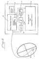
- figure 2 shows a block diagram of an embodiment of a pacemaker according to the invention
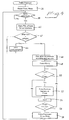
- figure 3 is a flow chart illustrating the overall collection of pulse pressure data in an embodiment of the apparatus according to the invention
- figure 4 is a flow chart explaining in greater detail an example of the procedure for obtaining pulse pressure data according to the present invention.
- pulse pressure is meant the varying pressure in aorta during a cardiac cycle.
- the above-mentioned pulse pressure can be obtained from the pressure measured in the left ventricle.
- the top curve shows the left ventricular pressure and the curve below the aortic pressure as a function of time.
- the magnitude of the pressures are indicated in arbitrary units in the figure.
- the asterisks in the curves of figure 1 denote time points for the maxima and minima of the time derivative of the left ventricular pressure, dLVP/dt max and dLVP/dt min respectively. As the aortic valves open close to the point dLVP/dt max , the aortic pressure is close to the left ventricular pressure at this point of time.
- the pulse pressure can consequently be obtained from left ventricular pressure by subtracting the pressure at the point of dLVP/dt max from the maximum of the left ventricular pressure obtained during the mentioned period.
- pressure signals from other parts of the hemodynamic system are morphologically similar to the left ventricular pressure
- these signals can also be used for determining the pulse pressure in the present invention, since only relative changes have to be determined for detecting DHF.
- FIG. 2 shows an embodiment of a pacemaker according to the invention comprising basic pacemaker circuits 20.
- a pressure sensor 2 is located in the right ventricle 18 of a patient's heart and connected to the pacemaker 4.
- the signals from the pressure sensor 2 are supplied to an A/D-converter 10. After A/D-conversion the time derivative of the signal is formed in a derivation unit 16.
- the time derivative of the pressure signals are filtered in the low pass filter 12 before supply to the microprocessor and supporting circuits 14. Since time derivation promotes high frequency noise, it is advisable to eliminate in this way possible false peaks and valleys, which could be interpreted as dLVP/dt max and dLVP/dt min .
- the filtered signals are supplied regularly into microprocessor and supporting circuits 14.
- an activity sensor 6 Located in the pacemaker 4 is an activity sensor 6 which is connected to an activity measuring unit 8 for determining the workload of the patient. A corresponding activity or workload signal is fed to the microprocessor and supporting circuits 14.
- Figure 3 is a flow chart illustrating an example of the overall process for collecting pulse pressure data.
- the development of DHF is a slow process as mentioned.
- a timer, at 26 in figure 3 is therefore provided for activating pulse pressure measurements on a regular basis for reducing the current drain and releasing microprocessor power.
- Collection of pulse pressure data is performed for different workloads of the patient, at 22 in figure 3 .
- the collection process is activated by a timer, at 26, and therefore the process has to wait for activation by the timer before starting, at 24.
- pulse pressure data are stored in different intermediate memory locations depending on the workload of the patient, at 30. Addresses to this memory locations are obtained from a table pointed to by the workload or activity measuring unit depending on the workload or activity, at 32. Pulse pressure data from the intermediate memory is then stored in another memory according to the address obtained in the preceding step for later analysis, at 34 .
- the procedure of storing pulse pressure data can be performed by forming a floating mean value.
- FIG. 4 is a flow chart illustrating in greater detail the procedure for obtaining the pulse pressure.
- P max and P min denote temporary storages of maximum and minimum aortic pressures.
- a QRS has to be detected , at 38 in figure 4 , after reset of P max and P min , at 36.
- Pressure samples P(i) are then stored continuously together with the time derivative dP(i)/dt for comparison, at 40.
- a certain number of contiguous samples have to exist simultaneously, so that the above-mentioned filtering of the time derivative of the pressure is in accordance with the length of the filter coefficients. Care must be taken so that the delay in the filter influences the selection of corresponding pressure samples in a timely fashion, i.e. the pressure samples are picked with the same delay.
- Photo-plethysmographic signals from a sensor placed close to the tissue at the location of the implanted pacemaker or ICD contains information on pulse pressure.
- photo-pletysmographic signals can be used as an alternative for determining the pulse pressure.
Landscapes
- Health & Medical Sciences (AREA)
- Life Sciences & Earth Sciences (AREA)
- Cardiology (AREA)
- Heart & Thoracic Surgery (AREA)
- Public Health (AREA)
- Veterinary Medicine (AREA)
- General Health & Medical Sciences (AREA)
- Animal Behavior & Ethology (AREA)
- Engineering & Computer Science (AREA)
- Biomedical Technology (AREA)
- Biophysics (AREA)
- Radiology & Medical Imaging (AREA)
- Nuclear Medicine, Radiotherapy & Molecular Imaging (AREA)
- Physiology (AREA)
- Surgery (AREA)
- Pathology (AREA)
- Physics & Mathematics (AREA)
- Vascular Medicine (AREA)
- Molecular Biology (AREA)
- Medical Informatics (AREA)
- Hospice & Palliative Care (AREA)
- Electrotherapy Devices (AREA)
- Measuring Pulse, Heart Rate, Blood Pressure Or Blood Flow (AREA)
Description
- The present invention relates to an implantable medical apparatus for detecting diastolic heart failure, DHF, comprising a DHF determining device for determining at least one blood pressure parameter for detecting a DHF state of the heart of a patient. The invention also relates to a pacemaker provided with such an apparatus.
- There is a growing recognition that congestive heart failure caused by a predominant abnormality in the diastolic function, i.e. diastolic heart failure, DHF, is both common and causes significant morbidity and mortality. Therefore early detection of DHF is important. Patients do not, however, seem to have symptoms at an early stage. In addition it has been hard to separate diastolic and systolic heart failure and they may also exist simultaneously.
- It has been discovered that among the few parameters, separating diastolic heart failure from systolic heart failure, are certain blood pressure parameters obtained during work of the patient. Thus
US 6 438 408 describes an implantable medical device for monitoring congestive heart failure, CHF. A plurality of heart failure parameters indicative of the state of the heart failure are measured employing EGMs, blood pressures including absolute pressures, developed pressures (= systolic pressures - diastolic pressures) and the time derivative dP/dt, as well as heart chamber volumes. One of these parameters is the relaxation or contraction time constant τ of the heart chamber. τ is calculated from a continuous pressure signal and is the drop in ventricular pressure at the end of systole and in the first part of diastole. The τ parameter is thus a general parameter reflecting the relaxation process. - According to an article by Dalane W. Kitzman et al., Pathophysiological Characterization of Isolated Diastolic Heart Failure in Comparison to Systolic Heart Failure, JAMA vol. 288, No. 17, 2144, November 6, 2002 the exercise pulse pressure is one parameter separating systolic heart failure from diastolic heart failure.
- The purpose of the present invention is to utilize this knowledge to propose a technique for detecting DHF, preferably at an early stage when the patient still does not seem to have any symptoms, based on measurement of pulse pressure under work.
- This purpose is obtained by an apparatus and a pacemaker, of the kind mentioned in the introductory portion of the description and having the characterizing features of
claims 1 and 9 respectively. - Thus with the present invention the reduced peak and submaximal exercise performance of DHF patients is utilized for detecting DHF. With the technique according to the invention it is possible to detect DHF at an early stage, often before the patient seem to have any symptoms.
- In the present invention the workload situation of the patient must be identified, and therefore, according to an advantageous embodiment of the apparatus according to the invention, an activity sensor is provided for determining the workload of the patient.
- According to another advantageous embodiment of the apparatus according to the invention an averaging means is provided to form an average value of pulse pressures during a plurality of cardiac cycles with said workload situation and an average value of pulse pressures measured during a plurality of cardiac cycles with the patient in rest. In this way the quality of the pulse pressure measurements is improved.
- According to other advantageous embodiments of the apparatus according to the invention a wireless communication means is connected to said comparison means for automatically sending the results of the comparison of measured pulse pressures with said reference values to external receiver means, or a storing means is provided for storing the results of the comparison of measured pulse pressures with said reference values. Thus if the pulse pressure has risen above the reference value in a predetermined way this condition is automatically transmitted to a physician or stored for transmission in connection with a follow-up.
- According to still other advantageous embodiments of the apparatus according to the invention said pressure measuring means comprise a pressure sensor adapted for placement in right ventricle or coronary veins of the patient's heart, and said pressure measuring means are adapted to determine maximum and minimum pressures in a cardiac cycle. It is preferred to place the pressure sensor in the right ventricle or the coronary veins, since the pressures in these places reflect the morphology of the left ventricular or aortic pulse pressure, especially with regard to maximum and minimum pressures.
- The invention also relates to a pacemaker provided with the apparatus for detecting DHF and control means for optimising pacing therapy depending on the result of the comparison of said measured pulse pressures with said predetermined reference values. The pressure measuring means of the apparatus according to the invention then preferably comprises a pressure sensor connected to the pacemaker, since it can monitor the pulse pressure of its carrier for long periods. This is an advantage since evolvement of DHF is a slow process.
- An advantageous embodiment of the pacemaker according to the invention comprises a rate responsive sensor for use as activity sensor for determining the workload situation of the patient. Even the pressure sensor of the pacemaker can be used as activity sensor.
- According to an advantageous embodiment of the invention photo-plethysmographic signals are sensed for determining the pulse pressure, since it has been discovered that photo-plethysmographic signals obtained by a sensor placed close to the tissue where a pacemaker or ICD is implanted contain information about pulse pressure.
- As mentioned above the measured pulse pressure is compared with a predetermined reference value, and according to an advantageous embodiment of the apparatus according to the invention said pulse pressure in a cardiac cycle is measured for a predetermined workload situation and a rest situation of the patient, and the difference between said pulse pressures measured in said workload and rest situations is compared with a predetermined reference value for said difference for DHF detection. A condition of DHF is identified by a higher pulse pressure during workload than a patient with a systolic heart failure would have. The reference value for detection of DHF is preferably obtained from measurements on the patient at an early stage of the implantation period of the apparatus or pacemaker. The patient is supposed not to suffer from DHF at the time of implantation. Therefore, according to an advantageous embodiment of the invention, pulse pressures are measured for different workloads of the patient and for the patient in rest at an early time, when the patient is not suffering from DHF, for determining said reference values. These pulse pressures from an early stage can also be measured for a certain period of time and typical pulse pressures during an identified workload and during rest are gathered and averaged and then stored for later use as reference values for comparison purposes. If later the measured pulse pressure, or average pulse pressure measured during several cardiac cycles, exceeds the reference value determined in this way by a prescribed amount x%, this is used as an indication of DHF.
- To explain the invention in greater detail an embodiment of the invention will now be described with reference to the drawings on which
figure1 is a diagram showing the left ventricular and aortic pressures as a function of time,figure 2 shows a block diagram of an embodiment of a pacemaker according to the invention,figure 3 is a flow chart illustrating the overall collection of pulse pressure data in an embodiment of the apparatus according to the invention, andfigure 4 is a flow chart explaining in greater detail an example of the procedure for obtaining pulse pressure data according to the present invention. - In the following an embodiment of the invention using a pressure sensor will be described, and by the expression pulse pressure is meant the varying pressure in aorta during a cardiac cycle.
- The above-mentioned pulse pressure can be obtained from the pressure measured in the left ventricle. In
figure 1 the top curve shows the left ventricular pressure and the curve below the aortic pressure as a function of time. The magnitude of the pressures are indicated in arbitrary units in the figure. - The asterisks in the curves of
figure 1 denote time points for the maxima and minima of the time derivative of the left ventricular pressure, dLVP/dtmax and dLVP/dtmin respectively. As the aortic valves open close to the point dLVP/dtmax, the aortic pressure is close to the left ventricular pressure at this point of time. - During the period from dLVP/dtmax to dLVP/dtmin blood flows into aorta. The maximum of aortic pressure is situated in this period. The pulse pressure can consequently be obtained from left ventricular pressure by subtracting the pressure at the point of dLVP/dtmax from the maximum of the left ventricular pressure obtained during the mentioned period.
- If the conditions are such that pressure signals from other parts of the hemodynamic system are morphologically similar to the left ventricular pressure, these signals can also be used for determining the pulse pressure in the present invention, since only relative changes have to be determined for detecting DHF.
-
Figure 2 shows an embodiment of a pacemaker according to the invention comprisingbasic pacemaker circuits 20. Apressure sensor 2 is located in theright ventricle 18 of a patient's heart and connected to thepacemaker 4. The signals from thepressure sensor 2 are supplied to an A/D-converter 10. After A/D-conversion the time derivative of the signal is formed in aderivation unit 16. The time derivative of the pressure signals are filtered in thelow pass filter 12 before supply to the microprocessor and supportingcircuits 14. Since time derivation promotes high frequency noise, it is advisable to eliminate in this way possible false peaks and valleys, which could be interpreted as dLVP/dtmax and dLVP/dtmin. The filtered signals are supplied regularly into microprocessor and supportingcircuits 14. - Located in the
pacemaker 4 is anactivity sensor 6 which is connected to anactivity measuring unit 8 for determining the workload of the patient. A corresponding activity or workload signal is fed to the microprocessor and supportingcircuits 14. -
Figure 3 is a flow chart illustrating an example of the overall process for collecting pulse pressure data. The development of DHF is a slow process as mentioned. A timer, at 26 infigure 3 , is therefore provided for activating pulse pressure measurements on a regular basis for reducing the current drain and releasing microprocessor power. - Collection of pulse pressure data is performed for different workloads of the patient, at 22 in
figure 3 . As mentioned above the collection process is activated by a timer, at 26, and therefore the process has to wait for activation by the timer before starting, at 24. As the process is started, at 28, pulse pressure data are stored in different intermediate memory locations depending on the workload of the patient, at 30. Addresses to this memory locations are obtained from a table pointed to by the workload or activity measuring unit depending on the workload or activity, at 32. Pulse pressure data from the intermediate memory is then stored in another memory according to the address obtained in the preceding step for later analysis, at 34 . - To improve the accuracy of the data stored the procedure of storing pulse pressure data can be performed by forming a floating mean value. One way to do this is to add a
fraction 1/k of a new pulse pressure value P(i) to the pulse pressure value stored Pstored at the memory location pointed to by the activity measuring unit and form a mean value Pstore according to the following equation
-
Figure 4 is a flow chart illustrating in greater detail the procedure for obtaining the pulse pressure. Pmax and Pmin denote temporary storages of maximum and minimum aortic pressures. - In order to start the pulse pressure measurements a QRS has to be detected , at 38 in
figure 4 , after reset of Pmax and Pmin, at 36. Pressure samples P(i) are then stored continuously together with the time derivative dP(i)/dt for comparison, at 40. A certain number of contiguous samples have to exist simultaneously, so that the above-mentioned filtering of the time derivative of the pressure is in accordance with the length of the filter coefficients. Care must be taken so that the delay in the filter influences the selection of corresponding pressure samples in a timely fashion, i.e. the pressure samples are picked with the same delay. - When dP/dtmax has been found, at 42 and 44, the pressure at that point in time is selected as the minimum pressure Pmin. The pressure then rises in the aorta and the maximum pressure during systole occurs in the period between dP/dtmax and dP/dtmin, cf. the description of
figure 1 . In the process illustrated infigure 4 a simplified approach is used for determining maximum pressure Pmax. Instead of determing the point of time for dP/dtmin a timer is started at the point of dP/dtmax, at 46 infigure 4 and Pmax is determined according tosteps - Instead of determining the pulse pressure with the aid of pressure sensors it can be determined by photo-plethysmography. Photo-plethysmographic signals from a sensor placed close to the tissue at the location of the implanted pacemaker or ICD contains information on pulse pressure. Thus such photo-pletysmographic signals can be used as an alternative for determining the pulse pressure.
Claims (11)
- An implantable medical apparatus for detecting diastolic heart failure, DHF, comprising a DHF determining device for determining at least one blood pressure parameter for detecting a DHF state of the heart of a patient, said DHF determining device further comprising a pressure measuring means (2,10,12,16) adapted to measure the pulse pressure in a cardiac cycle for a predetermined workload situation and a rest situation of the patient, and a comparison means (14) adapted to compare the difference between said pulse pressures measured in said workload and rest situations with a predetermined reference value for said difference for DHF detection.
- The apparatus according to claims 1, characterized in that an activity sensor (6) is provided for determining the workload of the patient.
- The apparatus according to any of the preceding claims, characterized in that an averaging means (14) is provided to form an average value of pulse pressures during a plurality of cardiac cycles with said predetermined workload situation and an average value of pulse pressures measured during a plurality of cardiac cycles with the patient in rest.
- The apparatus according to any of the preceding claims, characterized in that a wireless communication means is connected to said comparison means (14) for automatically sending the results of the comparison of measured pulse pressures with said reference values to external receiver means.
- The apparatus according to any of the claims 1 - 3, characterized in that a storing means (14) is provided for storing the results of the comparison of measured pulse pressures with said reference values.
- The apparatus according to any of the preceding claims, characterized in that said pressure measuring means comprise a pressure sensor (2) adapted for placement in right ventricle (18) or coronary veins of the patient's heart.
- The apparatus according to any of the preceding claims, characterized in that said pressure measuring means (2,10,12,16) are adapted to determine maximum and minimum pressures in a cardiac cycle.
- The apparatus according to claims 1, characterized in that said pressure measuring means comprise a sensor for delivering photo-plethysmographic signals to be used for determing the pulse pressure.
- A pacemaker, characterized in that it comprises an apparatus according to any one of the preceding claims and control means (20) for optimising pacing therapy depending on the result of the comparison of said measured pulse pressures with said predetermined reference values.
- The pacemaker according to claim 9, characterized in that it comprises a rate responsive sensor (6) for determining the workload situation of the patient.
- The pacemaker according to claim 9 comprising a pressure sensor, characterized in that said pressure sensor (2) is arranged as said activity sensor.
Applications Claiming Priority (1)
| Application Number | Priority Date | Filing Date | Title |
|---|---|---|---|
| PCT/SE2004/000636 WO2005102451A1 (en) | 2004-04-26 | 2004-04-26 | Detection of diastolic heart failure |
Publications (2)
| Publication Number | Publication Date |
|---|---|
| EP1740266A1 EP1740266A1 (en) | 2007-01-10 |
| EP1740266B1 true EP1740266B1 (en) | 2009-03-18 |
Family
ID=35196753
Family Applications (1)
| Application Number | Title | Priority Date | Filing Date |
|---|---|---|---|
| EP04729568A Expired - Lifetime EP1740266B1 (en) | 2004-04-26 | 2004-04-26 | Detection of diastolic heart failure |
Country Status (4)
| Country | Link |
|---|---|
| US (1) | US7483742B2 (en) |
| EP (1) | EP1740266B1 (en) |
| DE (1) | DE602004020120D1 (en) |
| WO (1) | WO2005102451A1 (en) |
Families Citing this family (27)
| Publication number | Priority date | Publication date | Assignee | Title |
|---|---|---|---|---|
| US7775966B2 (en) | 2005-02-24 | 2010-08-17 | Ethicon Endo-Surgery, Inc. | Non-invasive pressure measurement in a fluid adjustable restrictive device |
| US7699770B2 (en) | 2005-02-24 | 2010-04-20 | Ethicon Endo-Surgery, Inc. | Device for non-invasive measurement of fluid pressure in an adjustable restriction device |
| US7927270B2 (en) | 2005-02-24 | 2011-04-19 | Ethicon Endo-Surgery, Inc. | External mechanical pressure sensor for gastric band pressure measurements |
| US7658196B2 (en) | 2005-02-24 | 2010-02-09 | Ethicon Endo-Surgery, Inc. | System and method for determining implanted device orientation |
| US8066629B2 (en) | 2005-02-24 | 2011-11-29 | Ethicon Endo-Surgery, Inc. | Apparatus for adjustment and sensing of gastric band pressure |
| US8016744B2 (en) | 2005-02-24 | 2011-09-13 | Ethicon Endo-Surgery, Inc. | External pressure-based gastric band adjustment system and method |
| US7775215B2 (en) | 2005-02-24 | 2010-08-17 | Ethicon Endo-Surgery, Inc. | System and method for determining implanted device positioning and obtaining pressure data |
| US8152710B2 (en) | 2006-04-06 | 2012-04-10 | Ethicon Endo-Surgery, Inc. | Physiological parameter analysis for an implantable restriction device and a data logger |
| US8870742B2 (en) | 2006-04-06 | 2014-10-28 | Ethicon Endo-Surgery, Inc. | GUI for an implantable restriction device and a data logger |
| US8060203B2 (en) * | 2006-08-28 | 2011-11-15 | St. Jude Medical Ab | Method and apparatus for determining variation over time of a medical parameter of a human being |
| US7946995B1 (en) * | 2006-11-09 | 2011-05-24 | Pacesetter, Inc. | Analyzing circadian variations of a hemodynamic parameter to determine an adverse cardiac condition |
| US8187163B2 (en) | 2007-12-10 | 2012-05-29 | Ethicon Endo-Surgery, Inc. | Methods for implanting a gastric restriction device |
| US8100870B2 (en) | 2007-12-14 | 2012-01-24 | Ethicon Endo-Surgery, Inc. | Adjustable height gastric restriction devices and methods |
| US8142452B2 (en) | 2007-12-27 | 2012-03-27 | Ethicon Endo-Surgery, Inc. | Controlling pressure in adjustable restriction devices |
| US8377079B2 (en) | 2007-12-27 | 2013-02-19 | Ethicon Endo-Surgery, Inc. | Constant force mechanisms for regulating restriction devices |
| US8192350B2 (en) | 2008-01-28 | 2012-06-05 | Ethicon Endo-Surgery, Inc. | Methods and devices for measuring impedance in a gastric restriction system |
| US8591395B2 (en) | 2008-01-28 | 2013-11-26 | Ethicon Endo-Surgery, Inc. | Gastric restriction device data handling devices and methods |
| US8337389B2 (en) | 2008-01-28 | 2012-12-25 | Ethicon Endo-Surgery, Inc. | Methods and devices for diagnosing performance of a gastric restriction system |
| US7844342B2 (en) | 2008-02-07 | 2010-11-30 | Ethicon Endo-Surgery, Inc. | Powering implantable restriction systems using light |
| US8221439B2 (en) | 2008-02-07 | 2012-07-17 | Ethicon Endo-Surgery, Inc. | Powering implantable restriction systems using kinetic motion |
| US8114345B2 (en) | 2008-02-08 | 2012-02-14 | Ethicon Endo-Surgery, Inc. | System and method of sterilizing an implantable medical device |
| US8057492B2 (en) | 2008-02-12 | 2011-11-15 | Ethicon Endo-Surgery, Inc. | Automatically adjusting band system with MEMS pump |
| US8591532B2 (en) | 2008-02-12 | 2013-11-26 | Ethicon Endo-Sugery, Inc. | Automatically adjusting band system |
| US8034065B2 (en) | 2008-02-26 | 2011-10-11 | Ethicon Endo-Surgery, Inc. | Controlling pressure in adjustable restriction devices |
| US8233995B2 (en) | 2008-03-06 | 2012-07-31 | Ethicon Endo-Surgery, Inc. | System and method of aligning an implantable antenna |
| US8187162B2 (en) | 2008-03-06 | 2012-05-29 | Ethicon Endo-Surgery, Inc. | Reorientation port |
| US20100234906A1 (en) * | 2009-03-16 | 2010-09-16 | Pacesetter, Inc. | System and method for controlling rate-adaptive pacing based on a cardiac force-frequency relation detected by an implantable medical device |
Family Cites Families (6)
| Publication number | Priority date | Publication date | Assignee | Title |
|---|---|---|---|---|
| SE9202937D0 (en) * | 1992-10-07 | 1992-10-07 | Siemens Elema Ab | FREQUENCY ADAPTIVE HEART STIMULATOR |
| US5476483A (en) * | 1994-06-10 | 1995-12-19 | Pacesetter, Inc. | System and method for modulating the base rate during sleep for a rate-responsive cardiac pacemaker |
| US6438408B1 (en) * | 2000-12-28 | 2002-08-20 | Medtronic, Inc. | Implantable medical device for monitoring congestive heart failure |
| DE10219367A1 (en) * | 2002-04-30 | 2003-11-13 | Jan Manolas | Device for determining and evaluating parameters of the diastolic function of the left ventricle |
| US6876881B2 (en) * | 2002-08-16 | 2005-04-05 | Cardiac Pacemakers, Inc. | Cardiac rhythm management system with respiration synchronous optimization of cardiac performance using atrial cycle length |
| US7363077B1 (en) * | 2004-11-09 | 2008-04-22 | Pacesetters, Inc. | Adaptive timing interval control method for treating congestive heart failure |
-
2004
- 2004-04-26 DE DE602004020120T patent/DE602004020120D1/en not_active Expired - Lifetime
- 2004-04-26 WO PCT/SE2004/000636 patent/WO2005102451A1/en not_active Ceased
- 2004-04-26 EP EP04729568A patent/EP1740266B1/en not_active Expired - Lifetime
- 2004-04-26 US US10/562,109 patent/US7483742B2/en not_active Expired - Fee Related
Also Published As
| Publication number | Publication date |
|---|---|
| EP1740266A1 (en) | 2007-01-10 |
| WO2005102451A1 (en) | 2005-11-03 |
| US7483742B2 (en) | 2009-01-27 |
| US20060149327A1 (en) | 2006-07-06 |
| DE602004020120D1 (en) | 2009-04-30 |
Similar Documents
| Publication | Publication Date | Title |
|---|---|---|
| US7483742B2 (en) | Detection of diastolic heart failure | |
| EP2328466B1 (en) | Central venous pressure sensor to control a fluid or volume overload therapy | |
| US6915162B2 (en) | Implantable medical device for measuring ventricular pressure | |
| EP1341439B1 (en) | Apparatus for measurement of mean pulmonary artery pressure from a ventricle in an ambulatory monitor | |
| EP1848330B1 (en) | Method and apparatus for continuous pulse contour cardiac output | |
| US7367951B2 (en) | System and method for detecting cardiovascular health conditions using hemodynamic pressure waveforms | |
| EP1971395B1 (en) | System for interpreting hemodynamic data incorporating patient posture information | |
| US8632470B2 (en) | Assessment of pulmonary vascular resistance via pulmonary artery pressure | |
| EP0536782A1 (en) | A method and apparatus for excluding artifacts from automatic blood pressure measurements | |
| EP2346401A1 (en) | Heart failure detector | |
| EP2280760B1 (en) | A system to monitor ejection time and qt interval to alert patients before syncopal events | |
| EP1697000B1 (en) | Detection of diastolic heart failure | |
| EP1538979B1 (en) | A congestive heart failure monitor | |
| EP3749382B1 (en) | Determining control parameters for cardiac augmentation devices | |
| EP2164564B1 (en) | A device for collecting rem sleep data | |
| WO2006081590A2 (en) | System and method for monitoring myocardial performance using sensed ventricular pressures | |
| EP2225000B1 (en) | An implantable heart monitoring device with means for measuring atrial volume change | |
| WO2009002237A1 (en) | A method and device for detecting rem sleep | |
| JPS62275436A (en) | Electronic hemomanometer |
Legal Events
| Date | Code | Title | Description |
|---|---|---|---|
| PUAI | Public reference made under article 153(3) epc to a published international application that has entered the european phase |
Free format text: ORIGINAL CODE: 0009012 |
|
| 17P | Request for examination filed |
Effective date: 20060427 |
|
| AK | Designated contracting states |
Kind code of ref document: A1 Designated state(s): CH DE FR IE IT LI |
|
| DAX | Request for extension of the european patent (deleted) | ||
| RBV | Designated contracting states (corrected) |
Designated state(s): CH DE FR IE IT LI |
|
| 17Q | First examination report despatched |
Effective date: 20070720 |
|
| GRAP | Despatch of communication of intention to grant a patent |
Free format text: ORIGINAL CODE: EPIDOSNIGR1 |
|
| GRAS | Grant fee paid |
Free format text: ORIGINAL CODE: EPIDOSNIGR3 |
|
| GRAA | (expected) grant |
Free format text: ORIGINAL CODE: 0009210 |
|
| AK | Designated contracting states |
Kind code of ref document: B1 Designated state(s): CH DE FR IE IT LI |
|
| REG | Reference to a national code |
Ref country code: CH Ref legal event code: EP Ref country code: CH Ref legal event code: NV Representative=s name: E. BLUM & CO. AG PATENT- UND MARKENANWAELTE VSP |
|
| REG | Reference to a national code |
Ref country code: IE Ref legal event code: FG4D |
|
| REF | Corresponds to: |
Ref document number: 602004020120 Country of ref document: DE Date of ref document: 20090430 Kind code of ref document: P |
|
| PLBE | No opposition filed within time limit |
Free format text: ORIGINAL CODE: 0009261 |
|
| STAA | Information on the status of an ep patent application or granted ep patent |
Free format text: STATUS: NO OPPOSITION FILED WITHIN TIME LIMIT |
|
| REG | Reference to a national code |
Ref country code: IE Ref legal event code: MM4A |
|
| 26N | No opposition filed |
Effective date: 20091221 |
|
| PG25 | Lapsed in a contracting state [announced via postgrant information from national office to epo] |
Ref country code: IE Free format text: LAPSE BECAUSE OF NON-PAYMENT OF DUE FEES Effective date: 20090426 |
|
| REG | Reference to a national code |
Ref country code: FR Ref legal event code: PLFP Year of fee payment: 12 |
|
| PGFP | Annual fee paid to national office [announced via postgrant information from national office to epo] |
Ref country code: FR Payment date: 20150417 Year of fee payment: 12 Ref country code: IT Payment date: 20150427 Year of fee payment: 12 |
|
| REG | Reference to a national code |
Ref country code: FR Ref legal event code: ST Effective date: 20161230 |
|
| PG25 | Lapsed in a contracting state [announced via postgrant information from national office to epo] |
Ref country code: FR Free format text: LAPSE BECAUSE OF NON-PAYMENT OF DUE FEES Effective date: 20160502 |
|
| PG25 | Lapsed in a contracting state [announced via postgrant information from national office to epo] |
Ref country code: IT Free format text: LAPSE BECAUSE OF NON-PAYMENT OF DUE FEES Effective date: 20160426 |
|
| PGFP | Annual fee paid to national office [announced via postgrant information from national office to epo] |
Ref country code: CH Payment date: 20190425 Year of fee payment: 16 |
|
| PGFP | Annual fee paid to national office [announced via postgrant information from national office to epo] |
Ref country code: DE Payment date: 20200317 Year of fee payment: 17 |
|
| REG | Reference to a national code |
Ref country code: CH Ref legal event code: PL |
|
| PG25 | Lapsed in a contracting state [announced via postgrant information from national office to epo] |
Ref country code: CH Free format text: LAPSE BECAUSE OF NON-PAYMENT OF DUE FEES Effective date: 20200430 Ref country code: LI Free format text: LAPSE BECAUSE OF NON-PAYMENT OF DUE FEES Effective date: 20200430 |
|
| REG | Reference to a national code |
Ref country code: DE Ref legal event code: R119 Ref document number: 602004020120 Country of ref document: DE |
|
| PG25 | Lapsed in a contracting state [announced via postgrant information from national office to epo] |
Ref country code: DE Free format text: LAPSE BECAUSE OF NON-PAYMENT OF DUE FEES Effective date: 20211103 |