EP1740030A2 - AC adapter - Google Patents
AC adapter Download PDFInfo
- Publication number
- EP1740030A2 EP1740030A2 EP06252202A EP06252202A EP1740030A2 EP 1740030 A2 EP1740030 A2 EP 1740030A2 EP 06252202 A EP06252202 A EP 06252202A EP 06252202 A EP06252202 A EP 06252202A EP 1740030 A2 EP1740030 A2 EP 1740030A2
- Authority
- EP
- European Patent Office
- Prior art keywords
- name plate
- adapter
- metallic sheet
- concave portion
- case
- Prior art date
- Legal status (The legal status is an assumption and is not a legal conclusion. Google has not performed a legal analysis and makes no representation as to the accuracy of the status listed.)
- Granted
Links
Images



Classifications
-
- H—ELECTRICITY
- H05—ELECTRIC TECHNIQUES NOT OTHERWISE PROVIDED FOR
- H05K—PRINTED CIRCUITS; CASINGS OR CONSTRUCTIONAL DETAILS OF ELECTRIC APPARATUS; MANUFACTURE OF ASSEMBLAGES OF ELECTRICAL COMPONENTS
- H05K9/00—Screening of apparatus or components against electric or magnetic fields
- H05K9/0007—Casings
- H05K9/0045—Casings being rigid plastic containers having a coating of shielding material
-
- H—ELECTRICITY
- H05—ELECTRIC TECHNIQUES NOT OTHERWISE PROVIDED FOR
- H05K—PRINTED CIRCUITS; CASINGS OR CONSTRUCTIONAL DETAILS OF ELECTRIC APPARATUS; MANUFACTURE OF ASSEMBLAGES OF ELECTRICAL COMPONENTS
- H05K5/00—Casings, cabinets or drawers for electric apparatus
- H05K5/02—Details
- H05K5/0252—Labels, e.g. for identification, markings or configuration store
-
- H—ELECTRICITY
- H05—ELECTRIC TECHNIQUES NOT OTHERWISE PROVIDED FOR
- H05K—PRINTED CIRCUITS; CASINGS OR CONSTRUCTIONAL DETAILS OF ELECTRIC APPARATUS; MANUFACTURE OF ASSEMBLAGES OF ELECTRICAL COMPONENTS
- H05K7/00—Constructional details common to different types of electric apparatus
- H05K7/20—Modifications to facilitate cooling, ventilating, or heating
- H05K7/2039—Modifications to facilitate cooling, ventilating, or heating characterised by the heat transfer by conduction from the heat generating element to a dissipating body
- H05K7/20409—Outer radiating structures on heat dissipating housings, e.g. fins integrated with the housing
- H05K7/20418—Outer radiating structures on heat dissipating housings, e.g. fins integrated with the housing the radiating structures being additional and fastened onto the housing
-
- H—ELECTRICITY
- H05—ELECTRIC TECHNIQUES NOT OTHERWISE PROVIDED FOR
- H05K—PRINTED CIRCUITS; CASINGS OR CONSTRUCTIONAL DETAILS OF ELECTRIC APPARATUS; MANUFACTURE OF ASSEMBLAGES OF ELECTRICAL COMPONENTS
- H05K9/00—Screening of apparatus or components against electric or magnetic fields
- H05K9/0007—Casings
- H05K9/0058—Casings specially adapted for optoelectronic applications
Definitions
- the present invention relates to an AC adapter for a portable device.
- FIG. 1 is a perspective view showing a conventional AC adapter 1 with an AC cord.
- the AC adapter 1 includes a switching regulator circuit embedded in a synthetic resin case 4 prepared by combining a lower half case 2 with an upper half case 3.
- An AC cord 11 having an AC plug 10 at a tip thereof extends from one side of the case 4 and a DC cord 21 having a plug 20 at a tip thereof extends from the other side of the case 4.
- a name plate 22 is attached to a surface of the case 4.
- the name plate 22 includes a synthetic resin sheet in a front surface thereof and an aluminum sheet portion 23 for diffuse radiation in the whole area of a back surface thereof.
- the name plate 22 has substantially the same size as that of the surface of the case 4.
- the aluminum sheet portion 23 covers substantially the whole area of the surface of the case 4.
- the AC adapter 1 is used by inserting the AC plug 10 into an outlet and connecting the plug 20 to a portable device.
- a noise is generated in each on/off operation repeatedly performed by a switching regulator circuit. Such a noise may be partially transmitted to the AC plug 10 via the AC cord 11.
- the noise transmitted via the AC cord 11 is referred to as "noise terminal voltage”.
- This noise terminal voltage is transmitted to other electronic devices via the outlet and home wiring and affects the electronic devices connected to other outlets. Thus, it is preferable to reduce the noise terminal voltage in the AC adapter 1 as much as possible.
- the aluminum sheet portion 23 covers substantially the whole area of the surface of the case 4 and a portion of the aluminum sheet portion 23 reaches a portion for an AC input terminal to which the AC cord 11 is connected.
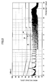
- line I indicates the result of measurement of noise terminal voltage in the conventional AC adapter 1 using a spectrum analyzer and a receiver.
- the horizontal axis indicates frequency and the vertical axis indicates noise levels.
- Vin is 120V/60Hz and Io is 2A.
- line II indicates an average noise terminal voltage (AV) determined by the standards and line III indicates a quasi peak value (QP) of a peak noise terminal voltage.
- AV average noise terminal voltage
- QP quasi peak value
- a margin thereof such as a margin M relative to the peak noise terminal voltage is relatively small.
- the AC adapter it is required to enlarge the aforementioned margin by further reducing the noise terminal voltage in order to improve the quality of the AC adapter.
- a more specific object of the present invention is to provide an AC adapter by which the quality thereof is improved in terms of the noise terminal voltage.
- the present invention provides an AC adapter including a synthetic resin case, and a switching regulator circuit assembly having an AC input terminal and a DC output terminal, the switching regulator circuit assembly being housed in the synthetic resin case, the AC adapter being characterized in that a metallic sheet for heat radiation is separated from a resin name plate and the metallic sheet is attached to a surface of the case except for a portion for the AC input terminal.
- the metallic sheet does not exist in the portion for the AC input terminal, so that the noise terminal voltage is not propagated to the AC input terminal via the metallic sheet.
- the quality of the AC adapter is improved in terms of the noise terminal voltage.
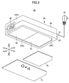
- FIG. 3 is a perspective view showing an AC adapter 30 with an inlet plug for a portable device according to the embodiment of the present invention when viewed from below, including an exploded view of an aluminum sheet and a name plate.
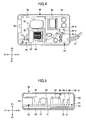
- FIG. 4 is a plan view showing the inside of the AC adapter 30 without an upper half case.
- FIG. 5 is a cross-sectional view of the AC adapter 30.
- X1-X2 indicates a width direction
- Y1-Y2 indicates a longitudinal direction
- Z1-Z2 indicates a height direction.
- the AC adapter 30 includes a switching regulator circuit assembly 40 embedded in a synthetic resin case 34 prepared by combining a lower half case 32 with an upper half case 33.
- An inlet plug 45 is exposed on a surface 34Y2 positioned on a Y2 side of the case 34
- a DC cord 61 having a plug 60 at a tip thereof extends from a surface 34Y1 positioned on a Y1 side of the case 34
- an aluminum sheet 70 and a synthetic resin name plate 71 are attached to a surface 34Z2 positioned on a Z2 side of the case 34.
- a transformer 42 and the like are mounted on a top surface of a printed board 41, an AC input terminal 43 is disposed on the Y2 side of the printed board 41, and a DC output terminal 44 is disposed on the Y1 side of the printed board 41.
- the inlet plug 45 is connected to the AC input terminal 43 and the DC cord 61 is connected to the DC output terminal 44.
- a line filter 46 and a film capacitor 47 are mounted between the AC input terminal 43 and the transformer 42. The line filter 46 and the film capacitor 47 are configured to prevent a noise mainly generated in the transformer 42 from propagating to the AC input terminal 43, the noise being generated in each on/off operation repeatedly performed by the switching regulator circuit.
- SBD Schottky diodes
- the Schottky diodes 48-1, 48-2, and 48-3 generate heat in particular and become main heat sources.
- the printed board 41 is fixed at the bottom of the lower half case 32.
- a shallow concave portion 50 for the name plate 71 having a size in accordance with the size of the name plate 71 is formed on the whole area of the surface 34Z2 positioned on the Z2 side of the case 34 and a deep concave portion 51 for the aluminum sheet 70 having a size in accordance with the size of the aluminum sheet 70 is formed on a portion of the Y1 side having about a half of the whole area.
- the concave portion 51 has steps relative to the surface 34Z2 and the concave portion 50.
- the aluminum sheet 70 is a separate member having a thickness of 50 ⁇ m and a size of substantially the half of the surface 34Z2 of the case 34.
- the aluminum sheet 70 is positioned and attached in accordance with the concave portion 51. As shown in FIG. 5, the aluminum sheet 70 is placed within the concave portion 51. Also, as shown in FIG. 4, the aluminum sheet 70 covers an area for the Schottky diodes 48-1, 48-2, and 48-3.
- the name plate 71 has a thickness of 50 ⁇ m and positioned and attached in accordance with the concave portion 50. As shown in FIG. 5, the name plate 71 is placed within the concave portion 50 and covers the aluminum sheet 70. A surface of the attached name plate 71 is flat and equal to the surface 34Z2.
- the aluminum sheet 70 is not extended to a portion for the line filter 46, the film capacitor 47, and the AC input terminal 43.
- the aluminum sheet 70 does not exist beneath the line filter 46 to the AC input terminal 43.
- the noise generated in each on/off operation repeatedly performed by the switching regulator circuit is propagated in the aluminum sheet 70, the propagation is restricted to a portion positioned substantially on the Y1 side relative to the AC input terminal 43.
- the noise propagated in the aluminum sheet 70 is prevented from reaching the inlet plug 45 via the AC input terminal 43. In other words, the "noise terminal voltage" resulting from the aluminum sheet 70 is not generated.
- the name plate 71 is integrated with the aluminum sheet 70, it is difficult to manufacture the name plate 71 since the size of the aluminum sheet 70 is different from that of the name plate 71.
- the aluminum sheet 70 is a separate member, so that it is easy to manufacture the name plate 71. (Characteristics and the like of noise terminal voltage in the AC adapter 30)
- line IA indicates noise terminal voltage in the aforementioned AC adapter 30 measured using the same test conditions mentioned above.
- a margin MA is enlarged and MA > M in comparison with FIG. 2.
- line X indicates the result of measuring the temperature of a portion of the aluminum 70 for lower portions of the Schottky diodes 48-1, 48-2, and 48-3 when the AC adapter 30 is used in an environment where ambient temperature Ta is about 28 degrees, Vin is 120V/50Hz, and Io is 2A.
- Line XI indicates the result of measuring the temperature of a portion of the bottom of the lower half case 32 for lower portions of the Schottky diodes 48-1, 48-2, and 48-3 when the test is conducted without attaching the aluminum sheet 70.
- the increase of the temperature is limited to 60 °C and the difference of temperature ⁇ T from the ambient temperature Ta is controlled to 31.8 °C, thereby reducing the difference of temperature ⁇ T by about 10 °C in comparison with the case where the aluminum sheet 70 is not attached.
- the size of the aluminum sheet 70 is substantially a half of that of the surface 34Z2 of the case 34, the aluminum sheet 70 is capable of radiating heat in a diffuse manner.
- the size and arrangement of the aluminum sheet 70 are not limited to the aforementioned size and arrangement.
- the aluminum sheet 70 has certain effects when an end thereof is distanced from the AC input terminal 43.
- the structure of the aluminum sheet 70 attached as mentioned above can be applied to an AC adapter with an AC cord and the same effects are obtained.
Landscapes
- Engineering & Computer Science (AREA)
- Microelectronics & Electronic Packaging (AREA)
- Physics & Mathematics (AREA)
- Thermal Sciences (AREA)
- Rectifiers (AREA)
- Dc-Dc Converters (AREA)
Abstract
Description
- The present invention relates to an AC adapter for a portable device.
- FIG. 1 is a perspective view showing a
conventional AC adapter 1 with an AC cord. TheAC adapter 1 includes a switching regulator circuit embedded in asynthetic resin case 4 prepared by combining alower half case 2 with anupper half case 3. AnAC cord 11 having anAC plug 10 at a tip thereof extends from one side of thecase 4 and aDC cord 21 having aplug 20 at a tip thereof extends from the other side of thecase 4. And aname plate 22 is attached to a surface of thecase 4. - The
name plate 22 includes a synthetic resin sheet in a front surface thereof and an aluminum sheet portion 23 for diffuse radiation in the whole area of a back surface thereof. Thename plate 22 has substantially the same size as that of the surface of thecase 4. The aluminum sheet portion 23 covers substantially the whole area of the surface of thecase 4. - The
AC adapter 1 is used by inserting theAC plug 10 into an outlet and connecting theplug 20 to a portable device. A noise is generated in each on/off operation repeatedly performed by a switching regulator circuit. Such a noise may be partially transmitted to theAC plug 10 via theAC cord 11. The noise transmitted via theAC cord 11 is referred to as "noise terminal voltage". This noise terminal voltage is transmitted to other electronic devices via the outlet and home wiring and affects the electronic devices connected to other outlets. Thus, it is preferable to reduce the noise terminal voltage in theAC adapter 1 as much as possible. - In the
conventional AC adapter 1, the aluminum sheet portion 23 covers substantially the whole area of the surface of thecase 4 and a portion of the aluminum sheet portion 23 reaches a portion for an AC input terminal to which theAC cord 11 is connected. - In FIG. 2, line I indicates the result of measurement of noise terminal voltage in the
conventional AC adapter 1 using a spectrum analyzer and a receiver. The horizontal axis indicates frequency and the vertical axis indicates noise levels. As the test conditions, Vin is 120V/60Hz and Io is 2A. In FIG. 2, line II indicates an average noise terminal voltage (AV) determined by the standards and line III indicates a quasi peak value (QP) of a peak noise terminal voltage. - As shown in FIG. 2, although the noise terminal voltage meets the standards, a margin thereof, such as a margin M relative to the peak noise terminal voltage is relatively small.
- Accordingly, in the AC adapter, it is required to enlarge the aforementioned margin by further reducing the noise terminal voltage in order to improve the quality of the AC adapter.
- In light of such requirement, the present invention has been made.
- It is a general object of the present invention to provide an improved and useful AC adapter in which the above-mentioned problem is eliminated.
- A more specific object of the present invention is to provide an AC adapter by which the quality thereof is improved in terms of the noise terminal voltage.
- The present invention provides an AC adapter including a synthetic resin case, and a switching regulator circuit assembly having an AC input terminal and a DC output terminal, the switching regulator circuit assembly being housed in the synthetic resin case, the AC adapter being characterized in that a metallic sheet for heat radiation is separated from a resin name plate and the metallic sheet is attached to a surface of the case except for a portion for the AC input terminal.
- According to the present invention, the metallic sheet does not exist in the portion for the AC input terminal, so that the noise terminal voltage is not propagated to the AC input terminal via the metallic sheet. Thus, the quality of the AC adapter is improved in terms of the noise terminal voltage.
-
- FIG. 1 is a perspective view showing a conventional AC adapter having a name plate on a top surface thereof;
- FIG. 2 is a chart showing the generation of noise terminal voltage in the conventional AC adapter in FIG. 1;
- FIG. 3 is a perspective view showing an AC adapter according to an embodiment of the present invention when viewed from below, including an exploded view of an aluminum sheet and a name plate;
- FIG. 4 is a plan view showing the AC adapter in FIG. 3 without an upper half case;
- FIG. 5 is a cross-sectional view of the AC adapter in FIG. 3;
- FIG. 6 is a chart showing the generation of noise terminal voltage in the AC adapter in FIG. 3; and
- FIG. 7 is a chart showing the characteristics of heat radiation in the AC adapter in FIG. 3.
- In the following, an embodiment of the present invention will be described with reference to the accompanying drawings.
- FIG. 3 is a perspective view showing an
AC adapter 30 with an inlet plug for a portable device according to the embodiment of the present invention when viewed from below, including an exploded view of an aluminum sheet and a name plate. FIG. 4 is a plan view showing the inside of theAC adapter 30 without an upper half case. And FIG. 5 is a cross-sectional view of theAC adapter 30. X1-X2 indicates a width direction, Y1-Y2 indicates a longitudinal direction, and Z1-Z2 indicates a height direction. - As shown in FIGS. 3 to 5, the
AC adapter 30 includes a switchingregulator circuit assembly 40 embedded in asynthetic resin case 34 prepared by combining alower half case 32 with anupper half case 33. Aninlet plug 45 is exposed on a surface 34Y2 positioned on a Y2 side of thecase 34, aDC cord 61 having aplug 60 at a tip thereof extends from a surface 34Y1 positioned on a Y1 side of thecase 34, and analuminum sheet 70 and a syntheticresin name plate 71 are attached to a surface 34Z2 positioned on a Z2 side of thecase 34. - In the switching
regulator circuit assembly 40, as shown in FIGS. 4 and 5, atransformer 42 and the like are mounted on a top surface of a printedboard 41, anAC input terminal 43 is disposed on the Y2 side of the printedboard 41, and aDC output terminal 44 is disposed on the Y1 side of the printedboard 41. Theinlet plug 45 is connected to theAC input terminal 43 and theDC cord 61 is connected to theDC output terminal 44. Further, aline filter 46 and afilm capacitor 47 are mounted between theAC input terminal 43 and thetransformer 42. Theline filter 46 and thefilm capacitor 47 are configured to prevent a noise mainly generated in thetransformer 42 from propagating to theAC input terminal 43, the noise being generated in each on/off operation repeatedly performed by the switching regulator circuit. Also, three Schottky diodes (SBD) 48-1, 48-2, and 48-3 are mounted between thetransformer 42 and theDC output terminal 44. The Schottky diodes 48-1, 48-2, and 48-3 generate heat in particular and become main heat sources. The printedboard 41 is fixed at the bottom of thelower half case 32. - A shallow
concave portion 50 for thename plate 71 having a size in accordance with the size of thename plate 71 is formed on the whole area of the surface 34Z2 positioned on the Z2 side of thecase 34 and a deepconcave portion 51 for thealuminum sheet 70 having a size in accordance with the size of thealuminum sheet 70 is formed on a portion of the Y1 side having about a half of the whole area. Theconcave portion 51 has steps relative to the surface 34Z2 and theconcave portion 50. - The
aluminum sheet 70 is a separate member having a thickness of 50 µm and a size of substantially the half of the surface 34Z2 of thecase 34. Thealuminum sheet 70 is positioned and attached in accordance with theconcave portion 51. As shown in FIG. 5, thealuminum sheet 70 is placed within theconcave portion 51. Also, as shown in FIG. 4, thealuminum sheet 70 covers an area for the Schottky diodes 48-1, 48-2, and 48-3. - The
name plate 71 has a thickness of 50 µm and positioned and attached in accordance with theconcave portion 50. As shown in FIG. 5, thename plate 71 is placed within theconcave portion 50 and covers thealuminum sheet 70. A surface of the attachedname plate 71 is flat and equal to the surface 34Z2. - The
aluminum sheet 70 is not extended to a portion for theline filter 46, thefilm capacitor 47, and theAC input terminal 43. Thealuminum sheet 70 does not exist beneath theline filter 46 to theAC input terminal 43. Thus, although the noise generated in each on/off operation repeatedly performed by the switching regulator circuit is propagated in thealuminum sheet 70, the propagation is restricted to a portion positioned substantially on the Y1 side relative to theAC input terminal 43. The noise propagated in thealuminum sheet 70 is prevented from reaching theinlet plug 45 via theAC input terminal 43. In other words, the "noise terminal voltage" resulting from thealuminum sheet 70 is not generated. - In addition, if the
name plate 71 is integrated with thealuminum sheet 70, it is difficult to manufacture thename plate 71 since the size of thealuminum sheet 70 is different from that of thename plate 71. In the present embodiment, thealuminum sheet 70 is a separate member, so that it is easy to manufacture thename plate 71.
(Characteristics and the like of noise terminal voltage in the AC adapter 30) - In FIG. 6, line IA indicates noise terminal voltage in the
aforementioned AC adapter 30 measured using the same test conditions mentioned above. As shown in FIG. 6, a margin MA is enlarged and MA > M in comparison with FIG. 2. - In FIG. 7, line X indicates the result of measuring the temperature of a portion of the
aluminum 70 for lower portions of the Schottky diodes 48-1, 48-2, and 48-3 when theAC adapter 30 is used in an environment where ambient temperature Ta is about 28 degrees, Vin is 120V/50Hz, and Io is 2A. Line XI indicates the result of measuring the temperature of a portion of the bottom of thelower half case 32 for lower portions of the Schottky diodes 48-1, 48-2, and 48-3 when the test is conducted without attaching thealuminum sheet 70. - After 60 minutes has elapsed, when the
aluminum sheet 70 is not attached, the temperature reaches 69.4 °C and the difference of temperature ΔT from the ambient temperature Ta is 41.2 °C. By contrast, when thealuminum sheet 70 is attached, the increase of the temperature is limited to 60 °C and the difference of temperature ΔT from the ambient temperature Ta is controlled to 31.8 °C, thereby reducing the difference of temperature ΔT by about 10 °C in comparison with the case where thealuminum sheet 70 is not attached. In other words, although the size of thealuminum sheet 70 is substantially a half of that of the surface 34Z2 of thecase 34, thealuminum sheet 70 is capable of radiating heat in a diffuse manner. - The size and arrangement of the
aluminum sheet 70 are not limited to the aforementioned size and arrangement. Thealuminum sheet 70 has certain effects when an end thereof is distanced from theAC input terminal 43. - The structure of the
aluminum sheet 70 attached as mentioned above can be applied to an AC adapter with an AC cord and the same effects are obtained. - The present invention is not limited to the specifically disclosed embodiment, and variations and modifications may be made without departing from the scope of the present invention.
Claims (6)
- An AC adapter including a synthetic resin case, and a switching regulator circuit assembly having an AC input terminal and a DC output terminal, the switching regulator circuit assembly being housed in the synthetic resin case, the AC adapter being characterized in that
a metallic sheet for heat radiation is separated from a resin name plate and the metallic sheet is attached to a surface of the case except for a portion for the AC input terminal. - The AC adapter according to claim 1 wherein
the case includes, on the surface thereof, a first concave portion for the name plate having a form in accordance with the name plate, and
the name plate is attached in the first concave portion for the name plate, covering the attached metallic sheet. - The AC adapter according to claim 2 wherein
a depth of the first concave portion for the name plate is substantially equal to a thickness of the name plate. - The AC adapter according to claim 2 wherein
the case includes, on the surface thereof, a second concave portion for the metallic sheet having a form in accordance with the metallic sheet,
the second concave portion for the metallic sheet is formed in the first concave portion for the name plate deeper than the first concave portion for the name plate, and
the metallic sheet is attached in the second concave portion for the metallic sheet. - The AC adapter according to claim 4 wherein
a depth of the second concave portion for the metallic sheet is substantially equal to a thickness of the metallic sheet. - The AC adapter according to any one of claims 1, 2, and 4 wherein
the metallic sheet has a size smaller than that of the name plate and is attached on the DC output terminal side.
Applications Claiming Priority (1)
| Application Number | Priority Date | Filing Date | Title |
|---|---|---|---|
| JP2005192403A JP2007014137A (en) | 2005-06-30 | 2005-06-30 | AC adapter |
Publications (3)
| Publication Number | Publication Date |
|---|---|
| EP1740030A2 true EP1740030A2 (en) | 2007-01-03 |
| EP1740030A3 EP1740030A3 (en) | 2008-10-08 |
| EP1740030B1 EP1740030B1 (en) | 2009-12-09 |
Family
ID=37072949
Family Applications (1)
| Application Number | Title | Priority Date | Filing Date |
|---|---|---|---|
| EP06252202A Expired - Lifetime EP1740030B1 (en) | 2005-06-30 | 2006-04-24 | AC adapter |
Country Status (4)
| Country | Link |
|---|---|
| US (1) | US7300302B2 (en) |
| EP (1) | EP1740030B1 (en) |
| JP (1) | JP2007014137A (en) |
| DE (1) | DE602006010940D1 (en) |
Families Citing this family (23)
| Publication number | Priority date | Publication date | Assignee | Title |
|---|---|---|---|---|
| TWM301437U (en) * | 2006-04-25 | 2006-11-21 | Hipro Electronics Taiwan Co Lt | Power supply |
| JP2008061399A (en) * | 2006-08-31 | 2008-03-13 | Mitsumi Electric Co Ltd | AC adapter |
| US7515423B2 (en) * | 2006-09-22 | 2009-04-07 | Fu Zhun Precision Industry (Shen Zhen) Co., Ltd. | Heat dissipation device |
| TW200820885A (en) * | 2006-10-31 | 2008-05-01 | Delta Electronics Inc | Passive heat-dissipating type power supply capable of increasing heat-dissipating efficiency and manufacturing method thereof |
| US8441216B2 (en) | 2008-09-03 | 2013-05-14 | ALVA Systems, Inc. | Power supply system for a building |
| US8415590B2 (en) * | 2008-10-14 | 2013-04-09 | The Boeing Company | Temperature controlled electronics tray |
| USD705726S1 (en) * | 2010-04-01 | 2014-05-27 | Samsung Electronics Co., Ltd. | Adapter |
| USD654867S1 (en) * | 2010-08-23 | 2012-02-28 | Ilcon Gmbh | Power supply |
| US20120126621A1 (en) | 2010-11-10 | 2012-05-24 | Michael Scott Brownlee | Lighting system |
| CN102548341A (en) * | 2010-12-10 | 2012-07-04 | 旭丽电子(广州)有限公司 | Heat dissipation shell structure |
| TWM431338U (en) * | 2011-10-31 | 2012-06-11 | Ampower Technology Co Ltd | Socket and adapter |
| US20140110083A1 (en) * | 2012-10-22 | 2014-04-24 | Cheng Hong-Chang | Heat dissipating protective cover |
| US9196430B2 (en) * | 2012-11-16 | 2015-11-24 | Cooper Technologies Company | Electrical circuit protection device enclosure assembly and kit with device compatibility attachment |
| JP6048277B2 (en) * | 2013-03-28 | 2016-12-21 | 三菱電機株式会社 | AC adapter cover |
| USD750563S1 (en) * | 2013-11-04 | 2016-03-01 | Savant Systems, Llc | Lamp module for a lighting control system |
| USD712831S1 (en) * | 2013-12-23 | 2014-09-09 | Shenzhen Lepow Creative Technology Co., Ltd. | Portable power source |
| USD852741S1 (en) * | 2017-01-26 | 2019-07-02 | Videri Inc. | Power adapter |
| JP1664683S (en) * | 2019-12-11 | 2020-07-27 | ||
| USD1031653S1 (en) * | 2021-08-24 | 2024-06-18 | Kyungdong Navien Co., Ltd. | Power adapter for electric mat |
| USD1103100S1 (en) * | 2022-08-23 | 2025-11-25 | Shenzhen Jinqiu Network Technology Co., Ltd. | Power adapter |
| USD1044722S1 (en) * | 2023-02-16 | 2024-10-01 | Fsp Technology Inc. | Adapter |
| USD1044721S1 (en) * | 2023-02-16 | 2024-10-01 | Fsp Technology Inc. | Adapter |
| USD1121552S1 (en) * | 2024-11-18 | 2026-04-07 | Anker Innovations Technology Co., Ltd. | Generator input adapter |
Family Cites Families (9)
| Publication number | Priority date | Publication date | Assignee | Title |
|---|---|---|---|---|
| US4722022A (en) * | 1986-09-29 | 1988-01-26 | Amp Incorporated | Shielded line terminator enclosure |
| US5019767A (en) * | 1989-02-16 | 1991-05-28 | Nintendo Co., Ltd. | Portable power supply |
| US5726858A (en) * | 1996-05-23 | 1998-03-10 | Compaq Computer Corporation | Shielded electrical component heat sink apparatus |
| DE19708116C2 (en) * | 1997-02-28 | 1999-02-25 | Telefunken Microelectron | Arrangement for closing pressure equalization openings |
| DE19956675A1 (en) * | 1999-11-25 | 2001-05-31 | Daimler Chrysler Ag | Plastic housing for holding an assembly with electrical and electronic components on a circuit board |
| JP2004047157A (en) * | 2002-07-09 | 2004-02-12 | Izumi Products Co | Power supply feeder |
| TWM249355U (en) * | 2002-10-02 | 2004-11-01 | Delta Electronics Inc | Waterproof and heat dissipating structure for electronic device |
| TWI220585B (en) * | 2003-07-23 | 2004-08-21 | Delta Electronics Inc | An inlet with a heat-isolation element |
| TWI256192B (en) * | 2004-04-15 | 2006-06-01 | Acbel Polytech Inc | Power adapter with heat sink device |
-
2005
- 2005-06-30 JP JP2005192403A patent/JP2007014137A/en not_active Withdrawn
-
2006
- 2006-04-21 US US11/408,523 patent/US7300302B2/en not_active Expired - Fee Related
- 2006-04-24 EP EP06252202A patent/EP1740030B1/en not_active Expired - Lifetime
- 2006-04-24 DE DE602006010940T patent/DE602006010940D1/en not_active Expired - Fee Related
Also Published As
| Publication number | Publication date |
|---|---|
| JP2007014137A (en) | 2007-01-18 |
| US7300302B2 (en) | 2007-11-27 |
| US20070002597A1 (en) | 2007-01-04 |
| DE602006010940D1 (en) | 2010-01-21 |
| EP1740030A3 (en) | 2008-10-08 |
| EP1740030B1 (en) | 2009-12-09 |
Similar Documents
| Publication | Publication Date | Title |
|---|---|---|
| EP1740030B1 (en) | AC adapter | |
| US7549790B2 (en) | Measuring apparatus for thermal resistance of heat dissipating device | |
| US6643135B2 (en) | On board mounting electronic apparatus and on board mounting electric power supply | |
| US9317079B2 (en) | Media content device with customized panel | |
| US7848088B2 (en) | Mounting apparatus for power supply | |
| BRPI0802084A2 (en) | expanded block control unit | |
| US7952877B2 (en) | Electronic apparatus | |
| US20110294309A1 (en) | Expansion card and expansion apparatus thereof | |
| BRPI0505501A (en) | power module cartridge | |
| US20040218375A1 (en) | Thermal interface adapter plate conversion kit and method | |
| JP2005268019A (en) | Socket for mounting electronic components | |
| JP2014239105A (en) | Mounting structure between power supply circuit board and chassis | |
| JP2013207288A (en) | Electronic apparatus | |
| US7637467B2 (en) | Stand for supporting computer | |
| EP1555865A3 (en) | Assembly of a trap circuit with discrete, passive electronic components | |
| US20120169549A1 (en) | Antenna module and portable electronic device using the same | |
| US20090168361A1 (en) | Printed circuit board assembly | |
| JP4197292B2 (en) | Electronic equipment | |
| JP2009290049A (en) | Insulating sheet, power supply circuit, and electronic device | |
| JP4266838B2 (en) | Electronic keyboard instrument mounting structure | |
| US20060133744A1 (en) | Optical transciever with capacitive coupled signal ground with chassis ground | |
| KR20090022555A (en) | Printed Circuit Board Mounting Device for Electronic Products | |
| JP2009049629A (en) | Earth grounding structure of tuner | |
| WO2010109648A1 (en) | Antenna unit and electronic device | |
| CN214852366U (en) | Circuit board convenient to assemble and fix |
Legal Events
| Date | Code | Title | Description |
|---|---|---|---|
| PUAI | Public reference made under article 153(3) epc to a published international application that has entered the european phase |
Free format text: ORIGINAL CODE: 0009012 |
|
| AK | Designated contracting states |
Kind code of ref document: A2 Designated state(s): AT BE BG CH CY CZ DE DK EE ES FI FR GB GR HU IE IS IT LI LT LU LV MC NL PL PT RO SE SI SK TR |
|
| AX | Request for extension of the european patent |
Extension state: AL BA HR MK YU |
|
| PUAL | Search report despatched |
Free format text: ORIGINAL CODE: 0009013 |
|
| AK | Designated contracting states |
Kind code of ref document: A3 Designated state(s): AT BE BG CH CY CZ DE DK EE ES FI FR GB GR HU IE IS IT LI LT LU LV MC NL PL PT RO SE SI SK TR |
|
| AX | Request for extension of the european patent |
Extension state: AL BA HR MK YU |
|
| RIC1 | Information provided on ipc code assigned before grant |
Ipc: H05K 5/02 20060101AFI20080901BHEP Ipc: H05K 9/00 20060101ALI20080901BHEP |
|
| 17P | Request for examination filed |
Effective date: 20081217 |
|
| GRAP | Despatch of communication of intention to grant a patent |
Free format text: ORIGINAL CODE: EPIDOSNIGR1 |
|
| AKX | Designation fees paid |
Designated state(s): DE FR |
|
| GRAS | Grant fee paid |
Free format text: ORIGINAL CODE: EPIDOSNIGR3 |
|
| GRAA | (expected) grant |
Free format text: ORIGINAL CODE: 0009210 |
|
| AK | Designated contracting states |
Kind code of ref document: B1 Designated state(s): DE FR |
|
| REF | Corresponds to: |
Ref document number: 602006010940 Country of ref document: DE Date of ref document: 20100121 Kind code of ref document: P |
|
| PLBE | No opposition filed within time limit |
Free format text: ORIGINAL CODE: 0009261 |
|
| STAA | Information on the status of an ep patent application or granted ep patent |
Free format text: STATUS: NO OPPOSITION FILED WITHIN TIME LIMIT |
|
| 26N | No opposition filed |
Effective date: 20100910 |
|
| REG | Reference to a national code |
Ref country code: FR Ref legal event code: ST Effective date: 20101230 |
|
| PG25 | Lapsed in a contracting state [announced via postgrant information from national office to epo] |
Ref country code: FR Free format text: LAPSE BECAUSE OF NON-PAYMENT OF DUE FEES Effective date: 20100430 |
|
| PG25 | Lapsed in a contracting state [announced via postgrant information from national office to epo] |
Ref country code: DE Free format text: LAPSE BECAUSE OF NON-PAYMENT OF DUE FEES Effective date: 20101103 |