EP1739793A2 - Lamp socket - Google Patents
Lamp socket Download PDFInfo
- Publication number
- EP1739793A2 EP1739793A2 EP06008659A EP06008659A EP1739793A2 EP 1739793 A2 EP1739793 A2 EP 1739793A2 EP 06008659 A EP06008659 A EP 06008659A EP 06008659 A EP06008659 A EP 06008659A EP 1739793 A2 EP1739793 A2 EP 1739793A2
- Authority
- EP
- European Patent Office
- Prior art keywords
- bight
- contact
- socket
- electrical contact
- recesses
- Prior art date
- Legal status (The legal status is an assumption and is not a legal conclusion. Google has not performed a legal analysis and makes no representation as to the accuracy of the status listed.)
- Granted
Links
Images


Classifications
-
- H—ELECTRICITY
- H01—ELECTRIC ELEMENTS
- H01R—ELECTRICALLY-CONDUCTIVE CONNECTIONS; STRUCTURAL ASSOCIATIONS OF A PLURALITY OF MUTUALLY-INSULATED ELECTRICAL CONNECTING ELEMENTS; COUPLING DEVICES; CURRENT COLLECTORS
- H01R13/00—Details of coupling devices of the kinds covered by groups H01R12/70 or H01R24/00 - H01R33/00
- H01R13/02—Contact members
- H01R13/15—Pins, blades or sockets having separate spring member for producing or increasing contact pressure
- H01R13/18—Pins, blades or sockets having separate spring member for producing or increasing contact pressure with the spring member surrounding the socket
-
- H—ELECTRICITY
- H01—ELECTRIC ELEMENTS
- H01R—ELECTRICALLY-CONDUCTIVE CONNECTIONS; STRUCTURAL ASSOCIATIONS OF A PLURALITY OF MUTUALLY-INSULATED ELECTRICAL CONNECTING ELEMENTS; COUPLING DEVICES; CURRENT COLLECTORS
- H01R33/00—Coupling devices specially adapted for supporting apparatus and having one part acting as a holder providing support and electrical connection via a counterpart which is structurally associated with the apparatus, e.g. lamp holders; Separate parts thereof
- H01R33/05—Two-pole devices
- H01R33/06—Two-pole devices with two current-carrying pins, blades or analogous contacts, having their axes parallel to each other
-
- H—ELECTRICITY
- H01—ELECTRIC ELEMENTS
- H01R—ELECTRICALLY-CONDUCTIVE CONNECTIONS; STRUCTURAL ASSOCIATIONS OF A PLURALITY OF MUTUALLY-INSULATED ELECTRICAL CONNECTING ELEMENTS; COUPLING DEVICES; CURRENT COLLECTORS
- H01R13/00—Details of coupling devices of the kinds covered by groups H01R12/70 or H01R24/00 - H01R33/00
- H01R13/40—Securing contact members in or to a base or case; Insulating of contact members
- H01R13/405—Securing in non-demountable manner, e.g. moulding, riveting
- H01R13/41—Securing in non-demountable manner, e.g. moulding, riveting by frictional grip in grommet, panel or base
-
- H—ELECTRICITY
- H01—ELECTRIC ELEMENTS
- H01R—ELECTRICALLY-CONDUCTIVE CONNECTIONS; STRUCTURAL ASSOCIATIONS OF A PLURALITY OF MUTUALLY-INSULATED ELECTRICAL CONNECTING ELEMENTS; COUPLING DEVICES; CURRENT COLLECTORS
- H01R13/00—Details of coupling devices of the kinds covered by groups H01R12/70 or H01R24/00 - H01R33/00
- H01R13/46—Bases; Cases
- H01R13/502—Bases; Cases composed of different pieces
-
- H—ELECTRICITY
- H01—ELECTRIC ELEMENTS
- H01R—ELECTRICALLY-CONDUCTIVE CONNECTIONS; STRUCTURAL ASSOCIATIONS OF A PLURALITY OF MUTUALLY-INSULATED ELECTRICAL CONNECTING ELEMENTS; COUPLING DEVICES; CURRENT COLLECTORS
- H01R4/00—Electrically-conductive connections between two or more conductive members in direct contact, i.e. touching one another; Means for effecting or maintaining such contact; Electrically-conductive connections having two or more spaced connecting locations for conductors and using contact members penetrating insulation
- H01R4/02—Soldered or welded connections
- H01R4/023—Soldered or welded connections between cables or wires and terminals
Definitions
- This invention relates to lamp sockets and more particularly to lamp sockets for bi-pin lamps. Still more particularly, it relates to lamp sockets utilizing novel electrical contacts.
- an electrical contact comprising a substantially U-shaped body having an open end and a bight, the U-shaped body comprising a contact portion formed of a first material nested within a substantially contiguous spring portion formed of a second material.
- This two-piece contact design allows the contact to be compliant for an entire range of tolerances. Further, it allows the contact to have a material with a relatively high conductance for contacting the mating lamp pin. The terminal does not require plating, thus providing extremely long life.
- the socket comprises an electrically insulating primary housing including a receptacle, and a secondary housing formed to be received in the receptacle.
- the secondary housing has a body with a pair of recesses therein.
- the recesses have a floor including a pin-receiving aperture.
- a substantially U-shaped electrical contact is positioned in each recess with the open ends thereof facing the floor, each of the electrical contacts comprising a contact portion formed of a first material nested within a substantially contiguous spring portion formed of a second material.
- Fig. 1 is a diagrammatic elevational view of a bi-pin lamp and socket assembly
- Fig. 2 is a perspective view of the spring portion of an electrical contact according to an aspect of the invention.
- Fig. 3 is a vertical sectional view of an assembled electrical contact according to an aspect of the invention.
- Fig. 4 is a perspective view of a secondary housing with a single electrical contact positioned therein;
- Fig. 5 is a perspective view of the underside of a secondary housing with a cover in place
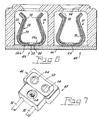
- Fig. 6 is an elevational sectional view of an assembled secondary housing
- Fig. 7 is a perspective view of an assembled secondary housing before assembly into a socket.
- the socket 40 for a bi-pin lamp 41.
- the socket 40 comprises a primary housing 42, formed, for example, from aluminum, and including a receptacle 44.
- a secondary housing 46 (see Figs. 4-7) of a suitable ceramic material such as L-3 Steatite is formed to be received in the receptacle 44, the secondary housing 46 having a body 48 with a pair of recesses 50 therein.
- a floor 52 is provided in the recesses 50 and a pin-receiving aperture 54 is provided in the floor of each of the recesses 50.
- An electrical contact 10 (see Fig. 3) is positioned in each recess 50.
- Each electrical contact 10 comprises a substantially U-shaped body 12 having an open end 14 and a bight 16.
- the U-shaped body 12 is a two-piece construction comprising a substantially U-shaped contact portion 18 formed of a first material, for example, nickel, nested within a substantially U-shaped contiguous spring portion 20 formed of a second material, such as heat-treated stainless steel.
- the contact portion 18 of the electrical contact 10 has a protrusion 22 formed in the bight 16a thereof, the protrusion 22 being fitted into a matching opening 24 in the bight 16b of the spring portion 20.
- the protrusion 22 can be formed during the formation of the contact portion 18 and be friction-fitted into the opening 24 or, preferably, it can be formed directly into the opening 24, as by a coining operation after the contact portion and the spring portion are nested together.
- the bights 16a and 16b of the contact portion 18 and the spring portion 20 include first and second oppositely directed tabs 26, 28 that, in the case of tabs 26, fit into slots 60 in recesses 50 to aid in locating and stabilizing the contact 10 and allow it to float in the recess and, in the case of tabs 28, provide support for the projecting wire-engaging member 30 that is formed on bight 16a of the contact portion 18 as an extension of a tab 28.
- the wire-engaging member 30 is formed to crimp the center conductor of a wire 31; however, the wire-engaging member 30 could also be formed as flat tab with the center conductor of a wire 31 welded to it.
- the secondary housing 46 includes a through-hole 62 to receive a rivet 64 or other fastening device for securing an electrically insulating cover 66 formed, for example, of mica, to the housing 46 to maintain the contacts 10 within the recesses 50.
- a gap 70 exists between the contact portion 18 and the spring portion 20 near the bight 16 to insure that spring portion 20 and contact portion 18 are touching at the pin engagement area 72.
- an enhanced bi-pin lamp socket whose dual cantilevered beam design provides two well defined points of contact for the mating pins. Further, the two-piece design allows the contact to be compliant through an entire range of tolerances while also allowing for the use of a contact material having a relatively high conductance mate with the pins. The contact does not require plating to achieve this effect thereby greatly extending the life of the contact.
Landscapes
- Connector Housings Or Holding Contact Members (AREA)
- Coupling Device And Connection With Printed Circuit (AREA)
Abstract
Description
- TECHNICAL FIELD
- This invention relates to lamp sockets and more particularly to lamp sockets for bi-pin lamps. Still more particularly, it relates to lamp sockets utilizing novel electrical contacts.
- BACKGROUND ART
- Previous lamp sockets for bi-pin lamps have employed tangential contacts, which forced the contact points to change dramatically as the mating lamp pin was inserted, producing and increasing insertion force as the pin was inserted into the socket. This condition made it difficult to determine if the bulb was completely seated in the socket. Additionally, prior contacts often had to be plated to achieve the high conductance levels needed to transmit high current levels to the lamp. The plating was subject to wear, thus limiting the life of the socket.
- DISCLOSURE OF INVENTION
- It is, therefore, an object of the invention to obviate the disadvantages of the prior art.
- It is another object of the invention to enhance the seating of bi-pin lamps into an appropriate socket.
- It is yet another object of the invention to lengthen socket life.
- These objects are accomplished, in one aspect of the invention, by the provision of an electrical contact comprising a substantially U-shaped body having an open end and a bight, the U-shaped body comprising a contact portion formed of a first material nested within a substantially contiguous spring portion formed of a second material. This two-piece contact design allows the contact to be compliant for an entire range of tolerances. Further, it allows the contact to have a material with a relatively high conductance for contacting the mating lamp pin. The terminal does not require plating, thus providing extremely long life.
- The objects are further accomplished by the provision of socket for a bi-pin lamp. The socket comprises an electrically insulating primary housing including a receptacle, and a secondary housing formed to be received in the receptacle. The secondary housing has a body with a pair of recesses therein. The recesses have a floor including a pin-receiving aperture. A substantially U-shaped electrical contact is positioned in each recess with the open ends thereof facing the floor, each of the electrical contacts comprising a contact portion formed of a first material nested within a substantially contiguous spring portion formed of a second material.
- BRIEF DESCRIPTION OF THE DRAWINGS
- Fig. 1 is a diagrammatic elevational view of a bi-pin lamp and socket assembly;
- Fig. 2 is a perspective view of the spring portion of an electrical contact according to an aspect of the invention;
- Fig. 3 is a vertical sectional view of an assembled electrical contact according to an aspect of the invention;
- Fig. 4 is a perspective view of a secondary housing with a single electrical contact positioned therein;
- Fig. 5 is a perspective view of the underside of a secondary housing with a cover in place;
- Fig. 6 is an elevational sectional view of an assembled secondary housing; and
- Fig. 7 is a perspective view of an assembled secondary housing before assembly into a socket.
- BEST MODE FOR CARRYING OUT THE INVENTION
- For a better understanding of the present invention, together with other and further objects, advantages and capabilities thereof, reference is made to the following disclosure and appended claims taken in conjunction with the above-described drawings.
- Referring now to the drawings with greater particularity, there is shown in Fig. 1 a
socket 40 for abi-pin lamp 41. Thesocket 40 comprises aprimary housing 42, formed, for example, from aluminum, and including areceptacle 44. A secondary housing 46 (see Figs. 4-7) of a suitable ceramic material such as L-3 Steatite is formed to be received in thereceptacle 44, thesecondary housing 46 having abody 48 with a pair ofrecesses 50 therein. Afloor 52 is provided in therecesses 50 and a pin-receivingaperture 54 is provided in the floor of each of therecesses 50. An electrical contact 10 (see Fig. 3) is positioned in eachrecess 50. Eachelectrical contact 10 comprises a substantiallyU-shaped body 12 having anopen end 14 and abight 16. The U-shapedbody 12 is a two-piece construction comprising a substantiallyU-shaped contact portion 18 formed of a first material, for example, nickel, nested within a substantially U-shapedcontiguous spring portion 20 formed of a second material, such as heat-treated stainless steel. - The
contact portion 18 of theelectrical contact 10 has aprotrusion 22 formed in thebight 16a thereof, theprotrusion 22 being fitted into amatching opening 24 in the bight 16b of thespring portion 20. Theprotrusion 22 can be formed during the formation of thecontact portion 18 and be friction-fitted into theopening 24 or, preferably, it can be formed directly into theopening 24, as by a coining operation after the contact portion and the spring portion are nested together. - The
bights 16a and 16b of thecontact portion 18 and thespring portion 20 include first and second oppositely directedtabs tabs 26, fit intoslots 60 inrecesses 50 to aid in locating and stabilizing thecontact 10 and allow it to float in the recess and, in the case oftabs 28, provide support for the projecting wire-engagingmember 30 that is formed onbight 16a of thecontact portion 18 as an extension of atab 28. These features are illustrated in Fig. 4. As shown, the wire-engagingmember 30 is formed to crimp the center conductor of awire 31; however, the wire-engaging member 30 could also be formed as flat tab with the center conductor of awire 31 welded to it. - The
secondary housing 46 includes a through-hole 62 to receive arivet 64 or other fastening device for securing an electrically insulatingcover 66 formed, for example, of mica, to thehousing 46 to maintain thecontacts 10 within therecesses 50. - A
gap 70 exists between thecontact portion 18 and thespring portion 20 near thebight 16 to insure thatspring portion 20 andcontact portion 18 are touching at thepin engagement area 72. - Thus there is provided an enhanced bi-pin lamp socket whose dual cantilevered beam design provides two well defined points of contact for the mating pins. Further, the two-piece design allows the contact to be compliant through an entire range of tolerances while also allowing for the use of a contact material having a relatively high conductance mate with the pins. The contact does not require plating to achieve this effect thereby greatly extending the life of the contact.
- While there have been shown and described what are present considered to be the preferred embodiments of the invention, it will be apparent to those skilled in the art that various changes and modifications can be made herein without departing from the scope of the invention as defined by the appended claims.
Claims (9)
- A socket for a bi-pin lamp comprising:a primary housing including a receptacle:a secondary housing formed to be received in said receptacle, said secondary housing having a body with a pair of recesses therein;a floor in said recesses;a pin-receiving aperture in the floor of each of said recesses; anda substantially U-shaped electrical contact positioned in each recess with the open ends thereof facing said floor, each of said electrical contacts comprising a contact portion formed of a first material nested within a substantially contiguous spring portion formed of a second material.
- The socket of Claim 1 wherein said contact portion has a protrusion formed in the bight thereof, said protrusion being fitted into a matching opening in said spring portion.
- The socket of Claim 2, wherein the bight of said spring portion of said electrical contact includes first and second oppositely directed tabs.
- The socket of Claim 3 wherein said recesses in said secondary housing include slots for receiving said tabs.
- The socket of Claim 4 wherein the bight of said contact portion includes a projecting wire-engaging member.
- An electrical contact comprising:a substantially U-shaped body having an open end and a bight, said U-shaped body comprising a contact portion formed of a first material nested within a substantially contiguous spring portion formed of a second material.
- The electrical contact of Claim 6 1 wherein said contact portion has a protrusion formed in the bight thereof, said protrusion being fitted into a matching opening in said spring portion.
- The electrical contact of Claim 7 wherein the bight of said spring portion of said electrical contact includes first and second oppositely directed tabs.
- The electrical contact of Claim 8 wherein the bight of said contact portion includes a projecting wire-engaging member.
Applications Claiming Priority (1)
| Application Number | Priority Date | Filing Date | Title |
|---|---|---|---|
| US11/130,324 US7025634B1 (en) | 2005-05-16 | 2005-05-16 | Lamp socket |
Publications (3)
| Publication Number | Publication Date |
|---|---|
| EP1739793A2 true EP1739793A2 (en) | 2007-01-03 |
| EP1739793A3 EP1739793A3 (en) | 2007-03-21 |
| EP1739793B1 EP1739793B1 (en) | 2008-05-28 |
Family
ID=36127640
Family Applications (1)
| Application Number | Title | Priority Date | Filing Date |
|---|---|---|---|
| EP06008659A Ceased EP1739793B1 (en) | 2005-05-16 | 2006-04-26 | Lamp socket |
Country Status (4)
| Country | Link |
|---|---|
| US (1) | US7025634B1 (en) |
| EP (1) | EP1739793B1 (en) |
| CA (1) | CA2537609C (en) |
| DE (1) | DE602006001325D1 (en) |
Families Citing this family (16)
| Publication number | Priority date | Publication date | Assignee | Title |
|---|---|---|---|---|
| DE102004007150A1 (en) * | 2004-02-12 | 2005-08-25 | Patent-Treuhand-Gesellschaft für elektrische Glühlampen mbH | Base for a headlamp and headlamp |
| KR20060058556A (en) * | 2004-11-25 | 2006-05-30 | 삼성전자주식회사 | Lamp holders, lamp assemblies, backlight assemblies and displays with them |
| US7568955B2 (en) * | 2007-01-16 | 2009-08-04 | Access Business Group International Llc | Lamp base for dual-leg lamp assembly |
| US7731545B1 (en) * | 2009-02-25 | 2010-06-08 | Osram Sylvania Inc. | Lamp socket and contact for said socket |
| US20110110071A1 (en) * | 2009-09-03 | 2011-05-12 | The Brinkman Corporation | Radial light-emitting diode lamp in flat printed circuit board form factor |
| US7993162B1 (en) * | 2010-05-06 | 2011-08-09 | Osram Sylvania Inc. | Lamp socket having contact and backup spring |
| TW201210146A (en) * | 2010-08-17 | 2012-03-01 | Foxsemicon Integrated Tech Inc | LED holder |
| CN202523950U (en) * | 2012-03-31 | 2012-11-07 | 华为终端有限公司 | Electric power base, electric power gateway and electric power gateway body |
| US8939787B2 (en) * | 2012-08-27 | 2015-01-27 | Schneider Electric USA, Inc. | Dual material ground clip for a busway plug in unit |
| US8979600B2 (en) * | 2012-09-25 | 2015-03-17 | Cooper Technologies Company | Fuse holder and fuse clip assembly with dual directional bias element support |
| CN105612671B (en) * | 2013-10-25 | 2020-01-31 | 安费诺富加宜(亚洲)私人有限公司 | Electric connector, lead frame assembly and electric connector assembly |
| WO2017100252A1 (en) | 2015-12-07 | 2017-06-15 | Fci Americas Technology Llc | Electrical connector having electrically commoned grounds |
| TWI722067B (en) | 2015-12-07 | 2021-03-21 | 新加坡商安姆芬諾爾富加宜(亞洲)私人有限公司 | Electrical connector having electrically commoned grounds |
| TWI790785B (en) | 2016-05-31 | 2023-01-21 | 美商安芬諾股份有限公司 | Electrical termination, a cable assembly and a method for terminating a cable |
| US10944214B2 (en) | 2017-08-03 | 2021-03-09 | Amphenol Corporation | Cable connector for high speed interconnects |
| CN113728521B (en) | 2019-02-22 | 2025-03-18 | 安费诺有限公司 | High-performance cable connector assemblies |
Family Cites Families (8)
| Publication number | Priority date | Publication date | Assignee | Title |
|---|---|---|---|---|
| US2134074A (en) * | 1936-11-06 | 1938-10-25 | Chirelstein Nathan | Electric plug socket construction |
| US4351583A (en) * | 1980-06-19 | 1982-09-28 | Gte Products Corporation | Electrical terminal |
| US4391485A (en) * | 1981-01-09 | 1983-07-05 | Mcgraw-Edison Company | In-line fuse holder for miniature plug-in fuse |
| US4472018A (en) * | 1983-02-16 | 1984-09-18 | Mcgraw-Edison Company | Fuse clip with enclosed wire connection |
| DE9010572U1 (en) * | 1990-07-13 | 1990-10-04 | Patent-Treuhand-Gesellschaft für elektrische Glühlampen mbH, 81543 München | Socket for a single-ended high-pressure discharge lamp |
| DE4431274C2 (en) * | 1994-09-02 | 1998-08-06 | Giersiepen Gira Gmbh | Method of manufacturing an electrical installation device and electrical installation device |
| US5695367A (en) * | 1994-09-30 | 1997-12-09 | Daiichi Denso Buhin Co., Ltd. | Connector attachment component |
| DE19718576A1 (en) * | 1997-05-05 | 1998-11-12 | Hahn Ortwin | Device and method for mechanical joining techniques |
-
2005
- 2005-05-16 US US11/130,324 patent/US7025634B1/en not_active Expired - Lifetime
-
2006
- 2006-02-23 CA CA2537609A patent/CA2537609C/en not_active Expired - Fee Related
- 2006-04-26 EP EP06008659A patent/EP1739793B1/en not_active Ceased
- 2006-04-26 DE DE602006001325T patent/DE602006001325D1/en not_active Expired - Lifetime
Also Published As
| Publication number | Publication date |
|---|---|
| EP1739793A3 (en) | 2007-03-21 |
| US7025634B1 (en) | 2006-04-11 |
| DE602006001325D1 (en) | 2008-07-10 |
| CA2537609A1 (en) | 2006-11-16 |
| CA2537609C (en) | 2014-01-28 |
| EP1739793B1 (en) | 2008-05-28 |
Similar Documents
| Publication | Publication Date | Title |
|---|---|---|
| US7025634B1 (en) | Lamp socket | |
| CN103329360B (en) | socket terminal | |
| US4583812A (en) | Electrical contact with assist spring | |
| EP1630907B1 (en) | High temperature lamp connector and socket for double-ended lamp | |
| US7758377B2 (en) | Coaxial connector | |
| JP6580677B2 (en) | Electrical connector terminal | |
| JP2005183025A (en) | Spring connector | |
| US7371133B1 (en) | Electrical socket terminal having a contact stabilizer | |
| JP2016192410A (en) | High current insertion type connector with annular elastic contact | |
| JPH07201378A (en) | Electric terminal to be fitted into blade contact | |
| CN114207950B (en) | Electrical plug connector | |
| KR100689236B1 (en) | Receptacle Electrical Terminals | |
| US4468585A (en) | Wedge base lamp socket | |
| US20240145950A1 (en) | Inner-Conductor Contact Element For An Angled Connector, And Associated Production Method | |
| US3924921A (en) | Electrical-pin-and-socket connector | |
| US7118428B2 (en) | Female terminal for the electrically conductive connection to a terminal pin, especially a flat-pin terminal | |
| US20230170637A1 (en) | Male terminal | |
| KR20090006701U (en) | Vertical Terminal Assembly | |
| US4938709A (en) | Connection terminals for rigid-wire loop cartridge light bulbs | |
| JPH11111414A (en) | Valve socket and method of manufacturing the same | |
| US9142929B2 (en) | Socket | |
| US20020031930A1 (en) | Bi-metallic pin socket for lamps | |
| US3827003A (en) | Screw socket | |
| JP4665491B2 (en) | Lamp socket | |
| US20240079811A1 (en) | Terminal socket, terminal pin, terminal system, and terminal assembly |
Legal Events
| Date | Code | Title | Description |
|---|---|---|---|
| PUAI | Public reference made under article 153(3) epc to a published international application that has entered the european phase |
Free format text: ORIGINAL CODE: 0009012 |
|
| AK | Designated contracting states |
Kind code of ref document: A2 Designated state(s): AT BE BG CH CY CZ DE DK EE ES FI FR GB GR HU IE IS IT LI LT LU LV MC NL PL PT RO SE SI SK TR |
|
| AX | Request for extension of the european patent |
Extension state: AL BA HR MK YU |
|
| PUAL | Search report despatched |
Free format text: ORIGINAL CODE: 0009013 |
|
| AK | Designated contracting states |
Kind code of ref document: A3 Designated state(s): AT BE BG CH CY CZ DE DK EE ES FI FR GB GR HU IE IS IT LI LT LU LV MC NL PL PT RO SE SI SK TR |
|
| AX | Request for extension of the european patent |
Extension state: AL BA HR MK YU |
|
| 17P | Request for examination filed |
Effective date: 20070507 |
|
| 17Q | First examination report despatched |
Effective date: 20070608 |
|
| GRAP | Despatch of communication of intention to grant a patent |
Free format text: ORIGINAL CODE: EPIDOSNIGR1 |
|
| AKX | Designation fees paid |
Designated state(s): DE FR GB IT NL |
|
| RIN1 | Information on inventor provided before grant (corrected) |
Inventor name: SEYMOUR, DOUGLAS G. Inventor name: SCHOLENO, MICHAEL Inventor name: SWANTNER, MICHAEL J. |
|
| GRAS | Grant fee paid |
Free format text: ORIGINAL CODE: EPIDOSNIGR3 |
|
| GRAA | (expected) grant |
Free format text: ORIGINAL CODE: 0009210 |
|
| AK | Designated contracting states |
Kind code of ref document: B1 Designated state(s): DE FR GB IT NL |
|
| REG | Reference to a national code |
Ref country code: GB Ref legal event code: FG4D |
|
| REF | Corresponds to: |
Ref document number: 602006001325 Country of ref document: DE Date of ref document: 20080710 Kind code of ref document: P |
|
| PLBE | No opposition filed within time limit |
Free format text: ORIGINAL CODE: 0009261 |
|
| STAA | Information on the status of an ep patent application or granted ep patent |
Free format text: STATUS: NO OPPOSITION FILED WITHIN TIME LIMIT |
|
| 26N | No opposition filed |
Effective date: 20090303 |
|
| REG | Reference to a national code |
Ref country code: FR Ref legal event code: PLFP Year of fee payment: 11 |
|
| REG | Reference to a national code |
Ref country code: FR Ref legal event code: PLFP Year of fee payment: 12 |
|
| PGFP | Annual fee paid to national office [announced via postgrant information from national office to epo] |
Ref country code: NL Payment date: 20170419 Year of fee payment: 12 |
|
| PGFP | Annual fee paid to national office [announced via postgrant information from national office to epo] |
Ref country code: GB Payment date: 20170419 Year of fee payment: 12 Ref country code: FR Payment date: 20170419 Year of fee payment: 12 Ref country code: DE Payment date: 20170419 Year of fee payment: 12 |
|
| PGFP | Annual fee paid to national office [announced via postgrant information from national office to epo] |
Ref country code: IT Payment date: 20170424 Year of fee payment: 12 |
|
| REG | Reference to a national code |
Ref country code: DE Ref legal event code: R119 Ref document number: 602006001325 Country of ref document: DE |
|
| REG | Reference to a national code |
Ref country code: NL Ref legal event code: MM Effective date: 20180501 |
|
| GBPC | Gb: european patent ceased through non-payment of renewal fee |
Effective date: 20180426 |
|
| PG25 | Lapsed in a contracting state [announced via postgrant information from national office to epo] |
Ref country code: DE Free format text: LAPSE BECAUSE OF NON-PAYMENT OF DUE FEES Effective date: 20181101 Ref country code: NL Free format text: LAPSE BECAUSE OF NON-PAYMENT OF DUE FEES Effective date: 20180501 |
|
| PG25 | Lapsed in a contracting state [announced via postgrant information from national office to epo] |
Ref country code: GB Free format text: LAPSE BECAUSE OF NON-PAYMENT OF DUE FEES Effective date: 20180426 |
|
| PG25 | Lapsed in a contracting state [announced via postgrant information from national office to epo] |
Ref country code: FR Free format text: LAPSE BECAUSE OF NON-PAYMENT OF DUE FEES Effective date: 20180430 Ref country code: IT Free format text: LAPSE BECAUSE OF NON-PAYMENT OF DUE FEES Effective date: 20180426 |