EP1739699A1 - Lockable switch mechanism - Google Patents
Lockable switch mechanism Download PDFInfo
- Publication number
- EP1739699A1 EP1739699A1 EP06253279A EP06253279A EP1739699A1 EP 1739699 A1 EP1739699 A1 EP 1739699A1 EP 06253279 A EP06253279 A EP 06253279A EP 06253279 A EP06253279 A EP 06253279A EP 1739699 A1 EP1739699 A1 EP 1739699A1
- Authority
- EP
- European Patent Office
- Prior art keywords
- switch
- locking member
- locking
- plunger
- switch plunger
- Prior art date
- Legal status (The legal status is an assumption and is not a legal conclusion. Google has not performed a legal analysis and makes no representation as to the accuracy of the status listed.)
- Granted
Links
- 238000006073 displacement reaction Methods 0.000 claims abstract description 8
- 238000012544 monitoring process Methods 0.000 claims description 4
- 230000011664 signaling Effects 0.000 claims description 3
- 238000004804 winding Methods 0.000 claims description 3
- 238000003780 insertion Methods 0.000 abstract description 4
- 230000037431 insertion Effects 0.000 abstract description 4
- 230000006835 compression Effects 0.000 description 4
- 238000007906 compression Methods 0.000 description 4
- 239000000463 material Substances 0.000 description 4
- 238000005096 rolling process Methods 0.000 description 3
- 238000010276 construction Methods 0.000 description 2
- 239000012811 non-conductive material Substances 0.000 description 2
- 239000004020 conductor Substances 0.000 description 1
- 239000002184 metal Substances 0.000 description 1
- 230000000452 restraining effect Effects 0.000 description 1
- 230000000717 retained effect Effects 0.000 description 1
- 238000007789 sealing Methods 0.000 description 1
Images


Classifications
-
- H—ELECTRICITY
- H01—ELECTRIC ELEMENTS
- H01H—ELECTRIC SWITCHES; RELAYS; SELECTORS; EMERGENCY PROTECTIVE DEVICES
- H01H27/00—Switches operated by a removable member, e.g. key, plug or plate; Switches operated by setting members according to a single predetermined combination out of several possible settings
- H01H27/002—Switches operated by a removable member, e.g. key, plug or plate; Switches operated by setting members according to a single predetermined combination out of several possible settings wherein one single insertion movement of a key comprises an unlocking stroke and a switch actuating stroke, e.g. security switch for safety guards
- H01H27/007—Switches operated by a removable member, e.g. key, plug or plate; Switches operated by setting members according to a single predetermined combination out of several possible settings wherein one single insertion movement of a key comprises an unlocking stroke and a switch actuating stroke, e.g. security switch for safety guards the switch being lockable by remote control, e.g. by electromagnet
Definitions
- the present invention relates to a lockable switch mechanism which may be used in for example a machine guard to prevent the opening of a door of the machine guard until predetermined conditions have been established.
- a lockable switch mechanism is described in European Patent Application No. 1376632 . That mechanism comprises a switch plunger which is mounted in a housing and is displaceable relative to the housing along a predetermined axis between a first unlocked position and a second locked position. A locking mechanism is provided for locking the switch plunger in the second position and the switch plunger actuates a switch mechanism as a result of movement of the switch plunger between the first and second positions.
- the locking mechanism comprises two rolling element latches which are normally biased against the switch plunger so as to engage behind an axially facing surface defined by the switch plunger when the plunger has been moved to the second position.
- the rolling element latches can only be withdrawn so as to permit axial displacement of the switch plunger if a locking plate extending transversely of the switch plunger and having limbs extending in the axial direction of the switch plunger and engagable with a respective one of the rolling element latches is displaced to a latch release position.
- the latch releasing plate is driven directly by a solenoid which is disposed axially at one end of the switch mechanism housing.
- the arrangement is such that the switch will hold in its locked position despite the application of a considerable physical force in the opening direction.
- One particular design is arranged to withstand the application of a holding force of 1600N. It would require the effort of a stronger than average person to apply such an opening force.
- the mechanism affords a latching mechanism that, prevents unintentional opening - such as is required for latches of safety gate for kinetic machines.
- a disadvantage of the known construction which arises from the relatively ductile material from which the locking element is made is that if the mechanism is loaded to such levels in its closed position it is possible for the locking element to deform without releasing the switch plunger and without tripping the associated electrical safety switch.
- a lockable switch mechanism comprising a switch plunger which is mounted in a housing and is displaceable relative to the housing along a predetermined axis between a first unlocked position and a second position, a locking mechanism for locking the switch plunger in the second position, and a switch mechanism which is actuated by movement of the switch plunger between the first and second positions
- the locking mechanism comprises at least one first locking member which is biased against a surface of the switch plunger and at least one second locking member which is displaceable between locked and released positions, the surface of the switch plunger against which the first locking member is biased defining a profile arranged such that movement of the switch plunger from the second to the first position causes the profile to displace the first locking member, and the second locking member when in the locked position prevents displacement of the first locking member by the profile to thereby prevent movement of the plunger from the second to the first position, and further comprising a pair of electrical contacts for use in monitoring when the switch is in at least its locked position, and wherein the
- the second locking member includes a frangible element that will break at a predetermined loading thereby breaking the conductive path and signalling that the switch has been loaded up to its prescribed limit, so that in contrast to the mechanism described in European Patent Application No. 1376632 , application of a force equal to the designed holding force causes the locking member to fracture, breaking the circuit and triggering a failure signal.
- the or each first locking member comprises a locking pin extending transversely relative to the axis of displacement of the switch plunger, the locking pin being spring biased towards the switch plunger in a direction perpendicular to the switch plunger axis.
- Two locking pins may be provided on opposite sides of the switch plunger.
- the locking pins may be mounted in a housing assembly defining an aperture through which the switch plunger extends, the locking pins being spring-biased towards each other from opposite sides of the aperture by springs supported in the housing assembly.
- the housing assembly may comprise a frame which receives the locking pins and springs and a cover plate which retains the locking pins and springs within the assembly.
- the first locking members are of non-conductive material, so as not to create an undesired conductive path with the pair of electrical contacts.
- the profile may be defined by an annular shoulder extending around the switch plunger. That shoulder may be tapered so as to readily lift the locking pins away from the switch plunger if the mechanism is not in the locked condition.
- the or each locking member may comprise a locking arm which is displaceable in a direction parallel to the switch plunger axis and, when in the locked position, extends on the side of the first locking member remote from the switch plunger to prevent displacement of the first locking member in a direction away from the switch plunger axis.
- the second locking member may comprise arms extending in the axial direction. Two locking arms may be provided to lock respective locking pins against displacement relative to the switch plunger axis.
- the arms may project axially from a plate that is preferably acted on or secured to a solenoid plunger.
- the plate may be C-shaped.
- the locking arms may extend from one end of a solenoid plunger which is arranged at one end of the switch plunger and is displaced along the switch plunger axis by a solenoid winding within a solenoid housing. Preferably it is the arms which incorporate fracture points.
- the material from which the locking member is made is preferably one that is relatively brittle such that it will shear under load, rather than one which is ductile. A material having a hardness of say 40 on the Rockwell B Scale has been found suitable.
- the fracture points may be provided by thinning of the arms. Such thinning is preferably nearer to the plate than the free ends of the arms.
- the thinning may take the form of v-shaped notches either in the facing sides of the arms or on outer sides of the arms.
- the aforesaid solenoid may be arranged so that, when energised, the locking arms are displaced from the locked position, or alternatively may be arranged so that, when energised, the locking arms are displaced to the locked position.
- a compression spring may be arranged between the switch and solenoid plungers to bias the plungers apart, and a compression spring may also be arranged between the solenoid plunger and the solenoid housing to bias the solenoid plunger towards the switch plunger.
- the switch plunger may be axially displaced by rotation of a cam from a datum position by insertion of an actuator into the mechanism, withdrawal of the actuator being prevented unless the cam is rotated back to the datum position, and such rotation being prevented by the locking mechanism if the or each second locking member is in the locked position.
- the illustrated lockable switch mechanism comprises a housing 1 in which a plunger 2 is slidable and which supports a head assembly 3 supporting a rotatable cam 4, the cam 4 being rotatable about a pin 5.
- the plunger 2 comprises a metal core supporting an outer casing 6 which is slidably received in a sealing cap 7.
- the plunger 2 is symmetrical about is longitudinal axis and is slidable relative to the housing 1 along that axis.
- the end of the plunger 2 remote from the cam 4 is received in a bore 8, a compression spring 9 being located with the bore 8 so as to bias the plunger 2 in the direction indicated by arrow 10.
- the bore 8 is formed in the end of a solenoid plunger 11 which is received with a solenoid housing 12. Energisation of a solenoid winding (not shown) in the solenoid housing 12 drives the solenoid plunger 11 to the right in Figure 1.
- Two locking pins 15 are positioned on either side of the plunger 2, the locking pins 15 being biased by springs 16 against the plunger 2.
- the locking pins 15 and springs 16 are retained within a housing assembly made up from a frame 17 and a cover plate 18. It will be seen that with the plunger 2 in the position shown in Figure 1 the pins 15 are held at a distance from the axis of the plunger 2 such that they obstruct the passage of arms 19 supported by the locking fork 14 in the direction of the arrow 10.
- the locking pins 15 are made of non-conductive material.
- Figure 2 shows the assembly of Figure 1 after the insertion of an actuator 20 into the head assembly 3 so as to cause rotation of the cam 4.
- Such rotation of the cam 4 enables the plunger 2 to move towards the pin 5.
- a profile 21 in the form of an annular shoulder on the plunger 2 is moved to the left of the locking pins 15.
- the locking pins 15 are biased towards each other so as to remain in contact with the plunger 2, thereby enabling the arms 19 of the locking fork 14 to pass the locking pins 15.
- the actuator 20 and cam 4 are shaped such that insertion of the actuator into the head assembly 3 causes the cam to rotate from a datum position, that is the position of the cam 4 as shown in Figure 1.
- the actuator defines projections (not shown) which engage in recesses defined by the cam 4 (as shown in Figure 2) so that once the cam 4 has been rotated from the datum position the actuator 20 cannot be withdrawn from the head assembly 3 unless the cam 4 has been rotated back to the datum position.
- An actuator and cam mechanism of this general type is described in US Patent No. 5,777,284 .
- the frame 17 carries a pair of electrical contacts 23, 25 having wires (not illustrated) leading therefrom to a monitoring circuit.
- the contacts are aligned axially with the ends of the arms 19 of the locking fork 14.
- the locking fork is formed of a conductive material. It will also be noted that the locking fork has a defined region of weakness or fracture point 27 where the arms 19 connect with the main body of the locking fork 14. In the illustrated embodiment the region of weakness is created by relieving the outer side of the fork arms 14 but the relieving could be to the other side or both sides.
- the profile of the plunger will apply a force to the pins 15 in a direction which will try to spread the legs 15 of the locking fork. Provided that the applied force is less than the designed load bearing capacity of the locking member, then this spreading force is resisted.
- the locking fork is made from a material that exhibits low ductility, but high strength so as to resist deformation under load. However, when the arms are loaded up to their design limit, they will fracture at the fracture point 27. As a consequence the conduction path formed by the arms 19 of the locking fork will be broken and the monitoring circuit broken thereby signalling that the switch is no longer intact and that replacement is required.
- This construction has the advantage that once the switch has been loaded up to its design limit it fails and there is an immediate indication of fracture in contrast to designs where the arms spread under load whilst remaining intact and resulting in an unquantifiable but significantly reduced holding force.
Landscapes
- Physics & Mathematics (AREA)
- Electromagnetism (AREA)
- Engineering & Computer Science (AREA)
- Computer Security & Cryptography (AREA)
- Push-Button Switches (AREA)
Abstract
Description
- The present invention relates to a lockable switch mechanism which may be used in for example a machine guard to prevent the opening of a door of the machine guard until predetermined conditions have been established.
- A lockable switch mechanism is described in
European Patent Application No. 1376632 . That mechanism comprises a switch plunger which is mounted in a housing and is displaceable relative to the housing along a predetermined axis between a first unlocked position and a second locked position. A locking mechanism is provided for locking the switch plunger in the second position and the switch plunger actuates a switch mechanism as a result of movement of the switch plunger between the first and second positions. The locking mechanism comprises two rolling element latches which are normally biased against the switch plunger so as to engage behind an axially facing surface defined by the switch plunger when the plunger has been moved to the second position. The rolling element latches can only be withdrawn so as to permit axial displacement of the switch plunger if a locking plate extending transversely of the switch plunger and having limbs extending in the axial direction of the switch plunger and engagable with a respective one of the rolling element latches is displaced to a latch release position. The latch releasing plate is driven directly by a solenoid which is disposed axially at one end of the switch mechanism housing. The arrangement is such that the switch will hold in its locked position despite the application of a considerable physical force in the opening direction. One particular design is arranged to withstand the application of a holding force of 1600N. It would require the effort of a stronger than average person to apply such an opening force. Hence the mechanism affords a latching mechanism that, prevents unintentional opening - such as is required for latches of safety gate for kinetic machines. However, a disadvantage of the known construction which arises from the relatively ductile material from which the locking element is made is that if the mechanism is loaded to such levels in its closed position it is possible for the locking element to deform without releasing the switch plunger and without tripping the associated electrical safety switch. - The consequence of this is that the holding force of the switch mechanism maybe considerably reduced. Thus a situation can arise where the mechanism has been subject to its indicated maximum load resistance but without providing any indication that this is the case. This may be disadvantageous in certain applications.
- It is an object of the present invention to provide an improved lockable switch mechanism.
- According to the present invention, there is provided a lockable switch mechanism comprising a switch plunger which is mounted in a housing and is displaceable relative to the housing along a predetermined axis between a first unlocked position and a second position, a locking mechanism for locking the switch plunger in the second position, and a switch mechanism which is actuated by movement of the switch plunger between the first and second positions, wherein the locking mechanism comprises at least one first locking member which is biased against a surface of the switch plunger and at least one second locking member which is displaceable between locked and released positions, the surface of the switch plunger against which the first locking member is biased defining a profile arranged such that movement of the switch plunger from the second to the first position causes the profile to displace the first locking member, and the second locking member when in the locked position prevents displacement of the first locking member by the profile to thereby prevent movement of the plunger from the second to the first position, and further comprising a pair of electrical contacts for use in monitoring when the switch is in at least its locked position, and wherein the second locking member, when in the locked position, provides a conductive path between said pair of electrical contacts.
- Preferably the second locking member includes a frangible element that will break at a predetermined loading thereby breaking the conductive path and signalling that the switch has been loaded up to its prescribed limit, so that in contrast to the mechanism described in
European Patent Application No. 1376632 , application of a force equal to the designed holding force causes the locking member to fracture, breaking the circuit and triggering a failure signal. - Preferably, the or each first locking member comprises a locking pin extending transversely relative to the axis of displacement of the switch plunger, the locking pin being spring biased towards the switch plunger in a direction perpendicular to the switch plunger axis. Two locking pins may be provided on opposite sides of the switch plunger. The locking pins may be mounted in a housing assembly defining an aperture through which the switch plunger extends, the locking pins being spring-biased towards each other from opposite sides of the aperture by springs supported in the housing assembly. The housing assembly may comprise a frame which receives the locking pins and springs and a cover plate which retains the locking pins and springs within the assembly.
- Preferably the first locking members are of non-conductive material, so as not to create an undesired conductive path with the pair of electrical contacts.
- The profile may be defined by an annular shoulder extending around the switch plunger. That shoulder may be tapered so as to readily lift the locking pins away from the switch plunger if the mechanism is not in the locked condition. The or each locking member may comprise a locking arm which is displaceable in a direction parallel to the switch plunger axis and, when in the locked position, extends on the side of the first locking member remote from the switch plunger to prevent displacement of the first locking member in a direction away from the switch plunger axis.
- The second locking member may comprise arms extending in the axial direction. Two locking arms may be provided to lock respective locking pins against displacement relative to the switch plunger axis. The arms may project axially from a plate that is preferably acted on or secured to a solenoid plunger. The plate may be C-shaped. The locking arms may extend from one end of a solenoid plunger which is arranged at one end of the switch plunger and is displaced along the switch plunger axis by a solenoid winding within a solenoid housing. Preferably it is the arms which incorporate fracture points. The material from which the locking member is made is preferably one that is relatively brittle such that it will shear under load, rather than one which is ductile. A material having a hardness of say 40 on the Rockwell B Scale has been found suitable.
- The fracture points may be provided by thinning of the arms. Such thinning is preferably nearer to the plate than the free ends of the arms. The thinning may take the form of v-shaped notches either in the facing sides of the arms or on outer sides of the arms.
- The aforesaid solenoid may be arranged so that, when energised, the locking arms are displaced from the locked position, or alternatively may be arranged so that, when energised, the locking arms are displaced to the locked position.
- A compression spring may be arranged between the switch and solenoid plungers to bias the plungers apart, and a compression spring may also be arranged between the solenoid plunger and the solenoid housing to bias the solenoid plunger towards the switch plunger. The switch plunger may be axially displaced by rotation of a cam from a datum position by insertion of an actuator into the mechanism, withdrawal of the actuator being prevented unless the cam is rotated back to the datum position, and such rotation being prevented by the locking mechanism if the or each second locking member is in the locked position.
- An embodiment of the present invention will now be described, by way of example only, with reference to the accompanying drawings, in which:
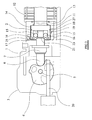
- Figure 1 is a cut away view of a locking switch mechanism in accordance with the present invention with the switch in an unlocked position;
- Figure 2 is a cut away view of a locking switch mechanism in accordance with the present invention with the switch in its locked position; and
- Figure 3 is a cut away perspective view of the switch mechanism of Figures 1 and 2 to an enlarged scale.
- Referring to Figure 1, the illustrated lockable switch mechanism comprises a
housing 1 in which aplunger 2 is slidable and which supports ahead assembly 3 supporting arotatable cam 4, thecam 4 being rotatable about apin 5. Theplunger 2 comprises a metal core supporting anouter casing 6 which is slidably received in a sealingcap 7. Theplunger 2 is symmetrical about is longitudinal axis and is slidable relative to thehousing 1 along that axis. - The end of the
plunger 2 remote from thecam 4 is received in abore 8, acompression spring 9 being located with thebore 8 so as to bias theplunger 2 in the direction indicated byarrow 10. Thebore 8 is formed in the end of asolenoid plunger 11 which is received with asolenoid housing 12. Energisation of a solenoid winding (not shown) in thesolenoid housing 12 drives thesolenoid plunger 11 to the right in Figure 1. De-energisation of the solenoid results in thesolenoid plunger 11 being moved to the left in Figure 1 by a compression spring 13 (Figure 2) which is located between thesolenoid housing 12 and alocking fork 14 which is engaged in a groove extending around the end of thesolenoid plunger 11 in which thebore 8 is formed. - Two
locking pins 15 are positioned on either side of theplunger 2, thelocking pins 15 being biased bysprings 16 against theplunger 2. Thelocking pins 15 andsprings 16 are retained within a housing assembly made up from aframe 17 and acover plate 18. It will be seen that with theplunger 2 in the position shown in Figure 1 thepins 15 are held at a distance from the axis of theplunger 2 such that they obstruct the passage ofarms 19 supported by thelocking fork 14 in the direction of thearrow 10. Thelocking pins 15 are made of non-conductive material. - Figure 2 shows the assembly of Figure 1 after the insertion of an
actuator 20 into thehead assembly 3 so as to cause rotation of thecam 4. Such rotation of thecam 4 enables theplunger 2 to move towards thepin 5. As a result aprofile 21 in the form of an annular shoulder on theplunger 2 is moved to the left of thelocking pins 15. Thelocking pins 15 are biased towards each other so as to remain in contact with theplunger 2, thereby enabling thearms 19 of thelocking fork 14 to pass thelocking pins 15. - The
actuator 20 andcam 4 are shaped such that insertion of the actuator into thehead assembly 3 causes the cam to rotate from a datum position, that is the position of thecam 4 as shown in Figure 1. In known manner, the actuator defines projections (not shown) which engage in recesses defined by the cam 4 (as shown in Figure 2) so that once thecam 4 has been rotated from the datum position theactuator 20 cannot be withdrawn from thehead assembly 3 unless thecam 4 has been rotated back to the datum position. An actuator and cam mechanism of this general type is described inUS Patent No. 5,777,284 . - In the unlocked condition of Figure 1 the
solenoid plunger 11 has been moved to the position it assumes when the solenoid is energised and theplunger 2 is in the position in which it is displaced by thecam 4 as far as possible towards thesolenoid housing 12. As a result the spacing between thepins 15 is such that even if the solenoid is then deenergised thearms 19 cannot move past thepins 15. Thepins 15 therefore impose no restraint on the axial displacement of theplunger 2. In contrast, as shown in Figure 2, if thecam 4 is then rotated to displace theplunger 2 so that thepins 15 can drop down the profiledshoulder 21 defined by theplunger 2, thesprings 16 urge the locking pins 15 towards each other so as to engage behind theshoulder 21. De-energisation of the solenoid then results in thearms 19 being extended past thepins 15, restraining thepins 15 against movement away from each other. Any attempt therefore to drive theplunger 2 towards thesolenoid housing 12 will be resisted as a result of thepins 15 jamming between theprofile 21 and thearms 19. Theframe 17 carries a pair ofelectrical contacts arms 19 of the lockingfork 14. The locking fork is formed of a conductive material. It will also be noted that the locking fork has a defined region of weakness orfracture point 27 where thearms 19 connect with the main body of the lockingfork 14. In the illustrated embodiment the region of weakness is created by relieving the outer side of thefork arms 14 but the relieving could be to the other side or both sides. - In the unlocked position of the switch shown in Figure 1, the ends of the
arms 19 are spaced from thecontacts arms 19 make contact with a respective one of thecontacts - However, if a force is applied to the plunger when in the locking position by way of the actuator, the profile of the plunger will apply a force to the
pins 15 in a direction which will try to spread thelegs 15 of the locking fork. Provided that the applied force is less than the designed load bearing capacity of the locking member, then this spreading force is resisted. - The locking fork is made from a material that exhibits low ductility, but high strength so as to resist deformation under load. However, when the arms are loaded up to their design limit, they will fracture at the
fracture point 27. As a consequence the conduction path formed by thearms 19 of the locking fork will be broken and the monitoring circuit broken thereby signalling that the switch is no longer intact and that replacement is required. - This construction has the advantage that once the switch has been loaded up to its design limit it fails and there is an immediate indication of fracture in contrast to designs where the arms spread under load whilst remaining intact and resulting in an unquantifiable but significantly reduced holding force.
Claims (9)
- A lockable switch mechanism comprising a switch plunger which is mounted in a housing and is displaceable relative to the housing along a predetermined axis between a first unlocked position and a second locked position, a locking mechanism for locking the switch plunger in the second position, and a switch mechanism which is actuated by movement of the switch plunger between the first and second positions, wherein the locking mechanism comprises at least one first locking member which is biased against a surface of the switch plunger and at least one second locking member which is displaceable between locked and released positions, the surface of the switch plunger against which the first locking member is biased defining a profile arranged such that movement of the switch plunger from the second to the first position causes the profile to displace the first locking member, and the second locking member when in the locked position preventing displacement of the first locking member by the profile to thereby prevent movement of the plunger from the second to the first position, and further comprising a pair of electrical contacts for use in monitoring when the switch is in at least its locked position, and wherein the second locking member, when in the locked position, provides a conductive path between said pair of electrical contacts.
- A lockable switch mechanism as claimed in claim 1, wherein the second locking member includes a frangible element that will break at a predetermined loading thereby breaking the conductive path and signalling that the switch has been loaded up to it prescribed limit.
- A lockable switch mechanism as claimed in claim 1 or 2, wherein the second locking member comprises at least one locking arm.
- A mechanism as claimed in claim 1, 2 or 3 wherein the second locking member comprises a pair of locking arms which are displaceable in a direction parallel to the switch plunger axis and, when in the locked position, ends of the arms contact a respective one of said contacts.
- A mechanism as claimed in claim 4, wherein the locking arms extend from one end of a solenoid plunger which is arranged at one end of the switch plunger and is displaceable along the switch plunger axis by a solenoid winding within a solenoid housing.
- A mechanism as claimed in any one of claims 1 to 5, wherein the housing assembly comprises a frame which receives the first locking member and wherein the pair of electrical contacts are accommodated within the frame.
- A mechanism as claimed in anyone of claims 2 to 6, wherein the or each locking arm has a thinner frangible section.
- A mechanism as claimed in claim 7, wherein the thinner frangible section is provided by a v-section notch in the arm.
- A lockable switch mechanism substantially as hereinbefore described with reference to and as illustrated in the accompanying drawings.
Applications Claiming Priority (1)
| Application Number | Priority Date | Filing Date | Title |
|---|---|---|---|
| GBGB0513651.0A GB0513651D0 (en) | 2005-07-02 | 2005-07-02 | Lockable switch mechanism |
Publications (2)
| Publication Number | Publication Date |
|---|---|
| EP1739699A1 true EP1739699A1 (en) | 2007-01-03 |
| EP1739699B1 EP1739699B1 (en) | 2008-08-27 |
Family
ID=34856606
Family Applications (1)
| Application Number | Title | Priority Date | Filing Date |
|---|---|---|---|
| EP06253279A Ceased EP1739699B1 (en) | 2005-07-02 | 2006-06-23 | Lockable switch mechanism |
Country Status (4)
| Country | Link |
|---|---|
| US (1) | US7223927B2 (en) |
| EP (1) | EP1739699B1 (en) |
| DE (1) | DE602006002436D1 (en) |
| GB (1) | GB0513651D0 (en) |
Cited By (1)
| Publication number | Priority date | Publication date | Assignee | Title |
|---|---|---|---|---|
| EP2026367A3 (en) * | 2007-08-16 | 2010-05-19 | Rockwell Automation Limited | Safety switch |
Families Citing this family (8)
| Publication number | Priority date | Publication date | Assignee | Title |
|---|---|---|---|---|
| US7442888B2 (en) * | 2005-08-22 | 2008-10-28 | Scientific Technologies Incorporated | Safety lock for interlock switch |
| JP4710648B2 (en) * | 2006-02-23 | 2011-06-29 | オムロン株式会社 | Safety switch |
| JP4747888B2 (en) * | 2006-03-09 | 2011-08-17 | オムロン株式会社 | switch |
| DE502006007966D1 (en) * | 2006-07-03 | 2010-11-11 | Siemens Ag | position switch |
| DE102008057223A1 (en) * | 2008-11-06 | 2010-05-20 | Euchner Gmbh + Co. Kg | Device for monitoring the state of a protective device of a machine |
| US8598477B2 (en) | 2009-10-13 | 2013-12-03 | Barton L. Garvin | Universal switch restraint device |
| US8937259B2 (en) | 2009-10-13 | 2015-01-20 | Barton L. Garvin | Universal electrical circuit breaker locking device |
| KR102517942B1 (en) * | 2021-08-12 | 2023-04-05 | 주식회사 오토닉스 | Door lock device |
Citations (3)
| Publication number | Priority date | Publication date | Assignee | Title |
|---|---|---|---|---|
| CH501303A (en) * | 1969-12-18 | 1970-12-31 | Sprecher & Schuh Ag | Electrical switching device with a latching device for the movable contact piece |
| US5062668A (en) * | 1989-04-13 | 1991-11-05 | Ellenberger & Poensgen Gmbh | Safety lock for the doors of electrical applicances |
| EP1376632A1 (en) * | 2002-06-19 | 2004-01-02 | Eja Limited | Lockable switch mechanism |
Family Cites Families (5)
| Publication number | Priority date | Publication date | Assignee | Title |
|---|---|---|---|---|
| DE3100862C2 (en) | 1981-01-14 | 1984-02-09 | K.A. Schmersal Gmbh & Co, 5600 Wuppertal | Safety switch |
| DE19602690C1 (en) * | 1996-01-26 | 1997-04-10 | Euchner & Co | Safety interlock switch e.g. for machine system safety door |
| FR2755533B1 (en) * | 1996-11-04 | 1998-12-24 | Schneider Electric Sa | SAFETY SWITCH WITH SWIVELING HEAD |
| JP3982143B2 (en) * | 2000-03-15 | 2007-09-26 | オムロン株式会社 | Lock switch device |
| FR2862810B1 (en) * | 2003-11-21 | 2006-01-06 | Schneider Electric Ind Sas | SAFETY POSITION SWITCH |
-
2005
- 2005-07-02 GB GBGB0513651.0A patent/GB0513651D0/en not_active Ceased
-
2006
- 2006-06-23 EP EP06253279A patent/EP1739699B1/en not_active Ceased
- 2006-06-23 DE DE602006002436T patent/DE602006002436D1/en active Active
- 2006-06-29 US US11/478,477 patent/US7223927B2/en active Active
Patent Citations (3)
| Publication number | Priority date | Publication date | Assignee | Title |
|---|---|---|---|---|
| CH501303A (en) * | 1969-12-18 | 1970-12-31 | Sprecher & Schuh Ag | Electrical switching device with a latching device for the movable contact piece |
| US5062668A (en) * | 1989-04-13 | 1991-11-05 | Ellenberger & Poensgen Gmbh | Safety lock for the doors of electrical applicances |
| EP1376632A1 (en) * | 2002-06-19 | 2004-01-02 | Eja Limited | Lockable switch mechanism |
Cited By (2)
| Publication number | Priority date | Publication date | Assignee | Title |
|---|---|---|---|---|
| EP2026367A3 (en) * | 2007-08-16 | 2010-05-19 | Rockwell Automation Limited | Safety switch |
| US8173914B2 (en) | 2007-08-16 | 2012-05-08 | Rockwell Automation Limited | Safety switch |
Also Published As
| Publication number | Publication date |
|---|---|
| GB0513651D0 (en) | 2005-08-10 |
| DE602006002436D1 (en) | 2008-10-09 |
| US7223927B2 (en) | 2007-05-29 |
| EP1739699B1 (en) | 2008-08-27 |
| US20070000765A1 (en) | 2007-01-04 |
Similar Documents
| Publication | Publication Date | Title |
|---|---|---|
| EP1739699B1 (en) | Lockable switch mechanism | |
| US8826709B2 (en) | Relocking mechanism | |
| KR101052388B1 (en) | Emergency push button | |
| RU2565154C2 (en) | Antitheft device for transport facility steering | |
| EP1376632B1 (en) | Lockable switch mechanism | |
| US8499596B2 (en) | Antitheft device for the steering column of a vehicle having superlockout provided by an intermediate rocker bar | |
| EP2176477A1 (en) | Lock which can be unlocked in an electrically automated manner, in particular for storage systems like lockers | |
| AT520540B1 (en) | Electromagnetic release | |
| EP1963599A1 (en) | A locking seal with tamper indication and notification device | |
| EP1876624B1 (en) | Safety switch | |
| EP2026367B1 (en) | Safety switch | |
| DE102012018080A1 (en) | Electro-mechanical interlock for use with device for protecting e.g. goods, has movable unit that is not blocked in degree of freedom by enable signal and locking mechanism that is executed resilient and is fitted with springs | |
| DE112010003693B4 (en) | safety switch | |
| EP2136019B1 (en) | Sub-assembly for blocking or releasing a door lock | |
| DE3421572C2 (en) | Safety device for detonators of small missile warheads | |
| EP3690909B1 (en) | Safety switch | |
| DE19937947A1 (en) | Electrical connection switching device for protection device status indication, has indicator that detects the switching of a protection device between states | |
| JP2007529363A (en) | Cylinder lock with coded key to secure the steering wheel shaft and prevent car theft | |
| DE102005001355B4 (en) | Batch work for safekeeping containers | |
| WO2019117742A2 (en) | Locking device for controlled locking and unlocking of authorized objects | |
| EP4105529A1 (en) | Trigger device and an assembly comprising a trigger device | |
| EP3802997B1 (en) | A cylinder lock with enhanced security against break-in attempts | |
| DE19542682C2 (en) | Safety device for detonators of small rocket warheads | |
| EP2047494B1 (en) | Safety switching device for interlocking a protection device | |
| US20080223092A1 (en) | Electromagnetic Lock Provided with a Sliding Bolt for a Swinging-Type Door |
Legal Events
| Date | Code | Title | Description |
|---|---|---|---|
| PUAI | Public reference made under article 153(3) epc to a published international application that has entered the european phase |
Free format text: ORIGINAL CODE: 0009012 |
|
| AK | Designated contracting states |
Kind code of ref document: A1 Designated state(s): AT BE BG CH CY CZ DE DK EE ES FI FR GB GR HU IE IS IT LI LT LU LV MC NL PL PT RO SE SI SK TR |
|
| AX | Request for extension of the european patent |
Extension state: AL BA HR MK YU |
|
| 17P | Request for examination filed |
Effective date: 20070522 |
|
| AKX | Designation fees paid |
Designated state(s): DE FR GB IT |
|
| GRAP | Despatch of communication of intention to grant a patent |
Free format text: ORIGINAL CODE: EPIDOSNIGR1 |
|
| GRAS | Grant fee paid |
Free format text: ORIGINAL CODE: EPIDOSNIGR3 |
|
| GRAA | (expected) grant |
Free format text: ORIGINAL CODE: 0009210 |
|
| AK | Designated contracting states |
Kind code of ref document: B1 Designated state(s): DE FR GB IT |
|
| REG | Reference to a national code |
Ref country code: GB Ref legal event code: FG4D |
|
| REF | Corresponds to: |
Ref document number: 602006002436 Country of ref document: DE Date of ref document: 20081009 Kind code of ref document: P |
|
| RAP2 | Party data changed (patent owner data changed or rights of a patent transferred) |
Owner name: ROCKWELL AUTOMATION LIMITED |
|
| PLBE | No opposition filed within time limit |
Free format text: ORIGINAL CODE: 0009261 |
|
| STAA | Information on the status of an ep patent application or granted ep patent |
Free format text: STATUS: NO OPPOSITION FILED WITHIN TIME LIMIT |
|
| 26N | No opposition filed |
Effective date: 20090528 |
|
| PG25 | Lapsed in a contracting state [announced via postgrant information from national office to epo] |
Ref country code: IT Free format text: LAPSE BECAUSE OF FAILURE TO SUBMIT A TRANSLATION OF THE DESCRIPTION OR TO PAY THE FEE WITHIN THE PRESCRIBED TIME-LIMIT Effective date: 20080827 |
|
| REG | Reference to a national code |
Ref country code: FR Ref legal event code: PLFP Year of fee payment: 10 |
|
| REG | Reference to a national code |
Ref country code: FR Ref legal event code: PLFP Year of fee payment: 11 |
|
| REG | Reference to a national code |
Ref country code: FR Ref legal event code: PLFP Year of fee payment: 12 |
|
| REG | Reference to a national code |
Ref country code: FR Ref legal event code: PLFP Year of fee payment: 13 |
|
| PGFP | Annual fee paid to national office [announced via postgrant information from national office to epo] |
Ref country code: FR Payment date: 20200520 Year of fee payment: 15 Ref country code: DE Payment date: 20200519 Year of fee payment: 15 |
|
| PGFP | Annual fee paid to national office [announced via postgrant information from national office to epo] |
Ref country code: GB Payment date: 20200525 Year of fee payment: 15 |
|
| REG | Reference to a national code |
Ref country code: DE Ref legal event code: R119 Ref document number: 602006002436 Country of ref document: DE |
|
| GBPC | Gb: european patent ceased through non-payment of renewal fee |
Effective date: 20210623 |
|
| PG25 | Lapsed in a contracting state [announced via postgrant information from national office to epo] |
Ref country code: GB Free format text: LAPSE BECAUSE OF NON-PAYMENT OF DUE FEES Effective date: 20210623 Ref country code: DE Free format text: LAPSE BECAUSE OF NON-PAYMENT OF DUE FEES Effective date: 20220101 |
|
| PG25 | Lapsed in a contracting state [announced via postgrant information from national office to epo] |
Ref country code: FR Free format text: LAPSE BECAUSE OF NON-PAYMENT OF DUE FEES Effective date: 20210630 |