EP1739627A1 - Method and apparatus for displaying a color flow image in an ultrasound diagnostic system - Google Patents
Method and apparatus for displaying a color flow image in an ultrasound diagnostic system Download PDFInfo
- Publication number
- EP1739627A1 EP1739627A1 EP06013069A EP06013069A EP1739627A1 EP 1739627 A1 EP1739627 A1 EP 1739627A1 EP 06013069 A EP06013069 A EP 06013069A EP 06013069 A EP06013069 A EP 06013069A EP 1739627 A1 EP1739627 A1 EP 1739627A1
- Authority
- EP
- European Patent Office
- Prior art keywords
- image
- color flow
- dimensional color
- flow image
- region
- Prior art date
- Legal status (The legal status is an assumption and is not a legal conclusion. Google has not performed a legal analysis and makes no representation as to the accuracy of the status listed.)
- Granted
Links
Images


Classifications
-
- A—HUMAN NECESSITIES
- A61—MEDICAL OR VETERINARY SCIENCE; HYGIENE
- A61B—DIAGNOSIS; SURGERY; IDENTIFICATION
- A61B8/00—Diagnosis using ultrasonic, sonic or infrasonic waves
-
- G—PHYSICS
- G06—COMPUTING OR CALCULATING; COUNTING
- G06T—IMAGE DATA PROCESSING OR GENERATION, IN GENERAL
- G06T19/00—Manipulating three-dimensional [3D] models or images for computer graphics
- G06T19/20—Editing of three-dimensional [3D] images, e.g. changing shapes or colours, aligning objects or positioning parts
-
- A—HUMAN NECESSITIES
- A61—MEDICAL OR VETERINARY SCIENCE; HYGIENE
- A61B—DIAGNOSIS; SURGERY; IDENTIFICATION
- A61B8/00—Diagnosis using ultrasonic, sonic or infrasonic waves
- A61B8/06—Measuring blood flow
-
- A—HUMAN NECESSITIES
- A61—MEDICAL OR VETERINARY SCIENCE; HYGIENE
- A61B—DIAGNOSIS; SURGERY; IDENTIFICATION
- A61B8/00—Diagnosis using ultrasonic, sonic or infrasonic waves
- A61B8/48—Diagnostic techniques
- A61B8/483—Diagnostic techniques involving the acquisition of a 3D volume of data
-
- G—PHYSICS
- G06—COMPUTING OR CALCULATING; COUNTING
- G06T—IMAGE DATA PROCESSING OR GENERATION, IN GENERAL
- G06T15/00—Three-dimensional [3D] image rendering
- G06T15/50—Lighting effects
- G06T15/503—Blending, e.g. for anti-aliasing
-
- G—PHYSICS
- G06—COMPUTING OR CALCULATING; COUNTING
- G06T—IMAGE DATA PROCESSING OR GENERATION, IN GENERAL
- G06T2210/00—Indexing scheme for image generation or computer graphics
- G06T2210/24—Fluid dynamics
-
- G—PHYSICS
- G06—COMPUTING OR CALCULATING; COUNTING
- G06T—IMAGE DATA PROCESSING OR GENERATION, IN GENERAL
- G06T2210/00—Indexing scheme for image generation or computer graphics
- G06T2210/62—Semi-transparency
-
- G—PHYSICS
- G06—COMPUTING OR CALCULATING; COUNTING
- G06T—IMAGE DATA PROCESSING OR GENERATION, IN GENERAL
- G06T2219/00—Indexing scheme for manipulating 3D models or images for computer graphics
- G06T2219/20—Indexing scheme for editing of 3D models
- G06T2219/2012—Colour editing, changing, or manipulating; Use of colour codes
Definitions
- the present invention generally relates to ultrasound diagnostic systems, and more particularly to an apparatus and method for displaying a color flow image in an ultrasound diagnostic system.
- an ultrasound diagnostic system projects ultrasound signals from a surface of a target object toward a desired part within the target object. This is to obtain an ultrasound image of a soft tissue or blood flow by non-invasive means through using information of ultrasound echo signals from the target object.
- the ultrasound diagnostic system is advantageous since it is small in size and fairly inexpensive.
- the ultrasound diagnostic system is capable of providing real-time display and is highly safe without any dangerous side effects such as exposure to X-rays, etc.
- it is extensively utilized for diagnosing the heart, abdomen and urinary organs, as well as being widely applied in the fields of obstetrics, gynecology, etc.
- the ultrasound diagnostic system forms ultrasound images of various modes (e.g., B-mode, M-mode, etc.) based on the ultrasound echo signals reflected from the target object. Also, the ultrasound diagnostic system can provide a color flow image, which indicates the velocities of a moving target object and scatters.
- the ultrasound diagnostic system displays the velocity and direction of blood flowing within a moving object (e.g., heart, blood vessel or the like) with various colors based on the Doppler shift of an ultrasound signal. For example, the conventional ultrasound diagnostic system indicates the blood flowing toward the transducer of the probe with a red color, while indicating the blood flowing backward from the transducer of the probe with a blue color. Furthermore, the conventional diagnostic system indicates a rapidly flowing blood with a light color, while indicating a slowly flowing blood with a dark color.
- the conventional diagnostic system displays the color Doppler image, which indicates the velocities of the moving target object and the scatters, on a 2-dimensional level, there is a problem in that a person unskilled in the conventional diagnostic system cannot accurately analyze the 2-dimensional color Doppler image.
- the conventional ultrasound diagnostic system superposes a plurality of 2-dimensional ultrasound images to provide a 3-dimensional color Doppler image. This is so that the above unskilled person can easily examine the target object through the displayed 3-dimensional color Doppler image.
- the 2-dimensional color Doppler images indicating different blood flows are superposed, then the colors indicating the blood flows are displayed while the images are superposed. Therefore, there is a problem in that the conventional ultrasound diagnostic system cannot provide accurate information of the blood flows.
- the present invention provides an apparatus and a method for performing a transparency treatment for blood flow images with predetermined transparency in the 3-dimensional color flow image to accurately display a target blood flow in an ultrasound diagnostic system.
- a method of displaying a color flow image comprising: a) forming a plurality of 2-dimensional color flow images based on ultrasound echo signals; b) sequentially superposing the plurality of 2-dimensional color flow images to form a 3-dimensional color flow image including a plurality of image regions; c) receiving selection information for selecting a desirable image region from the 3-dimensional color flow image; and d) performing a transparency treatment upon the selected region in the 3-dimensional color flow image to have a predetermined transparency.
- an apparatus for displaying a color flow image in an ultrasound diagnostic system comprising: an image forming unit for forming a plurality of 2-dimensional color flow images based on ultrasound echo signals and sequentially superposing the plurality of 2-dimensional color flow images to form a 3-dimensional color flow image including a plurality of image regions; a receiving unit for receiving selection information to select a desirable image region from the 3-dimensional color flow image; and a transparentizing unit for performing a transparency treatment upon the selected region in the 3-dimensional color flow image.
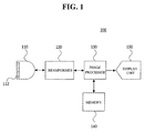
- Fig. 1 is a block diagram showing an ultrasound diagnostic system 100, which is constructed in accordance with the preferred embodiment of the present invention.
- the ultrasound diagnostic system 100 includes a probe 110, a beam former 120, an image processor 130, a memory 140 and a display unit 150.
- the probe 110 includes a 1-dimensional or 2-dimensional array transducer 112.
- the transmit signals which are appropriately delayed to form a focused ultrasound beam in the beam former 120, are transmitted to the array transducer 112 and the focused ultrasound beam is transmitted along a scan line of a target object (not shown).
- the probe 110 receives ultrasound echo signals reflected from the target object and converts the ultrasound echo signals into electric signals (hereinafter referred to as reception signals).
- reception signals are transmitted into the beam former 120.
- the beam former 120 controls the delay of transmit signals to be transmitted to the array transducer 112 in the probe 110 such that the ultrasound signals outputted from the array transducer 112 are focused on a focal point. Further, the beam former 120 focuses the reception signals received at the array transducer 112 included in the probe 110 in consideration of the delays with which the ultrasound echo signals arrived at each transducer.
- the image processor 130 sequentially superposes a plurality of 2-dimensional color flow images, which are formed based on the reception signals outputted from the beam former 120, to form a 3-dimensional color flow image containing blood flow images.
- the 3-dimensioanl color flow image includes a plurality of image regions and each region is differently colored.
- the image processor 130 performs a transparency treatment for a blood flow image region selected by a user to have a predetermined transparency.
- the 3-dimensional color flow image, which is processed. in the image processor 130 may be stored in the memory 140 or displayed on the display unit 150 according to the selection of the user.
- Fig. 2 is a flow chart showing the operation of the image processor, which is constructed in accordance with the present invention.
- the image processor 130 forms the plurality of 2-dimensional color Doppler image based on the focused reception signals outputted from the beam former 120 at step S110.
- the reception signals include color information of the target object.
- the image processor 130 checks whether a 3D mode is selected at step S120. If it is determined that the 3D mode is selected at step S120, then the image processor 130 sequentially superposes the plurality of 2-dimensional color flow images so as to form the 3-dimensioanl color flow image at step S 130.
- the 3-dimensional color ultrasound image 310 includes a plurality of image regions and each region is differently colored.
- the 3-dimensional color ultrasound image 310 and color maps 322 and 332 corresponding to blood flow images 321 and 331, which are examples formed in the image processor 130, are shown in Fig. 3.
- the image processor 130 checks whether a region, which is processed with transparency, is selected based on selection information inputted from the user at step S 140.
- the selected region may correspond to a region, which the user does not wish to observe.
- the selection of the region is carried out by selecting one of the color maps 322 and 332 or one of the colors within the color maps 322 and 332.
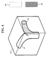
- the image processor 130 performs the transparency treatment for a color of a blood flow in the selected region so as to have a predetermined transparency at step S 150. For example, if the color map 322 corresponding to the blood flow image 130 is selected as a region to be transparentized, then the image processor 130 assigns a transparent color having the predetermined transparency to the color indicating the blood flow image 321 and color map 322. Consequently, the color indicating the blood flow image 321 and color map 322 are transparentized, as shown in Fig. 4.
- the region selected by the user is transparentized as a region that is not to be observed.
- the regions, which are not selected by the user may be set as regions that are not to be observed. This is so that the transparency treatment may be performed to the regions with the exception of the selected regions in accordance with another embodiment of the present invention.
- the transparency treatment is selectively carried out for colors corresponding to the blood flow images that are superposed, the blood flow image to be observed can be separately displayed. This is so that the user can accurately examine the blood flow image that the user wishes to observe.
Landscapes
- Health & Medical Sciences (AREA)
- Engineering & Computer Science (AREA)
- Life Sciences & Earth Sciences (AREA)
- Physics & Mathematics (AREA)
- Biophysics (AREA)
- Surgery (AREA)
- Veterinary Medicine (AREA)
- Public Health (AREA)
- General Health & Medical Sciences (AREA)
- Animal Behavior & Ethology (AREA)
- Molecular Biology (AREA)
- Medical Informatics (AREA)
- Heart & Thoracic Surgery (AREA)
- Nuclear Medicine, Radiotherapy & Molecular Imaging (AREA)
- Pathology (AREA)
- Radiology & Medical Imaging (AREA)
- Biomedical Technology (AREA)
- Computer Graphics (AREA)
- Theoretical Computer Science (AREA)
- General Physics & Mathematics (AREA)
- Architecture (AREA)
- Hematology (AREA)
- Software Systems (AREA)
- Computer Hardware Design (AREA)
- General Engineering & Computer Science (AREA)
- Ultra Sonic Daignosis Equipment (AREA)
Abstract
Description
- The present invention generally relates to ultrasound diagnostic systems, and more particularly to an apparatus and method for displaying a color flow image in an ultrasound diagnostic system.
- Generally, an ultrasound diagnostic system projects ultrasound signals from a surface of a target object toward a desired part within the target object. This is to obtain an ultrasound image of a soft tissue or blood flow by non-invasive means through using information of ultrasound echo signals from the target object.
Compared to other medical imaging systems (e.g., X-ray diagnostic system, X-ray CT scanner, MRI and nuclear medicine diagnostic system), the ultrasound diagnostic system is advantageous since it is small in size and fairly inexpensive. Further, the ultrasound diagnostic system is capable of providing real-time display and is highly safe without any dangerous side effects such as exposure to X-rays, etc. Thus, it is extensively utilized for diagnosing the heart, abdomen and urinary organs, as well as being widely applied in the fields of obstetrics, gynecology, etc. - The ultrasound diagnostic system forms ultrasound images of various modes (e.g., B-mode, M-mode, etc.) based on the ultrasound echo signals reflected from the target object. Also, the ultrasound diagnostic system can provide a color flow image, which indicates the velocities of a moving target object and scatters. The ultrasound diagnostic system displays the velocity and direction of blood flowing within a moving object (e.g., heart, blood vessel or the like) with various colors based on the Doppler shift of an ultrasound signal. For example, the conventional ultrasound diagnostic system indicates the blood flowing toward the transducer of the probe with a red color, while indicating the blood flowing backward from the transducer of the probe with a blue color. Furthermore, the conventional diagnostic system indicates a rapidly flowing blood with a light color, while indicating a slowly flowing blood with a dark color.
- Since the conventional diagnostic system displays the color Doppler image, which indicates the velocities of the moving target object and the scatters, on a 2-dimensional level, there is a problem in that a person unskilled in the conventional diagnostic system cannot accurately analyze the 2-dimensional color Doppler image.
- In order to overcome the above problem, the conventional ultrasound diagnostic system superposes a plurality of 2-dimensional ultrasound images to provide a 3-dimensional color Doppler image. This is so that the above unskilled person can easily examine the target object through the displayed 3-dimensional color Doppler image. However, if the 2-dimensional color Doppler images indicating different blood flows are superposed, then the colors indicating the blood flows are displayed while the images are superposed. Therefore, there is a problem in that the conventional ultrasound diagnostic system cannot provide accurate information of the blood flows.
- The present invention provides an apparatus and a method for performing a transparency treatment for blood flow images with predetermined transparency in the 3-dimensional color flow image to accurately display a target blood flow in an ultrasound diagnostic system.
- In accordance with one aspect of the present invention, there is provided a method of displaying a color flow image, comprising: a) forming a plurality of 2-dimensional color flow images based on ultrasound echo signals; b) sequentially superposing the plurality of 2-dimensional color flow images to form a 3-dimensional color flow image including a plurality of image regions; c) receiving selection information for selecting a desirable image region from the 3-dimensional color flow image; and d) performing a transparency treatment upon the selected region in the 3-dimensional color flow image to have a predetermined transparency.
- In accordance with another aspect of the present invention, there is provided an apparatus for displaying a color flow image in an ultrasound diagnostic system, comprising: an image forming unit for forming a plurality of 2-dimensional color flow images based on ultrasound echo signals and sequentially superposing the plurality of 2-dimensional color flow images to form a 3-dimensional color flow image including a plurality of image regions; a receiving unit for receiving selection information to select a desirable image region from the 3-dimensional color flow image; and a transparentizing unit for performing a transparency treatment upon the selected region in the 3-dimensional color flow image.
- The above and other objects and features of the present invention will become apparent from the following description of preferred embodiments given in conjunction with the accompanying drawings, in which:
- Fig. 1 is a block diagram showing an ultrasound diagnostic system constructed in accordance with the preferred embodiment of the present invention;
- Fig. 2 is a flow chart showing an operation of the image processor constructed in accordance with the present invention;
- Fig. 3 is a diagram showing a 3-dimensional color flow image formed in accordance with the present invention; and
- Fig. 4 is a diagram showing a 3-dimensional color flow image in which a selected blood flow image is transparentized.
- Fig. 1 is a block diagram showing an ultrasound
diagnostic system 100, which is constructed in accordance with the preferred embodiment of the present invention. As shown in Fig. 1, the ultrasounddiagnostic system 100 includes aprobe 110, a beam former 120, animage processor 130, amemory 140 and adisplay unit 150. - The
probe 110 includes a 1-dimensional or 2-dimensional array transducer 112. The transmit signals, which are appropriately delayed to form a focused ultrasound beam in the beam former 120, are transmitted to thearray transducer 112 and the focused ultrasound beam is transmitted along a scan line of a target object (not shown). Theprobe 110 receives ultrasound echo signals reflected from the target object and converts the ultrasound echo signals into electric signals (hereinafter referred to as reception signals). The reception signals are transmitted into the beam former 120. - The beam former 120 controls the delay of transmit signals to be transmitted to the
array transducer 112 in theprobe 110 such that the ultrasound signals outputted from thearray transducer 112 are focused on a focal point. Further, thebeam former 120 focuses the reception signals received at thearray transducer 112 included in theprobe 110 in consideration of the delays with which the ultrasound echo signals arrived at each transducer. - The
image processor 130 sequentially superposes a plurality of 2-dimensional color flow images, which are formed based on the reception signals outputted from thebeam former 120, to form a 3-dimensional color flow image containing blood flow images. The 3-dimensioanl color flow image includes a plurality of image regions and each region is differently colored. Theimage processor 130 performs a transparency treatment for a blood flow image region selected by a user to have a predetermined transparency. The 3-dimensional color flow image, which is processed. in theimage processor 130, may be stored in thememory 140 or displayed on thedisplay unit 150 according to the selection of the user. - Hereinafter, the operation of the image processor will be described in detail in view of Figs. 2 to 4. Fig. 2 is a flow chart showing the operation of the image processor, which is constructed in accordance with the present invention. As shown in Fig. 2, the
image processor 130 forms the plurality of 2-dimensional color Doppler image based on the focused reception signals outputted from the beam former 120 at step S110. The reception signals include color information of the target object. - The
image processor 130 checks whether a 3D mode is selected at step S120. If it is determined that the 3D mode is selected at step S120, then theimage processor 130 sequentially superposes the plurality of 2-dimensional color flow images so as to form the 3-dimensioanl color flow image atstep S 130. The 3-dimensionalcolor ultrasound image 310 includes a plurality of image regions and each region is differently colored. The 3-dimensionalcolor ultrasound image 310 andcolor maps blood flow images image processor 130, are shown in Fig. 3. - Subsequently, the
image processor 130 checks whether a region, which is processed with transparency, is selected based on selection information inputted from the user atstep S 140. The selected region may correspond to a region, which the user does not wish to observe. In such a case, the selection of the region is carried out by selecting one of thecolor maps color maps - If it is determined that the region to be processed with the transparency is selected at step S150, then the
image processor 130 performs the transparency treatment for a color of a blood flow in the selected region so as to have a predetermined transparency atstep S 150. For example, if thecolor map 322 corresponding to theblood flow image 130 is selected as a region to be transparentized, then theimage processor 130 assigns a transparent color having the predetermined transparency to the color indicating theblood flow image 321 andcolor map 322. Consequently, the color indicating theblood flow image 321 andcolor map 322 are transparentized, as shown in Fig. 4. - According to the preferred embodiment of the present invention, the region selected by the user is transparentized as a region that is not to be observed. However, the regions, which are not selected by the user, may be set as regions that are not to be observed. This is so that the transparency treatment may be performed to the regions with the exception of the selected regions in accordance with another embodiment of the present invention.
- As the transparency treatment is selectively carried out for colors corresponding to the blood flow images that are superposed, the blood flow image to be observed can be separately displayed. This is so that the user can accurately examine the blood flow image that the user wishes to observe.
- While the present invention has been described and illustrated with respect to a preferred embodiment of the invention, it will be apparent to those skilled in the art that variations and modifications are possible without deviating from the broad principles and teachings of the present invention which should be limited solely by the scope of the claims appended hereto.
Claims (6)
- A method of displaying a color flow image, comprising the steps of:a) forming a plurality of 2-dimensional color flow images based on ultrasound echo signals;b) sequentially superposing the plurality of 2-dimensional color flow images to form a 3-dimensional color flow image including a plurality of image regions;c) receiving selection information for selecting a desirable image region from the 3-dimensional color flow image; andd) performing a transparency treatment upon the selected image region in the 3-dimensional color flow image to have a predetermined transparency.
- The method of Claim 1, wherein the step b) includes forming a plurality of color maps corresponding to the 3-dimensional color flow image.
- The method of Claim 2, wherein the step c) is carried out by selecting one of the color maps or one of colors within the color maps.
- An apparatus for displaying a color flow image in an ultrasound diagnostic system, comprising:an image forming unit for forming a plurality of 2-dimensional color flow images based on ultrasound echo signals and sequentially superposing the plurality of 2-dimensional color flow images to form a 3-dimensional color flow image including a plurality of image regions;a receiving unit for receiving selection information to select a desirable region from the 3-dimensional color flow image; anda transparentizing unit for performing a transparency treatment upon the selected region in the 3-dimensional color flow image.
- The apparatus of Claim 4, wherein the image forming unit further forms color maps corresponding to the 3-dimensional color flow image.
- The apparatus of Claim 5, wherein the region selection is carried out by selecting one of the color maps or one of colors within the color maps.
Applications Claiming Priority (1)
| Application Number | Priority Date | Filing Date | Title |
|---|---|---|---|
| KR1020050056011A KR100825054B1 (en) | 2005-06-28 | 2005-06-28 | How to image color flow images and ultrasound diagnostic system |
Publications (2)
| Publication Number | Publication Date |
|---|---|
| EP1739627A1 true EP1739627A1 (en) | 2007-01-03 |
| EP1739627B1 EP1739627B1 (en) | 2010-01-20 |
Family
ID=36821501
Family Applications (1)
| Application Number | Title | Priority Date | Filing Date |
|---|---|---|---|
| EP06013069A Ceased EP1739627B1 (en) | 2005-06-28 | 2006-06-24 | Method and apparatus for displaying a color flow image in an ultrasound diagnostic system |
Country Status (5)
| Country | Link |
|---|---|
| US (1) | US7621872B2 (en) |
| EP (1) | EP1739627B1 (en) |
| JP (1) | JP2007007402A (en) |
| KR (1) | KR100825054B1 (en) |
| DE (1) | DE602006011823D1 (en) |
Families Citing this family (12)
| Publication number | Priority date | Publication date | Assignee | Title |
|---|---|---|---|---|
| KR100825054B1 (en) | 2005-06-28 | 2008-04-28 | 주식회사 메디슨 | How to image color flow images and ultrasound diagnostic system |
| KR100769546B1 (en) * | 2005-06-28 | 2007-10-31 | 주식회사 메디슨 | 3D ultrasound image forming method and ultrasonic diagnostic system using 2D ultrasound image |
| KR101055500B1 (en) * | 2007-11-14 | 2011-08-08 | 삼성메디슨 주식회사 | Ultrasound system and method for forming BC-mode images |
| KR101055580B1 (en) | 2007-11-14 | 2011-08-23 | 삼성메디슨 주식회사 | Ultrasound system and method for forming BC-mode images |
| KR101024851B1 (en) * | 2007-12-04 | 2011-03-31 | 주식회사 메디슨 | Ultrasound system and method for forming BC-mode images |
| WO2011086774A1 (en) * | 2010-01-18 | 2011-07-21 | 株式会社 日立メディコ | Ultrasonic diagnostic device and ultrasonic image display method |
| US8988462B2 (en) * | 2010-02-09 | 2015-03-24 | Hitachi Medical Corporation | Ultrasonic diagnostic apparatus and ultrasonic image display method |
| KR101117879B1 (en) * | 2010-05-27 | 2012-03-07 | 삼성메디슨 주식회사 | Ultrasound system and method for providing color reconstruction image |
| KR101390186B1 (en) * | 2010-12-07 | 2014-04-29 | 삼성메디슨 주식회사 | Ultrasound system and method for providing additional information representing a change of blood flow over time |
| KR101406807B1 (en) | 2011-12-28 | 2014-06-12 | 삼성메디슨 주식회사 | Ultrasound system and method for providing user interface |
| US20150342569A1 (en) * | 2014-05-30 | 2015-12-03 | Siemens Medical Solutions Usa, Inc. | Transparency control for medical diagnostic ultrasound flow imaging |
| KR102700668B1 (en) * | 2017-01-10 | 2024-08-30 | 삼성메디슨 주식회사 | Apparatus and method for displaying an ultrasound image of the object |
Citations (1)
| Publication number | Priority date | Publication date | Assignee | Title |
|---|---|---|---|---|
| EP0797106A2 (en) * | 1996-03-22 | 1997-09-24 | Advanced Technology Laboratories, Inc. | Three dimensional medical ultrasonic diagnostic imaging of tissue texture and vasculature |
Family Cites Families (6)
| Publication number | Priority date | Publication date | Assignee | Title |
|---|---|---|---|---|
| US6511426B1 (en) * | 1998-06-02 | 2003-01-28 | Acuson Corporation | Medical diagnostic ultrasound system and method for versatile processing |
| US6245017B1 (en) * | 1998-10-30 | 2001-06-12 | Kabushiki Kaisha Toshiba | 3D ultrasonic diagnostic apparatus |
| US6352509B1 (en) * | 1998-11-16 | 2002-03-05 | Kabushiki Kaisha Toshiba | Three-dimensional ultrasonic diagnosis apparatus |
| JP4610011B2 (en) * | 2003-07-22 | 2011-01-12 | 株式会社日立メディコ | Ultrasonic diagnostic apparatus and ultrasonic image display method |
| KR100825054B1 (en) | 2005-06-28 | 2008-04-28 | 주식회사 메디슨 | How to image color flow images and ultrasound diagnostic system |
| KR100769546B1 (en) * | 2005-06-28 | 2007-10-31 | 주식회사 메디슨 | 3D ultrasound image forming method and ultrasonic diagnostic system using 2D ultrasound image |
-
2005
- 2005-06-28 KR KR1020050056011A patent/KR100825054B1/en not_active Expired - Fee Related
-
2006
- 2006-06-23 US US11/473,181 patent/US7621872B2/en active Active
- 2006-06-24 DE DE602006011823T patent/DE602006011823D1/en active Active
- 2006-06-24 EP EP06013069A patent/EP1739627B1/en not_active Ceased
- 2006-06-27 JP JP2006176317A patent/JP2007007402A/en active Pending
Patent Citations (1)
| Publication number | Priority date | Publication date | Assignee | Title |
|---|---|---|---|---|
| EP0797106A2 (en) * | 1996-03-22 | 1997-09-24 | Advanced Technology Laboratories, Inc. | Three dimensional medical ultrasonic diagnostic imaging of tissue texture and vasculature |
Non-Patent Citations (2)
| Title |
|---|
| JONES M G ET AL: "Visualisation of 4-D colour and power Doppler data", ULTRASOUND IN MEDICINE AND BIOLOGY, NEW YORK, NY, US, vol. 29, no. 12, December 2003 (2003-12-01), pages 1735 - 1747, XP004482541, ISSN: 0301-5629 * |
| TEISTLER M ET AL: "Visualization of echocardiographic data using virtual scenes", COMPUTERS IN CARDIOLOGY, 1999 HANNOVER, GERMANY 26-29 SEPT. 1999, PISCATAWAY, NJ, USA,IEEE, US, 26 September 1999 (1999-09-26), pages 399 - 402, XP010367055, ISBN: 0-7803-5614-4 * |
Also Published As
| Publication number | Publication date |
|---|---|
| US7621872B2 (en) | 2009-11-24 |
| US20070038104A1 (en) | 2007-02-15 |
| KR100825054B1 (en) | 2008-04-28 |
| KR20070000565A (en) | 2007-01-03 |
| JP2007007402A (en) | 2007-01-18 |
| DE602006011823D1 (en) | 2010-03-11 |
| EP1739627B1 (en) | 2010-01-20 |
Similar Documents
| Publication | Publication Date | Title |
|---|---|---|
| KR100748178B1 (en) | Ultrasound Diagnostic System and Method for Displaying Arbitrary M-Mode Images | |
| EP0797106B1 (en) | Three dimensional medical ultrasonic diagnostic imaging of tissue texture and vasculature | |
| JP5236655B2 (en) | 3D ultrasound color flow imaging using gray scale inversion | |
| US5865750A (en) | Method and apparatus for enhancing segmentation in three-dimensional ultrasound imaging | |
| KR101126851B1 (en) | Adaptive color doppler accomplishment method and ultrasound diagnostic system for the same | |
| US8160315B2 (en) | Ultrasonic imaging apparatus and projection image generating method | |
| US6814703B2 (en) | Apparatus and method for ultrasonic diagnostic imaging using a contrast medium | |
| JP7286025B2 (en) | Systems and methods for assessing placenta | |
| US20140187947A1 (en) | Ultrasound imaging system and method for identifying data from a shadow region | |
| EP1977694A1 (en) | Ultrasound system and method of forming an ultrasound image | |
| JP7090609B2 (en) | Ultrasound systems and methods for detecting kidney stones using twinkling artifacts | |
| US20060084870A1 (en) | Ultrasound diagnostic system for providing elastic image with additional information | |
| KR100948047B1 (en) | Ultrasound System and Method for Forming Ultrasound Images | |
| US7621872B2 (en) | Method and apparatus for displaying a color flow image in an ultrasound diagnostic system | |
| KR20070069322A (en) | Ultrasound diagnosis system and method for detecting lesion tissue | |
| CN110035701A (en) | Ultrasonic imaging method and the device for implementing the method | |
| US6350241B1 (en) | Method and apparatus for multiple angle compound flow imaging | |
| JP3936450B2 (en) | Projection image generation apparatus and medical image apparatus | |
| JP4978148B2 (en) | System and method for forming a three-dimensional image using multiple cross-sectional images | |
| US20070255138A1 (en) | Method and apparatus for 3D visualization of flow jets | |
| JP2005143733A (en) | Ultrasonic diagnostic apparatus, three-dimensional image data display apparatus, and three-dimensional image data display method | |
| KR100769546B1 (en) | 3D ultrasound image forming method and ultrasonic diagnostic system using 2D ultrasound image | |
| JP5053548B2 (en) | Ultrasonic diagnostic apparatus and control program for ultrasonic diagnostic apparatus | |
| JP2782905B2 (en) | Ultrasound diagnostic equipment | |
| JP2005006718A (en) | Ultrasonic diagnostic device |
Legal Events
| Date | Code | Title | Description |
|---|---|---|---|
| PUAI | Public reference made under article 153(3) epc to a published international application that has entered the european phase |
Free format text: ORIGINAL CODE: 0009012 |
|
| AK | Designated contracting states |
Kind code of ref document: A1 Designated state(s): AT BE BG CH CY CZ DE DK EE ES FI FR GB GR HU IE IS IT LI LT LU LV MC NL PL PT RO SE SI SK TR |
|
| AX | Request for extension of the european patent |
Extension state: AL BA HR MK YU |
|
| 17P | Request for examination filed |
Effective date: 20070525 |
|
| 17Q | First examination report despatched |
Effective date: 20070621 |
|
| AKX | Designation fees paid |
Designated state(s): DE FR IT |
|
| GRAP | Despatch of communication of intention to grant a patent |
Free format text: ORIGINAL CODE: EPIDOSNIGR1 |
|
| GRAS | Grant fee paid |
Free format text: ORIGINAL CODE: EPIDOSNIGR3 |
|
| GRAA | (expected) grant |
Free format text: ORIGINAL CODE: 0009210 |
|
| AK | Designated contracting states |
Kind code of ref document: B1 Designated state(s): DE FR IT |
|
| REF | Corresponds to: |
Ref document number: 602006011823 Country of ref document: DE Date of ref document: 20100311 Kind code of ref document: P |
|
| PLBE | No opposition filed within time limit |
Free format text: ORIGINAL CODE: 0009261 |
|
| STAA | Information on the status of an ep patent application or granted ep patent |
Free format text: STATUS: NO OPPOSITION FILED WITHIN TIME LIMIT |
|
| 26N | No opposition filed |
Effective date: 20101021 |
|
| REG | Reference to a national code |
Ref country code: FR Ref legal event code: PLFP Year of fee payment: 11 |
|
| REG | Reference to a national code |
Ref country code: FR Ref legal event code: PLFP Year of fee payment: 12 |
|
| REG | Reference to a national code |
Ref country code: FR Ref legal event code: PLFP Year of fee payment: 13 |
|
| PGFP | Annual fee paid to national office [announced via postgrant information from national office to epo] |
Ref country code: DE Payment date: 20240507 Year of fee payment: 19 |
|
| PGFP | Annual fee paid to national office [announced via postgrant information from national office to epo] |
Ref country code: IT Payment date: 20240508 Year of fee payment: 19 Ref country code: FR Payment date: 20240508 Year of fee payment: 19 |
|
| REG | Reference to a national code |
Ref country code: DE Ref legal event code: R119 Ref document number: 602006011823 Country of ref document: DE |
|
| PG25 | Lapsed in a contracting state [announced via postgrant information from national office to epo] |
Ref country code: DE Free format text: LAPSE BECAUSE OF NON-PAYMENT OF DUE FEES Effective date: 20260101 |
|
| PG25 | Lapsed in a contracting state [announced via postgrant information from national office to epo] |
Ref country code: IT Free format text: LAPSE BECAUSE OF NON-PAYMENT OF DUE FEES Effective date: 20250624 |
|
| PG25 | Lapsed in a contracting state [announced via postgrant information from national office to epo] |
Ref country code: FR Free format text: LAPSE BECAUSE OF NON-PAYMENT OF DUE FEES Effective date: 20250630 |