EP1739623A1 - Hierarchical motion estimation method and ultrasound imaging system using the same - Google Patents
Hierarchical motion estimation method and ultrasound imaging system using the same Download PDFInfo
- Publication number
- EP1739623A1 EP1739623A1 EP06013450A EP06013450A EP1739623A1 EP 1739623 A1 EP1739623 A1 EP 1739623A1 EP 06013450 A EP06013450 A EP 06013450A EP 06013450 A EP06013450 A EP 06013450A EP 1739623 A1 EP1739623 A1 EP 1739623A1
- Authority
- EP
- European Patent Office
- Prior art keywords
- image
- motion estimation
- input image
- images
- motion
- Prior art date
- Legal status (The legal status is an assumption and is not a legal conclusion. Google has not performed a legal analysis and makes no representation as to the accuracy of the status listed.)
- Withdrawn
Links
- 0 *C1C=CC=C1 Chemical compound *C1C=CC=C1 0.000 description 1
Images




Classifications
-
- A—HUMAN NECESSITIES
- A61—MEDICAL OR VETERINARY SCIENCE; HYGIENE
- A61B—DIAGNOSIS; SURGERY; IDENTIFICATION
- A61B8/00—Diagnosis using ultrasonic, sonic or infrasonic waves
- A61B8/08—Clinical applications
-
- G—PHYSICS
- G06—COMPUTING OR CALCULATING; COUNTING
- G06T—IMAGE DATA PROCESSING OR GENERATION, IN GENERAL
- G06T7/00—Image analysis
- G06T7/20—Analysis of motion
- G06T7/207—Analysis of motion for motion estimation over a hierarchy of resolutions
-
- G—PHYSICS
- G06—COMPUTING OR CALCULATING; COUNTING
- G06T—IMAGE DATA PROCESSING OR GENERATION, IN GENERAL
- G06T7/00—Image analysis
- G06T7/20—Analysis of motion
- G06T7/215—Motion-based segmentation
-
- G—PHYSICS
- G06—COMPUTING OR CALCULATING; COUNTING
- G06T—IMAGE DATA PROCESSING OR GENERATION, IN GENERAL
- G06T7/00—Image analysis
- G06T7/20—Analysis of motion
- G06T7/246—Analysis of motion using feature-based methods, e.g. the tracking of corners or segments
-
- G—PHYSICS
- G06—COMPUTING OR CALCULATING; COUNTING
- G06T—IMAGE DATA PROCESSING OR GENERATION, IN GENERAL
- G06T7/00—Image analysis
- G06T7/30—Determination of transform parameters for the alignment of images, i.e. image registration
- G06T7/33—Determination of transform parameters for the alignment of images, i.e. image registration using feature-based methods
-
- G—PHYSICS
- G01—MEASURING; TESTING
- G01S—RADIO DIRECTION-FINDING; RADIO NAVIGATION; DETERMINING DISTANCE OR VELOCITY BY USE OF RADIO WAVES; LOCATING OR PRESENCE-DETECTING BY USE OF THE REFLECTION OR RERADIATION OF RADIO WAVES; ANALOGOUS ARRANGEMENTS USING OTHER WAVES
- G01S7/00—Details of systems according to groups G01S13/00, G01S15/00, G01S17/00
- G01S7/52—Details of systems according to groups G01S13/00, G01S15/00, G01S17/00 of systems according to group G01S15/00
- G01S7/52017—Details of systems according to groups G01S13/00, G01S15/00, G01S17/00 of systems according to group G01S15/00 particularly adapted to short-range imaging
- G01S7/52053—Display arrangements
- G01S7/52057—Cathode ray tube displays
- G01S7/5206—Two-dimensional coordinated display of distance and direction; B-scan display
- G01S7/52065—Compound scan display, e.g. panoramic imaging
-
- G—PHYSICS
- G06—COMPUTING OR CALCULATING; COUNTING
- G06T—IMAGE DATA PROCESSING OR GENERATION, IN GENERAL
- G06T2207/00—Indexing scheme for image analysis or image enhancement
- G06T2207/10—Image acquisition modality
- G06T2207/10132—Ultrasound image
-
- G—PHYSICS
- G06—COMPUTING OR CALCULATING; COUNTING
- G06T—IMAGE DATA PROCESSING OR GENERATION, IN GENERAL
- G06T2207/00—Indexing scheme for image analysis or image enhancement
- G06T2207/30—Subject of image; Context of image processing
- G06T2207/30004—Biomedical image processing
- G06T2207/30088—Skin; Dermal
Definitions
- the present invention generally relates to a method of forming ultrasound images and a system using the same, and more particularly to a method of estimating hierarchical motion for accurately estimating real-time motion from a sequence of ultrasound images and an ultrasound imaging system using the same.
- Ultrasound imaging is a non-invasive technique typically used for examining internal organs. Ultrasound imaging is performed by sending ultrasound waves into the body. The reflected ultrasound waves are recorded and then displayed as a real-time visual image. Since the ultrasound images are displayed in real time, they can show the movements of internal tissues, organs and blood flow.
- the ultrasound images are used in various medical applications.
- wide-view images i.e., panoramic images
- panoramic images display the organs and their adjacent anatomical features in one single image, thereby eliminating the need for physicians to mentally piece together a complete picture of anatomical structures.
- the panoramic images can display both lobes of the thyroid gland on a single image to thereby provide an accurate image representation of various thyroid disorders.
- the known techniques for estimating motion include the gradient technique, pel-recursive technique, block matching technique, etc.
- the motion is estimated for every pixel in order to obtain motion information.
- the block matching technique is more widely used than the above techniques.
- the arrangement and sizes of the blocks affect the performance of motion estimation. Specifically, the arrangement of blocks affects the estimation variance of global motion components, whereas the sizes of blocks influence the amount of calculation. In the global motion estimation, it is important to regularly arrange the blocks in their respective motion estimation areas.
- the present invention provides a method of estimating hierarchical motion to accurately display a sequence of images in real time by decreasing an amount of calculation for processing sequential images as well as to reduce an error in global motion estimation. Further, the present invention provides an ultrasound imaging system that uses such hierarchical motion estimation method.
- a hierarchical motion estimation method which includes the following steps: (1) decomposing first and second input images into at least two hierarchical, multi-resolution images; (2) selecting one of the multi-resolution images decomposed from the second input image, dividing the selected image into at least two motion estimation areas and extracting feature points from the motion estimation areas; (3) arranging blocks with specified sizes to surround the extracted feature points; and (4) estimating local motions of the blocks by matching the second input image with the first input image and predicting a global motion in the motion estimation areas.
- an ultrasound imaging system which includes the following: (1) an image decomposition unit for decomposing first and second ultrasound input images into at least two hierarchical, multi-resolution images; (2) a feature extraction unit for selecting one of the multi-resolution images decomposed from the second input image, the feature extraction unit further being configured to divide the selected image into at least two motion estimation areas and extract feature points from the motion estimation areas; (3) a block arrangement unit for arranging blocks with specified sizes to surround the extracted feature points; and (4) a motion estimation unit for estimating local motions of the blocks by matching the second input image with the first input image to predict a global motion in the motion estimation areas.
- the blocks are arranged so as to be separated from each other.
- the feature points may be extracted from an image having the lowest resolution.
- the input image may be an ultrasound image, and the first and second input image may be sequential in time.
- a method for forming a panoramic image from sequential images by using hierarchical motion estimation in an ultrasound imaging system which includes the following steps: a) decomposing each of first and second input images occurring sequentially into at least two hierarchical multi-resolution images; b) dividing a lowest resolution image of the multi-resolution images decomposed from the second input image into at least two motion estimation areas and extracting feature points from the motion estimation areas, respectively; c) arranging blocks having a specified size to surround the extracted feature points, respectively; d) setting a search window on a lowest resolution image of the multi-resolution images decomposed from the first input image; e) matching the blocks with the lowest resolution image of the first input image within the search window to estimate local motion in the blocks; f) estimating global motion in the motion estimation areas by using the estimated local motion; and h) compounding the first and second input images on the basis of the estimated global motion to form a panoramic image.
- the calculation time can be decreased. Further, in accordance with the present invention, since the blocks are separately arranged after dividing into the motion estimation areas, the calculation time can be reduced without affecting accuracy.
- Fig. 1 is a block diagram showing the schematic configuration of an ultrasound imaging system, which is constructed in accordance with the preferred embodiment of the present invention.
- an ultrasound imaging system 400 includes: an image decomposition unit 410; a feature extraction unit 420; a block arrangement unit 430; a motion estimation unit 440; an image compounding unit 450; and a display unit 460.
- the image decomposition unit 410 decomposes the first and second ultrasound input images into at least two hierarchical, multi-resolution images.
- the feature extraction unit 420 selects an arbitrary image among the multi-level resolution images decomposed from the second input image. It then divides the selected image into at least two motion estimation areas and extracts feature points from the motion estimation areas. Preferably, the lowest resolution image is selected and the feature points are extracted from the motion estimation areas in the lowest resolution image.
- the block arrangement unit 430 arranges blocks with specified sizes to surround the extracted feature points. Preferably, the blocks are arranged in a way so as not to overlap each other.
- the motion estimation unit 440 estimates local motions of the blocks by matching the second input image with the first input image and predicts a global motion in the motion estimation areas.
- the image compounding unit 450 creates a panoramic image by compounding the sequential images after the global motion estimation. Image compounding is performed in order to produce a seamless image by controlling the brightness information in pixels in an overlapping area of the sequential images.
- the display unit 460 displays a compound image transferred from a frame buffer (not shown) on a monitor (not shown).
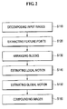
- Fig. 2 is a flow chart schematically showing the hierarchical motion estimation method of the present invention, which includes: step S110 for decomposing input images; step S120 for extracting feature points; step S 130 for arranging blocks; step S140 for estimating local motions; step S150 for estimating a global motion; and step S 160 for compounding images.
- the image decomposition unit 410 decomposes first and second input images occurring sequentially in time into at least two hierarchical, multi-resolution images.
- the first and second input images correspond to previous and current images, respectively.
- Fig. 3A shows a multi-resolution image pyramid represented by Eq. (1).
- the image of 2 n x2 n resolution at the bottom of the pyramid is an original image decomposed into hierarchical, multi-resolution images in the bottom-up manner.
- 3B shows a mapping process, wherein pixel f k ( i, j ) at k level is produced from four pixels f k+ 1 (2 i, 2 j ) , f k+ 1 (2 i, 2 j+ 1) , f k+ 1 (2 i +1,2 j ) and f k+ 1 (2 i +1, 2 j+ 1) adjacent to each other at k+1 level.
- the mapping function from an upper level to a lower level is a low-pass operation, whereby high frequency components are suppressed to obtain a lower resolution image.
- the feature extraction unit 420 selects an arbitrary image among the multi-level resolution images decomposed from the second input image. It then divides the selected image into at least two motion estimation areas and extracts feature points from the motion estimation areas.
- the lowest resolution image is selected and the feature points are extracted from the motion estimation areas in the lowest resolution image. Accordingly, since a speckle noise is reduced in the input image, the feature points can be more accurately extracted while the calculation time is reduced.
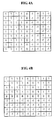
- the x-axial and y-axial gradient magnitude I x and I y at each pixel are calculated by using 9x9 kernel matrices, i.e., x-axial and y-axial edge operators, respectively (shown in Figs. 4A and 4B). Then, the corner where both the x-axial and y-axial gradient magnitudes (edge strengths) have large values is extracted as a feature point in each motion estimation area by using Eq. (2).
- the block arrangement unit 430 arranges blocks with specified sizes to surround the extracted feature points.
- Fig. 5A shows the block arrangement in the hierarchical motion estimation method.
- blocks 530 are arranged to contain the extracted feature points 520 in the motion estimation areas 510.
- the motion estimation areas 510 are preferably separated from each other at step S120 in order to prevent the blocks from overlapping each other.
- the motion estimation unit 440 estimates local motions of the blocks by matching the second input image with the first input image. That is, the motion of blocks is estimated by estimating the positions of the previous image, which correspond to the blocks in the current image.
- SAD Sum Absolute Difference
- the search window is set to have a horizontal length longer than a longitudinal length due to a large motion in a horizontal direction in the sequence of ultrasound images.
- the search window is sufficiently large to contain motion between the ultrasound images.
- the search window can be made to be smaller without compromising accuracy while reducing the amount of calculation.
- the global motion is estimated by analyzing the local motions of the blocks.
- the image compounding unit 450 creates a panoramic image by compounding the sequential images after the global motion estimation.
- the techniques for combining the images include image growing, recursive spatial compounding, ramp compounding and the like.
- the image growing technique only puts new pixel data in a non-overlapping part to a panoramic image buffer.
- the recursive spatial compounding technique recursively averages a new image frame with the existing panoramic image.
- the ramp compounding technique provides weight ramps for both the new image frame and the existing panoramic image in an overlapping area.
- the center of rotation in the overlapping area is modified by estimating a rotation angle.
- a frame averaging method is employed to reduce the discontinuity between the new image frame and the existing panoramic image.
- Figs. 6A and 6B are ultrasound images showing skin parts to explain the image compounding step in the hierarchical motion estimation method of the present invention.
- the portions of respective images are combined without combining the entire images.
- the center of rotation is changed from the center 610 of overlapping area to a skin position 620.
- the changed center of rotation (skin position 620) is then moved by an estimated motion in the x-axial direction (B1) and moved to a skin position in the y-axial direction (B2).
- the new image frame is combined with the existing panoramic image by rotating it around the skin position (B3).
Landscapes
- Engineering & Computer Science (AREA)
- Physics & Mathematics (AREA)
- Multimedia (AREA)
- Computer Vision & Pattern Recognition (AREA)
- General Physics & Mathematics (AREA)
- Theoretical Computer Science (AREA)
- Health & Medical Sciences (AREA)
- Life Sciences & Earth Sciences (AREA)
- Biomedical Technology (AREA)
- Molecular Biology (AREA)
- Pathology (AREA)
- Radiology & Medical Imaging (AREA)
- Biophysics (AREA)
- Heart & Thoracic Surgery (AREA)
- Medical Informatics (AREA)
- Nuclear Medicine, Radiotherapy & Molecular Imaging (AREA)
- Surgery (AREA)
- Animal Behavior & Ethology (AREA)
- General Health & Medical Sciences (AREA)
- Public Health (AREA)
- Veterinary Medicine (AREA)
- Image Analysis (AREA)
- Ultra Sonic Daignosis Equipment (AREA)
- Image Processing (AREA)
Abstract
Description
- The present invention generally relates to a method of forming ultrasound images and a system using the same, and more particularly to a method of estimating hierarchical motion for accurately estimating real-time motion from a sequence of ultrasound images and an ultrasound imaging system using the same.
- Ultrasound imaging is a non-invasive technique typically used for examining internal organs. Ultrasound imaging is performed by sending ultrasound waves into the body. The reflected ultrasound waves are recorded and then displayed as a real-time visual image. Since the ultrasound images are displayed in real time, they can show the movements of internal tissues, organs and blood flow.
- The ultrasound images are used in various medical applications. Thus, wide-view images (i.e., panoramic images) need to be acquired from a sequence of ultrasound images. These panoramic images display the organs and their adjacent anatomical features in one single image, thereby eliminating the need for physicians to mentally piece together a complete picture of anatomical structures. For example, the panoramic images can display both lobes of the thyroid gland on a single image to thereby provide an accurate image representation of various thyroid disorders.
- To acquire the panoramic image, it is essential to accurately estimate motion in sequential images. The known techniques for estimating motion include the gradient technique, pel-recursive technique, block matching technique, etc. In the gradient and pel-recursive techniques, the motion is estimated for every pixel in order to obtain motion information. However, they are complicated and require an enormous amount of calculation. As such, the block matching technique is more widely used than the above techniques. In the block matching technique, the arrangement and sizes of the blocks affect the performance of motion estimation. Specifically, the arrangement of blocks affects the estimation variance of global motion components, whereas the sizes of blocks influence the amount of calculation. In the global motion estimation, it is important to regularly arrange the blocks in their respective motion estimation areas.
- However, when the panoramic ultrasound images are obtained by using the block matching technique, the amount of calculation is very large since the blocks must be enlarged to contain features. Further, a speckle noise is examined in the ultrasound images since the phase change occurs due to a medium and the like when the ultrasound waves are reflected. The speckle noise degrades the quality and interpretation of the images. Therefore, it takes a very long time to acquire the panoramic ultrasound images. Thus, it becomes very difficult to obtain accurate panoramic ultrasound images.
- The present invention provides a method of estimating hierarchical motion to accurately display a sequence of images in real time by decreasing an amount of calculation for processing sequential images as well as to reduce an error in global motion estimation. Further, the present invention provides an ultrasound imaging system that uses such hierarchical motion estimation method.
- In accordance with one aspect of the present invention, there is provided a hierarchical motion estimation method, which includes the following steps: (1) decomposing first and second input images into at least two hierarchical, multi-resolution images; (2) selecting one of the multi-resolution images decomposed from the second input image, dividing the selected image into at least two motion estimation areas and extracting feature points from the motion estimation areas; (3) arranging blocks with specified sizes to surround the extracted feature points; and (4) estimating local motions of the blocks by matching the second input image with the first input image and predicting a global motion in the motion estimation areas.
- In accordance with another aspect of the present invention, there is provided an ultrasound imaging system, which includes the following: (1) an image decomposition unit for decomposing first and second ultrasound input images into at least two hierarchical, multi-resolution images; (2) a feature extraction unit for selecting one of the multi-resolution images decomposed from the second input image, the feature extraction unit further being configured to divide the selected image into at least two motion estimation areas and extract feature points from the motion estimation areas; (3) a block arrangement unit for arranging blocks with specified sizes to surround the extracted feature points; and (4) a motion estimation unit for estimating local motions of the blocks by matching the second input image with the first input image to predict a global motion in the motion estimation areas.
- Preferably, the blocks are arranged so as to be separated from each other. Further, the input image may be decomposed into hierarchical, multi-resolution images according to the following equation:

wherein fk (i, j) represents a pixel at a position (i, j) in an image of k-level resolution, and i and j (i, j = 0, ..., 2 k -1) are coordinates of pixels. Furthermore, the feature points may be extracted from an image having the lowest resolution. The feature points may be extracted according to the following equation:
wherein
- In accordance with still another aspect of the present invention, there is provided a method for forming a panoramic image from sequential images by using hierarchical motion estimation in an ultrasound imaging system, which includes the following steps: a) decomposing each of first and second input images occurring sequentially into at least two hierarchical multi-resolution images; b) dividing a lowest resolution image of the multi-resolution images decomposed from the second input image into at least two motion estimation areas and extracting feature points from the motion estimation areas, respectively; c) arranging blocks having a specified size to surround the extracted feature points, respectively; d) setting a search window on a lowest resolution image of the multi-resolution images decomposed from the first input image; e) matching the blocks with the lowest resolution image of the first input image within the search window to estimate local motion in the blocks; f) estimating global motion in the motion estimation areas by using the estimated local motion; and h) compounding the first and second input images on the basis of the estimated global motion to form a panoramic image.
- In accordance with the present invention, since the feature points are extracted by using the multi-resolution images, the error caused by a speckle noise can be reduced and the calculation time can be decreased. Further, in accordance with the present invention, since the blocks are separately arranged after dividing into the motion estimation areas, the calculation time can be reduced without affecting accuracy.
- The above and other objects and features of the present invention will become apparent from the following descriptions of preferred embodiments given in conjunction with the accompanying drawings, in which:
- Fig. 1 is a block diagram showing the schematic configuration of an ultrasound imaging system constructed in accordance with the preferred embodiment of the present invention;
- Fig. 2 is a flow chart schematically showing a hierarchical motion estimation method in accordance with the preferred embodiment of the present invention;
- Figs. 3A and 3B show a multi-resolution image pyramid and a mapping process, respectively;
- Figs. 4A and 4B are 9x9 kernel matrices, which are x-axial and y-axial edge operators, respectively;
- Fig. 5A shows the block arrangement in the hierarchical motion estimation method in accordance with the preferred embodiment of the present invention;
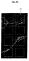
- Fig. 5B shows a modification of the block arrangement; and
- Figs. 6A and 6B are ultrasound images for explaining an image compounding step in the hierarchical motion estimation method in accordance with the preferred embodiment of the present invention.
- Hereinafter, the preferred embodiments of the present invention will be described with reference to the accompanying drawings.
- Fig. 1 is a block diagram showing the schematic configuration of an ultrasound imaging system, which is constructed in accordance with the preferred embodiment of the present invention.
- Referring to Fig. 1, an
ultrasound imaging system 400 includes: animage decomposition unit 410; afeature extraction unit 420; ablock arrangement unit 430; amotion estimation unit 440; animage compounding unit 450; and adisplay unit 460. - To estimate the motion with first and second ultrasound input images, the
image decomposition unit 410 decomposes the first and second ultrasound input images into at least two hierarchical, multi-resolution images. Thefeature extraction unit 420 selects an arbitrary image among the multi-level resolution images decomposed from the second input image. It then divides the selected image into at least two motion estimation areas and extracts feature points from the motion estimation areas. Preferably, the lowest resolution image is selected and the feature points are extracted from the motion estimation areas in the lowest resolution image. Theblock arrangement unit 430 arranges blocks with specified sizes to surround the extracted feature points. Preferably, the blocks are arranged in a way so as not to overlap each other. Themotion estimation unit 440 estimates local motions of the blocks by matching the second input image with the first input image and predicts a global motion in the motion estimation areas. Theimage compounding unit 450 creates a panoramic image by compounding the sequential images after the global motion estimation. Image compounding is performed in order to produce a seamless image by controlling the brightness information in pixels in an overlapping area of the sequential images. Thedisplay unit 460 displays a compound image transferred from a frame buffer (not shown) on a monitor (not shown). - The hierarchical motion estimation method, which is in accordance with the preferred embodiment of the present invention, will now be described below.
- Fig. 2 is a flow chart schematically showing the hierarchical motion estimation method of the present invention, which includes: step S110 for decomposing input images; step S120 for extracting feature points;
step S 130 for arranging blocks; step S140 for estimating local motions; step S150 for estimating a global motion; and step S 160 for compounding images. - At step S110, the
image decomposition unit 410 decomposes first and second input images occurring sequentially in time into at least two hierarchical, multi-resolution images. The first and second input images correspond to previous and current images, respectively. - The input image is decomposed into hierarchical, multi-resolution images according to the following equation:

wherein f k(i, j) represents a pixel at a position (i, j) in an image of k-level resolution, and i and j (i, j = 0, ..., 2 k -1) are coordinates of pixels. - Fig. 3A shows a multi-resolution image pyramid represented by Eq. (1). The multi-resolution image pyramid includes a series of images having 2kx2k resolution (k = 0, ..., n-1). The image of 2nx2n resolution at the bottom of the pyramid is an original image decomposed into hierarchical, multi-resolution images in the bottom-up manner. Fig. 3B shows a mapping process, wherein pixel fk (i, j) at k level is produced from four pixels f k+1(2i,2j), f k+1(2i,2j+1), f k+1(2i+1,2j) and f k+1(2i+1, 2j+1) adjacent to each other at k+1 level. At this time, the mapping function from an upper level to a lower level is a low-pass operation, whereby high frequency components are suppressed to obtain a lower resolution image.
- At step S120, the
feature extraction unit 420 selects an arbitrary image among the multi-level resolution images decomposed from the second input image. It then divides the selected image into at least two motion estimation areas and extracts feature points from the motion estimation areas. - Preferably, the lowest resolution image is selected and the feature points are extracted from the motion estimation areas in the lowest resolution image. Accordingly, since a speckle noise is reduced in the input image, the feature points can be more accurately extracted while the calculation time is reduced.
- The feature points are extracted from the motion estimation areas by using the Harris-Stephen corner detection method, which is represented by the following equation:

wherein
- In each motion estimation area, the x-axial and y-axial gradient magnitude Ix and Iy at each pixel are calculated by using 9x9 kernel matrices, i.e., x-axial and y-axial edge operators, respectively (shown in Figs. 4A and 4B). Then, the corner where both the x-axial and y-axial gradient magnitudes (edge strengths) have large values is extracted as a feature point in each motion estimation area by using Eq. (2). At step S130, the
block arrangement unit 430 arranges blocks with specified sizes to surround the extracted feature points. - Fig. 5A shows the block arrangement in the hierarchical motion estimation method. Referring to Fig. 5A, blocks 530 are arranged to contain the extracted
feature points 520 in themotion estimation areas 510. At this time, when the feature points are close to each other, there may be an error in the global motion estimation due to the blocks overlapping each other. Thus, as shown in Fig. 5B, themotion estimation areas 510 are preferably separated from each other at step S120 in order to prevent the blocks from overlapping each other. - At step S140, the
motion estimation unit 440 estimates local motions of the blocks by matching the second input image with the first input image. That is, the motion of blocks is estimated by estimating the positions of the previous image, which correspond to the blocks in the current image. - For the local motion estimation, block matching is performed to find a reference block with the best match compared to the block in the current image. The Sum Absolute Difference (SAD), which is the sum of absolute differences between the values of corresponding pixels between each block in the current image and a reference block, is investigated within a search window in the previous image. The best match is considered to occur when the SAD value is at a minimum.
- Generally, the search window is set to have a horizontal length longer than a longitudinal length due to a large motion in a horizontal direction in the sequence of ultrasound images. The search window is sufficiently large to contain motion between the ultrasound images. However, it should be noted that the larger the search window gets, the larger the amount of calculation becomes.
- In this embodiment, by using the above-described lowest resolution image, the search window can be made to be smaller without compromising accuracy while reducing the amount of calculation.
- At
step S 150, the global motion is estimated by analyzing the local motions of the blocks. At step S160, theimage compounding unit 450 creates a panoramic image by compounding the sequential images after the global motion estimation. - The techniques for combining the images include image growing, recursive spatial compounding, ramp compounding and the like. The image growing technique only puts new pixel data in a non-overlapping part to a panoramic image buffer. The recursive spatial compounding technique recursively averages a new image frame with the existing panoramic image. The ramp compounding technique provides weight ramps for both the new image frame and the existing panoramic image in an overlapping area.
- In case of image growing technique, the continuity of the compound image can be enhanced by averaging the frames in the overlapping area through the following equation:

wherein G and I represent a panoramic image and an ultrasound image, respectively; x and y are coordinatcs: and t is a frame number. - In this embodiment, the center of rotation in the overlapping area is modified by estimating a rotation angle. Further, a frame averaging method is employed to reduce the discontinuity between the new image frame and the existing panoramic image.
- Figs. 6A and 6B are ultrasound images showing skin parts to explain the image compounding step in the hierarchical motion estimation method of the present invention.
- In the image compounding step, the portions of respective images are combined without combining the entire images. As shown in Fig. 6A, the center of rotation is changed from the
center 610 of overlapping area to askin position 620. As shown in Fig. 6B, the changed center of rotation (skin position 620) is then moved by an estimated motion in the x-axial direction (B1) and moved to a skin position in the y-axial direction (B2). Finally, the new image frame is combined with the existing panoramic image by rotating it around the skin position (B3). - While the present invention has been described and illustrated with respect to a preferred embodiment of the invention, it will be apparent to those skilled in the art that variations and modifications are possible without deviating from the broad principles and teachings of the present invention, which should be limited solely by the scope of the claims appended hereto.
Claims (10)
- A method of estimating a hierarchical motion, comprising:decomposing a first input image and a second input image into at least two hierarchical, multi-resolution images;selecting one of the multi-resolution images decomposed from the second input image, dividing the selected image into at least two motion estimation areas and extracting feature points from the motion estimation areas;arranging blocks with specified sizes to surround the extracted feature points; andestimating a local motion of the blocks by matching the second input image with the first input image and a global motion in the motion estimation areas.
- The method of Claim 1, wherein the blocks are arranged in a manner so as to be separated from each other.
- The method of Claim 1, wherein the input image is decomposed into hierarchical, multi-resolution images according to the following equation:

wherein fk (i,j) represents a pixel at a position (i,j) in an image of k-level resolution, and i and j (i, j = 0, ..., 2 k -1) are coordinates of pixels. - The method of Claim 1, wherein the feature points are extracted from an image with a lowest resolution.
- The method of Claim 1, wherein the feature points are extracted according to the following equation:


- The method of Claim 1, wherein the input image is an ultrasound image.
- The method of Claim 1. wherein the first and second input images are sequential in time.
- An ultrasound imaging system, comprising:an image decomposition unit for decomposing first and second ultrasound input images into at least two hierarchical, multi-resolution images;a feature extraction unit for selecting one of the multi-resolution images decomposed from the second input image, the feature extraction unit being configured to divide the selected image into at least two motion estimation areas and extract feature points from the motion estimation areas;a block arrangement unit for arranging blocks with specified sizes to surround the extracted feature points; anda motion estimation unit for estimating a local motion of the blocks by matching the second input image with the first input image and a global motion in the motion estimation areas.
- The system of Claim 8, wherein the blocks are arranged in a manner so as to be separated from each other.
- A method for forming a panoramic image from sequential images by using hierarchical motion estimation in an ultrasound imaging system, comprising:decomposing each of first and second input images occurring sequentially into at least two hierarchical multi-resolution images;dividing a lowest resolution image of the multi-resolution images decomposed from the second input image into at least two motion estimation areas and extracting feature points from the motion estimation areas, respectively;arranging blocks having a specified size to surround the extracted feature points, respectively;setting a search window on a lowest resolution image of the multi-resolution images decomposed from the first input image;matching the blocks with the lowest resolution image of the first input image within the search window to estimate local motion in the blocks;estimating global motion in the motion estimation areas by using the estimated local motion; andcompounding the first and second input images on the basis of the estimated global motion to form a panoramic image.
Applications Claiming Priority (1)
| Application Number | Priority Date | Filing Date | Title |
|---|---|---|---|
| KR1020050058972A KR100869497B1 (en) | 2005-07-01 | 2005-07-01 | Hierarchical Motion Estimation Method and Ultrasonic Imaging Applied to It |
Publications (1)
| Publication Number | Publication Date |
|---|---|
| EP1739623A1 true EP1739623A1 (en) | 2007-01-03 |
Family
ID=37012055
Family Applications (1)
| Application Number | Title | Priority Date | Filing Date |
|---|---|---|---|
| EP06013450A Withdrawn EP1739623A1 (en) | 2005-07-01 | 2006-06-29 | Hierarchical motion estimation method and ultrasound imaging system using the same |
Country Status (4)
| Country | Link |
|---|---|
| US (1) | US20070036408A1 (en) |
| EP (1) | EP1739623A1 (en) |
| JP (1) | JP2007007426A (en) |
| KR (1) | KR100869497B1 (en) |
Cited By (2)
| Publication number | Priority date | Publication date | Assignee | Title |
|---|---|---|---|---|
| CN101396287B (en) * | 2007-09-28 | 2012-02-08 | 株式会社东芝 | Ultrasound diagnosis apparatus and ultrasound diagnosis image generation method |
| CN101711686B (en) * | 2008-10-07 | 2013-04-24 | 深圳迈瑞生物医疗电子股份有限公司 | Imaging method and imaging system for real-time space compound and ultrasonic imaging system thereof |
Families Citing this family (15)
| Publication number | Priority date | Publication date | Assignee | Title |
|---|---|---|---|---|
| JP5139716B2 (en) * | 2007-05-16 | 2013-02-06 | キヤノン株式会社 | Image search apparatus and image search method |
| KR100946710B1 (en) * | 2007-10-24 | 2010-03-12 | 주식회사 메디슨 | Ultrasound Image Processing System and Method |
| JP4497216B2 (en) * | 2008-03-03 | 2010-07-07 | ソニー株式会社 | Image processing apparatus, image processing method, and computer program |
| KR20100000671A (en) * | 2008-06-25 | 2010-01-06 | 삼성전자주식회사 | Method for image processing |
| KR20100026334A (en) * | 2008-08-29 | 2010-03-10 | 김진우 | System for flight and method of control therefor |
| US9058063B2 (en) | 2009-05-30 | 2015-06-16 | Sony Computer Entertainment Inc. | Tracking system calibration using object position and orientation |
| KR101268520B1 (en) * | 2009-12-14 | 2013-06-04 | 한국전자통신연구원 | The apparatus and method for recognizing image |
| KR101140934B1 (en) * | 2010-08-05 | 2012-05-03 | 삼성전기주식회사 | Method for Estimating Acoustic Velocity of Ultrasonic Image and Ultrasonic Diagnosis Apparatus using the same |
| KR101232021B1 (en) * | 2010-11-29 | 2013-02-08 | 삼성메디슨 주식회사 | Ultrasound system and method for processing frame average based on motion estimation |
| TWI506595B (en) | 2011-01-11 | 2015-11-01 | Altek Corp | Method and apparatus for generating panorama |
| KR101880634B1 (en) | 2011-08-09 | 2018-08-16 | 삼성전자주식회사 | Method and apparatus for generating 3d volume panorama |
| TWI446897B (en) * | 2011-08-19 | 2014-08-01 | Ind Tech Res Inst | Ultrasound image registration apparatus and method thereof |
| US9305362B1 (en) * | 2014-02-28 | 2016-04-05 | Xilinx, Inc. | Image stabilization |
| KR101550665B1 (en) | 2014-03-27 | 2015-09-07 | 서강대학교산학협력단 | Methods and Systems of Optimized Hierarchical Block Matching, Methods of Image Registration and Video Compression Based on Optimized Hierarchical Block Matching |
| CN105872310B (en) * | 2016-04-20 | 2020-03-17 | 上海联影医疗科技有限公司 | Image motion detection method and image noise reduction method for movable imaging equipment |
Citations (2)
| Publication number | Priority date | Publication date | Assignee | Title |
|---|---|---|---|---|
| US5782766A (en) * | 1995-03-31 | 1998-07-21 | Siemens Medical Systems, Inc. | Method and apparatus for generating and displaying panoramic ultrasound images |
| US6456731B1 (en) * | 1998-05-21 | 2002-09-24 | Sanyo Electric Co., Ltd. | Optical flow estimation method and image synthesis method |
Family Cites Families (18)
| Publication number | Priority date | Publication date | Assignee | Title |
|---|---|---|---|---|
| KR960028481A (en) * | 1994-12-29 | 1996-07-22 | 배순훈 | Motion estimation device |
| BR9607845A (en) * | 1995-03-22 | 1999-11-30 | Idt Deutschland Gmbh | Method and apparatus for coordinating movement determination across multiple frames. |
| US5575286A (en) * | 1995-03-31 | 1996-11-19 | Siemens Medical Systems, Inc. | Method and apparatus for generating large compound ultrasound image |
| JP3406785B2 (en) * | 1996-09-26 | 2003-05-12 | 株式会社東芝 | Cardiac function analysis support device |
| US6285711B1 (en) * | 1998-05-20 | 2001-09-04 | Sharp Laboratories Of America, Inc. | Block matching-based method for estimating motion fields and global affine motion parameters in digital video sequences |
| KR20010024416A (en) * | 1998-08-05 | 2001-03-26 | 요트.게.아. 롤페즈 | Static image generation method and device |
| US6210328B1 (en) * | 1998-10-01 | 2001-04-03 | Atl Ultrasound | Ultrasonic diagnostic imaging system with variable spatial compounding |
| US6159152A (en) * | 1998-10-26 | 2000-12-12 | Acuson Corporation | Medical diagnostic ultrasound system and method for multiple image registration |
| JP3469122B2 (en) * | 1999-03-10 | 2003-11-25 | 日本電信電話株式会社 | Video segment classification method and apparatus for editing, and recording medium recording this method |
| US6238345B1 (en) * | 1999-06-30 | 2001-05-29 | Atl Ultrasound | Image memory for extended field of view ultrasonic diagnostic imaging |
| US6442289B1 (en) * | 1999-06-30 | 2002-08-27 | Koninklijke Philips Electronics N.V. | Extended field of view ultrasonic diagnostic imaging |
| AU1412100A (en) * | 1999-11-29 | 2001-06-12 | Sony Corporation | Video/audio signal processing method and video/audio signal processing apparatus |
| US6416477B1 (en) * | 2000-08-22 | 2002-07-09 | Koninklijke Philips Electronics N.V. | Ultrasonic diagnostic systems with spatial compounded panoramic imaging |
| JP2002230572A (en) * | 2000-11-28 | 2002-08-16 | Monolith Co Ltd | Method and device for image effect, method and device for image interpolation |
| JP4157686B2 (en) * | 2001-05-15 | 2008-10-01 | 株式会社モノリス | Method and apparatus for image encoding and decoding |
| JP4704630B2 (en) * | 2001-09-14 | 2011-06-15 | アロカ株式会社 | Ultrasonic panoramic image forming device |
| CN101036150B (en) * | 2004-07-30 | 2010-06-09 | 欧几里得发现有限责任公司 | Apparatus and method for processing video data |
| US7373012B2 (en) * | 2005-02-01 | 2008-05-13 | Mitsubishi Electric Research Laboratories, Inc. | Detecting moving objects in videos with corner-based background model |
-
2005
- 2005-07-01 KR KR1020050058972A patent/KR100869497B1/en not_active Expired - Lifetime
-
2006
- 2006-06-29 EP EP06013450A patent/EP1739623A1/en not_active Withdrawn
- 2006-06-30 US US11/477,653 patent/US20070036408A1/en not_active Abandoned
- 2006-06-30 JP JP2006182400A patent/JP2007007426A/en active Pending
Patent Citations (2)
| Publication number | Priority date | Publication date | Assignee | Title |
|---|---|---|---|---|
| US5782766A (en) * | 1995-03-31 | 1998-07-21 | Siemens Medical Systems, Inc. | Method and apparatus for generating and displaying panoramic ultrasound images |
| US6456731B1 (en) * | 1998-05-21 | 2002-09-24 | Sanyo Electric Co., Ltd. | Optical flow estimation method and image synthesis method |
Non-Patent Citations (2)
| Title |
|---|
| KELLER Y ET AL: "FAST GRADIENT METHODS BASED ON GLOBAL MOTION ESTIMATION FOR VIDEO COMPRESSION", IEEE TRANSACTIONS ON CIRCUITS AND SYSTEMS FOR VIDEO TECHNOLOGY, IEEE SERVICE CENTER, PISCATAWAY, NJ, US, vol. 13, no. 4, April 2003 (2003-04-01), pages 300 - 309, XP001158239, ISSN: 1051-8215 * |
| ZHANG Z ET AL: "A ROBUST TECHNIQUE FOR MATCHING TWO UNCALIBRATED IMAGES THROUGH THE RECOVERY OF THE UNKNOWN EPIPOLAR GEOMETRY", ARTIFICIAL INTELLIGENCE, ELSEVIER SCIENCE PUBLISHER B.V., AMSTERDAM, NL, vol. 78, no. 1/2, 1995, pages 87 - 119, XP001148319, ISSN: 0004-3702 * |
Cited By (3)
| Publication number | Priority date | Publication date | Assignee | Title |
|---|---|---|---|---|
| CN101396287B (en) * | 2007-09-28 | 2012-02-08 | 株式会社东芝 | Ultrasound diagnosis apparatus and ultrasound diagnosis image generation method |
| US8647275B2 (en) | 2007-09-28 | 2014-02-11 | Kabushiki Kaisha Toshiba | Ultrasound diagnosis apparatus and program |
| CN101711686B (en) * | 2008-10-07 | 2013-04-24 | 深圳迈瑞生物医疗电子股份有限公司 | Imaging method and imaging system for real-time space compound and ultrasonic imaging system thereof |
Also Published As
| Publication number | Publication date |
|---|---|
| KR20070003206A (en) | 2007-01-05 |
| JP2007007426A (en) | 2007-01-18 |
| KR100869497B1 (en) | 2008-11-21 |
| US20070036408A1 (en) | 2007-02-15 |
Similar Documents
| Publication | Publication Date | Title |
|---|---|---|
| US20070036408A1 (en) | Hierarchical motion estimation method and ultrasound imaging system using the same | |
| EP1074001B1 (en) | Image processing method, system and apparatus for forming an overview image of an elongated scene | |
| US5359513A (en) | Method and system for detection of interval change in temporally sequential chest images | |
| Bankman | Handbook of medical imaging: processing and analysis management | |
| US8842936B2 (en) | Method, apparatus, and program for aligning images | |
| Wen et al. | An accurate and effective FMM-based approach for freehand 3D ultrasound reconstruction | |
| EP2100275B1 (en) | Comparison workflow automation by registration | |
| US7324660B2 (en) | Image position matching apparatus and image processing apparatus | |
| US20070133736A1 (en) | Devices, systems, and methods for imaging | |
| US8682051B2 (en) | Smoothing of dynamic data sets | |
| US8494239B2 (en) | Image processing device, method and program | |
| US8111947B2 (en) | Image processing apparatus and method which match two images based on a shift vector | |
| JP2012523889A (en) | Overlapping, subtraction and display of chest radiographs | |
| US7062078B2 (en) | Method and device for the registration of images | |
| Deliyski | Endoscope motion compensation for laryngeal high-speed videoendoscopy | |
| WO2009145076A1 (en) | Image processing device, image processing method, and image processing program | |
| JPH09138853A (en) | Image data processing method and image data processing device | |
| Sawant et al. | Ultrasound image enhancement using super resolution | |
| US8634630B2 (en) | Method and apparatus for enhancing representations of micro-calcifications in a digital mammogram image | |
| US20050078882A1 (en) | Pixelation reconstruction for image resolution and image data transmission | |
| KR100450278B1 (en) | A medical image processing system and the method thereof | |
| US20080144904A1 (en) | Apparatus and Method for the Processing of Sectional Images | |
| US5530789A (en) | Image processing apparatus and method for constructing a functional image using feature amounts of functions approximating changes in image data on a time axis | |
| Wang et al. | Gan-based architecture for low-dose computed tomography imaging denoising | |
| US20080137928A1 (en) | Method and System for Registering CT Data Sets |
Legal Events
| Date | Code | Title | Description |
|---|---|---|---|
| PUAI | Public reference made under article 153(3) epc to a published international application that has entered the european phase |
Free format text: ORIGINAL CODE: 0009012 |
|
| AK | Designated contracting states |
Kind code of ref document: A1 Designated state(s): AT BE BG CH CY CZ DE DK EE ES FI FR GB GR HU IE IS IT LI LT LU LV MC NL PL PT RO SE SI SK TR |
|
| AX | Request for extension of the european patent |
Extension state: AL BA HR MK YU |
|
| 17P | Request for examination filed |
Effective date: 20070524 |
|
| 17Q | First examination report despatched |
Effective date: 20070621 |
|
| AKX | Designation fees paid |
Designated state(s): DE FR IT |
|
| STAA | Information on the status of an ep patent application or granted ep patent |
Free format text: STATUS: THE APPLICATION HAS BEEN WITHDRAWN |
|
| 18W | Application withdrawn |
Effective date: 20090216 |