EP1739515A1 - Kanban control cycle system - Google Patents
Kanban control cycle system Download PDFInfo
- Publication number
- EP1739515A1 EP1739515A1 EP05014308A EP05014308A EP1739515A1 EP 1739515 A1 EP1739515 A1 EP 1739515A1 EP 05014308 A EP05014308 A EP 05014308A EP 05014308 A EP05014308 A EP 05014308A EP 1739515 A1 EP1739515 A1 EP 1739515A1
- Authority
- EP
- European Patent Office
- Prior art keywords
- state
- control cycle
- control
- cycles
- states
- Prior art date
- Legal status (The legal status is an assumption and is not a legal conclusion. Google has not performed a legal analysis and makes no representation as to the accuracy of the status listed.)
- Granted
Links
Images



Classifications
-
- G—PHYSICS
- G05—CONTROLLING; REGULATING
- G05B—CONTROL OR REGULATING SYSTEMS IN GENERAL; FUNCTIONAL ELEMENTS OF SUCH SYSTEMS; MONITORING OR TESTING ARRANGEMENTS FOR SUCH SYSTEMS OR ELEMENTS
- G05B19/00—Program-control systems
- G05B19/02—Program-control systems electric
- G05B19/418—Total factory control, i.e. centrally controlling a plurality of machines, e.g. direct or distributed numerical control [DNC], flexible manufacturing systems [FMS], integrated manufacturing systems [IMS] or computer integrated manufacturing [CIM]
- G05B19/41865—Total factory control, i.e. centrally controlling a plurality of machines, e.g. direct or distributed numerical control [DNC], flexible manufacturing systems [FMS], integrated manufacturing systems [IMS] or computer integrated manufacturing [CIM] characterised by job scheduling, process planning, material flow
-
- G—PHYSICS
- G06—COMPUTING OR CALCULATING; COUNTING
- G06Q—INFORMATION AND COMMUNICATION TECHNOLOGY [ICT] SPECIALLY ADAPTED FOR ADMINISTRATIVE, COMMERCIAL, FINANCIAL, MANAGERIAL OR SUPERVISORY PURPOSES; SYSTEMS OR METHODS SPECIALLY ADAPTED FOR ADMINISTRATIVE, COMMERCIAL, FINANCIAL, MANAGERIAL OR SUPERVISORY PURPOSES, NOT OTHERWISE PROVIDED FOR
- G06Q10/00—Administration; Management
- G06Q10/06—Resources, workflows, human or project management; Enterprise or organisation planning; Enterprise or organisation modelling
-
- G—PHYSICS
- G06—COMPUTING OR CALCULATING; COUNTING
- G06Q—INFORMATION AND COMMUNICATION TECHNOLOGY [ICT] SPECIALLY ADAPTED FOR ADMINISTRATIVE, COMMERCIAL, FINANCIAL, MANAGERIAL OR SUPERVISORY PURPOSES; SYSTEMS OR METHODS SPECIALLY ADAPTED FOR ADMINISTRATIVE, COMMERCIAL, FINANCIAL, MANAGERIAL OR SUPERVISORY PURPOSES, NOT OTHERWISE PROVIDED FOR
- G06Q10/00—Administration; Management
- G06Q10/06—Resources, workflows, human or project management; Enterprise or organisation planning; Enterprise or organisation modelling
- G06Q10/063—Operations research, analysis or management
- G06Q10/0631—Resource planning, allocation, distributing or scheduling for enterprises or organisations
- G06Q10/06315—Needs-based resource requirements planning or analysis
-
- G—PHYSICS
- G05—CONTROLLING; REGULATING
- G05B—CONTROL OR REGULATING SYSTEMS IN GENERAL; FUNCTIONAL ELEMENTS OF SUCH SYSTEMS; MONITORING OR TESTING ARRANGEMENTS FOR SUCH SYSTEMS OR ELEMENTS
- G05B2219/00—Program-control systems
- G05B2219/30—Nc systems
- G05B2219/31—From computer integrated manufacturing till monitoring
- G05B2219/31388—Just in time JIT, kanban is box to control flow of workpiece
-
- Y—GENERAL TAGGING OF NEW TECHNOLOGICAL DEVELOPMENTS; GENERAL TAGGING OF CROSS-SECTIONAL TECHNOLOGIES SPANNING OVER SEVERAL SECTIONS OF THE IPC; TECHNICAL SUBJECTS COVERED BY FORMER USPC CROSS-REFERENCE ART COLLECTIONS [XRACs] AND DIGESTS
- Y02—TECHNOLOGIES OR APPLICATIONS FOR MITIGATION OR ADAPTATION AGAINST CLIMATE CHANGE
- Y02P—CLIMATE CHANGE MITIGATION TECHNOLOGIES IN THE PRODUCTION OR PROCESSING OF GOODS
- Y02P90/00—Enabling technologies with a potential contribution to greenhouse gas [GHG] emissions mitigation
- Y02P90/02—Total factory control, e.g. smart factories, flexible manufacturing systems [FMS] or integrated manufacturing systems [IMS]
Definitions
- This patent application relates generally to Kanban control cycles and, more particularly, a system that uses Kanban control cycles to replenish items.
- Kanban is a Japanese term that means signal.
- Kanban is one of the primary tools of a just-in-time manufacturing system (meaning a planning system for manufacturing processes that optimizes availability of material inventories at a manufacturing site to only what, when and how much is necessary).
- Kanban signals a replenishment process for production and materials, and maintains a generally orderly and efficient flow of materials throughout a manufacturing process.
- Kanban may be implemented via a printed card that contains specific information such as item name, description, quantity, etc.
- Kanban control cycles define a replenishment process in terms of operational states.
- a Kanban control cycle can be characterized as a sequence of different operational states.
- Kanban control cycles occur between a supplier and a consumer, i.e., the one replenishing an item and the one requesting that the item be replenished, respectively.
- the item can be any kind of material, such as a component or an assembly, that needs to be replenished.
- a signal indicating that the material needs to be replenished is sent from the customer to the supplier. This signal, called the Kanban, may be part of an electronic message or an actual physical device, such as a card.
- the operational state of the Kanban may be modified to provide item-related information, as described below.
- a material may be needed by a consumer for use in a machine or process.
- an operational state of the Kanban is set from “full” to "empty”.
- the consumer therefore sends a Kanban to a supplier instructing the supplier to provide more of (e.g., a specified amount of) the material.
- the Kanban identifies the material, the amount of the material, and the consumer.
- the supplier processes the order and sends the material to the consumer.
- the state of the Kanban is then changed from "empty" to "full”.
- States of a Kanban correspond to states of a cycle that is performed to replenish an item.
- Electronic Kanban systems associate a state change of a Kanban with related electronically-controlled actions, such as printing Kanban cards, visualizing replenishing scenarios, creating and sending replenishment orders (e.g. electronically transmitting a purchase order to a supplier), and updating inventory levels.
- Kanban control cycles operate on an item-by-item basis, making it difficult to address more than one item at a time. This can be problematic, particularly in situations, such as supply chains, where the supply of one item depends on the supply of another item.
- This patent application describes methods and apparatus, including computer program products, for using a Kanban control cycle to monitor a production system.
- the invention application is directed to modeling a process chain, and includes mapping processes in the process chain to control cycles, defining states for the control cycles, and defining couplings between states in different control cycles such that a state change in one control cycle causes a state change in another control cycle.
- the foregoing aspect may include designating one of the control cycles to be a leading control cycle, designating one of the control cycles to be a dependent control cycle, and defining a coupling between the leading control cycle and the dependent control cycle such that a state change in the dependent control cycles is caused by a state change in the leading control cycle.
- the control cycles may be defined in a software system for supporting material flow in the process chain.
- the control cycles may be Kanban control cycles.
- the couplings between states may be defined using a matrix that indicates an effect of a state in one control cycle on a state in another control cycle.
- a consistency rule may be defined.
- the consistency rule may ensure correct relationships between states in at least one of the dependent control cycle and the independent control cycle.
- An error state may be defined in at least one of the control cycles.
- An error state of a first control cycle may be linked with an error state of a second control cycle.
- At least one of the states may be defined in at least one Kanban card.
- the state sequence may be defined by at least one set of states of different control cycles having at least one state coupling type.
- the method for modelling process chains using control cycles comprises mapping process chains of two items into corresponding control cycles, defining for each control cycle at least two states, defining for each control cycle a state sequence, defining a state sequence coupling between states in the different control cycles such that a state change within one of the control cycles can cause a state change within the other control cycle.
- Embodiments provide establishing one control cycle as leading control cycle, establishing at least one other control cycle as dependent control cycle, defining a state sequence coupling between the one leading control cycle and the at least one dependent control cycle such that any state change within one of the dependent control cycles is caused by at least one state change within the leading control cycle.
- the state sequence coupling can be a matrix defining which state of a first control cycle causes which state of at least a second control cycle. Defining consistency rules is also possible, the consistency rules defining that state changes in the dependent control cycle caused by the state sequence coupling match with state changes of the dependent control cycle defined within the state sequence of the dependent control cycle. Defining within the state sequence coupling at least one dependent control cycle is possible.
- Embodiments also provide defining the state sequence comprises defining at least one set of states of different control cycles with a state coupling type. Embodiments further provide defining within the state coupling type, whether the coupling is bidirectional or unidirectional. Embodiments provide defining within the state coupling type, whether the state in one control cycle can be changed without being triggered by a coupled state in the other control cycle. The features of the method can be implemented within a computer program as well.
- Kanban control cycles provide a method to monitor, control, support, and automate production and supply chain management for items, based on the physical inventory of items during manufacturing. Items that are necessary during production may be readily available in small quantities. Replenishment of such items can be initiated via a Kanban control cycle by issuing a Kanban control card (referred to herein as "the Kanban").
- the Kanban describe the items to be supplied, the quantity of the items, and the customer, meaning to whom the items are to be delivered.
- the application describes a system, in particular software, for use in controlling replenishment processes for related items using Kanban control cycles.
- the software described herein maps a replenishment process of each item into a corresponding control cycle, defines at least two operational states (or simply, "states") for each cycle, defines a state sequence for each control cycle, and defines a state sequence coupling between control cycles such that a change in state of a replenishment process of one item triggers a corresponding change of state of a replenishment process of a related item.
- Such changes of state can include, but are not limited to, printing Kanbans, updating monitoring displays, and creating or updating procurement orders, inventory levels, etc.
- a process called “rigid coupling” may be used to effect state sequence coupling in Kanban control cycles.
- one control cycle is designated the “leading control cycle”
- at least one other control cycle is designated the “dependent control cycle”.
- State sequences coupling are coupled in that any state within one of the dependent control cycle is caused by at least one state in the leading control cycle.
- a state sequence coupling which constitutes a collection of state sets.
- Each state set includes a state in a state sequence of CC1, a state in a state sequence of CC,2, and a "state coupling type".
- the state coupling type controls whether the coupling between two cycles is bidirectional (change of state in CC1 triggers a change of state in CC2, and vice versa) or one-directional, and whether a change in state of one control cycle, e.g., CC2, must be being triggered by another control cycle, e.g., CC1.
- Fig. 1 illustrates a supply chain 100 for items 112.
- Fig. 1 shows a consumer 104 that requires items 112, and a supplier 102 that provides item 112. Items 112 are transported between supplier 102 and consumer 104 in containers 106.
- Items 112 are used in a production line 110. Several items 112a, 112b can be kept in stock. Each item 112c used in production line 110 is scanned by a barcode scanner 108. By scanning items 112 when used, stock of items 112 is monitored electronically.
- the supply chain of items 112 shown in Fig. 1 is controlled by an event-controlled Kanban control cycle.
- replenishment of items 112 can be correlated to item requirements.
- items 112 can be made available only when items 112 are needed, e.g., stock of an item is below a minimum level.
- a request for an item can be triggered by an event, such as scanning a last item 112 in stock.
- the control cycle state may be set to "empty”.
- a Kanban 116 e.g., a card
- the supplier 102 receives the Kanban and extracts replenishment information concerning item 112 from Kanban 116.
- the replenishment information can be obtained by scanning a barcode on the Kanban.
- the barcode is linked to master data the customer's database.
- the master data can contain, e.g., information pertaining to (e.g., identifying) the item and replenishment requirements pertaining to the item.
- items 112 are sent in containers 106 from supplier 102 to consumer 104.
- the consumer 104 can process the items automatically, e.g., scanning a barcode on the each container 106. Information from the barcode can be used by a computer system (not shown) at the consumer to update the database, and thereby keep track of items 112. The state of the control cycle for item 112 can then be set to "full”. Kanban 116 can then be deactivated/deleted/destroyed.
- Kanban control cycles manufacturing processes can be controlled and automated, thereby reducing manual intervention in the process.
- a computer system may be used to provide Kanban control cycles for items that are coupled to each other. What is meant by coupling here is that a state of a first control cycle can cause, or can be caused by, a state of a second control cycle.
- Coupling of a plurality of control cycles extends automatic replenishment to plural items, as illustrated below.
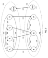
- Fig. 2 shows state sequence charts for a leading control cycle 200 and a dependent control cycle 202.
- Leading control cycle 200 is defined by four different states: A, B, C and D. State changes are defined by state transitions 204 to 216. For example, a state change from A to B is defined by transition 204. A state change from C to A is defined by transition 214.
- Dependent control cycle 202 has three states: F, G and H. State changes are defined by state transitions 220 to 228. State changes in dependent control cycle 202 are triggered (in this example, exclusively) by a coupling 240 to 248.
- the coupling between leading control cycle 200 and dependent control cycle 202 is a rigid coupling (as defined above).
- Dependent control cycle 202 is not able to change its states F, G, H until a new state in leading control cycle 200 is achieved.
- the supply chain containing the leading and dependent control cycles can include items that are always used in combination.
- the state coupling can be stored a state coupling type.
- a garage may need to be supplied regularly with spare motors and parts from a central storage facility.
- spare motors and parts can be transported in a single container, and constitute items of a Kaban control cycle.
- replenishment of each item can be controlled separately.
- each Kanban control cycle is triggered individually, i.e., a Kanban is generated for each item. This can be problematic because it requires manual intervention, which can be error prone.
- Coupling control cycles 200 and 202 can reduce the amount of manual interaction required to replenish the items. For example, each time spare motors need to be replenished, corresponding replacement parts therefor can also be ordered.
- a Kanban "impulse" can constitute scanning of an order code. This impulse can trigger leading control cycle 200 to change its state from D “full” to B “empty”. The dependent control cycle thereby is triggered to also change its state from H “full” to F “empty”.
- Two Kanban cards are generated by the consumer and provided to the supplier.
- the supplier can produce the items and send them back to the consumer in one container.
- the container can be scanned, e.g., by a barcode scanner.
- the state of the leading control cycle 200 can be set to D, "full”.
- the state of dependent control cycle 202 is also set to H "full”.
- Leading control cycle 200 and dependent control cycle 202, and the coupling between them, can be customized once in order to automate combined processing in any manner desired.
- State changes of control cycles can be subject to certain restrictions. While customizing the control cycles, the state sequences can be defined. Exemplary states of control cycle 202 may be “wait” (A), “empty” (B), “in process” (C), and “full” (D). Additional states can be “in transit” or “in use”, each describing a temporal state of an item. “Wait” can indicate that the material is used up, but that replenishment is not yet required. "In process” can indicate that the requested item is currently in production. “In transit” can indicate that an item is on its way from the supplier to the consumer. “In use” can indicate that the item is currently being used by the consumer.
- An error state "error” 230, 232 which indicates a process error, can be used in each control cycle 200, 202.
- "error” can indicate that a desired state could not be set successfully in a control cycle.
- control cycles 200, 202 are coupled, an error state in one of control cycles 200, 202 causes an error state in the other control cycle 200, 202. Errors typically need to be resolved manually.
- Fig. 3 illustrates a state sequence matrix defining state changes of leading control cycle 200.
- the columns indicate states and the rows indicate state transitions.
- “S” indicates the start state of a state change and "E” indicates the end state of the state change.
- the state change from “A” to “B” is represented by state transition 204; the change from “A” to “C” is represented by state transition 210; and the change from "C” to “A” is represented by state transition 214.
- the matrix facilitates customization of state changes between states “A” to "D” in leading control cycle 200.
- Fig. 4 illustrates a state sequence matrix defining state changes for dependent control cycle 202.
- columns indicate states and rows indicate state transitions.
- "S” indicates a start state of a state change and "E” indicates the end state of a state change.
- state transition 220 the state change from “F” to "G” is represented by state transition 220; the state change from “F” to “H” is represented by state transition 224; and the state change from "H” to “F” is represented by state transition 228.
- the matrix facilitates customization of state changes between states “F” to "H” in dependent control cycle 202.
- Fig. 5 illustrates a state sequence coupling matrix.
- coupling between states of leading control cycle 200 and dependent control cycle 202 is customized.
- Each coupling 240 to 246 is assigned to a state “A” to “D” in the leading control cycle and a state “F” to “H” in the dependent control cycle.
- coupling 240 is assigned to state “A” and state “F”, thereby indicating a coupling between these states.
- the couplings customized in this matrix correspond to the couplings in Fig. 2.
- a consistency check can be performed using the state sequence coupling matrix. From each coupling, the state of the leading control cycle is obtained. For coupling 244, this is state “C”. State “C” can be changed into state “D” via state transition 208 in Fig. 3 and into state “A” via state transition 216 in Fig. 3. From the coupling matrix, it is also evident that state “D” is coupled to state “H” and state “A” is coupled to state “F”. State “C” is coupled to state “G” through coupling 244. A state transition of state “C” can lead to states “A” or “D”. In the dependent control cycle, this can lead to state changes from "G” to "F” or to "H”.
- Fig. 6 illustrates a state sequence chart for a loose coupling between a control cycle 300 and a control cycle 302.
- This loose coupling between control cycles 300 and 302 can also be implemented in software executing on one or more computers.
- Control cycle 300 can have different states I, J, K and "initial”. State transitions are permitted between the states “initial” and I 304, between states I and J 306, between J and K 308, between K and "initial” 312, and between I and K 310.
- Control cycle 302 can also have different states “initial", L, and M. State transitions are permitted between "initial” and L 314, between L, and M 316, between M and L 318, and between M and "initial” 320.
- a state coupling matrix may facilitate customization of couplings between control cycles 300 and 302. It is also be possible to store, in the state coupling matrix, a state coupling type indicating whether a coupling is bidirectional or one-directional.
- the state coupling matrix may also store one or more indications regarding to whether a state change can occur without being triggered by a coupling control cycle, or whether a state change must be triggered by another control cycle in order to occur.
- a one-directional state coupling between state I and state L 340 is possible. This might be useful if a replenishment order for an item, which is monitored by control cycle 300, causes an item controlled by control cycle 302 to be provided.
- control cycle 300 changes from its "initial" state to its "empty" state I in state transition 304.
- state I state L in control cycle 302 is triggered.
- Corresponding replenishment orders for the items can be generated and provided to suppliers. Which orders are generated depends on which items are controlled by control cycles 300, 302. Thereafter, the replenishment processes can run automatically without manual intervention.
- Kanban control It is possible to monitor the replenishment status of several items using Kanban control. For example, assume that an item controlled by control cycle 302 is necessary to produce an item controlled by control cycle 300. In this case, a state "full”, which is represented by state M in control cycle 302, can cause (by way of an unidirectional state coupling 342) control cycle 300 to change its state from I to J, where state J corresponds to "in process". Control cycle 300 can proceed to state "K" once the item is provided.
- a one-directional state coupling causes a state change in control cycle 300 to effect a state change in control cycle 302, but not vice versa.
- a bi-directional state coupling can cause a state change in either control cycle 300 to effect a state change in control cycle 302, or vice versa.
- a Kanban can be a physical device, such as a card, or an electronic element, such as a signal or message.
- Fig. 7 illustrates a Kanban card 116.
- Kanban card 116 can include an item identifier (ID) that identifies a requested item, a lot that defines a number of ordered items, a consumerID that identifies a consumer requesting the item, a supplierID that identifies a producer of the item, a state of the underlying Kanban control cycle that defines a state of the control cycle, and a barcode.
- the barcode can be used to scan the Kanban card and to allow electronic processing of data concerning the item.
- the barcode also define initiating events, which trigger state changes automatically. That is, data represented by the barcode can trigger state changes, as described herein.
- Fig. 8 is flowchart showing a process 800 that uses Kanban control cycles in the manner described herein.
- processes of a chain are analyzed (802).
- a Kanban control cycle is mapped (804) to each item in the process chain.
- States of the resulting Kanban control cycles are customized (806).
- the process chain can further be mapped into the control cycle by customizing a sequence of states within each control cycle.
- the state sequence as described with respect to Figs. 3 and 4, corresponds to state changes allowed within a control cycle.
- one control cycle is designated (708) as leading control cycle 708.
- Other control cycles can be designated (710) as dependent control cycle(s).
- a state sequence coupling is defined (712) to provide coupling between the leading control cycle and the dependent control cycle. Such a coupling is, for example, illustrated in Fig. 5. Consistency rules can then be defined to perform the consistency checks noted above.
- the consistency rules can define state changes in the dependent control cycle caused by state sequence couplings.
- the dependent control cycles can be defined in one or more state sequence coupling matrices.
- the state sequence coupling may define automatic creation of Kanban cards.
- Process 800 and any modifications or enhancements thereto described above are not limited to use with the hardware and software described above; they may find applicability in any computing or processing environment and with any type of machine that is capable of running machine-readable instructions.
- the processes can be implemented in digital electronic circuitry, or in computer hardware, firmware, software, or in combinations thereof.
- the processes can be implemented via a computer program product, i.e., a computer program tangibly embodied in an information carrier, e.g., in a machine-readable storage device or in a propagated signal, for execution by, or to control the operation of, data processing apparatus, e.g., a programmable processor, a computer, or multiple computers.
- a computer program can be written in any form of programming language, including compiled or interpreted languages, and it can be deployed in any form, including as a stand-alone program or as a module, component, subroutine, or other unit suitable for use in a computing environment.
- a computer program can be deployed to be executed on one computer or on multiple computers at one site or distributed across multiple sites and interconnected by a communication network.
- Actions associated with the processes can be performed by one or more programmable processors executing one or more computer programs to perform the functions of the processes.
- the actions can also be performed by, and the processes can be implemented as, special purpose logic circuitry, e.g., an FPGA (field programmable gate array) and/or an ASIC (application-specific integrated circuit).
- special purpose logic circuitry e.g., an FPGA (field programmable gate array) and/or an ASIC (application-specific integrated circuit).
- processors suitable for the execution of a computer program include, by way of example, both general and special purpose microprocessors, and any one or more processors of any kind of digital computer.
- a processor will receive instructions and data from a read-only memory or a random access memory or both.
- Elements of a computer include a processor for executing instructions and one or more memory devices for storing instructions and data.
- a computer will also include, or be operatively coupled to receive data from, or transfer data to, or both, one or more mass storage devices for storing data, e.g., magnetic, magneto-optical disks, or optical disks.
- Information carriers suitable for embodying computer program instructions and data include all forms of non-volatile memory, including by way of example, semiconductor memory devices, e.g., EPROM, EEPROM, and flash memory devices; magnetic disks, e.g., internal hard disks or removable disks; magneto-optical disks; and CD-ROM and DVD-ROM disks.
- semiconductor memory devices e.g., EPROM, EEPROM, and flash memory devices
- magnetic disks e.g., internal hard disks or removable disks
- magneto-optical disks e.g., CD-ROM and DVD-ROM disks.
- the processes can be implemented in a computing system that includes a back-end component, e.g., as a data server, or that includes a middleware component, e.g., an application server, or that includes a front-end component, e.g., a client computer having a graphical user interface or a Web browser through which a user can interact with an implementation of the processes, or any combination of such back-end, middleware, or front-end components.
- the components of the system can be interconnected by any form or medium of digital data communication, e.g., a communication network. Examples of communication networks include a LAN and a WAN, e.g., the Internet.
- Activities associated with the processes can be rearranged and/or one or more such steps can be omitted to achieve the same results described herein. All or part of the processes may be fully automated, meaning that they operate without user intervention, or interactive, meaning that all or part of the processes may include some user intervention.
Landscapes
- Business, Economics & Management (AREA)
- Engineering & Computer Science (AREA)
- Human Resources & Organizations (AREA)
- Economics (AREA)
- Strategic Management (AREA)
- Entrepreneurship & Innovation (AREA)
- Quality & Reliability (AREA)
- Physics & Mathematics (AREA)
- General Physics & Mathematics (AREA)
- Educational Administration (AREA)
- Theoretical Computer Science (AREA)
- Development Economics (AREA)
- Game Theory and Decision Science (AREA)
- General Business, Economics & Management (AREA)
- Tourism & Hospitality (AREA)
- Marketing (AREA)
- Operations Research (AREA)
- General Engineering & Computer Science (AREA)
- Manufacturing & Machinery (AREA)
- Automation & Control Theory (AREA)
- General Factory Administration (AREA)
- Control Of Position Or Direction (AREA)
- Pharmaceuticals Containing Other Organic And Inorganic Compounds (AREA)
Abstract
Description
- This patent application relates generally to Kanban control cycles and, more particularly, a system that uses Kanban control cycles to replenish items.
- "Kanban" is a Japanese term that means signal. Kanban is one of the primary tools of a just-in-time manufacturing system (meaning a planning system for manufacturing processes that optimizes availability of material inventories at a manufacturing site to only what, when and how much is necessary). Kanban signals a replenishment process for production and materials, and maintains a generally orderly and efficient flow of materials throughout a manufacturing process. Kanban may be implemented via a printed card that contains specific information such as item name, description, quantity, etc.
- Kanban control cycles define a replenishment process in terms of operational states. A Kanban control cycle can be characterized as a sequence of different operational states. Kanban control cycles occur between a supplier and a consumer, i.e., the one replenishing an item and the one requesting that the item be replenished, respectively. The item can be any kind of material, such as a component or an assembly, that needs to be replenished. In a Kanban control cycle, a signal indicating that the material needs to be replenished is sent from the customer to the supplier. This signal, called the Kanban, may be part of an electronic message or an actual physical device, such as a card. The operational state of the Kanban may be modified to provide item-related information, as described below.
- By way of example, a material may be needed by a consumer for use in a machine or process. As a result of this need, an operational state of the Kanban is set from "full" to "empty". The consumer therefore sends a Kanban to a supplier instructing the supplier to provide more of (e.g., a specified amount of) the material. In this example, the Kanban identifies the material, the amount of the material, and the consumer. After the Kanban arrives at the supplier, the supplier processes the order and sends the material to the consumer. The state of the Kanban is then changed from "empty" to "full".
- States of a Kanban correspond to states of a cycle that is performed to replenish an item. Electronic Kanban systems associate a state change of a Kanban with related electronically-controlled actions, such as printing Kanban cards, visualizing replenishing scenarios, creating and sending replenishment orders (e.g. electronically transmitting a purchase order to a supplier), and updating inventory levels.
- Existing Kanban control cycles operate on an item-by-item basis, making it difficult to address more than one item at a time. This can be problematic, particularly in situations, such as supply chains, where the supply of one item depends on the supply of another item.
- This patent application describes methods and apparatus, including computer program products, for using a Kanban control cycle to monitor a production system.
- In general, in one aspect, the invention application is directed to modeling a process chain, and includes mapping processes in the process chain to control cycles, defining states for the control cycles, and defining couplings between states in different control cycles such that a state change in one control cycle causes a state change in another control cycle.
- The foregoing aspect may include designating one of the control cycles to be a leading control cycle, designating one of the control cycles to be a dependent control cycle, and defining a coupling between the leading control cycle and the dependent control cycle such that a state change in the dependent control cycles is caused by a state change in the leading control cycle. The control cycles may be defined in a software system for supporting material flow in the process chain. The control cycles may be Kanban control cycles. The couplings between states may be defined using a matrix that indicates an effect of a state in one control cycle on a state in another control cycle.
- A consistency rule may be defined. The consistency rule may ensure correct relationships between states in at least one of the dependent control cycle and the independent control cycle. An error state may be defined in at least one of the control cycles. An error state of a first control cycle may be linked with an error state of a second control cycle. At least one of the states may be defined in at least one Kanban card. The state sequence may be defined by at least one set of states of different control cycles having at least one state coupling type.
- According to embodiments the method for modelling process chains using control cycles comprises mapping process chains of two items into corresponding control cycles, defining for each control cycle at least two states, defining for each control cycle a state sequence, defining a state sequence coupling between states in the different control cycles such that a state change within one of the control cycles can cause a state change within the other control cycle.
- Embodiments provide establishing one control cycle as leading control cycle, establishing at least one other control cycle as dependent control cycle, defining a state sequence coupling between the one leading control cycle and the at least one dependent control cycle such that any state change within one of the dependent control cycles is caused by at least one state change within the leading control cycle. The state sequence coupling can be a matrix defining which state of a first control cycle causes which state of at least a second control cycle. Defining consistency rules is also possible, the consistency rules defining that state changes in the dependent control cycle caused by the state sequence coupling match with state changes of the dependent control cycle defined within the state sequence of the dependent control cycle. Defining within the state sequence coupling at least one dependent control cycle is possible. Defining within the state sequence coupling a print-out of Kanban cards is also possible. Print-out of Kanban cards for the leading control cycle and the dependent control cycle can cause one card for each control cycle, or one card for all control cycles. Embodiments also provide defining the state sequence comprises defining at least one set of states of different control cycles with a state coupling type. Embodiments further provide defining within the state coupling type, whether the coupling is bidirectional or unidirectional. Embodiments provide defining within the state coupling type, whether the state in one control cycle can be changed without being triggered by a coupled state in the other control cycle. The features of the method can be implemented within a computer program as well.
- The details of one or more examples are set forth in the accompanying drawings and the description below. Further features, aspects, and advantages of the invention application will become apparent from the description, the drawings, and the claims.
-
- Fig. 1
- shows a supply chain monitored by a Kanban control cycle.
- Fig. 2
- shows a state sequence chart for a leading control cycle and a dependent control cycle in the Kanban control cycle.
- Fig. 3
- shows a state sequence matrix of the leading control cycle.
- Fig. 4
- shows a state sequence matrix of the dependent control cycle.
- Fig. 5
- shows a state sequence coupling between the leading control cycle and the dependent control cycle.
- Fig. 6
- shows state sequence charts for use in implementing loose coupling.
- Fig. 7
- shows a Kanban card.
- Fig. 8
- shows a flowchart of a method for monitoring a supply chain using a Kanban control cycle.
- Kanban control cycles provide a method to monitor, control, support, and automate production and supply chain management for items, based on the physical inventory of items during manufacturing. Items that are necessary during production may be readily available in small quantities. Replenishment of such items can be initiated via a Kanban control cycle by issuing a Kanban control card (referred to herein as "the Kanban"). In this embodiment, the Kanban describe the items to be supplied, the quantity of the items, and the customer, meaning to whom the items are to be delivered.
- The application describes a system, in particular software, for use in controlling replenishment processes for related items using Kanban control cycles. Briefly, the software described herein maps a replenishment process of each item into a corresponding control cycle, defines at least two operational states (or simply, "states") for each cycle, defines a state sequence for each control cycle, and defines a state sequence coupling between control cycles such that a change in state of a replenishment process of one item triggers a corresponding change of state of a replenishment process of a related item. Such changes of state can include, but are not limited to, printing Kanbans, updating monitoring displays, and creating or updating procurement orders, inventory levels, etc.
- A process called "rigid coupling" may be used to effect state sequence coupling in Kanban control cycles. According to this process, one control cycle is designated the "leading control cycle", and at least one other control cycle is designated the "dependent control cycle". State sequences coupling are coupled in that any state within one of the dependent control cycle is caused by at least one state in the leading control cycle.
- Another process, called "loose coupling", may be used to effect state sequence coupling in Kanban control cycles. According to this process, two Kanban control cycles, CC1 and CC2, can be coupled loosely using a state sequence coupling, which constitutes a collection of state sets. Each state set includes a state in a state sequence of CC1, a state in a state sequence of CC,2, and a "state coupling type". The state coupling type controls whether the coupling between two cycles is bidirectional (change of state in CC1 triggers a change of state in CC2, and vice versa) or one-directional, and whether a change in state of one control cycle, e.g., CC2, must be being triggered by another control cycle, e.g., CC1.
- Fig. 1 illustrates a
supply chain 100 foritems 112. Fig. 1 shows aconsumer 104 that requiresitems 112, and asupplier 102 that providesitem 112.Items 112 are transported betweensupplier 102 andconsumer 104 incontainers 106. -
Items 112 are used in aproduction line 110.Several items item 112c used inproduction line 110 is scanned by abarcode scanner 108. By scanningitems 112 when used, stock ofitems 112 is monitored electronically. - The supply chain of
items 112 shown in Fig. 1 is controlled by an event-controlled Kanban control cycle. In an event-controlled Kanban control cycle, replenishment ofitems 112 can be correlated to item requirements. Thus,items 112 can be made available only whenitems 112 are needed, e.g., stock of an item is below a minimum level. - In this implementation, a current stock level is described by control cycle states "full" and "empty". A request for an item can be triggered by an event, such as scanning a
last item 112 in stock. At this point, the control cycle state may be set to "empty". When the state is "empty", a Kanban 116 (e.g., a card) is generated and sent to thesupplier 102. - The
supplier 102 receives the Kanban and extracts replenishmentinformation concerning item 112 fromKanban 116. The replenishment information can be obtained by scanning a barcode on the Kanban. The barcode is linked to master data the customer's database. The master data can contain, e.g., information pertaining to (e.g., identifying) the item and replenishment requirements pertaining to the item. As noted,items 112 are sent incontainers 106 fromsupplier 102 toconsumer 104. - When the
consumer 104 receives the requested items, the consumer can process the items automatically, e.g., scanning a barcode on the eachcontainer 106. Information from the barcode can be used by a computer system (not shown) at the consumer to update the database, and thereby keep track ofitems 112. The state of the control cycle foritem 112 can then be set to "full".Kanban 116 can then be deactivated/deleted/destroyed. - Thus, using Kanban control cycles, manufacturing processes can be controlled and automated, thereby reducing manual intervention in the process. As noted, a computer system may be used to provide Kanban control cycles for items that are coupled to each other. What is meant by coupling here is that a state of a first control cycle can cause, or can be caused by, a state of a second control cycle.
- Coupling of a plurality of control cycles extends automatic replenishment to plural items, as illustrated below.
- Fig. 2 shows state sequence charts for a
leading control cycle 200 and adependent control cycle 202. Leadingcontrol cycle 200 is defined by four different states: A, B, C and D. State changes are defined bystate transitions 204 to 216. For example, a state change from A to B is defined bytransition 204. A state change from C to A is defined bytransition 214.Dependent control cycle 202 has three states: F, G and H. State changes are defined bystate transitions 220 to 228. State changes independent control cycle 202 are triggered (in this example, exclusively) by acoupling 240 to 248. - In this embodiment, the coupling between leading
control cycle 200 anddependent control cycle 202 is a rigid coupling (as defined above).Dependent control cycle 202 is not able to change its states F, G, H until a new state in leadingcontrol cycle 200 is achieved. The supply chain containing the leading and dependent control cycles can include items that are always used in combination. The state coupling can be stored a state coupling type. - By way of example, a garage may need to be supplied regularly with spare motors and parts from a central storage facility. In this example, spare motors and parts can be transported in a single container, and constitute items of a Kaban control cycle. Using a Kanban control cycle, replenishment of each item can be controlled separately. However, while the Kanban control cycles are independent, each Kanban control cycle is triggered individually, i.e., a Kanban is generated for each item. This can be problematic because it requires manual intervention, which can be error prone.
- Coupling control cycles 200 and 202 can reduce the amount of manual interaction required to replenish the items. For example, each time spare motors need to be replenished, corresponding replacement parts therefor can also be ordered. A Kanban "impulse" can constitute scanning of an order code. This impulse can trigger
leading control cycle 200 to change its state from D "full" to B "empty". The dependent control cycle thereby is triggered to also change its state from H "full" to F "empty". - Two Kanban cards, one for each item (motors and parts), are generated by the consumer and provided to the supplier. In this example, the supplier can produce the items and send them back to the consumer in one container. At the consumer's site, the container can be scanned, e.g., by a barcode scanner. Following scanning, or in response thereto, the state of the leading
control cycle 200 can be set to D, "full". Because the two cycles are coupled, the state ofdependent control cycle 202 is also set to H "full". Leadingcontrol cycle 200 anddependent control cycle 202, and the coupling between them, can be customized once in order to automate combined processing in any manner desired. - State changes of control cycles can be subject to certain restrictions. While customizing the control cycles, the state sequences can be defined. Exemplary states of
control cycle 202 may be "wait" (A), "empty" (B), "in process" (C), and "full" (D). Additional states can be "in transit" or "in use", each describing a temporal state of an item. "Wait" can indicate that the material is used up, but that replenishment is not yet required. "In process" can indicate that the requested item is currently in production. "In transit" can indicate that an item is on its way from the supplier to the consumer. "In use" can indicate that the item is currently being used by the consumer. - An error state "error" 230, 232, which indicates a process error, can be used in each
control cycle control cycles other control cycle - Fig. 3 illustrates a state sequence matrix defining state changes of leading
control cycle 200. In Fig. 3, the columns indicate states and the rows indicate state transitions. "S" indicates the start state of a state change and "E" indicates the end state of the state change. For example, the state change from "A" to "B" is represented bystate transition 204; the change from "A" to "C" is represented bystate transition 210; and the change from "C" to "A" is represented bystate transition 214. The matrix facilitates customization of state changes between states "A" to "D" in leadingcontrol cycle 200. - Fig. 4 illustrates a state sequence matrix defining state changes for
dependent control cycle 202. As above, columns indicate states and rows indicate state transitions. "S" indicates a start state of a state change and "E" indicates the end state of a state change. For example, the state change from "F" to "G" is represented bystate transition 220; the state change from "F" to "H" is represented bystate transition 224; and the state change from "H" to "F" is represented bystate transition 228. The matrix facilitates customization of state changes between states "F" to "H" independent control cycle 202. - Fig. 5 illustrates a state sequence coupling matrix. In the matrix of Fig. 5, coupling between states of leading
control cycle 200 anddependent control cycle 202 is customized. Eachcoupling 240 to 246 is assigned to a state "A" to "D" in the leading control cycle and a state "F" to "H" in the dependent control cycle. For example,coupling 240 is assigned to state "A" and state "F", thereby indicating a coupling between these states. The couplings customized in this matrix correspond to the couplings in Fig. 2. - A consistency check can be performed using the state sequence coupling matrix. From each coupling, the state of the leading control cycle is obtained. For
coupling 244, this is state "C". State "C" can be changed into state "D" viastate transition 208 in Fig. 3 and into state "A" viastate transition 216 in Fig. 3. From the coupling matrix, it is also evident that state "D" is coupled to state "H" and state "A" is coupled to state "F". State "C" is coupled to state "G" throughcoupling 244. A state transition of state "C" can lead to states "A" or "D". In the dependent control cycle, this can lead to state changes from "G" to "F" or to "H". These changes are possible, as is evident fromstate transition 226 representing the state change from "G" to "F" andstate transition 222 representing the change from "G" to "H" in Fig. 4. In this example, a state change from "D" to "C" would not be allowed. This is because, in the dependent control cycle, a state change from "H" (which is coupled to "D" through coupling 246) to "G" (which is coupled to "C" through coupling 244) is not available. - Fig. 6 illustrates a state sequence chart for a loose coupling between a control cycle 300 and a control cycle 302. This loose coupling between control cycles 300 and 302 can also be implemented in software executing on one or more computers. Control cycle 300 can have different states I, J, K and "initial". State transitions are permitted between the states "initial" and I 304, between states I and
J 306, between J andK 308, between K and "initial" 312, and between I andK 310. Control cycle 302 can also have different states "initial", L, and M. State transitions are permitted between "initial" andL 314, between L, andM 316, between M andL 318, and between M and "initial" 320. - A state coupling matrix may facilitate customization of couplings between control cycles 300 and 302. It is also be possible to store, in the state coupling matrix, a state coupling type indicating whether a coupling is bidirectional or one-directional. The state coupling matrix may also store one or more indications regarding to whether a state change can occur without being triggered by a coupling control cycle, or whether a state change must be triggered by another control cycle in order to occur.
- By way of example, a one-directional state coupling between state I and
state L 340 is possible. This might be useful if a replenishment order for an item, which is monitored by control cycle 300, causes an item controlled by control cycle 302 to be provided. Thus, if, in control cycle 300, a consumer order is received, control cycle 300 changes from its "initial" state to its "empty" state I instate transition 304. When control cycle 300 reaches state I, state L in control cycle 302 is triggered. Corresponding replenishment orders for the items can be generated and provided to suppliers. Which orders are generated depends on which items are controlled by control cycles 300, 302. Thereafter, the replenishment processes can run automatically without manual intervention. - It is possible to monitor the replenishment status of several items using Kanban control. For example, assume that an item controlled by control cycle 302 is necessary to produce an item controlled by control cycle 300. In this case, a state "full", which is represented by state M in control cycle 302, can cause (by way of an unidirectional state coupling 342) control cycle 300 to change its state from I to J, where state J corresponds to "in process". Control cycle 300 can proceed to state "K" once the item is provided.
- With loose coupling, it is possible to provide one-directional or bidirectional state couplings between control cycles 300, 302. In this example, a one-directional state coupling causes a state change in control cycle 300 to effect a state change in control cycle 302, but not vice versa. A bi-directional state coupling can cause a state change in either control cycle 300 to effect a state change in control cycle 302, or vice versa.
- With loose coupling, it is also possible to define whether state changes in one control cycle can be initiated independently of state changes or states in another control cycle, or whether such state changes depend on state changes in another control cycle. It is also possible to couple states of one control cycle 300 with other states of more than one other control cycles. Loose coupling also makes it possible to couple a state of a first control cycle with a state of a second control cycle, to couple the state of the second control with a state of a third control cycle, and so on.
- As noted above, a Kanban can be a physical device, such as a card, or an electronic element, such as a signal or message. Fig. 7 illustrates a
Kanban card 116.Kanban card 116 can include an item identifier (ID) that identifies a requested item, a lot that defines a number of ordered items, a consumerID that identifies a consumer requesting the item, a supplierID that identifies a producer of the item, a state of the underlying Kanban control cycle that defines a state of the control cycle, and a barcode. The barcode can be used to scan the Kanban card and to allow electronic processing of data concerning the item. The barcode also define initiating events, which trigger state changes automatically. That is, data represented by the barcode can trigger state changes, as described herein. - Fig. 8 is flowchart showing a process 800 that uses Kanban control cycles in the manner described herein. In the flowchart, processes of a chain are analyzed (802). A Kanban control cycle is mapped (804) to each item in the process chain. States of the resulting Kanban control cycles are customized (806). During state definition, the process chain can further be mapped into the control cycle by customizing a sequence of states within each control cycle. The state sequence, as described with respect to Figs. 3 and 4, corresponds to state changes allowed within a control cycle. After customizing the Kanban control cycles, one control cycle is designated (708) as leading
control cycle 708. Other control cycles can be designated (710) as dependent control cycle(s). - A state sequence coupling is defined (712) to provide coupling between the leading control cycle and the dependent control cycle. Such a coupling is, for example, illustrated in Fig. 5. Consistency rules can then be defined to perform the consistency checks noted above. The consistency rules can define state changes in the dependent control cycle caused by state sequence couplings. In addition to the actual couplings, the dependent control cycles can be defined in one or more state sequence coupling matrices. In addition, the state sequence coupling may define automatic creation of Kanban cards.
- Process 800 and any modifications or enhancements thereto described above (referred to collectively as "the processes") are not limited to use with the hardware and software described above; they may find applicability in any computing or processing environment and with any type of machine that is capable of running machine-readable instructions. The processes can be implemented in digital electronic circuitry, or in computer hardware, firmware, software, or in combinations thereof.
- The processes can be implemented via a computer program product, i.e., a computer program tangibly embodied in an information carrier, e.g., in a machine-readable storage device or in a propagated signal, for execution by, or to control the operation of, data processing apparatus, e.g., a programmable processor, a computer, or multiple computers. A computer program can be written in any form of programming language, including compiled or interpreted languages, and it can be deployed in any form, including as a stand-alone program or as a module, component, subroutine, or other unit suitable for use in a computing environment. A computer program can be deployed to be executed on one computer or on multiple computers at one site or distributed across multiple sites and interconnected by a communication network.
- Actions associated with the processes can be performed by one or more programmable processors executing one or more computer programs to perform the functions of the processes. The actions can also be performed by, and the processes can be implemented as, special purpose logic circuitry, e.g., an FPGA (field programmable gate array) and/or an ASIC (application-specific integrated circuit).
- Processors suitable for the execution of a computer program include, by way of example, both general and special purpose microprocessors, and any one or more processors of any kind of digital computer. Generally, a processor will receive instructions and data from a read-only memory or a random access memory or both. Elements of a computer include a processor for executing instructions and one or more memory devices for storing instructions and data. Generally, a computer will also include, or be operatively coupled to receive data from, or transfer data to, or both, one or more mass storage devices for storing data, e.g., magnetic, magneto-optical disks, or optical disks. Information carriers suitable for embodying computer program instructions and data include all forms of non-volatile memory, including by way of example, semiconductor memory devices, e.g., EPROM, EEPROM, and flash memory devices; magnetic disks, e.g., internal hard disks or removable disks; magneto-optical disks; and CD-ROM and DVD-ROM disks.
- The processes can be implemented in a computing system that includes a back-end component, e.g., as a data server, or that includes a middleware component, e.g., an application server, or that includes a front-end component, e.g., a client computer having a graphical user interface or a Web browser through which a user can interact with an implementation of the processes, or any combination of such back-end, middleware, or front-end components. The components of the system can be interconnected by any form or medium of digital data communication, e.g., a communication network. Examples of communication networks include a LAN and a WAN, e.g., the Internet.
- Activities associated with the processes can be rearranged and/or one or more such steps can be omitted to achieve the same results described herein. All or part of the processes may be fully automated, meaning that they operate without user intervention, or interactive, meaning that all or part of the processes may include some user intervention.
- Elements of different embodiments described herein may be combined to form other embodiments not specifically set forth above. Other embodiments not specifically described herein are also within the scope of the following claims.
Claims (13)
- A method of modelling a process chain, comprising:- mapping processes in the process chain to control cycles;- defining states for the control cycles; and- defining couplings between states in different control cycles such that a state change in one control cycle causes a state change in another control cycle.
- The method of claim 1, further comprising:- designating one of the control cycles to be a leading control cycle;- designating one of the control cycles to be a dependent control cycle; and- defining a coupling between the leading control cycle and the dependent control cycle such that a state change in the dependent control cycles is caused by a state change in the leading control cycle.
- The method of claim 1 or 2, wherein the control cycles are defined in a software system for supporting material flow in the process chain.
- The method of any one of claims 1 to 3, wherein the control cycles comprise Kanban control cycles.
- The method of any one of claims 1 to 4, wherein the couplings between states are defined using a matrix that indicates an effect of a state in one control cycle on a state in another control cycle.
- The method of any one of claims 2 to 5, further comprising defining a consistency rule, the consistency rule ensuring correct relationships between states in at least one of the dependent control cycle and the independent control cycle.
- The method of any one of claims 1 to 6, further comprising defining an error state in at least one of the control cycles.
- The method of claim 7, further comprising linking an error state of a first control cycle with an error state of a second control cycle.
- The method of any one of claims 1 to 8, wherein at least one of the states is defined in at least one Kanban card.
- The method of any one of claims 1 to 9, wherein the state sequence is defined by at least one set of states of different control cycles having at least one state coupling type.
- A computer program tangibly embodied in an information carrier, the computer program product comprising instructions for use in modeling a process chain, the instructions for causing at least one machine to:- map processes in the process chain to control cycles;- define states for the control cycles; and- define couplings between states in different control cycles such that a state change in one control cycle causes a state change in another control cycle.
- A computer program comprising instructions for use in modeling a process chain, the instructions for causing at least one machine to:- map processes in the process chain to control cycles;- define states for the control cycles; and- define couplings between states in different control cycles such that a state change in one control cycle causes a state change in another control cycle.
- A system for modelling process chains using control cycles with- a mapping unit arranged for mapping process chains of two items into corresponding control cycles,- a state control unit arranged for defining for each control cycle at least two states, and for defining for each control cycle a state sequence,- a state coupling unit arranged for defining a state sequence coupling between states in the different control cycles such that a state change within one of the control cycles can cause a state change within the other control cycle.
Applications Claiming Priority (1)
| Application Number | Priority Date | Filing Date | Title |
|---|---|---|---|
| US11/171,865 US7406358B2 (en) | 2005-06-30 | 2005-06-30 | Kanban control cycle system |
Publications (2)
| Publication Number | Publication Date |
|---|---|
| EP1739515A1 true EP1739515A1 (en) | 2007-01-03 |
| EP1739515B1 EP1739515B1 (en) | 2010-09-08 |
Family
ID=35385337
Family Applications (1)
| Application Number | Title | Priority Date | Filing Date |
|---|---|---|---|
| EP05014308A Expired - Lifetime EP1739515B1 (en) | 2005-06-30 | 2005-07-01 | Kanban control cycle system |
Country Status (4)
| Country | Link |
|---|---|
| US (1) | US7406358B2 (en) |
| EP (1) | EP1739515B1 (en) |
| AT (1) | ATE480806T1 (en) |
| DE (1) | DE602005023431D1 (en) |
Cited By (1)
| Publication number | Priority date | Publication date | Assignee | Title |
|---|---|---|---|---|
| US20190384842A1 (en) * | 2018-06-19 | 2019-12-19 | Toyota Motor Engineering & Manufacturing North America, Inc. | Systems, methods and data structures for workflow blockchains |
Families Citing this family (67)
| Publication number | Priority date | Publication date | Assignee | Title |
|---|---|---|---|---|
| US8606723B2 (en) | 2004-06-04 | 2013-12-10 | Sap Ag | Consistent set of interfaces derived from a business object model |
| US8655756B2 (en) | 2004-06-04 | 2014-02-18 | Sap Ag | Consistent set of interfaces derived from a business object model |
| EP1915726A4 (en) | 2004-06-18 | 2009-10-28 | Sap Ag | DERIVED CONSISTENT SET OF INTERFACES DERIVED FROM A BUSINESS OBJECT MODEL |
| US8744937B2 (en) | 2005-02-25 | 2014-06-03 | Sap Ag | Consistent set of interfaces derived from a business object model |
| US8374931B2 (en) | 2006-03-31 | 2013-02-12 | Sap Ag | Consistent set of interfaces derived from a business object model |
| EP2076874A4 (en) | 2006-05-13 | 2011-03-09 | Sap Ag | DERIVED CONSISTENT SET OF INTERFACES DERIVED FROM A BUSINESS OBJECT MODEL |
| US8392364B2 (en) | 2006-07-10 | 2013-03-05 | Sap Ag | Consistent set of interfaces derived from a business object model |
| US8566193B2 (en) | 2006-08-11 | 2013-10-22 | Sap Ag | Consistent set of interfaces derived from a business object model |
| US8468544B1 (en) | 2006-09-28 | 2013-06-18 | Sap Ag | Managing consistent interfaces for demand planning business objects across heterogeneous systems |
| US8108989B2 (en) * | 2007-06-28 | 2012-02-07 | Crown Equipment Corporation | Manufacturing cell and elements of the cell |
| US20090007525A1 (en) * | 2007-07-06 | 2009-01-08 | Ecological Packaging Resources Ltd | Method for reusing returnable packaging |
| US8417593B2 (en) | 2008-02-28 | 2013-04-09 | Sap Ag | System and computer-readable medium for managing consistent interfaces for business objects across heterogeneous systems |
| US8364715B2 (en) | 2008-03-31 | 2013-01-29 | Sap Ag | Managing consistent interfaces for automatic identification label business objects across heterogeneous systems |
| US8433585B2 (en) | 2008-03-31 | 2013-04-30 | Sap Ag | Managing consistent interfaces for business objects across heterogeneous systems |
| US20090249358A1 (en) * | 2008-03-31 | 2009-10-01 | Sap Ag | Managing Consistent Interfaces for Kanban Business Objects Across Heterogeneous Systems |
| US8423418B2 (en) * | 2008-03-31 | 2013-04-16 | Sap Ag | Managing consistent interfaces for business objects across heterogeneous systems |
| US8930248B2 (en) | 2008-03-31 | 2015-01-06 | Sap Se | Managing consistent interfaces for supply network business objects across heterogeneous systems |
| US8473317B2 (en) * | 2008-03-31 | 2013-06-25 | Sap Ag | Managing consistent interfaces for service part business objects across heterogeneous systems |
| US8413165B2 (en) * | 2008-03-31 | 2013-04-02 | Sap Ag | Managing consistent interfaces for maintenance order business objects across heterogeneous systems |
| US8671064B2 (en) | 2008-06-26 | 2014-03-11 | Sap Ag | Managing consistent interfaces for supply chain management business objects across heterogeneous systems |
| US8566185B2 (en) | 2008-06-26 | 2013-10-22 | Sap Ag | Managing consistent interfaces for financial instrument business objects across heterogeneous systems |
| US20090326988A1 (en) | 2008-06-26 | 2009-12-31 | Robert Barth | Managing consistent interfaces for business objects across heterogeneous systems |
| US8463666B2 (en) * | 2008-11-25 | 2013-06-11 | Sap Ag | Managing consistent interfaces for merchandise and assortment planning business objects across heterogeneous systems |
| US8577760B2 (en) | 2008-11-25 | 2013-11-05 | Sap Ag | Managing consistent interfaces for tax authority business objects across heterogeneous systems |
| US20100153297A1 (en) * | 2008-12-12 | 2010-06-17 | Sap Ag | Managing Consistent Interfaces for Credit Portfolio Business Objects Across Heterogeneous Systems |
| TWI394089B (en) * | 2009-08-11 | 2013-04-21 | Univ Nat Cheng Kung | Virtual production control system and method and computer program product thereof |
| US20110077999A1 (en) * | 2009-09-30 | 2011-03-31 | Sap Ag | Managing consistent interfaces for retail event business objects across heterogeneous systems |
| US8396751B2 (en) | 2009-09-30 | 2013-03-12 | Sap Ag | Managing consistent interfaces for merchandising business objects across heterogeneous systems |
| US8655705B2 (en) * | 2010-01-13 | 2014-02-18 | Lockheed Martin Corporation | Systems, methods and apparatus for implementing hybrid meta-heuristic inventory optimization based on production schedule and asset routing |
| US8417588B2 (en) | 2010-06-15 | 2013-04-09 | Sap Ag | Managing consistent interfaces for goods tag, production bill of material hierarchy, and release order template business objects across heterogeneous systems |
| US8370272B2 (en) | 2010-06-15 | 2013-02-05 | Sap Ag | Managing consistent interfaces for business document message monitoring view, customs arrangement, and freight list business objects across heterogeneous systems |
| US8515794B2 (en) | 2010-06-15 | 2013-08-20 | Sap Ag | Managing consistent interfaces for employee time event and human capital management view of payroll process business objects across heterogeneous systems |
| US8364608B2 (en) | 2010-06-15 | 2013-01-29 | Sap Ag | Managing consistent interfaces for export declaration and export declaration request business objects across heterogeneous systems |
| US9135585B2 (en) | 2010-06-15 | 2015-09-15 | Sap Se | Managing consistent interfaces for property library, property list template, quantity conversion virtual object, and supplier property specification business objects across heterogeneous systems |
| US8412603B2 (en) | 2010-06-15 | 2013-04-02 | Sap Ag | Managing consistent interfaces for currency conversion and date and time business objects across heterogeneous systems |
| US8732083B2 (en) | 2010-06-15 | 2014-05-20 | Sap Ag | Managing consistent interfaces for number range, number range profile, payment card payment authorisation, and product template template business objects across heterogeneous systems |
| US8538791B2 (en) * | 2011-07-22 | 2013-09-17 | Microsoft Corporation | Capacity based process job layout distribution |
| US8775280B2 (en) | 2011-07-28 | 2014-07-08 | Sap Ag | Managing consistent interfaces for financial business objects across heterogeneous systems |
| US8601490B2 (en) | 2011-07-28 | 2013-12-03 | Sap Ag | Managing consistent interfaces for business rule business object across heterogeneous systems |
| US8560392B2 (en) | 2011-07-28 | 2013-10-15 | Sap Ag | Managing consistent interfaces for a point of sale transaction business object across heterogeneous systems |
| US8725654B2 (en) | 2011-07-28 | 2014-05-13 | Sap Ag | Managing consistent interfaces for employee data replication business objects across heterogeneous systems |
| US8666845B2 (en) | 2011-07-28 | 2014-03-04 | Sap Ag | Managing consistent interfaces for a customer requirement business object across heterogeneous systems |
| US8521838B2 (en) | 2011-07-28 | 2013-08-27 | Sap Ag | Managing consistent interfaces for communication system and object identifier mapping business objects across heterogeneous systems |
| US9237425B2 (en) | 2012-02-16 | 2016-01-12 | Sap Se | Consistent interface for feed event, feed event document and feed event type |
| US9232368B2 (en) | 2012-02-16 | 2016-01-05 | Sap Se | Consistent interface for user feed administrator, user feed event link and user feed settings |
| US8762454B2 (en) | 2012-02-16 | 2014-06-24 | Sap Ag | Consistent interface for flag and tag |
| US8762453B2 (en) | 2012-02-16 | 2014-06-24 | Sap Ag | Consistent interface for feed collaboration group and feed event subscription |
| US8756274B2 (en) | 2012-02-16 | 2014-06-17 | Sap Ag | Consistent interface for sales territory message type set 1 |
| US8984050B2 (en) | 2012-02-16 | 2015-03-17 | Sap Se | Consistent interface for sales territory message type set 2 |
| US9400998B2 (en) | 2012-06-28 | 2016-07-26 | Sap Se | Consistent interface for message-based communication arrangement, organisational centre replication request, and payment schedule |
| US8756135B2 (en) | 2012-06-28 | 2014-06-17 | Sap Ag | Consistent interface for product valuation data and product valuation level |
| US9367826B2 (en) | 2012-06-28 | 2016-06-14 | Sap Se | Consistent interface for entitlement product |
| WO2014000200A1 (en) | 2012-06-28 | 2014-01-03 | Sap Ag | Consistent interface for document output request |
| US9246869B2 (en) | 2012-06-28 | 2016-01-26 | Sap Se | Consistent interface for opportunity |
| US8615451B1 (en) | 2012-06-28 | 2013-12-24 | Sap Ag | Consistent interface for goods and activity confirmation |
| US8949855B2 (en) | 2012-06-28 | 2015-02-03 | Sap Se | Consistent interface for address snapshot and approval process definition |
| US8521621B1 (en) | 2012-06-28 | 2013-08-27 | Sap Ag | Consistent interface for inbound delivery request |
| US9547833B2 (en) | 2012-08-22 | 2017-01-17 | Sap Se | Consistent interface for financial instrument impairment calculation |
| US9043236B2 (en) | 2012-08-22 | 2015-05-26 | Sap Se | Consistent interface for financial instrument impairment attribute values analytical result |
| US9076112B2 (en) | 2012-08-22 | 2015-07-07 | Sap Se | Consistent interface for financial instrument impairment expected cash flow analytical result |
| US9191343B2 (en) | 2013-03-15 | 2015-11-17 | Sap Se | Consistent interface for appointment activity business object |
| US9191357B2 (en) | 2013-03-15 | 2015-11-17 | Sap Se | Consistent interface for email activity business object |
| DE102017005145A1 (en) | 2016-07-05 | 2018-01-11 | Sew-Eurodrive Gmbh & Co Kg | Process and system for order processing |
| US10417595B2 (en) | 2017-05-05 | 2019-09-17 | DeHart Consulting, LLC | Time-based, demand-pull production |
| JP7106973B2 (en) * | 2018-05-09 | 2022-07-27 | トヨタ自動車株式会社 | Parts ordering system |
| US11366573B2 (en) | 2018-11-09 | 2022-06-21 | Sap Portals Israel Ltd. | Automatic development of a service-specific chatbot |
| JP2025040590A (en) | 2023-09-12 | 2025-03-25 | 富士通株式会社 | SCHEDULE GENERATION PROGRAM, SCHEDULE GENERATION METHOD, AND INFORMATION PROCESSING APPARATUS |
Citations (1)
| Publication number | Priority date | Publication date | Assignee | Title |
|---|---|---|---|---|
| US20030014314A1 (en) * | 2001-03-15 | 2003-01-16 | Pelion Systems, Inc. | Manufacturing flow control method and system |
Family Cites Families (4)
| Publication number | Priority date | Publication date | Assignee | Title |
|---|---|---|---|---|
| EP0770967A3 (en) * | 1995-10-26 | 1998-12-30 | Koninklijke Philips Electronics N.V. | Decision support system for the management of an agile supply chain |
| US20030074206A1 (en) * | 2001-03-23 | 2003-04-17 | Restaurant Services, Inc. | System, method and computer program product for utilizing market demand information for generating revenue |
| US20030078831A1 (en) * | 2001-10-18 | 2003-04-24 | Dorothea Kuettner | System and method for supply chain modeling |
| WO2004027582A2 (en) * | 2002-09-18 | 2004-04-01 | Mitsui Bussan Logistics, Inc. | System and method for distribution chain management |
-
2005
- 2005-06-30 US US11/171,865 patent/US7406358B2/en not_active Expired - Lifetime
- 2005-07-01 AT AT05014308T patent/ATE480806T1/en not_active IP Right Cessation
- 2005-07-01 DE DE602005023431T patent/DE602005023431D1/en not_active Expired - Lifetime
- 2005-07-01 EP EP05014308A patent/EP1739515B1/en not_active Expired - Lifetime
Patent Citations (1)
| Publication number | Priority date | Publication date | Assignee | Title |
|---|---|---|---|---|
| US20030014314A1 (en) * | 2001-03-15 | 2003-01-16 | Pelion Systems, Inc. | Manufacturing flow control method and system |
Non-Patent Citations (3)
| Title |
|---|
| DESROCHERS A A ET AL: "Complex token Petri nets", 2003 IEEE INTERNATIONAL CONFERENCE ON SYSTEMS, MAN AND CYBERNETICS. SMC'03. CONFERENCE PROCEEDINGS. WASHINGTON, DC, OCT. 5 - 8, 2003, IEEE INTERNATIONAL CONFERENCE ON SYSTEMS, MAN, AND CYBERNETICS, NEW YORK, NY : IEEE, US, vol. VOL. 5 OF 5, 5 October 2003 (2003-10-05), pages 1153 - 1160, XP010669218, ISBN: 0-7803-7952-7 * |
| MATTA A ET AL: "Analysis of assembly systems controlled with kanbans", EUROPEAN JOURNAL OF OPERATIONAL RESEARCH, AMSTERDAM, NL, vol. 166, no. 2, 11 May 2004 (2004-05-11), pages 310 - 336, XP004749202, ISSN: 0377-2217 * |
| PROTH J-M: "Petri nets for modelling and evaluating deterministic and stochastic manufacturing systems", PETRI NETS AND PERFORMANCE MODELS, 1997., PROCEEDINGS OF THE SEVENTH INTERNATIONAL WORKSHOP ON SAINT MALO, FRANCE 3-6 JUNE 1997, LOS ALAMITOS, CA, USA,IEEE COMPUT. SOC, US, 3 June 1997 (1997-06-03), pages 2 - 14, XP010228670, ISBN: 0-8186-7931-X * |
Cited By (1)
| Publication number | Priority date | Publication date | Assignee | Title |
|---|---|---|---|---|
| US20190384842A1 (en) * | 2018-06-19 | 2019-12-19 | Toyota Motor Engineering & Manufacturing North America, Inc. | Systems, methods and data structures for workflow blockchains |
Also Published As
| Publication number | Publication date |
|---|---|
| ATE480806T1 (en) | 2010-09-15 |
| US7406358B2 (en) | 2008-07-29 |
| EP1739515B1 (en) | 2010-09-08 |
| US20070005411A1 (en) | 2007-01-04 |
| DE602005023431D1 (en) | 2010-10-21 |
Similar Documents
| Publication | Publication Date | Title |
|---|---|---|
| EP1739515B1 (en) | Kanban control cycle system | |
| Saaksvuori et al. | Product lifecycle management | |
| US5987423A (en) | Object oriented technology framework for order processing | |
| US8190465B2 (en) | Make-to-specification process and data model | |
| JP4461109B2 (en) | Dynamic component management | |
| CN103034920B (en) | System and method for controlling operations of manufacturing facility | |
| US7505827B1 (en) | Automated finite capacity scheduler | |
| US7383990B2 (en) | Organizational settings for a price planning workbench | |
| US20160154913A1 (en) | Common plant model for modeling physical plant items of a production plant | |
| CN111357005B (en) | System and method for demand and supply prediction for clinical trials | |
| US20040117048A1 (en) | Master production scheduling management system and method | |
| JP2015225648A (en) | Manufacturing optimization platform and method | |
| JP2007066299A (en) | Asset tracking between organizations in an organization | |
| CN102722507A (en) | Content asset manager | |
| Aghezzaf et al. | A robust hierarchical production planning for a capacitated two-stage production system | |
| US8195532B2 (en) | Generating information for use in performing physical operations | |
| US20090112739A1 (en) | Product management system and methods | |
| US10708389B2 (en) | Phased deployment of scalable real time web applications for material handling system | |
| Rossetti et al. | An object-oriented framework for simulating supply systems | |
| US20130132940A1 (en) | Adaptation of data flow of one or multiple systems within a system landscape | |
| US20230368140A1 (en) | Data aggregation based on multisystem integration for object collaboration | |
| US20070093923A1 (en) | Systems and methods for production planning with sequence independent setup activities | |
| US20040186606A1 (en) | Computer-assisted pull flow production management method | |
| US20020161654A1 (en) | Information processing apparatus and method for managing order/delivery of components | |
| US20230368142A1 (en) | Data aggregation based on multisystem integration for object collaboration |
Legal Events
| Date | Code | Title | Description |
|---|---|---|---|
| PUAI | Public reference made under article 153(3) epc to a published international application that has entered the european phase |
Free format text: ORIGINAL CODE: 0009012 |
|
| AK | Designated contracting states |
Kind code of ref document: A1 Designated state(s): AT BE BG CH CY CZ DE DK EE ES FI FR GB GR HU IE IS IT LI LT LU LV MC NL PL PT RO SE SI SK TR |
|
| AX | Request for extension of the european patent |
Extension state: AL BA HR MK YU |
|
| 17P | Request for examination filed |
Effective date: 20070605 |
|
| 17Q | First examination report despatched |
Effective date: 20070713 |
|
| AKX | Designation fees paid |
Designated state(s): AT BE BG CH CY CZ DE DK EE ES FI FR GB GR HU IE IS IT LI LT LU LV MC NL PL PT RO SE SI SK TR |
|
| GRAP | Despatch of communication of intention to grant a patent |
Free format text: ORIGINAL CODE: EPIDOSNIGR1 |
|
| GRAS | Grant fee paid |
Free format text: ORIGINAL CODE: EPIDOSNIGR3 |
|
| GRAA | (expected) grant |
Free format text: ORIGINAL CODE: 0009210 |
|
| AK | Designated contracting states |
Kind code of ref document: B1 Designated state(s): AT BE BG CH CY CZ DE DK EE ES FI FR GB GR HU IE IS IT LI LT LU LV MC NL PL PT RO SE SI SK TR |
|
| REG | Reference to a national code |
Ref country code: GB Ref legal event code: FG4D |
|
| REG | Reference to a national code |
Ref country code: CH Ref legal event code: EP |
|
| REG | Reference to a national code |
Ref country code: IE Ref legal event code: FG4D |
|
| REF | Corresponds to: |
Ref document number: 602005023431 Country of ref document: DE Date of ref document: 20101021 Kind code of ref document: P |
|
| REG | Reference to a national code |
Ref country code: NL Ref legal event code: VDEP Effective date: 20100908 |
|
| PG25 | Lapsed in a contracting state [announced via postgrant information from national office to epo] |
Ref country code: FI Free format text: LAPSE BECAUSE OF FAILURE TO SUBMIT A TRANSLATION OF THE DESCRIPTION OR TO PAY THE FEE WITHIN THE PRESCRIBED TIME-LIMIT Effective date: 20100908 Ref country code: AT Free format text: LAPSE BECAUSE OF FAILURE TO SUBMIT A TRANSLATION OF THE DESCRIPTION OR TO PAY THE FEE WITHIN THE PRESCRIBED TIME-LIMIT Effective date: 20100908 Ref country code: LT Free format text: LAPSE BECAUSE OF FAILURE TO SUBMIT A TRANSLATION OF THE DESCRIPTION OR TO PAY THE FEE WITHIN THE PRESCRIBED TIME-LIMIT Effective date: 20100908 |
|
| LTIE | Lt: invalidation of european patent or patent extension |
Effective date: 20100908 |
|
| PG25 | Lapsed in a contracting state [announced via postgrant information from national office to epo] |
Ref country code: SI Free format text: LAPSE BECAUSE OF FAILURE TO SUBMIT A TRANSLATION OF THE DESCRIPTION OR TO PAY THE FEE WITHIN THE PRESCRIBED TIME-LIMIT Effective date: 20100908 Ref country code: CY Free format text: LAPSE BECAUSE OF FAILURE TO SUBMIT A TRANSLATION OF THE DESCRIPTION OR TO PAY THE FEE WITHIN THE PRESCRIBED TIME-LIMIT Effective date: 20100908 Ref country code: PL Free format text: LAPSE BECAUSE OF FAILURE TO SUBMIT A TRANSLATION OF THE DESCRIPTION OR TO PAY THE FEE WITHIN THE PRESCRIBED TIME-LIMIT Effective date: 20100908 |
|
| PG25 | Lapsed in a contracting state [announced via postgrant information from national office to epo] |
Ref country code: GR Free format text: LAPSE BECAUSE OF FAILURE TO SUBMIT A TRANSLATION OF THE DESCRIPTION OR TO PAY THE FEE WITHIN THE PRESCRIBED TIME-LIMIT Effective date: 20101209 Ref country code: SE Free format text: LAPSE BECAUSE OF FAILURE TO SUBMIT A TRANSLATION OF THE DESCRIPTION OR TO PAY THE FEE WITHIN THE PRESCRIBED TIME-LIMIT Effective date: 20100908 Ref country code: NL Free format text: LAPSE BECAUSE OF FAILURE TO SUBMIT A TRANSLATION OF THE DESCRIPTION OR TO PAY THE FEE WITHIN THE PRESCRIBED TIME-LIMIT Effective date: 20100908 Ref country code: LV Free format text: LAPSE BECAUSE OF FAILURE TO SUBMIT A TRANSLATION OF THE DESCRIPTION OR TO PAY THE FEE WITHIN THE PRESCRIBED TIME-LIMIT Effective date: 20100908 |
|
| PG25 | Lapsed in a contracting state [announced via postgrant information from national office to epo] |
Ref country code: SK Free format text: LAPSE BECAUSE OF FAILURE TO SUBMIT A TRANSLATION OF THE DESCRIPTION OR TO PAY THE FEE WITHIN THE PRESCRIBED TIME-LIMIT Effective date: 20100908 Ref country code: IS Free format text: LAPSE BECAUSE OF FAILURE TO SUBMIT A TRANSLATION OF THE DESCRIPTION OR TO PAY THE FEE WITHIN THE PRESCRIBED TIME-LIMIT Effective date: 20110108 Ref country code: RO Free format text: LAPSE BECAUSE OF FAILURE TO SUBMIT A TRANSLATION OF THE DESCRIPTION OR TO PAY THE FEE WITHIN THE PRESCRIBED TIME-LIMIT Effective date: 20100908 Ref country code: CZ Free format text: LAPSE BECAUSE OF FAILURE TO SUBMIT A TRANSLATION OF THE DESCRIPTION OR TO PAY THE FEE WITHIN THE PRESCRIBED TIME-LIMIT Effective date: 20100908 Ref country code: PT Free format text: LAPSE BECAUSE OF FAILURE TO SUBMIT A TRANSLATION OF THE DESCRIPTION OR TO PAY THE FEE WITHIN THE PRESCRIBED TIME-LIMIT Effective date: 20110110 Ref country code: EE Free format text: LAPSE BECAUSE OF FAILURE TO SUBMIT A TRANSLATION OF THE DESCRIPTION OR TO PAY THE FEE WITHIN THE PRESCRIBED TIME-LIMIT Effective date: 20100908 Ref country code: IT Free format text: LAPSE BECAUSE OF FAILURE TO SUBMIT A TRANSLATION OF THE DESCRIPTION OR TO PAY THE FEE WITHIN THE PRESCRIBED TIME-LIMIT Effective date: 20100908 |
|
| PG25 | Lapsed in a contracting state [announced via postgrant information from national office to epo] |
Ref country code: BE Free format text: LAPSE BECAUSE OF FAILURE TO SUBMIT A TRANSLATION OF THE DESCRIPTION OR TO PAY THE FEE WITHIN THE PRESCRIBED TIME-LIMIT Effective date: 20100908 Ref country code: ES Free format text: LAPSE BECAUSE OF FAILURE TO SUBMIT A TRANSLATION OF THE DESCRIPTION OR TO PAY THE FEE WITHIN THE PRESCRIBED TIME-LIMIT Effective date: 20101219 |
|
| PLBE | No opposition filed within time limit |
Free format text: ORIGINAL CODE: 0009261 |
|
| STAA | Information on the status of an ep patent application or granted ep patent |
Free format text: STATUS: NO OPPOSITION FILED WITHIN TIME LIMIT |
|
| 26N | No opposition filed |
Effective date: 20110609 |
|
| PG25 | Lapsed in a contracting state [announced via postgrant information from national office to epo] |
Ref country code: DK Free format text: LAPSE BECAUSE OF FAILURE TO SUBMIT A TRANSLATION OF THE DESCRIPTION OR TO PAY THE FEE WITHIN THE PRESCRIBED TIME-LIMIT Effective date: 20100908 |
|
| REG | Reference to a national code |
Ref country code: DE Ref legal event code: R097 Ref document number: 602005023431 Country of ref document: DE Effective date: 20110609 |
|
| PG25 | Lapsed in a contracting state [announced via postgrant information from national office to epo] |
Ref country code: MC Free format text: LAPSE BECAUSE OF NON-PAYMENT OF DUE FEES Effective date: 20110731 |
|
| REG | Reference to a national code |
Ref country code: CH Ref legal event code: PL |
|
| REG | Reference to a national code |
Ref country code: IE Ref legal event code: MM4A |
|
| PG25 | Lapsed in a contracting state [announced via postgrant information from national office to epo] |
Ref country code: LI Free format text: LAPSE BECAUSE OF NON-PAYMENT OF DUE FEES Effective date: 20110731 Ref country code: CH Free format text: LAPSE BECAUSE OF NON-PAYMENT OF DUE FEES Effective date: 20110731 |
|
| PG25 | Lapsed in a contracting state [announced via postgrant information from national office to epo] |
Ref country code: IE Free format text: LAPSE BECAUSE OF NON-PAYMENT OF DUE FEES Effective date: 20110701 |
|
| PG25 | Lapsed in a contracting state [announced via postgrant information from national office to epo] |
Ref country code: LU Free format text: LAPSE BECAUSE OF NON-PAYMENT OF DUE FEES Effective date: 20110701 |
|
| PG25 | Lapsed in a contracting state [announced via postgrant information from national office to epo] |
Ref country code: TR Free format text: LAPSE BECAUSE OF FAILURE TO SUBMIT A TRANSLATION OF THE DESCRIPTION OR TO PAY THE FEE WITHIN THE PRESCRIBED TIME-LIMIT Effective date: 20100908 Ref country code: BG Free format text: LAPSE BECAUSE OF FAILURE TO SUBMIT A TRANSLATION OF THE DESCRIPTION OR TO PAY THE FEE WITHIN THE PRESCRIBED TIME-LIMIT Effective date: 20101208 |
|
| PG25 | Lapsed in a contracting state [announced via postgrant information from national office to epo] |
Ref country code: HU Free format text: LAPSE BECAUSE OF FAILURE TO SUBMIT A TRANSLATION OF THE DESCRIPTION OR TO PAY THE FEE WITHIN THE PRESCRIBED TIME-LIMIT Effective date: 20100908 |
|
| REG | Reference to a national code |
Ref country code: DE Ref legal event code: R082 Ref document number: 602005023431 Country of ref document: DE Representative=s name: MUELLER-BORE & PARTNER PATENTANWAELTE PARTG MB, DE |
|
| REG | Reference to a national code |
Ref country code: DE Ref legal event code: R082 Ref document number: 602005023431 Country of ref document: DE Representative=s name: MUELLER-BORE & PARTNER PATENTANWAELTE PARTG MB, DE Effective date: 20141210 Ref country code: DE Ref legal event code: R081 Ref document number: 602005023431 Country of ref document: DE Owner name: SAP SE, DE Free format text: FORMER OWNER: SAP AG, 69190 WALLDORF, DE Effective date: 20141210 |
|
| REG | Reference to a national code |
Ref country code: FR Ref legal event code: PLFP Year of fee payment: 12 |
|
| REG | Reference to a national code |
Ref country code: FR Ref legal event code: PLFP Year of fee payment: 13 |
|
| REG | Reference to a national code |
Ref country code: FR Ref legal event code: PLFP Year of fee payment: 14 |
|
| PGFP | Annual fee paid to national office [announced via postgrant information from national office to epo] |
Ref country code: DE Payment date: 20240719 Year of fee payment: 20 |
|
| PGFP | Annual fee paid to national office [announced via postgrant information from national office to epo] |
Ref country code: GB Payment date: 20240722 Year of fee payment: 20 |
|
| PGFP | Annual fee paid to national office [announced via postgrant information from national office to epo] |
Ref country code: FR Payment date: 20240729 Year of fee payment: 20 |
|
| REG | Reference to a national code |
Ref country code: DE Ref legal event code: R071 Ref document number: 602005023431 Country of ref document: DE |
|
| PG25 | Lapsed in a contracting state [announced via postgrant information from national office to epo] |
Ref country code: GB Free format text: LAPSE BECAUSE OF EXPIRATION OF PROTECTION Effective date: 20250630 |
|
| REG | Reference to a national code |
Ref country code: GB Ref legal event code: PE20 Expiry date: 20250630 |