EP1739062A1 - Method of manufacturing float plate glass - Google Patents
Method of manufacturing float plate glass Download PDFInfo
- Publication number
- EP1739062A1 EP1739062A1 EP05726719A EP05726719A EP1739062A1 EP 1739062 A1 EP1739062 A1 EP 1739062A1 EP 05726719 A EP05726719 A EP 05726719A EP 05726719 A EP05726719 A EP 05726719A EP 1739062 A1 EP1739062 A1 EP 1739062A1
- Authority
- EP
- European Patent Office
- Prior art keywords
- glass ribbon
- glass
- top rolls
- width
- thickness
- Prior art date
- Legal status (The legal status is an assumption and is not a legal conclusion. Google has not performed a legal analysis and makes no representation as to the accuracy of the status listed.)
- Withdrawn
Links
- 238000004519 manufacturing process Methods 0.000 title claims abstract description 19
- 239000005357 flat glass Substances 0.000 title description 10
- 239000011521 glass Substances 0.000 claims abstract description 133
- 239000005329 float glass Substances 0.000 claims abstract description 25
- 238000000034 method Methods 0.000 claims abstract description 14
- 239000000758 substrate Substances 0.000 description 14
- 239000000203 mixture Substances 0.000 description 12
- 238000003825 pressing Methods 0.000 description 12
- 239000000463 material Substances 0.000 description 9
- 230000003247 decreasing effect Effects 0.000 description 7
- VYPSYNLAJGMNEJ-UHFFFAOYSA-N Silicium dioxide Chemical compound O=[Si]=O VYPSYNLAJGMNEJ-UHFFFAOYSA-N 0.000 description 6
- 239000006060 molten glass Substances 0.000 description 6
- 238000010583 slow cooling Methods 0.000 description 6
- 239000002184 metal Substances 0.000 description 5
- KKCBUQHMOMHUOY-UHFFFAOYSA-N Na2O Inorganic materials [O-2].[Na+].[Na+] KKCBUQHMOMHUOY-UHFFFAOYSA-N 0.000 description 4
- MCMNRKCIXSYSNV-UHFFFAOYSA-N Zirconium dioxide Chemical compound O=[Zr]=O MCMNRKCIXSYSNV-UHFFFAOYSA-N 0.000 description 4
- 230000007423 decrease Effects 0.000 description 4
- 239000004973 liquid crystal related substance Substances 0.000 description 4
- PNEYBMLMFCGWSK-UHFFFAOYSA-N aluminium oxide Inorganic materials [O-2].[O-2].[O-2].[Al+3].[Al+3] PNEYBMLMFCGWSK-UHFFFAOYSA-N 0.000 description 3
- 229910052681 coesite Inorganic materials 0.000 description 3
- 229910052593 corundum Inorganic materials 0.000 description 3
- 229910052906 cristobalite Inorganic materials 0.000 description 3
- 230000005484 gravity Effects 0.000 description 3
- 238000005259 measurement Methods 0.000 description 3
- 238000012544 monitoring process Methods 0.000 description 3
- 239000000377 silicon dioxide Substances 0.000 description 3
- 229910052682 stishovite Inorganic materials 0.000 description 3
- 229910052905 tridymite Inorganic materials 0.000 description 3
- 229910001845 yogo sapphire Inorganic materials 0.000 description 3
- 239000003513 alkali Substances 0.000 description 2
- 230000000052 comparative effect Effects 0.000 description 2
- HUAUNKAZQWMVFY-UHFFFAOYSA-M sodium;oxocalcium;hydroxide Chemical compound [OH-].[Na+].[Ca]=O HUAUNKAZQWMVFY-UHFFFAOYSA-M 0.000 description 2
- 238000006124 Pilkington process Methods 0.000 description 1
- 239000000956 alloy Substances 0.000 description 1
- 229910045601 alloy Inorganic materials 0.000 description 1
- 230000005540 biological transmission Effects 0.000 description 1
- 239000000919 ceramic Substances 0.000 description 1
- 239000012776 electronic material Substances 0.000 description 1
- 230000004927 fusion Effects 0.000 description 1
- 238000005816 glass manufacturing process Methods 0.000 description 1
- JEIPFZHSYJVQDO-UHFFFAOYSA-N iron(III) oxide Inorganic materials O=[Fe]O[Fe]=O JEIPFZHSYJVQDO-UHFFFAOYSA-N 0.000 description 1
- 239000011295 pitch Substances 0.000 description 1
- 238000005498 polishing Methods 0.000 description 1
- 235000012239 silicon dioxide Nutrition 0.000 description 1
- 239000010409 thin film Substances 0.000 description 1
- 238000011144 upstream manufacturing Methods 0.000 description 1
Images

Classifications
-
- C—CHEMISTRY; METALLURGY
- C03—GLASS; MINERAL OR SLAG WOOL
- C03B—MANUFACTURE, SHAPING, OR SUPPLEMENTARY PROCESSES
- C03B18/00—Shaping glass in contact with the surface of a liquid
-
- C—CHEMISTRY; METALLURGY
- C03—GLASS; MINERAL OR SLAG WOOL
- C03B—MANUFACTURE, SHAPING, OR SUPPLEMENTARY PROCESSES
- C03B18/00—Shaping glass in contact with the surface of a liquid
- C03B18/02—Forming sheets
- C03B18/04—Changing or regulating the dimensions of the molten glass ribbon
-
- C—CHEMISTRY; METALLURGY
- C03—GLASS; MINERAL OR SLAG WOOL
- C03B—MANUFACTURE, SHAPING, OR SUPPLEMENTARY PROCESSES
- C03B18/00—Shaping glass in contact with the surface of a liquid
- C03B18/02—Forming sheets
- C03B18/04—Changing or regulating the dimensions of the molten glass ribbon
- C03B18/06—Changing or regulating the dimensions of the molten glass ribbon using mechanical means, e.g. restrictor bars, edge rollers
-
- Y—GENERAL TAGGING OF NEW TECHNOLOGICAL DEVELOPMENTS; GENERAL TAGGING OF CROSS-SECTIONAL TECHNOLOGIES SPANNING OVER SEVERAL SECTIONS OF THE IPC; TECHNICAL SUBJECTS COVERED BY FORMER USPC CROSS-REFERENCE ART COLLECTIONS [XRACs] AND DIGESTS
- Y02—TECHNOLOGIES OR APPLICATIONS FOR MITIGATION OR ADAPTATION AGAINST CLIMATE CHANGE
- Y02P—CLIMATE CHANGE MITIGATION TECHNOLOGIES IN THE PRODUCTION OR PROCESSING OF GOODS
- Y02P40/00—Technologies relating to the processing of minerals
- Y02P40/50—Glass production, e.g. reusing waste heat during processing or shaping
- Y02P40/57—Improving the yield, e-g- reduction of reject rates
Definitions
- the present invention relates to a method of manufacturing float glass.
- molten glass In manufacturing float glass, by floating molten glass material on a molten metal, the molten glass material naturally spreads and has a stable thickness as a result of equilibrium between the surface tensile and the gravity of the molten glass. A thickness at this state is referred to as an equilibrium thickness.
- the molten glass is drugged along the one direction into a ribbon shape so as to form a glass ribbon.
- a desired thickness is thinner than the equilibrium thickness
- top roll for example, see a patent document 1.
- the glass ribbon floats on a molten metal bath, by controlling a pressing force and a direction of the top roll, and a quantity and a viscosity of the glass ribbon, it should be principally obtained a plate glass having a desired thickness which is thinner than the equilibrium thickness.
- the thickness unevenness becomes negligible in some use by deceasing it to a predetermined degree.
- a predetermined degree For example, in case of window glasses for buildings and vehicles, by decreasing it to a degree that a transmission image through a glass is not distorted to the naked eye, there is nothing wrong.
- the demand as to the quality in the electronic engineering use such as PDP substrate, liquid crystal substrate, solar cell substrate and the like have become increasingly severe. Therefore, it becomes difficult to obtain the product getting through this grade only using known art.
- a technique for polishing the glass surface on the presumption that there are existed asperities on the glass surface this apparently increases the cost of a product. Under such a condition, there has been desired a method which is capable of easily obtaining a plate glass having no microscopic thickness unevenness.
- an apparatus described in the Japanese Published Patent Application No. (Heisei) 7-10569 is arranged to solve the microscopic asperities by increasing a thickness at end portions of the glass ribbon to be thicker than that of the central portion and to be thinner than about 3 mm and by increasing the width, the stress-strain is eased so as to solve the microscopic asperities.
- the end portions do not used as products, a part for the product is decreased as the width is increased. That is, there is a problem that the quantity of the products decreases as it is aimed to manufacture better products. Further, if the thickness at the end portion becomes largely different from the thickness at the central portion, the difference of the heat capacities is certainly generated.
- a method of manufacturing float glass which is characterized in that in a method of manufacturing float glass of a thickness from 0.1 to 3 mm, during a process of controlling a width of a glass ribbon by means of top rolls, a viscosity of the glass ribbon located at a position where the width of the glass ribbon becomes maximal ranges from 4.5 to 5.
- the present invention is applicable to a field of a plate glass conventionally utilized in window glasses for buildings and window glasses for vehicles, and particularly to a field of electronic material requiring a smoothness of a surface for PDP substrate, crystalline substrate and solar battery substrate and the like.
- a float glass which has extremely little thickness unevenness and which is applicable to a use in the electronic engineering of PDP substrate, crystalline substrate and solar battery substrate and the like. Further, it is possible to manufacture float glass under a stable operation, while improving the quality and the yield of the float glass, without largely changing an operating condition and a plate manufacturing condition of an actual ceramic industry in a float method and without preparing new equipment.
- the present invention is for obtaining float glass having less thickness unevenness, by defining the viscosity of the glass ribbon at a time when a width of the glass ribbon becomes maximal during a glass manufacturing process, a shape of the glass ribbon, and a top roll condition for controlling the shape.
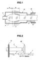
- Fig. 1 is a horizontal cross-sectional view of a float glass manufacturing apparatus for carrying out the present invention
- Fig. 2 is an enlarged view of a top roll shown in Fig. 1 as viewed from the lateral side
- Fig. 3 is an enlarged view of a part of the top roll of Fig. 1
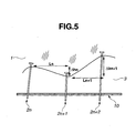
- Fig. 4 and Fig. 5 show a shape of an end portion of the glass ribbon.
- glass material is supplied from a material slot 5 onto a molten metal bath 3 in a fusion furnace 10 and is melted.
- the melted molten glass forms a pool of glass, which has a thickness near the equilibrium thickness at a high temperature range A, and is formed into a glass ribbon 1.
- the glass ribbon 1 goes ahead toward a slow cooling furnace located at the right hand side by means of a lift out roll 21, and a slow cooling roll 31 in a slow cooling furnace 30.
- the temperature range is also changed to a range B, which is slightly lower than the range A.
- the range B is a section in which the top rolls 2 exist.
- Each top roll 2 applies a tension directing in the width direction to the glass ribbon 1 by pressing an end portion of the glass ribbon by means of the teeth portion 2B thereof, as shown in Fig. 2.
- the thickness of the glass ribbon 1 is controlled.
- the glass ribbon 1 is firstly extended in the width direction by the top rolls located at the upstream side until passing through the range B. Then, the glass ribbon 1 is shaped by being slowly pressed and shrank while forming a center portion of the glass ribbon 1 into a shape having a target thickness. At this moment, it is important to control the viscosity and the shape of the glass ribbon 1.
- the viscosity at a position where the glass ribbon 1 starts being pressed and shrank that is, a range of the viscosity (unit: poise) at a position where the width of the glass ribbon 1 becomes maximal, is set from 4.5 to 5.6 inclusive.
- the range of the viscosity at a position where the width of the glass ribbon 1 becomes maximal is set from 4.5 to 5.6 inclusive. Further, from the viewpoint of manufacturing a plate from the glass ribbon, when the viscosity at the moment when the width of the glass ribbon 1 becomes maximal becomes greater than 5.6, it becomes difficult to decrease the viscosity at a section B which follows the plate manufacturing range and in which the top rolls 2 exist, and therefore the manufacture of the plate becomes difficult. Accordingly, the range of the viscosity at the moment when the width of the glass ribbon 1 becomes maximal is set from 4.5 to 5.6 inclusive.
- the following is a method for setting the viscosity of the glass ribbon 1 at the above-defined viscosity. For example, in case the viscosity is lowered, alkali component in the glass material components is increased, or a temperature in the vicinity of the range B where the top rolls 2 exist is increased. For example, in case that the viscosity is increased, the alkali component in the glass material components is decreased, or the temperature in the vicinity of the range B where the top rolls 2 exist is decreased.
- Both width directional end portions of the glass ribbon 1 are formed into a shape shown in Fig. 3, from the cause of the tension of the top rolls 2. It is important to define this shape into the following specific shape. That is, regarding at least three pairs of the top rolls 2 located downstream of the position where the width of the glass ribbon 1 becomes maximal, when a distance (unit: mm) between adjacent two top rolls 2 is L and when a variation (unit: mm) of the width directional end portion of the glass ribbon 1 to the central direction of the glass ribbon 1, at the portion where the tension of the two sets of the top rolls 2 is applied, is ⁇ h, it is preferable that -0.1 ⁇ ⁇ h/L ⁇ 0.4. The reason thereof is as follows.
- ⁇ h/L corresponds to the tension which one top roll 2 applies to the glass ribbon
- the value smaller than -0.1 excessively enlarges the pressing force which is required per one top roll 2 to apply the tension to the glass ribbon 1.
- a mark of the top roll 2 is largely remained on the glass ribbon 1.
- asperities are generated on the surface of the glass ribbon 1 and thereby generating the variation of the thickness thereof.
- the value becomes greater than 0.4, the pressing force applied by one top roll 2 is decreased. However, a difference of the asperities in the ribbon shape becomes large and an uneven thickness thereof becomes large. Accordingly, the value is set such that -0.1 ⁇ ⁇ h/L ⁇ 0.4.
- ⁇ h n /L n -( ⁇ h n+1 )/L n+1 ) represents a difference of the variations of the width directional end portions toward the central direction of the glass ribbon 1 due to the adjacent nth and n+1th top roll 2 n and 2 n+1
- the tension of the n+1th top roll 2 n+1 to the glass ribbon functions to press and shrink the glass ribbon 1 as compared with the tensions of the nth top roll 2 n and the n+2th top roll 2 n+2 .
- the value is negative as shown in Fig. 5
- it inversely functions to extend the glass ribbon 1.
- the pressing force of the n+1th top roll 2 n+1 becomes excessively large and tends to generate linear creases starting from the positions of these top rolls 2 on the surface of the glass ribbon 1.
- the remaining of the large traces of the top rolls 2 on the glass ribbon 1 results in the loss of the flatness at the central portion of the glass ribbon 1. Accordingly, the value was set such that -0.5 ⁇ ⁇ h n /L n -( ⁇ h n+1 /L n+1 ) ⁇ 0.5.
- the number of pairs of the top rolls 2 is from 5 pairs to 25 pairs inclusive. The reason thereof is as follows.
- ⁇ h/L becomes large under a condition that a distance (unit: mm) between the adjacent two top rolls 2 is L, and that a variation (unit: mm) of the width directional end portion of the glass ribbon 1 to the central direction of the glass ribbon 1, at the portion where the tension of the two sets of the top rolls 2 is applied, is ⁇ h. Therefore it becomes difficult to keep it within the preferable range.
- the number of the pairs of the top rolls 2 becomes greater than or equal to 30 pairs, the temperature in the vicinity of the end portions of the glass ribbon 1, which are contacted with the top rolls 2, is lowered. This remains the thermal strain in the glass ribbon 2, and increases the tendency of generating a large wave of the glass itself and breakage of the glass ribbon 1 in the slow cooling furnace. Further, since the top rolls 2 interfere with a window for monitoring the glass ribbon 1, it degrades the workability. Accordingly, the number of the top rolls 2 is set from 5 pairs to 25 pairs inclusive.
- the present invention is effective for microscopic thickness unevenness of float glass, and particularly aimed to satisfy the demand in quality of the lately electronic engineering use. Additionally, due to the above-mentioned means, it is possible to obtain a float glass in which a difference between the maximum thickness and the minimum thickness is 5 ⁇ m or less in measured value of an ultrasonic high-accuracy thickness meter.
- a composition of the float glass used in the method of the present invention includes material having a range of 67-73 of SiO 2 , 1-3 of Al 2 O 3 , 7-10 of CaO, 3-5 of MgO, 12-14 of Na 2 O, 0.3-1.5 of K 2 O and 0.05-0.2 Fe 2 O 3 , specified by weight percentages, which is a general-purpose soda lime composition used in building windows and in a liquid crystal substrate.
- the viscosity (unit: poise) under the temperature from 800 to 950 °C ranges from 4.5 to 6.5.
- a float glass composition used in the method of the present invention may include material having a range of 53-65 of SiO, 0-10.5 of BaO, 2-10 of Al 2 O 3 , 2-10 of CaO, 1-8 of MgO, 1-8 of Na2O, 5-10 of K 2 O, and 0.3-5 of ZrO 2 , represented by weight percentages, which is the glass composition used in PDP substrate and the like.
- the viscosity (unit: poise) under the temperature from 900 to 1100 °C ranges from 4.5 to 6.5.
- a glass ribbon is formed on the molten metal.
- the employed top roll is a general use set which has a rotation gear made of heat-resistance and corrosion-resistance alloy.
- the shape of the glass ribbons were controlled.
- the glass composition is a general-purpose soda lime composition used in building windows and in a liquid crystal substrate, and is represented by 71% of SiO 2 , 2% of Al 2 O 3 , 9% of CaO, 4% of MgO, 13% of Na 2 O and 1% of K 2 O of weight percentages.
- the viscosity As to the viscosity, a viscosity of the glass having the same composition was measured in an experimental laboratory, it was controlled by controlling the temperature in the molten furnace, and the controlled value was shown in TABLE 1. The measurement thereof was carried out according to ISO 7884-2:1987 (Glass - Viscosity and viscometric fixed points - Part 2: Determination of viscosity by rotation viscometers). The thickness unevenness was a value of a difference between the maximum thickness and the minimum thickness of thickness measured at 5 inch pitches by means of an ultrasonic high-accuracy thickness meter (MODEL25DL of Japan Panametrics Co., Ltd.).
- Example 2 Except that ⁇ h n /L n -( ⁇ h n+1 /L n+1 ) and the number of the top rolls are different from those of Example 1, the float glass was manufactured with the same manner of Example, and the measurements as same as those of measured with of EXAMPLE 1 were carried out. The results thereof were shown in TABLE 2.
- the employed glass composition was a composition for liquid crystal substrate, PDP substrate, and thin-film transistor.
- the employed composition is represented by 54 % of SiO2, 10 % of BaO, 9 % of A 12 O 3 , 8 % of CaO, 3 % of MgO, 4 % of Na 2 O, 9 % of K 2 O, and 4% of ZrO 2 , which were represented by weight percentages.
- the shape of the glass ribbon was controlled by controlling the advancing speed, the pressing force of the top rolls, the width directional positions and the number of the top rolls, the temperature and the viscosity of the glass ribbon located near the top roll existing area.
Landscapes
- Chemical & Material Sciences (AREA)
- Engineering & Computer Science (AREA)
- Materials Engineering (AREA)
- Organic Chemistry (AREA)
- Mechanical Engineering (AREA)
- Glass Compositions (AREA)
Abstract
The present invention relates to a method of manufacturing float glass, which is characterized in that in a method of manufacturing float glass of a thickness from 0.1 to 3 mm, during a process of controlling a width of a glass ribbon by means of top rolls, a viscosity of the glass ribbon located at a position where the width of the glass ribbon becomes maximal ranges from 4.5 to 5.6 inclusive, and regarding at least three top rolls located downstream of the position where the width of the glass ribbon becomes maximal, when a distance (unit: mm) between adjacent two top rolls is L and when a variation (unit: mm) of the width directional end portion of the glass ribbon to the central direction of the glass ribbon, at the portion where the tension of the two top rolls is applied, is Δh, -0.1 ≤ Δh/L ≤ 0.4 is established.
Description
- The present invention relates to a method of manufacturing float glass.
- In manufacturing float glass, by floating molten glass material on a molten metal, the molten glass material naturally spreads and has a stable thickness as a result of equilibrium between the surface tensile and the gravity of the molten glass. A thickness at this state is referred to as an equilibrium thickness. The molten glass is drugged along the one direction into a ribbon shape so as to form a glass ribbon. In case that a desired thickness is thinner than the equilibrium thickness, there is generally applied a method of thinning the glass ribbon by extending the glass ribbon in the width direction in a manner of pressing rotating rolls, each of which has grooves and gears and is referred to as top roll (for example, see a patent document 1).
- Since the glass ribbon floats on a molten metal bath, by controlling a pressing force and a direction of the top roll, and a quantity and a viscosity of the glass ribbon, it should be principally obtained a plate glass having a desired thickness which is thinner than the equilibrium thickness.
- However, even if it is possible to control an overall thickness, there are locally existed microscopic asperities. Although there are considered a case that unevenness of the thickness directly generates the asperities (so-called uneven thickness) and a case that the plate totally waves while keeping the thickness constant as a cause of the microscopic asperities, the former cause is generally attributed as to the microscopic asperities. It is considered that the microscopic asperities are generated during a process of extending the glass ribbon in the width direction by means of top rolls so as to thin it.
- That is to say, although a part of the glass ribbon in a line with a part extended by the top rolls tends to become thinner, a portion between the adjacent top rolls tends to become thicker so as to return the equilibrium thickness. Further, although the glass ribbon itself moves in the direction perpendicular to the width direction, the top rolls do not move. Accordingly, the extended portion of the glass ribbon extended by the top rolls moves every second in view of the glass ribbon. That is, it is easily understood that the glass ribbon receives a complex stress, which changes every second and which generates micro deformations thereby and thickness unevenness due to the deformations.
- There has been tried to solve such thickness unevenness. For example, on the assumption that the reason thereof is that the tension is applied at portions at which the top rolls are separately disposed, there has been proposed that the tension is continuously applied along the end portions of the glass ribbon, instead of the top rolls (for example, see a patent document 2). However, this could not completely eliminate the thickness unevenness finally. It seems that since the glass ribbon moves toward the downstream side, the tension is not parallel with the width direction and is forcibly put in a slightly inclined direction toward the advancing direction, and therefore, the tension cannot function to equivalently extend the glass ribbon.
- Further, there has been a proposal that although the end portions of the glass ribbon receiving the tension of the top rolls have the roll traces and are not used as a product, by increasing the thickness at the end portion to about 3 mm or less with respect to the thickness from 0.1 through 1.5 mm of the central portion and by increasing the width, the stress-strain is eased and the asperities of the glass surface are decreased (for example, see a patent document 3).
- The thickness unevenness becomes negligible in some use by deceasing it to a predetermined degree. For example, in case of window glasses for buildings and vehicles, by decreasing it to a degree that a transmission image through a glass is not distorted to the naked eye, there is nothing wrong. However, in recent years, the demand as to the quality in the electronic engineering use such as PDP substrate, liquid crystal substrate, solar cell substrate and the like have become increasingly severe. Therefore, it becomes difficult to obtain the product getting through this grade only using known art. Although there is known a technique for polishing the glass surface on the presumption that there are existed asperities on the glass surface, this apparently increases the cost of a product.
Under such a condition, there has been desired a method which is capable of easily obtaining a plate glass having no microscopic thickness unevenness. - Patent document 1:
Japanese Examined Patent Application Publication No. (Showa) 44-23823 - Patent document 2:
Japanese Examined Patent Application Publication No. (Showa) 49-5206 - Patent document 3:
Japanese Published Patent Application No (Heisei) 7-10569 - For example, although information described in the
Japanese Examined Patent Application No. (Showa) 49-5206 - Further, an apparatus described in the Japanese Published Patent Application No. (Heisei) 7-10569 is arranged to solve the microscopic asperities by increasing a thickness at end portions of the glass ribbon to be thicker than that of the central portion and to be thinner than about 3 mm and by increasing the width, the stress-strain is eased so as to solve the microscopic asperities. However, since the end portions do not used as products, a part for the product is decreased as the width is increased. That is, there is a problem that the quantity of the products decreases as it is aimed to manufacture better products. Further, if the thickness at the end portion becomes largely different from the thickness at the central portion, the difference of the heat capacities is certainly generated. Therefore, there is caused a possibility that the glass ribbon tends to be easily broken in the slow cooling furnace and that the heat strain at this part functions as a cause of new asperities. Further, since this method is arranged to ease the strain, it is considered that although it is effective to a whole wave of the plate glass due to the strain, it is not always effective to the plate thickness unevenness (uneven thickness) due to the deviation of the material.
- Thus, it is incapable of saying that there has been developed a method of easily obtaining thickness-unevenness-less plate glass which satisfies the recent quality demand.
- According to the present invention, there is proposed a method of manufacturing float glass, which is characterized in that in a method of manufacturing float glass of a thickness from 0.1 to 3 mm, during a process of controlling a width of a glass ribbon by means of top rolls, a viscosity of the glass ribbon located at a position where the width of the glass ribbon becomes maximal ranges from 4.5 to 5. 6 inclusive, and regarding at least three top rolls located downstream of the position where the width of the
glass ribbon 1 becomes maximal, when a distance (unit: mm) between adjacent twotop rolls 2 is L and when a variation (unit: mm) of the width directional end portion of the glass ribbon to the central direction of the glass ribbon, at the portion where the tension of the two top rolls is applied, is Δh, -0.1 ≤ Δh/L ≤ 0.4 is established. -
- [Fig. 1] It is a horizontal cross-sectional view of an apparatus for carrying out the present invention.
- [Fig. 2] It is an enlarged cross-sectional view of a top roll.
- [Fig. 3] It is an enlarged view of an end portion of a glass ribbon in Fig. 1.
- [Fig. 4] It is a partially extracted view of Fig. 3, for explaining a change of a shape of the glass ribbon end portion due to the top roll.
- [Fig. 5] It is a view similar to Fig. 4, in case that a tension of the top roll is differentiated.
- The present invention is applicable to a field of a plate glass conventionally utilized in window glasses for buildings and window glasses for vehicles, and particularly to a field of electronic material requiring a smoothness of a surface for PDP substrate, crystalline substrate and solar battery substrate and the like.
- According to the present invention, it becomes possible to obtain a float glass, which has extremely little thickness unevenness and which is applicable to a use in the electronic engineering of PDP substrate, crystalline substrate and solar battery substrate and the like. Further, it is possible to manufacture float glass under a stable operation, while improving the quality and the yield of the float glass, without largely changing an operating condition and a plate manufacturing condition of an actual ceramic industry in a float method and without preparing new equipment.
- The present invention is for obtaining float glass having less thickness unevenness, by defining the viscosity of the glass ribbon at a time when a width of the glass ribbon becomes maximal during a glass manufacturing process, a shape of the glass ribbon, and a top roll condition for controlling the shape.
- Hereinafter, there is explained the invention on the basis of the drawings. Fig. 1 is a horizontal cross-sectional view of a float glass manufacturing apparatus for carrying out the present invention, Fig. 2 is an enlarged view of a top roll shown in Fig. 1 as viewed from the lateral side, Fig. 3 is an enlarged view of a part of the top roll of Fig. 1, and Fig. 4 and Fig. 5 show a shape of an end portion of the glass ribbon.
- As shown in Fig. 1, glass material is supplied from a
material slot 5 onto amolten metal bath 3 in afusion furnace 10 and is melted. The melted molten glass forms a pool of glass, which has a thickness near the equilibrium thickness at a high temperature range A, and is formed into aglass ribbon 1. Theglass ribbon 1 goes ahead toward a slow cooling furnace located at the right hand side by means of a lift outroll 21, and aslow cooling roll 31 in aslow cooling furnace 30. The temperature range is also changed to a range B, which is slightly lower than the range A. The range B is a section in which the top rolls 2 exist. 5 through 25 pairs of top rolls are arranged so that the number, the direction, a pressure of pressing the glass ribbon and a speed of the respective top rollers are variable. In case of obtaining a glass ribbon having a thickness thinner than the equilibrium thickness, the glass ribbon is extended. Therefore, rotation shafts of each pair of the top rolls are arranged so as to be slightly inclined in the advancing direction of theglass ribbon 1. - Each
top roll 2 applies a tension directing in the width direction to theglass ribbon 1 by pressing an end portion of the glass ribbon by means of theteeth portion 2B thereof, as shown in Fig. 2. By suppressing width shrinkage of theglass ribbon 1, the thickness of theglass ribbon 1 is controlled. - The
glass ribbon 1 is firstly extended in the width direction by the top rolls located at the upstream side until passing through the range B. Then, theglass ribbon 1 is shaped by being slowly pressed and shrank while forming a center portion of theglass ribbon 1 into a shape having a target thickness. At this moment, it is important to control the viscosity and the shape of theglass ribbon 1. - That is to say, the viscosity at a position where the
glass ribbon 1 starts being pressed and shrank, that is, a range of the viscosity (unit: poise) at a position where the width of theglass ribbon 1 becomes maximal, is set from 4.5 to 5.6 inclusive. - In case that the viscosity at the position where the width of the
glass ribbon 1 becomes maximal is low, the thickness unevenness of theglass ribbon 1 and seams due to the tension of thetop roll 2, which have once generated, naturally disappear due to the gravity. However, when the viscosity (unit: poise) becomes greater than 5.6, they are not completely disappeared and tend to be remained. Inversely, when the viscosity becomes smaller than 4.5, although it is advantageous in view that the thickness unevenness of theglass ribbon 1 and seams due to the tension of the top roll, which have once generated, naturally disappear due to the gravity, the tension due to thetop roll 2 tends to become inoperative, and it becomes difficult to control the thickness of theglass ribbon 1. Therefore, it is preferable that the range of the viscosity at a position where the width of theglass ribbon 1 becomes maximal, is set from 4.5 to 5.6 inclusive. Further, from the viewpoint of manufacturing a plate from the glass ribbon, when the viscosity at the moment when the width of theglass ribbon 1 becomes maximal becomes greater than 5.6, it becomes difficult to decrease the viscosity at a section B which follows the plate manufacturing range and in which the top rolls 2 exist, and therefore the manufacture of the plate becomes difficult. Accordingly, the range of the viscosity at the moment when the width of theglass ribbon 1 becomes maximal is set from 4.5 to 5.6 inclusive. - The following is a method for setting the viscosity of the
glass ribbon 1 at the above-defined viscosity. For example, in case the viscosity is lowered, alkali component in the glass material components is increased, or a temperature in the vicinity of the range B where the top rolls 2 exist is increased. For example, in case that the viscosity is increased, the alkali component in the glass material components is decreased, or the temperature in the vicinity of the range B where the top rolls 2 exist is decreased. - Both width directional end portions of the
glass ribbon 1 are formed into a shape shown in Fig. 3, from the cause of the tension of the top rolls 2. It is important to define this shape into the following specific shape. That is, regarding at least three pairs of the top rolls 2 located downstream of the position where the width of theglass ribbon 1 becomes maximal, when a distance (unit: mm) between adjacent twotop rolls 2 is L and when a variation (unit: mm) of the width directional end portion of theglass ribbon 1 to the central direction of theglass ribbon 1, at the portion where the tension of the two sets of the top rolls 2 is applied, is Δh, it is preferable that -0.1≤ Δh/L ≤0.4. The reason thereof is as follows. - Although Δh/L corresponds to the tension which one
top roll 2 applies to the glass ribbon, the value smaller than -0.1 excessively enlarges the pressing force which is required per onetop roll 2 to apply the tension to theglass ribbon 1. As a result, a mark of thetop roll 2 is largely remained on theglass ribbon 1. Further, asperities are generated on the surface of theglass ribbon 1 and thereby generating the variation of the thickness thereof. Further, although it is possible to decrease the tension of each one set to the glass ribbon by increasing the number of the top rolls 2, the control thereof becomes difficult and has a limit. - When the value becomes greater than 0.4, the pressing force applied by one
top roll 2 is decreased. However, a difference of the asperities in the ribbon shape becomes large and an uneven thickness thereof becomes large. Accordingly, the value is set such that -0.1 ≤ Δh/L ≤ 0.4. - It is possible to control the value within this range by adjusting the direction, the pressing force and the rotation speed of each of the top rolls 2.
- As shown in Fig. 4 and Fig. 5, regarding al least three sets of the top rolls 2 located downstream of the position where the width of the
glass ribbon 1 becomes maximal, when a distance (unit: mm) between the adjacent nthtop roll 2n and the adjacent n+1thtop roll 2n+1 ordered toward the downstream side is Ln, and when a variation (unit: mm) of the width directional end portion of theglass ribbon 1 to the central direction of theglass ribbon 1, at the portion where the tensions of the twotop rolls top roll 2n+1 and n+2thtop roll 2n+2 ordered toward the downstream side is Ln+1, and when a variation of the width directional end portion of theglass ribbon 1 to the central direction of theglass ribbon 1, at the portion where the tension of the twotop rolls - Although Δhn/Ln-(Δhn+1)/Ln+1) represents a difference of the variations of the width directional end portions toward the central direction of the
glass ribbon 1 due to the adjacent nth and n+1thtop roll top roll 2n+1 to the glass ribbon functions to press and shrink theglass ribbon 1 as compared with the tensions of the nthtop roll 2n and the n+2thtop roll 2n+2. In case that the value is negative as shown in Fig. 5, it inversely functions to extend theglass ribbon 1. If the value becomes out of the above-mentioned range, the pressing force of the n+1thtop roll 2n+1 becomes excessively large and tends to generate linear creases starting from the positions of thesetop rolls 2 on the surface of theglass ribbon 1. The remaining of the large traces of the top rolls 2 on theglass ribbon 1 results in the loss of the flatness at the central portion of theglass ribbon 1. Accordingly, the value was set such that -0.5≤ Δhn/Ln-(Δhn+1/Ln+1) ≤ 0.5. - As a method of controlling the value within the above-discussed range, there is proposed to control the direction, the pressing force and the rotation speed of the
top roll 2 or to control the distance between thetop rolls 2 and the number of the top rolls 2. - It is preferable that the number of pairs of the top rolls 2 is from 5 pairs to 25 pairs inclusive. The reason thereof is as follows.
- If the number of the pairs of the top rolls 2 becomes smaller than or equal to 4 pairs, the pressing force of the
top roll 2 per each pair, necessary for applying the tension to theglass ribbon 1 becomes excessively large. As a result the large traces of the top rolls 2 remain and the flatness of the glass ribbon is lost. Further as discussed above, Δh/L becomes large under a condition that a distance (unit: mm) between the adjacent twotop rolls 2 is L, and that a variation (unit: mm) of the width directional end portion of theglass ribbon 1 to the central direction of theglass ribbon 1, at the portion where the tension of the two sets of the top rolls 2 is applied, is Δh. Therefore it becomes difficult to keep it within the preferable range. Inversely, if the number of the pairs of the top rolls 2 becomes greater than or equal to 30 pairs, the temperature in the vicinity of the end portions of theglass ribbon 1, which are contacted with the top rolls 2, is lowered. This remains the thermal strain in theglass ribbon 2, and increases the tendency of generating a large wave of the glass itself and breakage of theglass ribbon 1 in the slow cooling furnace. Further, since the top rolls 2 interfere with a window for monitoring theglass ribbon 1, it degrades the workability. Accordingly, the number of the top rolls 2 is set from 5 pairs to 25 pairs inclusive. - The present invention is effective for microscopic thickness unevenness of float glass, and particularly aimed to satisfy the demand in quality of the lately electronic engineering use. Additionally, due to the above-mentioned means, it is possible to obtain a float glass in which a difference between the maximum thickness and the minimum thickness is 5 µm or less in measured value of an ultrasonic high-accuracy thickness meter.
- Further, a composition of the float glass used in the method of the present invention includes material having a range of 67-73 of SiO2, 1-3 of Al2O3, 7-10 of CaO, 3-5 of MgO, 12-14 of Na2O, 0.3-1.5 of K2O and 0.05-0.2 Fe2O3, specified by weight percentages, which is a general-purpose soda lime composition used in building windows and in a liquid crystal substrate. In case of this composition, the viscosity (unit: poise) under the temperature from 800 to 950 °C ranges from 4.5 to 6.5. By controlling the temperature at the same temperature range in the float bath, it becomes possible to obtain the float glass, which has extremely little thickness unevenness.
- Further, a float glass composition used in the method of the present invention may include material having a range of 53-65 of SiO, 0-10.5 of BaO, 2-10 of Al2O3, 2-10 of CaO, 1-8 of MgO, 1-8 of Na2O, 5-10 of K2O, and 0.3-5 of ZrO2, represented by weight percentages, which is the glass composition used in PDP substrate and the like. In case of this composition, the viscosity (unit: poise) under the temperature from 900 to 1100 °C ranges from 4.5 to 6.5. By controlling the temperature at the same temperature range in the float bath, it becomes possible to obtain the float glass, which has extremely little thickness unevenness.
- The following non-limited example exemplifies the present invention.
- By introducing molten glass into a melted metal bath of about 50 m in length, which has being constructed such that the cooled ribbon has about 4 m in width, a glass ribbon is formed on the molten metal. The employed top roll is a general use set which has a rotation gear made of heat-resistance and corrosion-resistance alloy. In manufacturing the glass ribbon, as to
samples 1 through 10, by controlling the advancing speed, the pressing force of the top roll, the lateral position and the number of the top rolls, and the temperature and the viscosity of the glass ribbon near the area in which the top rolls exist according to the conditions shown in TABLE 1, the shape of the glass ribbons were controlled. - The glass composition is a general-purpose soda lime composition used in building windows and in a liquid crystal substrate, and is represented by 71% of SiO2, 2% of Al2O3, 9% of CaO, 4% of MgO, 13% of Na2O and 1% of K2O of weight percentages.
- In TABLE 1, there were shown a set thickness (unit: mm) at a central portion; a viscosity (unit: poise) at a part where the glass ribbon has the maximum width, Δh/L under a condition that a distance (unit: mm) between the top rolls is L and a variation (unit: mm) of the width directional end portion of the glass ribbon to the central direction of the glass ribbon is Δh; Δhn/Ln-(Δhn+1/Ln+1) under a condition that a variation (unit: mm) of the width directional end portion of the glass ribbon 1 to the central direction of the glass ribbon 1, at the portion where the tension of the two top rolls 2n and 2n+1 is applied, is Δhn, and a distance (unit: mm) between adjacent the n+1th top roll 2n+1 and the n+2th top roll 2n+2 ordered toward the downstream side is Ln+1, and when a variation (unit: mm) of the width directional end portion of the glass ribbon 1 to the central direction of the glass ribbon 1, at the portion where the tension of the two top rolls 2n+1 and 2n+2 is applied, is Δhn+1; a number of the top rolls; and a maximum thickness unevenness (unit: µm) of a glass cut into 500 mm x 500 mm square of the central portion of the finally obtained float glass. As to the viscosity, a viscosity of the glass having the same composition was measured in an experimental laboratory, it was controlled by controlling the temperature in the molten furnace, and the controlled value was shown in TABLE 1. The measurement thereof was carried out according to ISO 7884-2:1987 (Glass - Viscosity and viscometric fixed points - Part 2:
Determination of viscosity by rotation viscometers). The thickness unevenness was a value of a difference between the maximum thickness and the minimum thickness of thickness measured at 5 inch pitches by means of an ultrasonic high-accuracy thickness meter (MODEL25DL of Japan Panametrics Co., Ltd.). - Except that Δhn/Ln-(Δhn+1/Ln+1) and the number of the top rolls are different from those of Example 1, the float glass was manufactured with the same manner of Example, and the measurements as same as those of measured with of EXAMPLE 1 were carried out. The results thereof were shown in TABLE 2.
-
[TABLE 1] Set thickness Viscosity Δh/L Δhn/Ln -Δhn+1/Ln+1 Number of top rolls Thickness unevenness (mm) (poise) (pair) (µm) 1 2.8 5.3 0.1~0.3 0.0∼0.3 10 4 2 2.8 5.1 0.0~0.3 0.0∼0.3 10 4 3 2.3 5.3 0.1~0.3 0.0∼0.3 10 3 4 2.3 5.1 0.0~0.3 0.0∼0.2 10 4 5 1.8 5.3 0.0~0.3 0.0∼0.2 10 3 6 1.8 5.1 0.0~0.3 0.0∼0.3 10 4 7 1.0 5.1 0.0~0.3 0.0∼0.2 15 4 8 1.0 5.0 0.0~0.3 -0.1~0.2 15 4 9 0.5 5.1 -0.1~0.3 -0.1~0.3 24 5 10 0.5 5.0 -0.1~0.3 -0.1~0.4 20 5 -
[TABLE 2] Set thickness Viscosity Δh/L Δhn/Ln -Δhn+1/Ln+1 Number of top rolls Thickness unevenness (mm) (poise) (pair) (µm) 1 2.8 5.3 0.1~0.5 0.0∼0.3 10 7 2 2.8 5.1 -0.1~0.5 -0.1~0.6 10 7 3 2.3 5.3 0.1~0.5 0.0∼0.3 10 8 4 2.3 5.1 -0.2∼0.5 -0.5∼0.6 10 6 5 1.8 5.3 -0.2∼0.5 0.0∼0.6 10 7 6 1.8 4.4 0.0∼0.3 0.0∼0.2 10 7 7 1.0 5.1 -0.2∼0.5 0.0∼0.6 15 9 8 1.0 5.0 -0.2∼0.3 -0.1~0.2 15 8 9 0.5 5.7 -0.1~0.2 -0.1~0.2 27 12 10 0.5 5.0 -0.2∼0.2 -0.1~0.3 29 15 - The employed glass composition was a composition for liquid crystal substrate, PDP substrate, and thin-film transistor. The employed composition is represented by 54 % of SiO2, 10 % of BaO, 9 % of A12O3, 8 % of CaO, 3 % of MgO, 4 % of Na2O, 9 % of K2O, and 4% of ZrO2, which were represented by weight percentages.
- In forming the glass ribbon, the shape of the glass ribbon was controlled by controlling the advancing speed, the pressing force of the top rolls, the width directional positions and the number of the top rolls, the temperature and the viscosity of the glass ribbon located near the top roll existing area.
- The sample of a plate glass cut out from the cooled ribbon was evaluated with the same method of EXAMPLE 1. The results thereof are shown in TABLE 3.
- Except that Δhn/Ln-(Δhn+1/Ln+1) and the number of the top rolls were different from those of EXAMPLE 2, the float glass was manufactured with the same manner of EXAMPLE 2, and the measurements as same as those of measured with of EXAMPLE 2 were carried out. The results thereof were shown in TABLE 4.
-
[TABLE 3] Set Thickness Viscosity Δh/L Δhn/Ln -Δhn+1/Ln+1 Number of top rolls Thickness unevenness (mm) (poise) (pair) (µm) 1 2.8 5.2 0.1~0.3 0.0∼0.3 10 3 2 2.8 5.0 0.0~0.3 0.0∼0.3 10 4 3 2.3 5.2 0.1~0.3 0.0∼0.3 10 4 4 2.3 5.0 0.0~0.3 0.0∼0.2 10 4 5 1.8 5.2 0.0~0.3 0.0∼0.2 10 3 6 1.8 5.0 0.0~0.3 0.0∼0.3 10 4 7 1.0 5.2 0.0~0.3 0.0∼0.2 15 4 8 1.0 5.0 0.0~0.3 -0.0∼0.2 15 4 -
[TABLE 4] Set thickness Viscosity Δh/L Δhn/Ln -Δhn+1/Ln+1 Number of top rolls Thickness unevenness (mm) (poise) (pair) (µm) 1 2.8 5.2 -0.2∼0.3 0.0∼0.3 10 (crack) 2 2.8 5.0 -0.2~0.4 -0.1~0.6 10 8 3 2.3 5.7 -0.1~0.3 -0.1~0.3 10 7 4 2.3 5.0 -0.2~0.5 -0.5-0.6 10 (crack) 5 1.8 5.2 -0.2~0.5 -0.1~0.6 10 8 6 1.8 4.4 -0.1~0.4 -0.1~0.5 10 8 7 1.0 5.2 -0.2∼0.5 -0.1~0.6 15 10 8 1.0 5.0 -0.2∼0.4 -0.1~0.4 15 9 - As is apparent from each EXAMPLE, there is manufactured a float glass, whose surface has extremely little thickness unevenness such that the thickness unevenness of 500 mm × 500 mm square is 5 µm or less.
Claims (3)
- In a method of manufacturing float glass of a thickness from 0.1 to 3 mm, the method of manufacturing the float glass characterized in that during a process of controlling a width of a glass ribbon by means of top rolls, a viscosity of the glass ribbon located at a position where the width of the glass ribbon becomes maximal ranges from 4. 5 to 5. 6 inclusive, and regarding at least three top rolls located downstream of the position where the width of the glass ribbon becomes maximal, when a distance (unit: mm) between adjacent two top rolls is L and when a variation (unit: mm) of the width directional end portion of the glass ribbon to the central direction of the glass ribbon, at the portion where the tension of the two top rolls is applied, is Δh, -0.1≤ Δh/L≤ 0.4 is established.
- A method of manufacturing float glass as claimed in claim 1, characterized in that regarding al least three top rolls located downstream of the position where the width of the glass ribbon becomes maximal, when a distance (unit: mm) between the adjacent nth top roll and n+1th top roll ordered toward the downstream side is Ln, and when a variation (unit: mm) of the width directional end portion of the glass ribbon to the central direction of the glass ribbon, at the portion where the tensions of the two top rolls are applied, is Δhn, and further when a distance (unit: mm) between the adjacent n+1th top roll and n+2th top roll ordered toward the downstream side is Ln+1, and when a variation of the width directional end portion of the glass ribbon to the central direction of the glass ribbon, at the portion where the tension of the two top rolls is applied, is Δhn+1,-0.5≤ Δhn/Ln-(Δhn+1)/Ln+1) ≤ 0.5 is established.
- A method of manufacturing float glass as claimed in one of claims 1 and 2, wherein the number of the top rolls ranges from 5 pairs to 25 pairs inclusive.
Applications Claiming Priority (2)
| Application Number | Priority Date | Filing Date | Title |
|---|---|---|---|
| JP2004082205A JP4520192B2 (en) | 2004-03-22 | 2004-03-22 | Method for producing float glass sheet |
| PCT/JP2005/004971 WO2005090245A1 (en) | 2004-03-22 | 2005-03-18 | Method of manufacturing float plate glass |
Publications (1)
| Publication Number | Publication Date |
|---|---|
| EP1739062A1 true EP1739062A1 (en) | 2007-01-03 |
Family
ID=34993592
Family Applications (1)
| Application Number | Title | Priority Date | Filing Date |
|---|---|---|---|
| EP05726719A Withdrawn EP1739062A1 (en) | 2004-03-22 | 2005-03-18 | Method of manufacturing float plate glass |
Country Status (5)
| Country | Link |
|---|---|
| EP (1) | EP1739062A1 (en) |
| JP (1) | JP4520192B2 (en) |
| KR (1) | KR100756399B1 (en) |
| CN (1) | CN1934037B (en) |
| WO (1) | WO2005090245A1 (en) |
Cited By (3)
| Publication number | Priority date | Publication date | Assignee | Title |
|---|---|---|---|---|
| EP2377821A1 (en) * | 2010-04-15 | 2011-10-19 | Asahi Glass Company, Limited | Float glass manufacturing apparatus and float glass manufacturing method |
| US8720227B2 (en) | 2007-11-01 | 2014-05-13 | Central Glass Company, Limited | Conveyance assisting device of glass ribbon |
| WO2015164554A1 (en) * | 2014-04-24 | 2015-10-29 | Corning Incorporated | Glass manufacturing apparatus and methods |
Families Citing this family (7)
| Publication number | Priority date | Publication date | Assignee | Title |
|---|---|---|---|---|
| JP4811647B2 (en) * | 2006-01-17 | 2011-11-09 | 独立行政法人産業技術総合研究所 | Manufacturing method of glass molded product |
| JPWO2009107453A1 (en) * | 2008-02-29 | 2011-06-30 | 日本板硝子株式会社 | Glass substrate for display device, liquid crystal display panel, and liquid crystal display device |
| JP5565127B2 (en) * | 2010-06-17 | 2014-08-06 | 旭硝子株式会社 | Glass plate manufacturing apparatus and manufacturing method |
| CN105776824A (en) * | 2011-11-17 | 2016-07-20 | 旭硝子株式会社 | Molding method for plate glass |
| KR102045834B1 (en) * | 2012-04-12 | 2019-11-18 | 에이지씨 가부시키가이샤 | Method and device for manufacturing glass plate |
| WO2013157477A1 (en) * | 2012-04-17 | 2013-10-24 | 旭硝子株式会社 | Glass plate manufacturing device and manufacturing method |
| KR102166471B1 (en) * | 2017-09-20 | 2020-10-16 | 주식회사 엘지화학 | Apparatus and Method for manufacturing glass substrate |
Family Cites Families (4)
| Publication number | Priority date | Publication date | Assignee | Title |
|---|---|---|---|---|
| JP3572631B2 (en) * | 1993-06-25 | 2004-10-06 | 旭硝子株式会社 | Manufacturing method of float plate glass |
| JPH0826755A (en) * | 1994-07-21 | 1996-01-30 | Asahi Glass Co Ltd | Edge roll device for float glass manufacturing |
| FR2747119B1 (en) * | 1996-04-05 | 1998-05-07 | Saint Gobain Vitrage | METHOD FOR MANUFACTURING SHEET GLASS BY FLOATING |
| JP4095206B2 (en) * | 1999-06-29 | 2008-06-04 | ヤマハ株式会社 | Waveform generating method and apparatus |
-
2004
- 2004-03-22 JP JP2004082205A patent/JP4520192B2/en not_active Expired - Fee Related
-
2005
- 2005-03-18 EP EP05726719A patent/EP1739062A1/en not_active Withdrawn
- 2005-03-18 KR KR1020067019427A patent/KR100756399B1/en not_active Expired - Fee Related
- 2005-03-18 WO PCT/JP2005/004971 patent/WO2005090245A1/en not_active Ceased
- 2005-03-18 CN CN2005800093151A patent/CN1934037B/en not_active Expired - Fee Related
Non-Patent Citations (1)
| Title |
|---|
| See references of WO2005090245A1 * |
Cited By (4)
| Publication number | Priority date | Publication date | Assignee | Title |
|---|---|---|---|---|
| US8720227B2 (en) | 2007-11-01 | 2014-05-13 | Central Glass Company, Limited | Conveyance assisting device of glass ribbon |
| EP2377821A1 (en) * | 2010-04-15 | 2011-10-19 | Asahi Glass Company, Limited | Float glass manufacturing apparatus and float glass manufacturing method |
| WO2015164554A1 (en) * | 2014-04-24 | 2015-10-29 | Corning Incorporated | Glass manufacturing apparatus and methods |
| US10343943B2 (en) | 2014-04-24 | 2019-07-09 | Corning Incorporated | Glass manufacturing apparatus and methods |
Also Published As
| Publication number | Publication date |
|---|---|
| KR100756399B1 (en) | 2007-09-10 |
| KR20060117373A (en) | 2006-11-16 |
| CN1934037A (en) | 2007-03-21 |
| WO2005090245A1 (en) | 2005-09-29 |
| JP2005263602A (en) | 2005-09-29 |
| JP4520192B2 (en) | 2010-08-04 |
| CN1934037B (en) | 2010-05-05 |
Similar Documents
| Publication | Publication Date | Title |
|---|---|---|
| US11420898B2 (en) | High strength ultrathin glass and method of making the same | |
| KR102647478B1 (en) | Method and apparatus for manufacturing thin glass, and thin glass ribbon | |
| EP3802449B1 (en) | Glass with improved drop performance | |
| US11932574B2 (en) | Lithium containing glasses | |
| KR101300909B1 (en) | Method and apparatus for making glass sheet | |
| CN102869622B (en) | Glass plate manufacturing method and glass plate manufacturing apparatus | |
| EP3535219B1 (en) | Lithium containing glasses | |
| JP2009107913A (en) | Method for manufacturing float plate glass | |
| EP1739062A1 (en) | Method of manufacturing float plate glass | |
| EP3204338A2 (en) | Glasses and glass ceramics including a metal oxide concentration gradient | |
| JPH0710569A (en) | Float plate glass manufacturing method | |
| CN111943503A (en) | Preparation method of high-hardness ultrathin float glass | |
| JP2009107914A (en) | Process for producing float plate glass | |
| CN112777930A (en) | Glass, glass forming method, pressing device and calender | |
| US20230143992A1 (en) | Fusion formable high fracture toughness glasses |
Legal Events
| Date | Code | Title | Description |
|---|---|---|---|
| PUAI | Public reference made under article 153(3) epc to a published international application that has entered the european phase |
Free format text: ORIGINAL CODE: 0009012 |
|
| 17P | Request for examination filed |
Effective date: 20060920 |
|
| AK | Designated contracting states |
Kind code of ref document: A1 Designated state(s): DE FR GB |
|
| DAX | Request for extension of the european patent (deleted) | ||
| RBV | Designated contracting states (corrected) |
Designated state(s): DE FR GB |
|
| RBV | Designated contracting states (corrected) |
Designated state(s): DE FR GB |
|
| STAA | Information on the status of an ep patent application or granted ep patent |
Free format text: STATUS: THE APPLICATION HAS BEEN WITHDRAWN |
|
| 18W | Application withdrawn |
Effective date: 20100920 |