EP1738704A1 - Ultrasonic treatment tool - Google Patents
Ultrasonic treatment tool Download PDFInfo
- Publication number
- EP1738704A1 EP1738704A1 EP04821908A EP04821908A EP1738704A1 EP 1738704 A1 EP1738704 A1 EP 1738704A1 EP 04821908 A EP04821908 A EP 04821908A EP 04821908 A EP04821908 A EP 04821908A EP 1738704 A1 EP1738704 A1 EP 1738704A1
- Authority
- EP
- European Patent Office
- Prior art keywords
- ultrasonic
- treatment apparatus
- ultrasonic treatment
- unit
- endoscope
- Prior art date
- Legal status (The legal status is an assumption and is not a legal conclusion. Google has not performed a legal analysis and makes no representation as to the accuracy of the status listed.)
- Withdrawn
Links
Images




Classifications
-
- A—HUMAN NECESSITIES
- A61—MEDICAL OR VETERINARY SCIENCE; HYGIENE
- A61B—DIAGNOSIS; SURGERY; IDENTIFICATION
- A61B17/00—Surgical instruments, devices or methods
- A61B17/32—Surgical cutting instruments
- A61B17/320068—Surgical cutting instruments using mechanical vibrations, e.g. ultrasonic
-
- A—HUMAN NECESSITIES
- A61—MEDICAL OR VETERINARY SCIENCE; HYGIENE
- A61B—DIAGNOSIS; SURGERY; IDENTIFICATION
- A61B34/00—Computer-aided surgery; Manipulators or robots specially adapted for use in surgery
- A61B34/70—Manipulators specially adapted for use in surgery
- A61B34/71—Manipulators operated by drive cable mechanisms
-
- A—HUMAN NECESSITIES
- A61—MEDICAL OR VETERINARY SCIENCE; HYGIENE
- A61B—DIAGNOSIS; SURGERY; IDENTIFICATION
- A61B17/00—Surgical instruments, devices or methods
- A61B17/22—Implements for squeezing-off ulcers or the like on inner organs of the body; Implements for scraping-out cavities of body organs, e.g. bones; for invasive removal or destruction of calculus using mechanical vibrations; for removing obstructions in blood vessels, not otherwise provided for
- A61B17/22004—Implements for squeezing-off ulcers or the like on inner organs of the body; Implements for scraping-out cavities of body organs, e.g. bones; for invasive removal or destruction of calculus using mechanical vibrations; for removing obstructions in blood vessels, not otherwise provided for using mechanical vibrations, e.g. ultrasonic shock waves
- A61B17/22012—Implements for squeezing-off ulcers or the like on inner organs of the body; Implements for scraping-out cavities of body organs, e.g. bones; for invasive removal or destruction of calculus using mechanical vibrations; for removing obstructions in blood vessels, not otherwise provided for using mechanical vibrations, e.g. ultrasonic shock waves in direct contact with, or very close to, the obstruction or concrement
- A61B17/2202—Implements for squeezing-off ulcers or the like on inner organs of the body; Implements for scraping-out cavities of body organs, e.g. bones; for invasive removal or destruction of calculus using mechanical vibrations; for removing obstructions in blood vessels, not otherwise provided for using mechanical vibrations, e.g. ultrasonic shock waves in direct contact with, or very close to, the obstruction or concrement the ultrasound transducer being inside patient's body at the distal end of the catheter
-
- A—HUMAN NECESSITIES
- A61—MEDICAL OR VETERINARY SCIENCE; HYGIENE
- A61B—DIAGNOSIS; SURGERY; IDENTIFICATION
- A61B17/00—Surgical instruments, devices or methods
- A61B17/00234—Surgical instruments, devices or methods for minimally invasive surgery
- A61B2017/00292—Surgical instruments, devices or methods for minimally invasive surgery mounted on or guided by flexible, e.g. catheter-like, means
- A61B2017/003—Steerable
-
- A—HUMAN NECESSITIES
- A61—MEDICAL OR VETERINARY SCIENCE; HYGIENE
- A61B—DIAGNOSIS; SURGERY; IDENTIFICATION
- A61B17/00—Surgical instruments, devices or methods
- A61B17/00234—Surgical instruments, devices or methods for minimally invasive surgery
- A61B2017/00292—Surgical instruments, devices or methods for minimally invasive surgery mounted on or guided by flexible, e.g. catheter-like, means
- A61B2017/003—Steerable
- A61B2017/00318—Steering mechanisms
- A61B2017/00323—Cables or rods
- A61B2017/00327—Cables or rods with actuating members moving in opposite directions
-
- A—HUMAN NECESSITIES
- A61—MEDICAL OR VETERINARY SCIENCE; HYGIENE
- A61B—DIAGNOSIS; SURGERY; IDENTIFICATION
- A61B17/00—Surgical instruments, devices or methods
- A61B17/28—Surgical forceps
- A61B17/29—Forceps for use in minimally invasive surgery
- A61B2017/2926—Details of heads or jaws
- A61B2017/2927—Details of heads or jaws the angular position of the head being adjustable with respect to the shaft
-
- A—HUMAN NECESSITIES
- A61—MEDICAL OR VETERINARY SCIENCE; HYGIENE
- A61B—DIAGNOSIS; SURGERY; IDENTIFICATION
- A61B17/00—Surgical instruments, devices or methods
- A61B17/32—Surgical cutting instruments
- A61B17/320068—Surgical cutting instruments using mechanical vibrations, e.g. ultrasonic
- A61B2017/320071—Surgical cutting instruments using mechanical vibrations, e.g. ultrasonic with articulating means for working tip
-
- A—HUMAN NECESSITIES
- A61—MEDICAL OR VETERINARY SCIENCE; HYGIENE
- A61B—DIAGNOSIS; SURGERY; IDENTIFICATION
- A61B17/00—Surgical instruments, devices or methods
- A61B17/32—Surgical cutting instruments
- A61B17/320068—Surgical cutting instruments using mechanical vibrations, e.g. ultrasonic
- A61B2017/320089—Surgical cutting instruments using mechanical vibrations, e.g. ultrasonic node location
Definitions
- the present invention relates to an ultrasonic treatment apparatus.
- an ultrasonic treatment apparatus has been used for giving ultrasonic treatment to a desired part such as a diseased part, being inserted into a channel via a venting cap of an endoscope with its distal end projected from the endoscope (see Patent Document 1, for example).
- Patent Document 1 Japanese Patent Application Laid-Open No. H02-191423
- a conventional endoscope as disclosed in Patent Document 1, includes a channel formed inside a linear insert part to be inserted into a body cavity.
- the endoscope further includes a venting cap attached at a slant to a proximal part of the linear insert part for inserting an ultrasonic treatment apparatus into the channel, having a structure called "K branch" where the venting cap is inclined to the insert part, i.e., the channel.
- K branch where the venting cap is inclined to the insert part, i.e., the channel.
- there is another endoscope having an inclined channel at the distal end of the insert part which is inserted into a body cavity hereinafter referred to as an angled endoscope).
- an ultrasonic treatment apparatus provided with an ultrasonic generating unit at the distal end thereof has difficulty in insertion and removal of the ultrasonic generating unit into and from the channel due to an interference with the inner wall of the channel at the K branch of the venting cap or the distal end part of the angled endoscope. Specifically, the difficulty becomes worse when the length of the ultrasonic generating unit is more than that of the venting cap.
- an object of the present invention is to provide an ultrasonic treatment apparatus which has excellent usability, with easiness in insertion and removal of an ultrasonic generating unit into and from a channel of an endoscope.
- an ultrasonic treatment apparatus for giving an ultrasonic treatment to a desired part in a body cavity with an ultrasonic generating unit projected from a distal end of an endoscope which is introduced-into the body cavity, and includes a supporting member which rotatably supports the ultrasonic generating unit at an ultrasonic vibration node; and an operation wire which operates to rotate the ultrasonic generating unit.
- the ultrasonic generating unit is easily inserted into and removed from the channel of the endoscope, resulting in excellent usability.
- the supporting member is attached to one end of a sheath which is provided with an operation unit at the other end.
- the operation unit is provided with an operation dial for operating the operation wire.
- the operation wire is laid inside the sheath, both ends being connected to an outside of the ultrasonic generating unit at the ultrasonic vibration node and a middle portion being wound around a winding member provided with the operation dial.
- the operation dial includes a fixing unit which fixes an operation position and holds the ultrasonic generating unit at a desired position.
- the ultrasonic generating unit rotates in accordance with a shape of the channel when inserted into the channel, thereby allowing easy insertion and removal of the ultrasonic generating unit into and from the channel, resulting in excellent usability.
- FIG. 1 is a front view of a partial cross-section of a schematic structure of an ultrasonic treatment apparatus
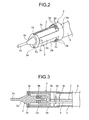
- FIG. 2 is a perspective view showing an ultrasonic generating unit, a supporting member, and a sheath which constitute the ultrasonic treatment apparatus shown in FIG. 1
- FIG. 3 is a cross-sectional view of the ultrasonic generating unit, the supporting member, and the sheath, taken in a lengthwise direction
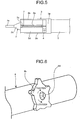
- FIG. 5 is a plan view of FIG. 2.
- the ultrasonic treatment apparatus 1 as shown in FIG. 1 includes an ultrasonic transducer unit 2, a supporting cover 3, a wiring 4, a sheath 5, and an operation wire 7.
- the ultrasonic transducer unit 2 which is disposed at the distal end of the ultrasonic treatment apparatus 1, as shown in FIGS. 1 to 5, includes a piezoelectric device 2b disposed at one end of a horn 2a, and a treatment unit 2c disposed at the other end.
- the rear of the horn 2a with the piezoelectric device 2b is surrounded by a cylinder 2d.
- the ultrasonic transducer unit 2 is provided with a wire groove 2e in a lengthwise direction on each of upper and lower sides of the cylinder 2d.
- the supporting cover 3, as shown in FIGS. 1 to 5, is attached to one end of the sheath 5.
- the supporting cover 3 as shown in FIG. 2 is provided with two supporting arms 3b which extend frontward from a cylindrical portion 3a and whose ends are each attached to the cylinder 2d with a supporting pin 3c.
- the cylindrical portion 3a is provided with two pairs of wire guides 3e, one being located at upper side and the other being located at lower side. Each of the wire guides 3e is supported by a pin 3d and serves in pairs as a roller to guide the operation wire 7.
- the supporting pin 3c is attached to the cylinder 2d at a position between two wire grooves 2e on the outer circumference of the cylinder 2d and at an ultrasonic vibration node. This allows suppressing the influence of the ultrasonic vibration to a minimum level, and the supporting cover 3 rotatably supports the ultrasonic transducer unit 2 about the supporting pin 3c.
- the pairs of wire guides 3e at upper and lower sides are located at a position shifted toward the supporting arm 3b side with respect to the extended direction of the wire groove 2e, as shown in FIG. 1.
- the supporting pin 3c may be attached through the horn 2a as shown in FIG. 4A, or may be replaced with two protrusions 2f at an ultrasonic vibration node of the horn 2a to support the ultrasonic transducer unit 2 with the supporting cover 3.
- a foot switch is provided between the wiring 4 and the power source to switch on/off the piezoelectric device 2b of the ultrasonic treatment apparatus 1.
- the sheath 5 is attached to the operation unit 6 at one end, and to the supporting cover 3 at the other end.
- the sheath 5 is fixed to the operation unit 6 and the supporting cover 3 with a laser welding or an adhesive material.
- the operation unit 6 to be gripped by an operator's hand to operate the ultrasonic treatment apparatus 1 is provided with the output port 6a for the wiring 4 near the connection part with the sheath 5, as shown in FIGS. 1 and 6.
- the operation unit 6 is provided with an operation dial 6b about midway of an outer surface of the operation unit 6, and a pulley 6c inside which is coaxial with the operation dial 6b. Turning the operation dial 6b clockwise or anti-clockwise shifts the operation wire 7 in the lengthwise direction and thus rotates the ultrasonic transducer unit 2 about the supporting pin 3c.
- the operation dial 6b includes a hand screw 6d which serves to hold the ultrasonic transducer unit 2 at a desired rotation position when fixed to the operation unit 6 (see FIG.
- the hand screw 6d When turned to one direction, the hand screw 6d is loosened to release the fixation of the operation dial 6b to the operation unit 6, thereby allowing the ultrasonic transducer unit 2 to freely rotate with respect to the supporting cover 3. When turned to the other direction, the hand screw 6d is tightened to fix to the operation unit 6, thereby holding the ultrasonic transducer unit 2 against the supporting cover 3 to prevent it from rotating.
- the operation unit 6 is further provided with guide rollers 6e at appropriate positions inside, for guiding a movement of the operation wire 7 in the lengthwise direction depending on the turning of the operation dial 6b.
- the operation wire 7 is laid inside the sheath 5 in the lengthwise direction, both ends being connected to the outside of the ultrasonic transducer unit 2 and its middle portion being wound around the pulley 6c. Both ends of the operation wire 7 are disposed in the wire grooves 2e formed on the cylinder 2d, and connected to the outside of the cylinder 2d with a wire pin 7a at an ultrasonic vibration node. This prevents the ultrasonic vibration generated in the ultrasonic transducer unit 2 from propagating to the operation wire 7, resulting in suppressing an energy loss of the ultrasonic transducer unit 2.
- the slack remover 8 serves to absorb the slack and tension of the operation wire 7 when the operation dial 6b is turned. Inside a case 8a, a locking unit 8b having a large-diameter is stored for locking the ends of the operation wire 7.
- the operation dial 6b in FIG. 1 is, for example, turned clockwise, the operation wire 7 laid at the upper side of the operation unit 6 is pulled by the pulley 6c and becomes strained, whereas the operation wire 7 laid at the lower side of the operation unit 6 becomes slack.
- the distal end of the treatment unit 2c faces obliquely upward and accordingly the rear part of the cylinder 2d falls down.
- the slack remover 8 absorbs the slack and tension of the operation wire 7 when the operation dial 6b is turned, to prevent the operation wire 7 from getting tangled and allow the ultrasonic transducer unit 2 to rotate smoothly.
- the ultrasonic treatment apparatus 1 having above described structure is, for example, used in an endoscope 10 shown in FIG. 8 as follows.
- the endoscope 10 includes an operation unit 11 and an insert part 16 which is inserted into a body cavity.
- the operation unit 11 includes an eyepiece unit 12, a main body of the operation unit 13 having a hollow spherical form, a grip unit 14, and a main body of joint 15.
- a venting cap 15a is attached to the main body of joint 15 at a slant for inserting the ultrasonic treatment apparatus 1, and communicated with a channel 15b inside of the main body of joint 15 as shown in FIGS. 8 and 9.
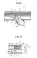
- the insert part 16 has a channel 16a formed inside (see FIG.
- the insert part 16 is provided with an observation window 16c and an objective lens 16d at the distal end of the insert part 16, allowing an observation of the inside body cavity via an image guide 16e.
- the ultrasonic transducer unit 2 of the ultrasonic treatment apparatus 1 is first inserted via the venting cap 15a as shown in FIG. 9.
- the endoscope 10 has a K branch structure where the venting cap 15a is inclined to the channel 15b, which requires the fixation of the operation dial 6b of the ultrasonic treatment apparatus 1 to be released by loosening the hand screw 6d, in advance of insertion into the venting cap 15a.
- the ultrasonic transducer unit 2 of the ultrasonic treatment apparatus 1 When the ultrasonic transducer unit 2 of the ultrasonic treatment apparatus 1 is inserted as shown in FIG. 9, the ultrasonic transducer unit 2 freely rotates about the supporting pin 3c with respect to the supporting cover 3 under a press force given from the operation unit 6.
- the ultrasonic treatment apparatus 1 is easily inserted into the channel 15b via the venting cap 15a as the ultrasonic transducer unit 2 rotates to adapt to the shapes of the inner wall of the venting cap 15a and the channel 15b.
- the ultrasonic treatment apparatus 1 is inserted into the channel 15b via the venting cap 15a provided to the main body of joint 15, and reaches the channel 16a of the insert part 16 as shown in FIG. 10. Then, the treatment device 2c is projected from the distal end of the insert part 16 of the endoscope 10 to find a diseased part by operating the operation unit 11 as observed through the eyepiece unit 12. When the diseased position is found, the ultrasonic transducer unit 2 is directed to the diseased part by turning the operation dial 6b, and then the operation dial 6b is fixed to the operation unit 6 by turning the handle screw 6d.
- the ultrasonic transducer unit 2 is fixed in the direction of the diseased part, thereby allowing further insertion of the ultrasonic treatment apparatus 1 into the endoscope 10, and an execution of ultrasonic treatment with the distal end of the treatment device 2c directly applied to the diseased part.
- the hand screw 6d is turned in the loosening direction to release the fixation of the operation dial 6b, and the ultrasonic treatment apparatus 1 is pulled out from the endoscope 10 by holding the operation unit 6.
- the fixation of the operation dial 6b is released in the ultrasonic treatment apparatus 1
- the ultrasonic transducer unit 2 freely rotates about the supporting pin 3c with respect to the supporting cover 3.
- the ultrasonic treatment apparatus 1 moves smoothly without being stuck due to an interference of the ultrasonic transducer unit 2 with the inner walls of channels 15b and 16a and the venting cap 15a when pulled out of the endoscope 10.
- the ultrasonic treatment apparatus 1 can be inserted and removed easily into and from the channels 15b and 16a of the endoscope 10.
- the ultrasonic treatment apparatus 1 is an oblique-viewing endoscope 20 as shown in FIG. 11 which has an inclined channel 21a at the distal end of the insert part 21 to be inserted into the body cavity, it is also easy to insert and remove the ultrasonic treatment apparatus 1.
- the end of the channel 21a into which the ultrasonic treatment apparatus 1 is inserted and the end of a channel 21b where an optical system is arranged are inclined upward.
- the channel 21b is, as shown in FIG. 11, provided with an observation window 21c, an observation optical system 21d, and an image pick-up device 21e located at an imaging position of the observation optical system 21d.
- the ultrasonic treatment apparatus 1 is inserted into the channel 21a of the oblique-viewing endoscope 20.
- the ultrasonic treatment apparatus 1 is inserted into the channel 21a as the ultrasonic transducer unit 2 supported by the supporting cover 3 rotates about the supporting pin 3c to move in accordance with the shape of the channel 21a.
- the ultrasonic treatment apparatus 1 easily goes through even around a part with obliquely upward slope at the end of the channel 21a as shown in FIG. 11. Accordingly, the treatment device 2c of the ultrasonic transducer unit 2 of the ultrasonic treatment apparatus 1 is projected from the end of the channel 21a as shown in FIG. 12.
- the diseased part is found by operating the oblique-viewing endoscope 20 as observed through the eyepiece unit, the operation dial 6b is turned to direct the ultrasonic transducer unit 2 to the diseased part, and the hand screw 6d is turned to fix the operation dial 6b.
- the ultrasonic transducer unit 2 is fixed in the direction of the diseased part, thereby allowing further insertion of the ultrasonic treatment apparatus 1 into the channel 21a, and an execution of ultrasonic treatment with the distal end of the treatment unit 2c directly applied to the diseased part.
- the hand screw 6d is loosened to release the fixation of the operation dial 6b, and the ultrasonic treatment apparatus 1 can be easily pulled out of the endoscope 20 by holding the operation unit 6.
- the ultrasonic transducer unit 2 is rotatably attached to the supporting cover 3.
- the ultrasonic treatment apparatus 1 can be inserted into and removed easily from the channel of the endoscope and have an advantage in usability.
- the ultrasonic transducer unit 2 of the ultrasonic treatment apparatus 1 is supported with the supporting cover 3 at an ultrasonic vibration node, thereby allowing suppressing an influence of the ultrasonic vibration on the supporting cover 3 to a minimum level, and an energy loss of the ultrasonic transducer unit 2 as little as possible.
- the ultrasonic treatment apparatus according to the present invention as described above is advantageous when inserted into and removing from a channel of an endoscope for ultrasonic treatment, specifically as an ultrasonic treatment apparatus used in an endoscope whose channel has a branch or a slant.
Landscapes
- Health & Medical Sciences (AREA)
- Surgery (AREA)
- Engineering & Computer Science (AREA)
- Life Sciences & Earth Sciences (AREA)
- Heart & Thoracic Surgery (AREA)
- Veterinary Medicine (AREA)
- Nuclear Medicine, Radiotherapy & Molecular Imaging (AREA)
- Biomedical Technology (AREA)
- Public Health (AREA)
- Medical Informatics (AREA)
- Molecular Biology (AREA)
- Animal Behavior & Ethology (AREA)
- General Health & Medical Sciences (AREA)
- Dentistry (AREA)
- Mechanical Engineering (AREA)
- Robotics (AREA)
- Ultra Sonic Daignosis Equipment (AREA)
- Surgical Instruments (AREA)
Abstract
Description
- The present invention relates to an ultrasonic treatment apparatus.
- Conventionally, an ultrasonic treatment apparatus has been used for giving ultrasonic treatment to a desired part such as a diseased part, being inserted into a channel via a venting cap of an endoscope with its distal end projected from the endoscope (see
Patent Document 1, for example). - Patent Document 1:
Japanese Patent Application Laid-Open No. H02-191423 - A conventional endoscope, as disclosed in
Patent Document 1, includes a channel formed inside a linear insert part to be inserted into a body cavity. The endoscope further includes a venting cap attached at a slant to a proximal part of the linear insert part for inserting an ultrasonic treatment apparatus into the channel, having a structure called "K branch" where the venting cap is inclined to the insert part, i.e., the channel. Besides, there is another endoscope having an inclined channel at the distal end of the insert part which is inserted into a body cavity (hereinafter referred to as an angled endoscope). Consequently, an ultrasonic treatment apparatus provided with an ultrasonic generating unit at the distal end thereof has difficulty in insertion and removal of the ultrasonic generating unit into and from the channel due to an interference with the inner wall of the channel at the K branch of the venting cap or the distal end part of the angled endoscope. Specifically, the difficulty becomes worse when the length of the ultrasonic generating unit is more than that of the venting cap. - In view of the foregoing, an object of the present invention is to provide an ultrasonic treatment apparatus which has excellent usability, with easiness in insertion and removal of an ultrasonic generating unit into and from a channel of an endoscope.
- To solve the above problems and to achieve the object, an ultrasonic treatment apparatus according to
claim 1 is for giving an ultrasonic treatment to a desired part in a body cavity with an ultrasonic generating unit projected from a distal end of an endoscope which is introduced-into the body cavity, and includes a supporting member which rotatably supports the ultrasonic generating unit at an ultrasonic vibration node; and an operation wire which operates to rotate the ultrasonic generating unit. - According to the ultrasonic treatment apparatus set forth as
claim 1, the ultrasonic generating unit is easily inserted into and removed from the channel of the endoscope, resulting in excellent usability. - In the ultrasonic treatment apparatus as set forth in
claim 2, the supporting member is attached to one end of a sheath which is provided with an operation unit at the other end. - In the ultrasonic treatment apparatus as set forth in
claim 3, the operation unit is provided with an operation dial for operating the operation wire. - In the ultrasonic treatment apparatus as set forth in
claim 4, the operation wire is laid inside the sheath, both ends being connected to an outside of the ultrasonic generating unit at the ultrasonic vibration node and a middle portion being wound around a winding member provided with the operation dial. - In the ultrasonic treatment apparatus as set forth in
claim 5, the operation dial includes a fixing unit which fixes an operation position and holds the ultrasonic generating unit at a desired position. - In the ultrasonic treatment apparatus according to the present invention, the ultrasonic generating unit rotates in accordance with a shape of the channel when inserted into the channel, thereby allowing easy insertion and removal of the ultrasonic generating unit into and from the channel, resulting in excellent usability.
-
- FIG. 1 is a front view of a partial cross-section of a schematic structure of an ultrasonic treatment apparatus;
- FIG. 2 is a perspective view showing an ultrasonic generating unit, a supporting member, and a sheath which constitute the ultrasonic treatment apparatus shown in FIG. 1;
- FIG. 3 is a cross-sectional view of the ultrasonic generating unit, the supporting member, and the sheath , taken in a lengthwise direction;
- FIG. 4A is a cross-sectional view of a first modification in which a supporting cover supports an ultrasonic transducer unit;
- FIG. 4B is a cross-sectional view of a second modification in which the supporting cover supports the ultrasonic transducer unit;
- FIG. 5 is a plan view of FIG. 2;
- FIG. 6 is a perspective view of an operation unit of the ultrasonic treatment apparatus shown in FIG. 1;
- FIG. 7 is a perspective view of the ultrasonic generating unit shown in FIG. 2 in a rotational state;
- FIG. 8 is a front view of one example of an endoscope into which the ultrasonic treatment apparatus shown in FIG. 1 is inserted;
- FIG. 9 is a cross-sectional view of the endoscope shown in FIG. 8 with the ultrasonic treatment apparatus shown in FIG. 1 inserted through a venting cap of the endoscope;
- FIG. 10 is a cross-sectional view of the endoscope shown in FIG. 8 with a treatment unit of the ultrasonic treatment apparatus shown in FIG. 1 projected from a distal end of the endoscope;
- FIG. 11 is a cross-sectional view of a relevant part of an oblique-viewing endoscope with the ultrasonic treatment apparatus shown in FIG. 1 inserted into a channel of the oblique-viewing endoscope; and
- FIG. 12 is a cross-sectional view of a relevant part of the oblique-viewing endoscope shown in FIG. 11 with the treatment unit of the ultrasonic treatment apparatus shown in FIG. 1 projected from the distal end of the channel of the oblique-viewing endoscope.
-
- 11
- Ultrasonic treatment apparatus
- 2
- Ultrasonic transducer unit
- 2a
- Horn
- 2b
- Piezoelectric device
- 2c
- Treatment unit
- 2d
- Cylinder
- 2e
- Wire groove
- 2f
- Protrusion
- 3
- Supporting cover
- 3a
- Cylindrical portion
- 3b
- Supporting arm
- 3c
- Supporting pin
- 4
- Wiring
- 5
- Sheath
- 6
- Operation unit
- 6a
- Output port
- 6b
- Operation dial
- 6c
- Pulley
- 6d
- Hand screw
- 7
- Operation wire
- 8
- Slack remover
- 7a
- Wire pin.
- 10
- Endoscope
- 11
- Operation unit
- 16
- Insert part
- 12
- Eyepiece unit
- 13
- Main body of operation unit
- 14
- Grip unit
- 15
- Main body of joint
- 15a
- Venting cap
- 15b
- Channel
- 16a
- Channel
- 16b
- Curved frame
- 16c
- Observation window
- 16d
- Objective lens
- 16e
- Image guide
- 20
- Oblique-viewing endoscope
- 21a, 21b
- Channels
- 21c
- Observation window
- 21d
- Observation optical system
- 21e
- Image pick-up device
- Exemplary embodiments of an ultrasonic treatment apparatus according to the present invention will be described in detail with reference to the accompanying drawings. FIG. 1 is a front view of a partial cross-section of a schematic structure of an ultrasonic treatment apparatus; FIG. 2 is a perspective view showing an ultrasonic generating unit, a supporting member, and a sheath which constitute the ultrasonic treatment apparatus shown in FIG. 1; FIG. 3 is a cross-sectional view of the ultrasonic generating unit, the supporting member, and the sheath, taken in a lengthwise direction; and FIG. 5 is a plan view of FIG. 2.
- The
ultrasonic treatment apparatus 1 as shown in FIG. 1 includes anultrasonic transducer unit 2, a supportingcover 3, awiring 4, asheath 5, and anoperation wire 7. - The
ultrasonic transducer unit 2, which is disposed at the distal end of theultrasonic treatment apparatus 1, as shown in FIGS. 1 to 5, includes apiezoelectric device 2b disposed at one end of ahorn 2a, and atreatment unit 2c disposed at the other end. The rear of thehorn 2a with thepiezoelectric device 2b is surrounded by acylinder 2d. Theultrasonic transducer unit 2 is provided with awire groove 2e in a lengthwise direction on each of upper and lower sides of thecylinder 2d. - The supporting
cover 3, as shown in FIGS. 1 to 5, is attached to one end of thesheath 5. The supportingcover 3 as shown in FIG. 2 is provided with two supportingarms 3b which extend frontward from acylindrical portion 3a and whose ends are each attached to thecylinder 2d with a supportingpin 3c. Thecylindrical portion 3a is provided with two pairs ofwire guides 3e, one being located at upper side and the other being located at lower side. Each of the wire guides 3e is supported by apin 3d and serves in pairs as a roller to guide theoperation wire 7. - The supporting
pin 3c is attached to thecylinder 2d at a position between twowire grooves 2e on the outer circumference of thecylinder 2d and at an ultrasonic vibration node. This allows suppressing the influence of the ultrasonic vibration to a minimum level, and the supportingcover 3 rotatably supports theultrasonic transducer unit 2 about the supportingpin 3c. The pairs ofwire guides 3e at upper and lower sides are located at a position shifted toward the supportingarm 3b side with respect to the extended direction of thewire groove 2e, as shown in FIG. 1. Thus, theultrasonic transducer unit 2 can effectively rotate under a tensile force of theoperation wire 7. The supportingpin 3c may be attached through thehorn 2a as shown in FIG. 4A, or may be replaced with twoprotrusions 2f at an ultrasonic vibration node of thehorn 2a to support theultrasonic transducer unit 2 with the supportingcover 3. - The
wiring 4, whose proximal portion extended from thecylinder 2d is disposed inside thesheath 5, is led to an output port 6a of theoperation unit 6 to feed electrical power from an external power source to thepiezoelectric device 2b, as shown in FIGS. 1 and 3. A foot switch is provided between thewiring 4 and the power source to switch on/off thepiezoelectric device 2b of theultrasonic treatment apparatus 1. - The
sheath 5 is attached to theoperation unit 6 at one end, and to the supportingcover 3 at the other end. Thesheath 5 is fixed to theoperation unit 6 and the supportingcover 3 with a laser welding or an adhesive material. - The
operation unit 6 to be gripped by an operator's hand to operate theultrasonic treatment apparatus 1 is provided with the output port 6a for thewiring 4 near the connection part with thesheath 5, as shown in FIGS. 1 and 6. As shown in FIG. 1, theoperation unit 6 is provided with anoperation dial 6b about midway of an outer surface of theoperation unit 6, and apulley 6c inside which is coaxial with theoperation dial 6b. Turning theoperation dial 6b clockwise or anti-clockwise shifts theoperation wire 7 in the lengthwise direction and thus rotates theultrasonic transducer unit 2 about the supportingpin 3c. Theoperation dial 6b includes ahand screw 6d which serves to hold theultrasonic transducer unit 2 at a desired rotation position when fixed to the operation unit 6 (see FIG. 6). When turned to one direction, thehand screw 6d is loosened to release the fixation of theoperation dial 6b to theoperation unit 6, thereby allowing theultrasonic transducer unit 2 to freely rotate with respect to the supportingcover 3. When turned to the other direction, thehand screw 6d is tightened to fix to theoperation unit 6, thereby holding theultrasonic transducer unit 2 against the supportingcover 3 to prevent it from rotating. Theoperation unit 6 is further provided withguide rollers 6e at appropriate positions inside, for guiding a movement of theoperation wire 7 in the lengthwise direction depending on the turning of theoperation dial 6b. - With a slack remover 8 provided near the
pulley 6c inside theoperation unit 6 as shown in FIG. 1, theoperation wire 7 is laid inside thesheath 5 in the lengthwise direction, both ends being connected to the outside of theultrasonic transducer unit 2 and its middle portion being wound around thepulley 6c. Both ends of theoperation wire 7 are disposed in thewire grooves 2e formed on thecylinder 2d, and connected to the outside of thecylinder 2d with awire pin 7a at an ultrasonic vibration node. This prevents the ultrasonic vibration generated in theultrasonic transducer unit 2 from propagating to theoperation wire 7, resulting in suppressing an energy loss of theultrasonic transducer unit 2. - The slack remover 8 serves to absorb the slack and tension of the
operation wire 7 when theoperation dial 6b is turned. Inside acase 8a, alocking unit 8b having a large-diameter is stored for locking the ends of theoperation wire 7. When theoperation dial 6b in FIG. 1 is, for example, turned clockwise, theoperation wire 7 laid at the upper side of theoperation unit 6 is pulled by thepulley 6c and becomes strained, whereas theoperation wire 7 laid at the lower side of theoperation unit 6 becomes slack. Hence, in theultrasonic transducer unit 2 in FIG. 7, compared with the state shown in FIG. 1, the distal end of thetreatment unit 2c faces obliquely upward and accordingly the rear part of thecylinder 2d falls down. The slack remover 8 absorbs the slack and tension of theoperation wire 7 when theoperation dial 6b is turned, to prevent theoperation wire 7 from getting tangled and allow theultrasonic transducer unit 2 to rotate smoothly. - The
ultrasonic treatment apparatus 1 having above described structure is, for example, used in anendoscope 10 shown in FIG. 8 as follows. Here, theendoscope 10 includes anoperation unit 11 and aninsert part 16 which is inserted into a body cavity. Theoperation unit 11 includes aneyepiece unit 12, a main body of theoperation unit 13 having a hollow spherical form, agrip unit 14, and a main body of joint 15. A ventingcap 15a is attached to the main body of joint 15 at a slant for inserting theultrasonic treatment apparatus 1, and communicated with achannel 15b inside of the main body of joint 15 as shown in FIGS. 8 and 9. Theinsert part 16 has achannel 16a formed inside (see FIG. 10) which is communicated with a channel formed in theoperation unit 11, and has a bendable structure with pluralcurved frames 16b which are coupled with each other as shown in FIG. 10. Theinsert part 16 is provided with anobservation window 16c and anobjective lens 16d at the distal end of theinsert part 16, allowing an observation of the inside body cavity via animage guide 16e. - The
ultrasonic transducer unit 2 of theultrasonic treatment apparatus 1 is first inserted via theventing cap 15a as shown in FIG. 9. Here, theendoscope 10 has a K branch structure where theventing cap 15a is inclined to thechannel 15b, which requires the fixation of theoperation dial 6b of theultrasonic treatment apparatus 1 to be released by loosening thehand screw 6d, in advance of insertion into theventing cap 15a. - When the
ultrasonic transducer unit 2 of theultrasonic treatment apparatus 1 is inserted as shown in FIG. 9, theultrasonic transducer unit 2 freely rotates about the supportingpin 3c with respect to the supportingcover 3 under a press force given from theoperation unit 6. Compared with a conventional ultrasonic treatment apparatus which does not allow the ultrasonic transducer unit to rotate, theultrasonic treatment apparatus 1 is easily inserted into thechannel 15b via theventing cap 15a as theultrasonic transducer unit 2 rotates to adapt to the shapes of the inner wall of theventing cap 15a and thechannel 15b. - The
ultrasonic treatment apparatus 1 is inserted into thechannel 15b via theventing cap 15a provided to the main body of joint 15, and reaches thechannel 16a of theinsert part 16 as shown in FIG. 10. Then, thetreatment device 2c is projected from the distal end of theinsert part 16 of theendoscope 10 to find a diseased part by operating theoperation unit 11 as observed through theeyepiece unit 12. When the diseased position is found, theultrasonic transducer unit 2 is directed to the diseased part by turning theoperation dial 6b, and then theoperation dial 6b is fixed to theoperation unit 6 by turning thehandle screw 6d. Thus, theultrasonic transducer unit 2 is fixed in the direction of the diseased part, thereby allowing further insertion of theultrasonic treatment apparatus 1 into theendoscope 10, and an execution of ultrasonic treatment with the distal end of thetreatment device 2c directly applied to the diseased part. - When the ultrasonic treatment is finished, the
hand screw 6d is turned in the loosening direction to release the fixation of theoperation dial 6b, and theultrasonic treatment apparatus 1 is pulled out from theendoscope 10 by holding theoperation unit 6. Here, since the fixation of theoperation dial 6b is released in theultrasonic treatment apparatus 1, theultrasonic transducer unit 2 freely rotates about the supportingpin 3c with respect to the supportingcover 3. Hence, theultrasonic treatment apparatus 1 moves smoothly without being stuck due to an interference of theultrasonic transducer unit 2 with the inner walls ofchannels venting cap 15a when pulled out of theendoscope 10. Theultrasonic treatment apparatus 1 can be inserted and removed easily into and from thechannels endoscope 10. - Moreover, when the
ultrasonic treatment apparatus 1 is an oblique-viewingendoscope 20 as shown in FIG. 11 which has aninclined channel 21a at the distal end of theinsert part 21 to be inserted into the body cavity, it is also easy to insert and remove theultrasonic treatment apparatus 1. As shown in FIG. 11, in the oblique-viewingendoscope 20, the end of thechannel 21a into which theultrasonic treatment apparatus 1 is inserted and the end of achannel 21b where an optical system is arranged are inclined upward. Thechannel 21b is, as shown in FIG. 11, provided with anobservation window 21c, an observationoptical system 21d, and an image pick-updevice 21e located at an imaging position of the observationoptical system 21d. - After the
hand screw 6d is loosened to release the fixation of theoperation dial 6b in advance as described, theultrasonic treatment apparatus 1 is inserted into thechannel 21a of the oblique-viewingendoscope 20. Theultrasonic treatment apparatus 1 is inserted into thechannel 21a as theultrasonic transducer unit 2 supported by the supportingcover 3 rotates about the supportingpin 3c to move in accordance with the shape of thechannel 21a. Then, theultrasonic treatment apparatus 1 easily goes through even around a part with obliquely upward slope at the end of thechannel 21a as shown in FIG. 11. Accordingly, thetreatment device 2c of theultrasonic transducer unit 2 of theultrasonic treatment apparatus 1 is projected from the end of thechannel 21a as shown in FIG. 12. - Under this condition, the diseased part is found by operating the oblique-viewing
endoscope 20 as observed through the eyepiece unit, theoperation dial 6b is turned to direct theultrasonic transducer unit 2 to the diseased part, and thehand screw 6d is turned to fix theoperation dial 6b. Thus, theultrasonic transducer unit 2 is fixed in the direction of the diseased part, thereby allowing further insertion of theultrasonic treatment apparatus 1 into thechannel 21a, and an execution of ultrasonic treatment with the distal end of thetreatment unit 2c directly applied to the diseased part. When the ultrasonic treatment is finished, thehand screw 6d is loosened to release the fixation of theoperation dial 6b, and theultrasonic treatment apparatus 1 can be easily pulled out of theendoscope 20 by holding theoperation unit 6. - In the
ultrasonic treatment apparatus 1 according to the present invention as described above, theultrasonic transducer unit 2 is rotatably attached to the supportingcover 3. As a result, theultrasonic treatment apparatus 1 can be inserted into and removed easily from the channel of the endoscope and have an advantage in usability. Moreover, theultrasonic transducer unit 2 of theultrasonic treatment apparatus 1 is supported with the supportingcover 3 at an ultrasonic vibration node, thereby allowing suppressing an influence of the ultrasonic vibration on the supportingcover 3 to a minimum level, and an energy loss of theultrasonic transducer unit 2 as little as possible. - The ultrasonic treatment apparatus according to the present invention as described above is advantageous when inserted into and removing from a channel of an endoscope for ultrasonic treatment, specifically as an ultrasonic treatment apparatus used in an endoscope whose channel has a branch or a slant.
Claims (5)
- An ultrasonic treatment apparatus for giving ultrasonic treatment to a desired part in a body cavity with an ultrasonic generating unit projected from a distal end of art endoscope introduced into the body cavity, comprising:a supporting member which rotatably supports the ultrasonic generating unit at an ultrasonic vibration node; andan operation wire which operates to rotate the ultrasonic generating unit.
- The ultrasonic treatment apparatus according to claim 1, wherein the supporting member is attached to one end of a sheath which is provided with an operation unit at the other end.
- The ultrasonic treatment apparatus according to claim 2, wherein the operation unit includes an operation dial for operating the operation wire.
- The ultrasonic treatment apparatus according to claim 3, wherein the operation wire is laid inside the sheath, both ends being connected to an outside of the ultrasonic generating unit at the ultrasonic vibration node and a middle portion being wound around a winding member provided with the operation dial.
- The ultrasonic treatment apparatus according to claim 3 or 4, wherein the operation dial includes a fixing unit which fixes an operation position and holds the ultrasonic generating unit at a desired position.
Applications Claiming Priority (2)
| Application Number | Priority Date | Filing Date | Title |
|---|---|---|---|
| JP2004122868A JP4578850B2 (en) | 2004-04-19 | 2004-04-19 | Ultrasonic treatment device |
| PCT/JP2004/016878 WO2005102198A1 (en) | 2004-04-19 | 2004-11-12 | Ultrasonic treatment tool |
Publications (2)
| Publication Number | Publication Date |
|---|---|
| EP1738704A1 true EP1738704A1 (en) | 2007-01-03 |
| EP1738704A4 EP1738704A4 (en) | 2010-12-29 |
Family
ID=35196698
Family Applications (1)
| Application Number | Title | Priority Date | Filing Date |
|---|---|---|---|
| EP04821908A Withdrawn EP1738704A4 (en) | 2004-04-19 | 2004-11-12 | ULTRASONIC TREATMENT TOOL |
Country Status (4)
| Country | Link |
|---|---|
| US (1) | US20060264787A1 (en) |
| EP (1) | EP1738704A4 (en) |
| JP (1) | JP4578850B2 (en) |
| WO (1) | WO2005102198A1 (en) |
Families Citing this family (5)
| Publication number | Priority date | Publication date | Assignee | Title |
|---|---|---|---|---|
| EP2014248B1 (en) * | 2007-07-13 | 2010-01-20 | Stryker Trauma GmbH | Ultrasonic handpiece |
| US8540748B2 (en) | 2008-07-07 | 2013-09-24 | Intuitive Surgical Operations, Inc. | Surgical instrument wrist |
| US20140005702A1 (en) * | 2012-06-29 | 2014-01-02 | Ethicon Endo-Surgery, Inc. | Ultrasonic surgical instruments with distally positioned transducers |
| US10226274B2 (en) | 2015-04-16 | 2019-03-12 | Ethicon Llc | Ultrasonic surgical instrument with articulation joint having plurality of locking positions |
| US10034683B2 (en) * | 2015-04-16 | 2018-07-31 | Ethicon Llc | Ultrasonic surgical instrument with rigidizing articulation drive members |
Family Cites Families (18)
| Publication number | Priority date | Publication date | Assignee | Title |
|---|---|---|---|---|
| JPS6388311U (en) * | 1986-11-28 | 1988-06-08 | ||
| US4893628A (en) * | 1988-04-04 | 1990-01-16 | Bjorn Angelsen | Dual element ultrasonic transducer probe for combined imaging of tissue structures and blood flow in real time |
| GB2226245A (en) * | 1988-11-18 | 1990-06-27 | Alan Crockard | Endoscope, remote actuator and aneurysm clip applicator. |
| US5409453A (en) * | 1992-08-12 | 1995-04-25 | Vidamed, Inc. | Steerable medical probe with stylets |
| JP3234032B2 (en) * | 1993-03-12 | 2001-12-04 | 株式会社東芝 | Ultrasonic probe |
| US5469852A (en) * | 1993-03-12 | 1995-11-28 | Kabushiki Kaisha Toshiba | Ultrasound diagnosis apparatus and probe therefor |
| JP3302144B2 (en) * | 1993-12-17 | 2002-07-15 | オリンパス光学工業株式会社 | Suture ligature device |
| US5471988A (en) * | 1993-12-24 | 1995-12-05 | Olympus Optical Co., Ltd. | Ultrasonic diagnosis and therapy system in which focusing point of therapeutic ultrasonic wave is locked at predetermined position within observation ultrasonic scanning range |
| AU702754B2 (en) * | 1994-02-23 | 1999-03-04 | Smith & Nephew, Inc. | Surgical instrument |
| JPH08117240A (en) * | 1994-10-20 | 1996-05-14 | Alps Electric Co Ltd | Treatment equipment |
| US5695491A (en) * | 1994-11-22 | 1997-12-09 | Washington Research Foundation | Endoscopic accessory and containment system |
| US5762067A (en) * | 1996-05-30 | 1998-06-09 | Advanced Technology Laboratories, Inc. | Ultrasonic endoscopic probe |
| US5662116A (en) * | 1995-09-12 | 1997-09-02 | Fuji Photo Optical Co., Ltd. | Multi-plane electronic scan ultrasound probe |
| US6416525B1 (en) * | 1999-06-08 | 2002-07-09 | Olympus Optical Co., Ltd. | Ultrasonic vibrator capable of infallably preventing drops of water from entering the inside of a casing of the vibrator even if autoclave sterilization without a drying process is performed |
| JP4422243B2 (en) * | 1999-09-01 | 2010-02-24 | オリンパス株式会社 | Ultrasonic treatment device |
| US7473224B2 (en) * | 2001-05-29 | 2009-01-06 | Ethicon Endo-Surgery, Inc. | Deployable ultrasound medical transducers |
| JP3990189B2 (en) * | 2002-05-21 | 2007-10-10 | アロカ株式会社 | Ultrasonic probe and its operation device |
| JP2004000336A (en) * | 2002-05-31 | 2004-01-08 | Olympus Corp | Ultrasonic treatment apparatus |
-
2004
- 2004-04-19 JP JP2004122868A patent/JP4578850B2/en not_active Expired - Fee Related
- 2004-11-12 WO PCT/JP2004/016878 patent/WO2005102198A1/en not_active Ceased
- 2004-11-12 EP EP04821908A patent/EP1738704A4/en not_active Withdrawn
-
2006
- 2006-07-07 US US11/482,399 patent/US20060264787A1/en not_active Abandoned
Also Published As
| Publication number | Publication date |
|---|---|
| WO2005102198A1 (en) | 2005-11-03 |
| JP4578850B2 (en) | 2010-11-10 |
| US20060264787A1 (en) | 2006-11-23 |
| JP2005304606A (en) | 2005-11-04 |
| EP1738704A4 (en) | 2010-12-29 |
Similar Documents
| Publication | Publication Date | Title |
|---|---|---|
| KR102379863B1 (en) | Endoscope module and modular endoscope device comprising thereof | |
| JP6099853B1 (en) | Endoscope | |
| JP3894092B2 (en) | Ultrasound endoscope | |
| JP7248701B2 (en) | Endoscope bending section and endoscope | |
| JP2002065589A (en) | Endoscope device | |
| JP6010268B1 (en) | Endoscope bending and endoscope | |
| JP6214464B2 (en) | Endoscope system | |
| WO2020003594A1 (en) | Wire fixing structure and endoscope | |
| US20060264787A1 (en) | Ultrasonic treatment apparatus | |
| WO2019225102A1 (en) | Tip cover device | |
| JP5445953B2 (en) | Yarn pulling propulsion endoscope device | |
| WO2019181042A1 (en) | Endoscope insertion aid, endoscope system | |
| JPH10276965A (en) | Endoscope | |
| JPH0723900A (en) | Endoscope | |
| JP2009189399A (en) | Endoscope stylet | |
| JP4365865B2 (en) | Insertion device | |
| JP3725849B2 (en) | Endoscope | |
| JP3806546B2 (en) | Endoscope | |
| JP2002325723A (en) | Endoscope device | |
| JP4338484B2 (en) | Endoscopic high-frequency incision tool | |
| KR101620831B1 (en) | Surgical instrument | |
| JP4127794B2 (en) | Endoscope | |
| JP5242041B2 (en) | Endoscope | |
| JP2004209267A (en) | Endoscope, and hardness adjusting device used for the same | |
| WO2019181039A1 (en) | Endoscope system and guide member |
Legal Events
| Date | Code | Title | Description |
|---|---|---|---|
| PUAI | Public reference made under article 153(3) epc to a published international application that has entered the european phase |
Free format text: ORIGINAL CODE: 0009012 |
|
| 17P | Request for examination filed |
Effective date: 20061017 |
|
| AK | Designated contracting states |
Kind code of ref document: A1 Designated state(s): DE FR GB |
|
| RIN1 | Information on inventor provided before grant (corrected) |
Inventor name: YAMADA, NORIHIRO Inventor name: SUZUKI, KEITA Inventor name: NAKAMURA, TAKEAKI |
|
| DAX | Request for extension of the european patent (deleted) | ||
| RBV | Designated contracting states (corrected) |
Designated state(s): DE FR GB |
|
| A4 | Supplementary search report drawn up and despatched |
Effective date: 20101130 |
|
| 17Q | First examination report despatched |
Effective date: 20110909 |
|
| STAA | Information on the status of an ep patent application or granted ep patent |
Free format text: STATUS: THE APPLICATION IS DEEMED TO BE WITHDRAWN |
|
| 18D | Application deemed to be withdrawn |
Effective date: 20120120 |