EP1738154B1 - Light delivery control system and method - Google Patents
Light delivery control system and method Download PDFInfo
- Publication number
- EP1738154B1 EP1738154B1 EP05732624.1A EP05732624A EP1738154B1 EP 1738154 B1 EP1738154 B1 EP 1738154B1 EP 05732624 A EP05732624 A EP 05732624A EP 1738154 B1 EP1738154 B1 EP 1738154B1
- Authority
- EP
- European Patent Office
- Prior art keywords
- light
- waveguide
- controlling
- irradiance profile
- control system
- Prior art date
- Legal status (The legal status is an assumption and is not a legal conclusion. Google has not performed a legal analysis and makes no representation as to the accuracy of the status listed.)
- Ceased
Links
Images



Classifications
-
- G—PHYSICS
- G01—MEASURING; TESTING
- G01N—INVESTIGATING OR ANALYSING MATERIALS BY DETERMINING THEIR CHEMICAL OR PHYSICAL PROPERTIES
- G01N21/00—Investigating or analysing materials by the use of optical means, i.e. using sub-millimetre waves, infrared, visible or ultraviolet light
-
- G—PHYSICS
- G06—COMPUTING OR CALCULATING; COUNTING
- G06F—ELECTRIC DIGITAL DATA PROCESSING
- G06F30/00—Computer-aided design [CAD]
- G06F30/30—Circuit design
-
- G—PHYSICS
- G02—OPTICS
- G02B—OPTICAL ELEMENTS, SYSTEMS OR APPARATUS
- G02B6/00—Light guides; Structural details of arrangements comprising light guides and other optical elements, e.g. couplings
- G02B6/0001—Light guides; Structural details of arrangements comprising light guides and other optical elements, e.g. couplings specially adapted for lighting devices or systems
- G02B6/0005—Light guides; Structural details of arrangements comprising light guides and other optical elements, e.g. couplings specially adapted for lighting devices or systems the light guides being of the fibre type
- G02B6/001—Light guides; Structural details of arrangements comprising light guides and other optical elements, e.g. couplings specially adapted for lighting devices or systems the light guides being of the fibre type the light being emitted along at least a portion of the lateral surface of the fibre
-
- G—PHYSICS
- G01—MEASURING; TESTING
- G01N—INVESTIGATING OR ANALYSING MATERIALS BY DETERMINING THEIR CHEMICAL OR PHYSICAL PROPERTIES
- G01N2201/00—Features of devices classified in G01N21/00
- G01N2201/08—Optical fibres; light guides
- G01N2201/0826—Fibre array at source, distributing
-
- G—PHYSICS
- G02—OPTICS
- G02B—OPTICAL ELEMENTS, SYSTEMS OR APPARATUS
- G02B6/00—Light guides; Structural details of arrangements comprising light guides and other optical elements, e.g. couplings
- G02B6/10—Light guides; Structural details of arrangements comprising light guides and other optical elements, e.g. couplings of the optical waveguide type
- G02B6/14—Mode converters
Definitions
- the present invention relates to controlling light delivery to improve uniformity and/or an irradiance profile of delivered light.
- Duct structures and other items allowing fluid flow may have photocatalyst material disposed on the surface to be activated by light from a light delivery system.
- the efficiency of the photoreactor depends in part on the uniformity of the light illuminating the item as well as the correspondence between the fluid flow profile and an irradiation profile of the light generated by the light delivery system.
- the geometric differences between the shape of the light source and the shape of the surface being illuminated may naturally cause some surfaces to receive more light than other surfaces (e.g., surfaces closer to the light source will have more illumination than surfaces farther from the light source).
- the system ideally matches the irradiation profile to the fluid flow profile.
- a non-uniform irradiance profile and/or a lack of a match between the irradiation profile and the fluid flow profile may result in less than optimum utilization of light energy. Areas experiencing excess fluid flow with respect to the irradiance profile, for example, will have excess target chemical species without sufficient photons in the emitted light to catalyze them. Similarly, areas experiencing low fluid flow will have fewer target chemical species than photons in the emitted light, thus wasting photons. This sub-optimal reactor efficiency occurs regardless of the specific method used to guide photons from the light source (e.g., free-space delivery, total internal reflection, etc.).
- US 2003/0026585 discloses a photoreactor that includes a photocatalyst, a light source and a light-redirecting means.
- US 4816145 and US 4204956 disclose systems for treating water comprising a light source and a flow meter.
- the present invention provides a system as in claim 1 and a method as in claim 19.
- the invention is directed to a system and method that controls light delivery to an object using a light distributor that redistributes light from a light source.
- This light distributor can be actively controlled by electronic circuitry or a microprocessor.
- the light distributor may redistribute light to make an irradiance profile of the light more uniform or, if the light source is in a photoreactor, to make the irradiance profile match a fluid flow profile in the reactor and/or generate light having a uniform irradiation profile.
- the irradiance profile may be controlled by modifying light leakage from a plurality of waveguides.
- the light leakage characteristics of a given waveguide may be modified by changing the radius of curvature of the waveguide, changing the cross-sectional dimension of the waveguide, changing the refractive index of a cladding on the waveguide, altering a surface roughness of the waveguide, and/or varying the density and/or size of scattering centers in the waveguide.
- the irradiance profile may be controlled by changing the light-directing properties of reflectors and/or lenses.
- the controller may, for example, change the orientation or shape of one or more reflectors or lenses.
- the invention can advantageously redirect light to areas that are far enough from the light source to experience reduced amounts of light, making the light distribution, and therefore the irradiance profile reflecting the distribution, more uniform over a desired space. Further, the invention can also control light based on received fluid flow data to match the irradiance profile to the fluid flow, increasing reactor efficiency.
- FIG. 1 is a representative diagram of a photoreactor 100 that can incorporate various preferred embodiments of the invention.
- the photoreactor 100 is used to, for example, catalyze a photocatalytic surface coating 102 on an HVAC duct or other substrate 104, such as a honeycomb structure.
- the photocatalytic surface coating 102 catalyzes the desired chemical reactions when a light distributor 106 distributes light from a light source 107, thus illuminating the coating with light energy (e.g., visible light, UV light, etc.) in the presence of the target chemical species within the photoreactor 100.
- the light distributor 106 and light source 107 can be completely separate from each other or can be integrated together into a single component.
- a fluid flow sensor 110 is disposed in the photoreactor 100 to monitor the flow of fluid (e.g., air or other fluid that contains chemicals to be reacted in the photoreactor) and one or more light sensors 112 that monitor the irradiation profile of the light energy from the light source 107. The data from the sensors 110, 112 may then be sent to a processor 114 for analysis.
- the fluid flow sensor 110 can be any device or devices that directly measure fluid flow.
- the fluid flow sensor 110 can be any device or combination of measurement devices that measure reactor operating conditions (e.g., duct damper positions, air speed, etc) from which the fluid flow can be estimated or inferred.
- the sensors 110, 112 may be eliminated if the fluid flow profile is already known or can be adequately estimated based on the operating conditions and characteristics of the system 100.
- the light distributor 106 may have characteristics that passively redistribute light to make the irradiance profile of the light reaching the photocatalyst 102 uniform and/or to match the irradiation profile with the fluid flow profile.
- the contaminant profile i.e., the profile of the chemical species to be reacted
- the contaminant profile is proportional to the fluid flow profile. This is because, in most cases, the contaminant concentration within the fluid will be constant within different areas of the fluid.
- the amount of contaminants flowing past a given point in the photoreactor will be proportional to the volume of fluid flowing past that point.
- the processor 114 may also output signals to a controller 116 that actively controls the light distributor 106 to redistribute light based on the data received from the processor 114 to change the irradiance profile of the light radiating on the photocatalyst 102, if needed.
- This embodiment allows active, dynamic control over the distributing properties of the light distributor 106.
- the remaining figures and the descriptions below describe different structures for the light distributor 106 and the different ways that the light distributor 106 makes the irradiance profile more uniform and/or to match the irradiance profile with the fluid flow profile.
- the invention is directed to a light distributor 106 that changes the irradiance profile of light reaching the photocatalyst 102.
- the light distributor 106 can have various structures. In the examples described below, Figures 2 through 6 show embodiments where the light distributor 106 is one or more waveguides, Figure 7 shows an embodiment where the light distributor 106 is one or more reflectors, and Figure 8 shows an embodiment where the light distributor 106 is one or more lenses.
- FIG. 2 is a representative diagram of a top view of one embodiment of the light distribution system according to the present invention.
- a plurality of optical waveguides 150 act as the light distributor to control light delivery from the light source 107 to the photocatalyst 102.
- the light leakage from the waveguide 150 is a function of the angle of incidence of the light beam at an interface between a core 151 of the waveguide and its cladding 154 as well as the incident irradiance of the light beam.
- a more detailed example of the core 151 and cladding 154 configuration is illustrated in Figure 4 for reference.
- the irradiance profile may be highest at locations closest to the light source 107.
- the curvature of the waveguides 150 can be varied to change the light leakage characteristics of the waveguide to increase the light leakage at areas that are further away from the light source 107.
- the waveguides 150 are curled to change the angle at which light in the waveguide strikes the core/cladding interface and provide a selected amount of light leakage from the waveguide. Areas that are further away from the light source 107 may be bent to have a smaller radius of curvature r to allow greater light leakage. This will balance the irradiance profile and achieve a uniform leakage irradiance over the entire photocatalyst 102.
- the radius of curvature r of the waveguides 150 may be decreased in areas where the fluid flow sensor 110 detects a higher fluid flow on the photocatalytic surface, thereby generating additional photons to catalyze the extra target chemical species in the photocatalyst 102.
- the curvature r can be formed during manufacture of the system 100 so that the light distributor 106 formed by the waveguides 150 can passively control light distribution.
- the radius of curvature of the waveguide 150 can be dynamically controlled so that light delivery can be varied as the detected fluid flow profile varies.
- the waveguides 150 themselves can have any shape and composition including, but not limited to, plates, cylinders (e.g., optical fibers) and foamed material.
- the shape of each waveguide 150 will influence the specific structure used to change the radius of curvature of the waveguide 150 to change the amount of light leakage from the waveguide 150 at selected areas in the reactor 100.
- the radius of curvature of each waveguide 150 can be selected during manufacture, thereby allowing the resulting light distributor 106 to passively redistribute light.
- the ends of the waveguides 150 may be connected to one or more actuators 152 that can twist the waveguides 150 to make their radius of curvatures tighter or looser.
- the actuators 152 are controlled by the controller 116 based on the desired irradiance profile.
- Figure 3 illustrates another embodiment of the invention.
- a cross-sectional dimension of the waveguide 150 can be varied to control light delivery to the item for making the irradiance profile uniform and/or for matching the irradiance profile with the fluid flow profile. Decreasing the cross-sectional area of a waveguide in, for example, a direction substantially perpendicular to a light propagation direction increases light leakage from the waveguide. Thus, waveguides in areas where the irradiance profile is low relative to other areas, and/or areas experiencing high fluid flow profiles may have their cross-sectional areas reduced to increase light leakage, and therefore increase the number of photons, in those areas.
- the variations in this embodiment can be conducted either during manufacturing to form a static waveguide 150 or during operation of the system itself as a dynamic waveguide 150.
- Devices used to decrease the cross-sectional area of the waveguide 150 may include, for example, devices that stretch and/or twist the waveguide (e.g., if the waveguide is made of a resilient material).
- the waveguides 150 may be made of a resilient material and have fixed ends.
- At least one waveguide 150 is connected to actuators 152 that can move to stretch or release the waveguide 150 and thereby reduce or increase its cross-sectional area, respectively.
- the actuators 152 are controlled by the controller 116 so that the amount of stretching or releasing corresponds to the desired irradiance profile.
- the actuators 152 can move in any manner and in any direction that will facilitate stretching and releasing.
- the actuators 152 are in the form of pins that are operated from above the pins to stretch or release the waveguide 150 in a given area.
- the cross-sectional area can be changed by changing a distance, and therefore an air gap, between the two plates.
- matching the irradiance profile with the fluid flow profile can be conducted either as a single setting or as a dynamic process that changes as the fluid flow profile changes.
- Figure 4 illustrates yet another embodiment of the invention. Rather than changing the curvature or the cross-sectional area of the waveguides 150, this embodiment changes the refractive index of the waveguide cladding 154.
- light leakage from the waveguide 150 is a function of the relative refractive indices of the core 151 of the waveguide 150 and its cladding 154.
- the core 151 generally has a higher refractive index, to varying degrees, than the cladding 154.
- the refractive index of the cladding 154 By modifying the refractive index of the cladding 154 to a value closer to the refractive index of the core 151, the decrease in the difference between the two refractive indices increases the light leakage from the core 151 through the cladding 154. This modification can be conducted during waveguide manufacture to form the static light distributor 106.
- the cladding 154 of the waveguide 150 comprises a birefringent material whose light propagation characteristics can change based on characteristics of an electric or magnetic field 158 generated near the waveguide 150 by a field generator, which acts as the actuator 152.
- the controller 116 can therefore change the refractive index of the cladding 154 by modulating the characteristics of the field.
- increasing the refractive index of the cladding 154 can be used to increase the percentage of incident light leakage in areas where the irradiance profile is lower and/or areas where the fluid flow is highest on the photocatalytic surface.
- the refractive index can also be altered by other influences, such as temperature, pressure, or mechanical strain.
- Figure 5 illustrates yet another embodiment of the invention.
- the embodiment shown in Figure 5 focuses on altering surface roughness, which in essence is altering local variations in curvature, in the waveguide 150 to control light leakage.
- altering surface roughness which in essence is altering local variations in curvature
- increasing the density and decreasing the size of local variations in the surface roughness of the waveguide may increase light leakage.
- certain waveguides 150 are selected for modification in surface roughness based on, for example, whether their irradiation profile needs to be increased to compensate for the higher profile closer to the light source 107 or whether the fluid flow profile is greater at a given area, thereby requiring increased light leakage in that area to optimize reactor efficiency.
- roughened areas 160 on the waveguide surface may be disposed at selected areas during waveguide manufacture to change the light leakage in those areas.
- the surface roughness can be controlled during waveguide manufacture by, for example, sandblasting or adding lumps of material to selected areas of the waveguide 150.
- the waveguide 150 may contain core material only, with no cladding, to provide greater control over the light leakage characteristics during manufacture to form a static light distributor 106.
- Figure 6 illustrates a further embodiment of the invention.
- the waveguide 150 has scattering centers 202 that affect light leakage from the waveguide 150 by scattering light out of the waveguide 150.
- the waveguide 150 in this example is illustrated to have a plate-like shape; however, this embodiment can be applied to waveguides of any shape.
- the local scattering centers 202 can be, for example, hollow regions (e.g., bubbles) or solid particles distributed within the waveguide material, with each scattering center comprising one bubble or particle that scatters light.
- the regions and/or particles that create the scattering centers can have any shape and size (e.g., regular, irregular, macroscopic, microscopic, etc.), depending on the desired light leakage effect.
- the actuator 152 can vary the density and size of the scattering centers 202 in the waveguide as well as completely create and eliminate scattering centers 202. For example, increasing the density of the scattering centers 202 in areas away from the light source 107 will help compensate for any reduced internal irradiation, thereby achieving more uniform light delivery to the photocatalytic surface of the item 104.
- scattering centers 202 may be formed during waveguide manufacture for a static light distributor 106.
- the waveguide 150 may include one or more scattering centers formed of particles 202 that exhibit precipitation characteristics where the particles precipitate and dissolve back into the waveguide material 150 depending on the temperature of the environment. Local areas of phase change materials that respond to temperature changes can also act as temperature-controlled scattering centers similar to the precipitation particles.
- the controller 116 can therefore modify the irradiance profile by changing the temperature in different areas of the waveguide 150.
- the waveguide 150 may include particles 202 of liquid crystal material whose light transmission characteristics are controlled by an orientation and/or strength of an electric field. Thus, the controller 116 can change the light leakage characteristics of the scattering centers by changing the electric field, thereby changing the orientation of the liquid crystal particles 202.
- the waveguides 150 can have any shape and are not limited to the cylindrical shapes as shown.
- the waveguides can be formed as straight or curved cylinders, plates, optical foam, or fibers having a circular, curved or polygonal cross-section.
- Figure 7 illustrates a side view of yet another embodiment of the invention applicable to systems where the light is not guided by total internal reflection like the waveguide examples described above.
- the irradiance profile is controlled by one or more reflectors 210 near the light source 107.
- the reflectors 210 can be shaped to achieve a uniform irradiance profile and/or match the fluid flow profile.
- the reflector 210 is made of a resilient reflective material that can be bent and reshaped based on the detected fluid flow profile so that the reflector 210 causes the irradiance profile to match the fluid flow profile.
- the controller 116 can reorient selected reflectors 210 to reflect light from the light source 107 in different directions at any given time using known adaptive optics techniques.
- Figure 8 illustrates a side view of another embodiment of the invention applicable to systems that do not use total internal reflection to guide light.
- one or more lenses 220 are used to guide light from the light source 107 to the photocatalytic surface.
- the shape and/or orientation of the lenses 220 can modify the irradiance profile to improve uniformity and/or match a fluid flow profile.
- the orientation of the lenses 220 can be controlled by the controller 116 based on the desired irradiance profile.
- lenses 220 and reflectors 210 can be used together in the same reactor 100 to provide greater control over the irradiance profile.
- the inventive system can be used to match an irradiance profile with a fluid flow profile either statically (where the irradiance profile reflects the fluid flow profile at a selected point in time) or dynamically (where the irradiance profile changes as the fluid flow changes) and can also be used to compensate for lower irradiance profile values in areas of the reactor 100 away from the light source 107.
Landscapes
- Physics & Mathematics (AREA)
- Engineering & Computer Science (AREA)
- General Physics & Mathematics (AREA)
- Computer Hardware Design (AREA)
- Theoretical Computer Science (AREA)
- Optics & Photonics (AREA)
- Evolutionary Computation (AREA)
- Geometry (AREA)
- General Engineering & Computer Science (AREA)
- Life Sciences & Earth Sciences (AREA)
- Health & Medical Sciences (AREA)
- Chemical & Material Sciences (AREA)
- Analytical Chemistry (AREA)
- Biochemistry (AREA)
- General Health & Medical Sciences (AREA)
- Immunology (AREA)
- Pathology (AREA)
- Physical Or Chemical Processes And Apparatus (AREA)
- Catalysts (AREA)
- Light Guides In General And Applications Therefor (AREA)
- Optical Couplings Of Light Guides (AREA)
- Mechanical Light Control Or Optical Switches (AREA)
Description
- The present invention relates to controlling light delivery to improve uniformity and/or an irradiance profile of delivered light.
- Duct structures and other items allowing fluid flow may have photocatalyst material disposed on the surface to be activated by light from a light delivery system. The efficiency of the photoreactor depends in part on the uniformity of the light illuminating the item as well as the correspondence between the fluid flow profile and an irradiation profile of the light generated by the light delivery system. However, the geometric differences between the shape of the light source and the shape of the surface being illuminated may naturally cause some surfaces to receive more light than other surfaces (e.g., surfaces closer to the light source will have more illumination than surfaces farther from the light source).
- Further, the system ideally matches the irradiation profile to the fluid flow profile. A non-uniform irradiance profile and/or a lack of a match between the irradiation profile and the fluid flow profile may result in less than optimum utilization of light energy. Areas experiencing excess fluid flow with respect to the irradiance profile, for example, will have excess target chemical species without sufficient photons in the emitted light to catalyze them. Similarly, areas experiencing low fluid flow will have fewer target chemical species than photons in the emitted light, thus wasting photons. This sub-optimal reactor efficiency occurs regardless of the specific method used to guide photons from the light source (e.g., free-space delivery, total internal reflection, etc.).
- There is a desire for a light delivery system and method that can improve the efficiency of photoreactors.
-
US 2003/0026585 discloses a photoreactor that includes a photocatalyst, a light source and a light-redirecting means.US 4816145 andUS 4204956 disclose systems for treating water comprising a light source and a flow meter. - The present invention provides a system as in claim 1 and a method as in claim 19. Thus, the invention is directed to a system and method that controls light delivery to an object using a light distributor that redistributes light from a light source. This light distributor can be actively controlled by electronic circuitry or a microprocessor. The light distributor may redistribute light to make an irradiance profile of the light more uniform or, if the light source is in a photoreactor, to make the irradiance profile match a fluid flow profile in the reactor and/or generate light having a uniform irradiation profile.
- In one embodiment, the irradiance profile may be controlled by modifying light leakage from a plurality of waveguides. The light leakage characteristics of a given waveguide may be modified by changing the radius of curvature of the waveguide, changing the cross-sectional dimension of the waveguide, changing the refractive index of a cladding on the waveguide, altering a surface roughness of the waveguide, and/or varying the density and/or size of scattering centers in the waveguide.
- In another embodiment, the irradiance profile may be controlled by changing the light-directing properties of reflectors and/or lenses. The controller may, for example, change the orientation or shape of one or more reflectors or lenses.
- Regardless of the specific way in which light is controlled, the invention can advantageously redirect light to areas that are far enough from the light source to experience reduced amounts of light, making the light distribution, and therefore the irradiance profile reflecting the distribution, more uniform over a desired space. Further, the invention can also control light based on received fluid flow data to match the irradiance profile to the fluid flow, increasing reactor efficiency.
- Certain preferred embodiments will now be described by way of example only and with reference to the accompanying drawings, in which:
-
Figure 1 is a representative diagram of a side view of a photoreactor incorporating the invention; -
Figure 2 is a representative diagram of a top view of a preferred embodiment of the invention; -
Figure 3 is a representative diagram of another preferred embodiment of the invention; -
Figure 4 is a representative diagram of a further preferred embodiment of the invention; -
Figure 5 is a representative diagram of yet another preferred embodiment of the invention; -
Figure 6 is a representative diagram of another preferred embodiment of the invention; -
Figure 7 is a representative diagram of further preferred embodiment of the invention; and -
Figure 8 is a representative diagram of yet another preferred embodiment of the invention. -
Figure 1 is a representative diagram of aphotoreactor 100 that can incorporate various preferred embodiments of the invention. Thephotoreactor 100 is used to, for example,
catalyze aphotocatalytic surface coating 102 on an HVAC duct orother substrate 104, such as a honeycomb structure. Thephotocatalytic surface coating 102 catalyzes the desired chemical reactions when alight distributor 106 distributes light from alight source 107, thus illuminating the coating with light energy (e.g., visible light, UV light, etc.) in the presence of the target chemical species within thephotoreactor 100. Thelight distributor 106 andlight source 107 can be completely separate from each other or can be integrated together into a single component. - In one embodiment, a
fluid flow sensor 110 is disposed in thephotoreactor 100 to monitor the flow of fluid (e.g., air or other fluid that contains chemicals to be reacted in the photoreactor) and one ormore light sensors 112 that monitor the irradiation profile of the light energy from thelight source 107. The data from thesensors fluid flow sensor 110 can be any device or devices that directly measure fluid flow. Alternatively, thefluid flow sensor 110 can be any device or combination of measurement devices that measure reactor operating conditions (e.g., duct damper positions, air speed, etc) from which the fluid flow can be estimated or inferred. - In an alternative example not part of the invention, the
sensors system 100. Thelight distributor 106 may have characteristics that passively redistribute light to make the irradiance profile of the light reaching thephotocatalyst 102 uniform and/or to match the irradiation profile with the fluid flow profile. In matching the irradiation profile with the fluid flow profile, it may be assumed that the contaminant profile (i.e., the profile of the chemical species to be reacted) is proportional to the fluid flow profile. This is because, in most cases, the contaminant concentration within the fluid will be constant within different areas of the fluid. Thus, the amount of contaminants flowing past a given point in the photoreactor will be proportional to the volume of fluid flowing past that point. - In one embodiment, based on the information from the
sensors controller 116 that actively controls thelight distributor 106 to redistribute light based on the data received from the processor 114 to change the irradiance profile of the light radiating on thephotocatalyst 102, if needed. This embodiment allows active, dynamic control over the distributing properties of thelight distributor 106. - The remaining figures and the descriptions below describe different structures for the
light distributor 106 and the different ways that thelight distributor 106 makes the irradiance profile more uniform and/or to match the irradiance profile with the fluid flow profile. The invention is directed to alight distributor 106 that changes the irradiance profile of light reaching thephotocatalyst 102. Thelight distributor 106 can have various structures. In the examples described below,Figures 2 through 6 show embodiments where thelight distributor 106 is one or more waveguides,Figure 7 shows an embodiment where thelight distributor 106 is one or more reflectors, andFigure 8 shows an embodiment where thelight distributor 106 is one or more lenses. -
Figure 2 is a representative diagram of a top view of one embodiment of the light distribution system according to the present invention. As is known in the art, optical waveguides operate on the principle of total internal reflection, where a critical angle Θc at which incident light will be reflected internally in the waveguide is defined Θc = arcsin (N2/N1), where N1 is the refractive index of the waveguide core and N2 is the refractive index of the waveguide cladding. Changing the angle at which incident light strikes the core/cladding interface is one method of controlling the amount of light reflected in and leaking out of the waveguide. - In this embodiment, a plurality of
optical waveguides 150 act as the light distributor to control light delivery from thelight source 107 to thephotocatalyst 102. For total internal reflection waveguides, such as photocatalyst-coated glass, for example, the light leakage from thewaveguide 150 is a function of the angle of incidence of the light beam at an interface between acore 151 of the waveguide and itscladding 154 as well as the incident irradiance of the light beam. A more detailed example of thecore 151 and cladding 154 configuration is illustrated inFigure 4 for reference. - In some cases, the irradiance profile may be highest at locations closest to the
light source 107. To make the irradiance profile in thereactor 100 more uniform, the curvature of thewaveguides 150 can be varied to change the light leakage characteristics of the waveguide to increase the light leakage at areas that are further away from thelight source 107. In the illustrated embodiment, thewaveguides 150 are curled to change the angle at which light in the waveguide strikes the core/cladding interface and provide a selected amount of light leakage from the waveguide. Areas that are further away from thelight source 107 may be bent to have a smaller radius of curvature r to allow greater light leakage. This will balance the irradiance profile and achieve a uniform leakage irradiance over theentire photocatalyst 102. - Alternatively or additionally, the radius of curvature r of the
waveguides 150 may be decreased in areas where thefluid flow sensor 110 detects a higher fluid flow on the photocatalytic surface, thereby generating additional photons to catalyze the extra target chemical species in thephotocatalyst 102. The curvature r can be formed during manufacture of thesystem 100 so that thelight distributor 106 formed by thewaveguides 150 can passively control light distribution. In another embodiment, the radius of curvature of thewaveguide 150 can be dynamically controlled so that light delivery can be varied as the detected fluid flow profile varies. - The
waveguides 150 themselves can have any shape and composition including, but not limited to, plates, cylinders (e.g., optical fibers) and foamed material. The shape of eachwaveguide 150 will influence the specific structure used to change the radius of curvature of thewaveguide 150 to change the amount of light leakage from thewaveguide 150 at selected areas in thereactor 100. As noted above, the radius of curvature of eachwaveguide 150 can be selected during manufacture, thereby allowing the resultinglight distributor 106 to passively redistribute light. Alternatively, to change the radius of curvature dynamically and thereby provide active control over light distribution, the ends of thewaveguides 150 may be connected to one ormore actuators 152 that can twist thewaveguides 150 to make their radius of curvatures tighter or looser. Theactuators 152 are controlled by thecontroller 116 based on the desired irradiance profile. -
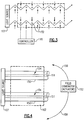
Figure 3 illustrates another embodiment of the invention. In this embodiment, a cross-sectional dimension of thewaveguide 150 can be varied to control light delivery to the item for making the irradiance profile uniform and/or for matching the irradiance profile with the fluid flow profile. Decreasing the cross-sectional area of a waveguide in, for example, a direction substantially perpendicular to a light propagation direction increases light leakage from the waveguide. Thus, waveguides in areas where the irradiance profile is low relative to other areas, and/or areas experiencing high fluid flow profiles may have their cross-sectional areas reduced to increase light leakage, and therefore increase the number of photons, in those areas. Like the other embodiments, the variations in this embodiment can be conducted either during manufacturing to form astatic waveguide 150 or during operation of the system itself as adynamic waveguide 150. - Devices used to decrease the cross-sectional area of the
waveguide 150 may include, for example, devices that stretch and/or twist the waveguide (e.g., if the waveguide is made of a resilient material). In the illustrated dynamic embodiment, thewaveguides 150 may be made of a resilient material and have fixed ends. At least onewaveguide 150 is connected to actuators 152 that can move to stretch or release thewaveguide 150 and thereby reduce or increase its cross-sectional area, respectively. Theactuators 152 are controlled by thecontroller 116 so that the amount of stretching or releasing corresponds to the desired irradiance profile. Theactuators 152 can move in any manner and in any direction that will facilitate stretching and releasing. In the illustrated embodiment, theactuators 152 are in the form of pins that are operated from above the pins to stretch or release thewaveguide 150 in a given area. - In another example where the
waveguides 150 are glass plates, for example, the cross-sectional area can be changed by changing a distance, and therefore an air gap, between the two plates. As noted above, matching the irradiance profile with the fluid flow profile can be conducted either as a single setting or as a dynamic process that changes as the fluid flow profile changes. -
Figure 4 illustrates yet another embodiment of the invention. Rather than changing the curvature or the cross-sectional area of thewaveguides 150, this embodiment changes the refractive index of thewaveguide cladding 154. As noted above, light leakage from thewaveguide 150 is a function of the relative refractive indices of thecore 151 of thewaveguide 150 and itscladding 154. Thecore 151 generally has a higher refractive index, to varying degrees, than thecladding 154. By modifying the refractive index of thecladding 154 to a value closer to the refractive index of thecore 151, the decrease in the difference between the two refractive indices increases the light leakage from thecore 151 through thecladding 154. This modification can be conducted during waveguide manufacture to form thestatic light distributor 106. - In a
dynamic light distributor 106, thecladding 154 of thewaveguide 150 comprises a birefringent material whose light propagation characteristics can change based on characteristics of an electric ormagnetic field 158 generated near thewaveguide 150 by a field generator, which acts as theactuator 152. Thecontroller 116 can therefore change the refractive index of thecladding 154 by modulating the characteristics of the field. Thus, increasing the refractive index of thecladding 154 can be used to increase the percentage of incident light leakage in areas where the irradiance profile is lower and/or areas where the fluid flow is highest on the photocatalytic surface. The refractive index can also be altered by other influences, such as temperature, pressure, or mechanical strain. -
Figure 5 illustrates yet another embodiment of the invention. The embodiment shown inFigure 5 focuses on altering surface roughness, which in essence is altering local variations in curvature, in thewaveguide 150 to control light leakage. For example, increasing the density and decreasing the size of local variations in the surface roughness of the waveguide may increase light leakage. Like the previous embodiments,certain waveguides 150 are selected for modification in surface roughness based on, for example, whether their irradiation profile needs to be increased to compensate for the higher profile closer to thelight source 107 or whether the fluid flow profile is greater at a given area, thereby requiring increased light leakage in that area to optimize reactor efficiency. As shown in the Figure, roughenedareas 160 on the waveguide surface may be disposed at selected areas during waveguide manufacture to change the light leakage in those areas. - The surface roughness can be controlled during waveguide manufacture by, for example, sandblasting or adding lumps of material to selected areas of the
waveguide 150. In this embodiment, thewaveguide 150 may contain core material only, with no cladding, to provide greater control over the light leakage characteristics during manufacture to form astatic light distributor 106. -
Figure 6 illustrates a further embodiment of the invention. In this embodiment, it is assumed that thewaveguide 150 has scatteringcenters 202 that affect light leakage from thewaveguide 150 by scattering light out of thewaveguide 150. For clarity, thewaveguide 150 in this example is illustrated to have a plate-like shape; however, this embodiment can be applied to waveguides of any shape. - The local scattering centers 202 can be, for example, hollow regions (e.g., bubbles) or solid particles distributed within the waveguide material, with each scattering center comprising one bubble or particle that scatters light. The regions and/or particles that create the scattering centers can have any shape and size (e.g., regular, irregular, macroscopic, microscopic, etc.), depending on the desired light leakage effect. In one embodiment, the
actuator 152 can vary the density and size of the scattering centers 202 in the waveguide as well as completely create and eliminate scattering centers 202. For example, increasing the density of the scattering centers 202 in areas away from thelight source 107 will help compensate for any reduced internal irradiation, thereby achieving more uniform light delivery to the photocatalytic surface of theitem 104. Similarly, increasing the density of scatteringcenters 202 in areas experiencing higher fluid flow profile values increases the light leakage, and therefore the number of photons, to accommodate the extra target chemical species due to the higher fluid flow. These scattering centers 202 may be formed during waveguide manufacture for astatic light distributor 106. - In the dynamic light distributor example, the
waveguide 150 may include one or more scattering centers formed ofparticles 202 that exhibit precipitation characteristics where the particles precipitate and dissolve back into thewaveguide material 150 depending on the temperature of the environment. Local areas of phase change materials that respond to temperature changes can also act as temperature-controlled scattering centers similar to the precipitation particles. Thecontroller 116 can therefore modify the irradiance profile by changing the temperature in different areas of thewaveguide 150. In another example, thewaveguide 150 may includeparticles 202 of liquid crystal material whose light transmission characteristics are controlled by an orientation and/or strength of an electric field. Thus, thecontroller 116 can change the light leakage characteristics of the scattering centers by changing the electric field, thereby changing the orientation of theliquid crystal particles 202. - In the embodiments described above, the
waveguides 150 can have any shape and are not limited to the cylindrical shapes as shown. For example, the waveguides can be formed as straight or curved cylinders, plates, optical foam, or fibers having a circular, curved or polygonal cross-section. -
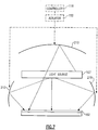
Figure 7 illustrates a side view of yet another embodiment of the invention applicable to systems where the light is not guided by total internal reflection like the waveguide examples described above. In this embodiment, the irradiance profile is controlled by one ormore reflectors 210 near thelight source 107. Thereflectors 210 can be shaped to achieve a uniform irradiance profile and/or match the fluid flow profile. In one embodiment, thereflector 210 is made of a resilient reflective material that can be bent and reshaped based on the detected fluid flow profile so that thereflector 210 causes the irradiance profile to match the fluid flow profile. Alternatively, or in addition, thecontroller 116 can reorient selectedreflectors 210 to reflect light from thelight source 107 in different directions at any given time using known adaptive optics techniques. -
Figure 8 illustrates a side view of another embodiment of the invention applicable to systems that do not use total internal reflection to guide light. In this embodiment, one ormore lenses 220 are used to guide light from thelight source 107 to the photocatalytic surface. The shape and/or orientation of thelenses 220 can modify the irradiance profile to improve uniformity and/or match a fluid flow profile. The orientation of thelenses 220 can be controlled by thecontroller 116 based on the desired irradiance profile. Note thatlenses 220 andreflectors 210 can be used together in thesame reactor 100 to provide greater control over the irradiance profile. - Regardless of the specific embodiment used to control the irradiance profile of the light delivery system, the inventive system can be used to match an irradiance profile with a fluid flow profile either statically (where the irradiance profile reflects the fluid flow profile at a selected point in time) or dynamically (where the irradiance profile changes as the fluid flow changes) and can also be used to compensate for lower irradiance profile values in areas of the
reactor 100 away from thelight source 107. - Although the embodiments described above have been described as separate embodiments, it is possible to combine two or more embodiments in the
same reactor 100 without departing from the scope of the invention. Also, even though the above examples describe a light delivery system for a photoreactor, the light delivery system can be used in other applications without departing from the scope of the invention. Those of ordinary skill in the art will recognize that applications other than photoreactors may desire light delivery systems that have a uniform irradiance profile and/or have a profile that can be controlled to match a desired irradiance profile. Further, those of ordinary skill in the art will recognize that the irradiance profile can be controlled using methods and systems other than those specifically set forth above without departing from the scope of the invention. - It should be understood that various alternatives to the embodiments of the invention described herein may be employed in practicing the invention. It is intended that the following claims define the scope of the invention and that the method and apparatus within the scope of these claims and their equivalents be covered thereby.
Claims (29)
- A light delivery control system for a photoreactor (100), comprising:a light source (107) that generates light having an irradiance profile; anda light distributor (106) that distributes light from the light source to modify the irradiance profile of the light source; anda fluid flow sensor (110) and a light sensor (112); anda controller (114, 116) that receives data from said fluid flow sensor and the light sensor and controls the light distributor, via an actuator (152), to modify the irradiance profile based on the received data,characterised in that:the light delivery control system comprises a photocatalyst surface (102);the light distributor (106) is configured to distribute the light from the light source on to the photocatalyst surface (102); andthe controller (114, 116) is configured to control the light distributor (106) to change the irradiance profile of the light reaching the photocatalyst surface (102), said light irradiance profile being changeable between an irradiance profile that is uniform and an irradiance profile that matches the irradiance profile with the fluid flow profile.
- The light delivery control system of claim 1, wherein the light distributor (106) is at least one waveguide (150).
- The light delivery control system of claim 2, wherein said at least one waveguide (150) has a radius of curvature that modifies the irradiance profile.
- The light delivery control system of claim 2, wherein said at least one waveguide (150) has a structure selected from the group consisting of cylinders, plates, foam, circular cross-section fibers, curved cross-section fibers, and polygonal cross-section fibers.
- The light delivery control system of claim 2, wherein said at least one waveguide (150) has at least one scattering center (202).
- The light delivery control system of claim 5, wherein said at least one scattering center (202) comprises at least one selected from the group consisting of a hollow region, a solid particle, and a liquid crystal material distributed in at least a portion of the waveguide.
- The light delivery control system of claim 1, wherein the light distributor (106) comprises at least one reflector.
- The light delivery control system of claim 1, wherein the light distributor (106) comprises at least one lens.
- The light delivery control system of claim 2, wherein the actuator (152) is operably coupled to said at least one waveguide (150), wherein the actuator controls the amount of light leakage from said at least one waveguide by controlling a radius of curvature of at least one waveguide.
- The light delivery control system of claim 2, wherein the actuator (152) is operably coupled to the waveguide (150), wherein the actuator controls the amount of light leakage from said at least one waveguide by controlling a cross-sectional area of at least one waveguide.
- The light delivery control system of claim 2, wherein said at least one waveguide (150) comprises a core (151) having a first refractive index and a cladding (154) having a second refractive index, and wherein the actuator (152) is operably coupled to said at least one waveguide, wherein the actuator controls the amount of light leakage from said at least one waveguide by controlling a relationship between the first and second refractive indices.
- The light delivery control system of claim 11, wherein the actuator (152) controls at least one of a temperature, a pressure, a mechanical strain, an electric field, and a magnetic field in an area near said at least one waveguide (150).
- The light delivery control system of claim 2, wherein said at least one waveguide (150) has at least one scattering center (202), and wherein the actuator (152) is operably coupled to said at least one waveguide, wherein the actuator controls the amount of light leakage from at least one waveguide by controlling a characteristic of said at least one scattering center.
- The light delivery control system of claim 13, wherein the actuator (152) controlling the characteristic of said at least one scattering center (202) by conducting a step selected from the group of creating, eliminating, and modifying said at least one scattering center.
- The light delivery control system of claim 13, wherein said at least one scattering center (202) is selected from the group consisting of particles, bubbles, and liquid crystal material, and wherein the actuator (152) controls at least one of a temperature, an electric field, and a magnetic field in an area near said at least one waveguide (150).
- The light delivery control system of claim 1, wherein the light distributor (106) comprises at least one reflector (210), and wherein the actuator (152) controls at least one of a shape, a position and an orientation of the reflector with respect to the light source (107) to modify the irradiance profile.
- The light delivery control system of claim 1, wherein the light distributor (106) comprises at least one lens (220), and wherein the actuator (152) controls at least one of a shape, a position and an orientation of said at least one lens with respect to the light source (107) to modify the irradiance profile.
- The light delivery control system of claim 17, wherein the light distributor (106) further comprises at least one reflector (210), and wherein the actuator (152) further controls at least one of a shape, a position and an orientation of the reflector with respect to the light source (107) to modify the irradiance profile
- A method of controlling light delivery to a photocatalytic surface, comprising:determining a desired irradiance profile for illuminating the photocatalytic surface;comparing an irradiance profile of a light source (107) with the desired irradiance profile;monitoring a fluid flow profile; andmodifying the irradiance profile, via an actuator (152), to match the desired irradiance profile, wherein the desired irradiance profile is based on the fluid flow profile,wherein the desired irradiance profile is changeable between an irradiance profile that is uniform and an irradiance profile that matches the irradiance profile with the fluid flow profile, andwherein the modifying step comprises changing between the irradiance profile that is uniform and the irradiance profile that matches the irradiance profile with the fluid flow profile.
- The method of claim 19, wherein the light delivery to the photocatalytic surface is conducted by a plurality of waveguides (150), and wherein the modifying step comprises controlling an amount of light leakage from at least one of said plurality of waveguides.
- The method of claim 20, wherein the step of controlling the amount of light leakage comprises controlling a radius of curvature of at least one waveguide (150).
- The method of claim 20, wherein the step of controlling the amount of light leakage comprises controlling a cross-sectional area of said at least one waveguide (150).
- The method of claim 20, wherein at least one of said plurality of waveguides (150) comprises a core (151) having a first refractive index and a cladding (154) having a second refractive index, and wherein the step of controlling the amount of light leakage comprises controlling a relationship between the first and second refractive indices.
- The method of claim 23, wherein the step of controlling the refractive index comprises controlling at least one of a temperature, a pressure, a mechanical strain, an electric field, and a magnetic field in an area near said at least one waveguide.
- The method of claim 20, wherein at least one of said plurality of waveguides (150) has at least one scattering center (202), and wherein the step of controlling the amount of light leakage comprises controlling a characteristic of said at least one scattering center.
- The method of claim 25, wherein the step of controlling the characteristic of said at least one scattering center (202) comprises conducting a step selected from the group of creating, eliminating, and modifying said at least one scattering center.
- The method of claim 25, wherein said at least one scattering center (202) is selected from the group consisting of particles, bubbles, and liquid crystal material, and wherein the step of controlling comprises controlling at least one of a temperature, an electric field, and a magnetic field in an area near said at least one waveguide (150).
- The method of claim 19, wherein the light distributor (106) comprises at least one reflector (210), and wherein the step of controlling the amount of light leakage comprises controlling at least one of a shape, a position and an orientation of the reflector with respect to the light source (107).
- The method of claim 19, wherein the light distributor (106) comprises at least one lens (220), and wherein the step of controlling the amount of light leakage comprises controlling at least one of a shape, a position and an orientation of said at least one lens with respect to the light source (107) to modify the irradiance profile.
Applications Claiming Priority (2)
| Application Number | Priority Date | Filing Date | Title |
|---|---|---|---|
| US10/827,655 US7307704B2 (en) | 2004-04-19 | 2004-04-19 | Light delivery control system and method |
| PCT/US2005/011608 WO2005106430A2 (en) | 2004-04-19 | 2005-04-07 | Light delivery control system and method |
Publications (3)
| Publication Number | Publication Date |
|---|---|
| EP1738154A2 EP1738154A2 (en) | 2007-01-03 |
| EP1738154A4 EP1738154A4 (en) | 2010-08-04 |
| EP1738154B1 true EP1738154B1 (en) | 2018-11-14 |
Family
ID=35095924
Family Applications (1)
| Application Number | Title | Priority Date | Filing Date |
|---|---|---|---|
| EP05732624.1A Ceased EP1738154B1 (en) | 2004-04-19 | 2005-04-07 | Light delivery control system and method |
Country Status (7)
| Country | Link |
|---|---|
| US (2) | US7307704B2 (en) |
| EP (1) | EP1738154B1 (en) |
| JP (1) | JP2007532983A (en) |
| KR (1) | KR20060132989A (en) |
| CA (1) | CA2562308A1 (en) |
| MX (1) | MXPA06012097A (en) |
| WO (1) | WO2005106430A2 (en) |
Families Citing this family (10)
| Publication number | Priority date | Publication date | Assignee | Title |
|---|---|---|---|---|
| KR100860763B1 (en) | 2006-10-19 | 2008-09-29 | 부산대학교 산학협력단 | Plastic thin film optical waveguide, its manufacturing method and anti-jamming sensor using the optical waveguide |
| JP4827700B2 (en) * | 2006-11-24 | 2011-11-30 | ナガノサイエンス株式会社 | Light stability test equipment |
| US7806543B2 (en) * | 2007-01-03 | 2010-10-05 | Hill Phoenix, Inc. | Light system for a temperature controlled case |
| WO2009018498A2 (en) * | 2007-08-01 | 2009-02-05 | Bionavitas, Inc. | Illumination systems, devices, and methods for biomass production |
| CA2890373C (en) * | 2013-10-20 | 2022-04-12 | Mtt Innovation Incorporated | Light field projectors and methods |
| JP6788504B2 (en) | 2014-05-15 | 2020-11-25 | エムティティ イノベーション インコーポレイテッドMtt Innovation Incorporated | Optimizing drive scheme for multiple projector systems |
| US11779898B2 (en) | 2017-06-27 | 2023-10-10 | Syzygy Plasmonics Inc. | Photocatalytic reactor system |
| MY199482A (en) | 2017-06-27 | 2023-11-01 | Syzygy Plasmonics Inc | Photocatalytic reactor having multiple photocatalytic reactor cells |
| WO2020146799A1 (en) * | 2019-01-10 | 2020-07-16 | Syzygy Plasmonics Inc. | Optically transparent reactor cells for plasmonic photocatalytic chemical reactions using artificial light |
| JP2023128562A (en) * | 2022-03-03 | 2023-09-14 | 富士電機株式会社 | photoreactor module |
Citations (3)
| Publication number | Priority date | Publication date | Assignee | Title |
|---|---|---|---|---|
| US4204956A (en) * | 1978-10-02 | 1980-05-27 | Flatow Robert E | Water purification system |
| US4816145A (en) * | 1984-01-16 | 1989-03-28 | Autotrol Corporation | Laser disinfection of fluids |
| DE3942514A1 (en) * | 1989-03-08 | 1990-09-13 | Jenoptik Jena Gmbh | Automatic adjustment system for microscope illumination device - uses photosensor signal and detected beam position to adjust optical elements |
Family Cites Families (17)
| Publication number | Priority date | Publication date | Assignee | Title |
|---|---|---|---|---|
| US3559555A (en) * | 1968-06-04 | 1971-02-02 | John N Street | Image monitoring and control system |
| US3838908A (en) * | 1973-02-22 | 1974-10-01 | Rca Corp | Guided light structures employing liquid crystal |
| DE2840493A1 (en) * | 1978-09-18 | 1980-03-27 | Siemens Ag | FREQUENCY SELECTIVE OPTICAL LIGHT DISTRIBUTION ELEMENT AND METHOD FOR THE PRODUCTION THEREOF |
| DE2851646A1 (en) * | 1978-11-29 | 1980-07-17 | Siemens Ag | COUPLING ELEMENT FOR UNCOUPLING A LIGHT PART FROM AN OPTICAL WAVE GUIDE, AND IN COUPLING ITSELF INTO A DIVERSING OPTICAL WAVE GUIDE |
| US4506275A (en) * | 1981-07-13 | 1985-03-19 | Dainippon Screen Manufacturing Co., Ltd. | Image scanning and recording device |
| GB8313484D0 (en) * | 1983-05-16 | 1983-06-22 | King L H | Optical waveguide |
| US5019710A (en) * | 1989-03-30 | 1991-05-28 | Measurex Corporation | Optical system for detecting properties of traveling sheet materials |
| ATE124225T1 (en) * | 1991-08-12 | 1995-07-15 | Avl Medical Instr Ag | DEVICE FOR MEASURING AT LEAST ONE GAS SATURATION, IN PARTICULAR THE OXYGEN SATURATION OF BLOOD. |
| DE4330784C2 (en) * | 1993-09-10 | 1999-12-30 | Siemens Ag | X-ray diagnostic device |
| US5919422A (en) * | 1995-07-28 | 1999-07-06 | Toyoda Gosei Co., Ltd. | Titanium dioxide photo-catalyzer |
| US6238630B1 (en) * | 1998-09-02 | 2001-05-29 | Keiji Iimura | Photocatalyst device and photocatalyst reactor |
| CA2268469C (en) * | 1998-04-10 | 2004-03-23 | University Of Central Florida | Apparatus and method for photocatalytic and thermocatalytic pollution control |
| US6771866B2 (en) * | 1998-09-02 | 2004-08-03 | Keiji Iimura | Photocatalyst apparatus, method of manufacture thereof and photocatalyst reactor |
| US6278100B1 (en) * | 1999-05-04 | 2001-08-21 | Ball Aerospace & Technologies Corp. | Synthetic guide star for on-orbit assembly and configuration of large earth remote sensing optical systems |
| US6902653B2 (en) * | 1999-11-22 | 2005-06-07 | Titan Technologies | Apparatus and method for photocatalytic purification and disinfection of fluids |
| DE50113159D1 (en) * | 2000-05-10 | 2007-12-06 | Regent Beleuchtungskoerper Ag | Light distributor for a lighting device and lighting device and use of a lighting device |
| US6995355B2 (en) * | 2003-06-23 | 2006-02-07 | Advanced Optical Technologies, Llc | Optical integrating chamber lighting using multiple color sources |
-
2004
- 2004-04-19 US US10/827,655 patent/US7307704B2/en not_active Expired - Lifetime
-
2005
- 2005-04-07 WO PCT/US2005/011608 patent/WO2005106430A2/en not_active Ceased
- 2005-04-07 JP JP2007509495A patent/JP2007532983A/en not_active Withdrawn
- 2005-04-07 KR KR1020067020551A patent/KR20060132989A/en not_active Ceased
- 2005-04-07 CA CA002562308A patent/CA2562308A1/en not_active Abandoned
- 2005-04-07 EP EP05732624.1A patent/EP1738154B1/en not_active Ceased
- 2005-04-07 MX MXPA06012097A patent/MXPA06012097A/en not_active Application Discontinuation
-
2007
- 2007-10-30 US US11/927,731 patent/US7505123B2/en not_active Expired - Fee Related
Patent Citations (3)
| Publication number | Priority date | Publication date | Assignee | Title |
|---|---|---|---|---|
| US4204956A (en) * | 1978-10-02 | 1980-05-27 | Flatow Robert E | Water purification system |
| US4816145A (en) * | 1984-01-16 | 1989-03-28 | Autotrol Corporation | Laser disinfection of fluids |
| DE3942514A1 (en) * | 1989-03-08 | 1990-09-13 | Jenoptik Jena Gmbh | Automatic adjustment system for microscope illumination device - uses photosensor signal and detected beam position to adjust optical elements |
Also Published As
| Publication number | Publication date |
|---|---|
| US20080049432A1 (en) | 2008-02-28 |
| US7505123B2 (en) | 2009-03-17 |
| EP1738154A2 (en) | 2007-01-03 |
| WO2005106430A3 (en) | 2007-02-22 |
| CA2562308A1 (en) | 2005-11-10 |
| JP2007532983A (en) | 2007-11-15 |
| WO2005106430A2 (en) | 2005-11-10 |
| US7307704B2 (en) | 2007-12-11 |
| EP1738154A4 (en) | 2010-08-04 |
| US20050231711A1 (en) | 2005-10-20 |
| MXPA06012097A (en) | 2007-01-25 |
| KR20060132989A (en) | 2006-12-22 |
Similar Documents
| Publication | Publication Date | Title |
|---|---|---|
| US7505123B2 (en) | Light delivery control system and method | |
| US6151169A (en) | Sheet type optical device and backlighting unit using the same | |
| KR101210099B1 (en) | Optical substrate and method of making | |
| JP4432039B2 (en) | Surface lighting device | |
| KR100370526B1 (en) | Liquid crystal display apparatus | |
| CN101821648B (en) | Prismatic curved sheet optical device for use in curved display | |
| JP2010251318A (en) | Irradiation device using reflector, lighting system, and condenser | |
| KR20090104077A (en) | Incoupling Structures for Lighting Applications | |
| US20060239629A1 (en) | Elliptical diffusers used in displays | |
| CN1238045A (en) | A divergent angle rotator system and method for collimating light | |
| JP2005196188A (en) | OPTICAL SUBSTRATE WITH FACET FORMED, METHOD FOR PRODUCING FACET OPTICAL SUBSTRATE, AND BACKLIGHT DISPLAY HAVING THE FACET OPTICAL BOARD | |
| US20100135043A1 (en) | Composite light guiding curved surface structure | |
| JP2006058839A (en) | Light guide plate | |
| CN113805267A (en) | Light guide plate and backlight source structure | |
| TWI240829B (en) | Light-guide type diffusive uniform light device | |
| CN111221062B (en) | Display device | |
| US8382360B2 (en) | Symmetric serrated edge light guide film having elliptical base segments | |
| EP3709074A1 (en) | Optical element and laser irradiation device | |
| US8491172B2 (en) | Symmetric serrated edge light guide film having elliptical base segments | |
| US20100265588A1 (en) | Optical adjusting apparatus with composite pattern structure | |
| CN105759335B (en) | Light guide plate, backlight module and display device | |
| WO2014024374A1 (en) | Surface light source device and display device | |
| KR100918243B1 (en) | Lighting device for evenly retroilluminating flat-panel monitors, comprising a fiber optic light guide having diffractive surface elements | |
| US20020048176A1 (en) | Cusp illuminator and flat panel illuminator made thereby | |
| KR20090008861A (en) | Lighting system with reflective cap to improve light distribution efficiency |
Legal Events
| Date | Code | Title | Description |
|---|---|---|---|
| PUAI | Public reference made under article 153(3) epc to a published international application that has entered the european phase |
Free format text: ORIGINAL CODE: 0009012 |
|
| 17P | Request for examination filed |
Effective date: 20061020 |
|
| AK | Designated contracting states |
Kind code of ref document: A2 Designated state(s): AT BE BG CH CY CZ DE DK EE ES FI FR GB GR HU IE IS IT LI LT LU MC NL PL PT RO SE SI SK TR |
|
| AX | Request for extension of the european patent |
Extension state: AL BA HR LV MK YU |
|
| PUAK | Availability of information related to the publication of the international search report |
Free format text: ORIGINAL CODE: 0009015 |
|
| RIC1 | Information provided on ipc code assigned before grant |
Ipc: G01N 21/00 20060101AFI20070314BHEP Ipc: F21V 11/14 20060101ALI20070314BHEP |
|
| DAX | Request for extension of the european patent (deleted) | ||
| RBV | Designated contracting states (corrected) |
Designated state(s): CH DE FR GB IT LI |
|
| A4 | Supplementary search report drawn up and despatched |
Effective date: 20100705 |
|
| 17Q | First examination report despatched |
Effective date: 20110412 |
|
| RIC1 | Information provided on ipc code assigned before grant |
Ipc: G02B 6/14 20060101ALI20131011BHEP Ipc: G06F 17/50 20060101ALI20131011BHEP Ipc: F21V 8/00 20060101AFI20131011BHEP Ipc: F21V 11/14 20060101ALI20131011BHEP Ipc: G01N 21/00 20060101ALI20131011BHEP Ipc: G02B 6/00 20060101ALI20131011BHEP |
|
| GRAP | Despatch of communication of intention to grant a patent |
Free format text: ORIGINAL CODE: EPIDOSNIGR1 |
|
| INTG | Intention to grant announced |
Effective date: 20161005 |
|
| GRAJ | Information related to disapproval of communication of intention to grant by the applicant or resumption of examination proceedings by the epo deleted |
Free format text: ORIGINAL CODE: EPIDOSDIGR1 |
|
| STAA | Information on the status of an ep patent application or granted ep patent |
Free format text: STATUS: EXAMINATION IS IN PROGRESS |
|
| INTC | Intention to grant announced (deleted) | ||
| GRAJ | Information related to disapproval of communication of intention to grant by the applicant or resumption of examination proceedings by the epo deleted |
Free format text: ORIGINAL CODE: EPIDOSDIGR1 |
|
| GRAS | Grant fee paid |
Free format text: ORIGINAL CODE: EPIDOSNIGR3 |
|
| STAA | Information on the status of an ep patent application or granted ep patent |
Free format text: STATUS: GRANT OF PATENT IS INTENDED |
|
| INTC | Intention to grant announced (deleted) | ||
| GRAP | Despatch of communication of intention to grant a patent |
Free format text: ORIGINAL CODE: EPIDOSNIGR1 |
|
| INTG | Intention to grant announced |
Effective date: 20180528 |
|
| GRAA | (expected) grant |
Free format text: ORIGINAL CODE: 0009210 |
|
| STAA | Information on the status of an ep patent application or granted ep patent |
Free format text: STATUS: THE PATENT HAS BEEN GRANTED |
|
| AK | Designated contracting states |
Kind code of ref document: B1 Designated state(s): CH DE FR GB IT LI |
|
| REG | Reference to a national code |
Ref country code: GB Ref legal event code: FG4D |
|
| REG | Reference to a national code |
Ref country code: CH Ref legal event code: EP |
|
| REG | Reference to a national code |
Ref country code: DE Ref legal event code: R082 Ref document number: 602005054977 Country of ref document: DE Representative=s name: SCHMITT-NILSON SCHRAUD WAIBEL WOHLFROM PATENTA, DE |
|
| REG | Reference to a national code |
Ref country code: DE Ref legal event code: R096 Ref document number: 602005054977 Country of ref document: DE |
|
| REG | Reference to a national code |
Ref country code: CH Ref legal event code: NV Representative=s name: VALIPAT S.A. GEVERS SA, CH |
|
| REG | Reference to a national code |
Ref country code: CH Ref legal event code: PCAR Free format text: NEW ADDRESS: RUE DES NOYERS 11, 2000 NEUCHATEL (CH) |
|
| PGFP | Annual fee paid to national office [announced via postgrant information from national office to epo] |
Ref country code: FR Payment date: 20190325 Year of fee payment: 15 Ref country code: CH Payment date: 20190326 Year of fee payment: 15 Ref country code: GB Payment date: 20190325 Year of fee payment: 15 Ref country code: IT Payment date: 20190321 Year of fee payment: 15 |
|
| PGFP | Annual fee paid to national office [announced via postgrant information from national office to epo] |
Ref country code: DE Payment date: 20190220 Year of fee payment: 15 |
|
| REG | Reference to a national code |
Ref country code: DE Ref legal event code: R097 Ref document number: 602005054977 Country of ref document: DE |
|
| PLBE | No opposition filed within time limit |
Free format text: ORIGINAL CODE: 0009261 |
|
| STAA | Information on the status of an ep patent application or granted ep patent |
Free format text: STATUS: NO OPPOSITION FILED WITHIN TIME LIMIT |
|
| 26N | No opposition filed |
Effective date: 20190815 |
|
| REG | Reference to a national code |
Ref country code: DE Ref legal event code: R119 Ref document number: 602005054977 Country of ref document: DE |
|
| REG | Reference to a national code |
Ref country code: CH Ref legal event code: PL |
|
| PG25 | Lapsed in a contracting state [announced via postgrant information from national office to epo] |
Ref country code: FR Free format text: LAPSE BECAUSE OF NON-PAYMENT OF DUE FEES Effective date: 20200430 Ref country code: LI Free format text: LAPSE BECAUSE OF NON-PAYMENT OF DUE FEES Effective date: 20200430 Ref country code: DE Free format text: LAPSE BECAUSE OF NON-PAYMENT OF DUE FEES Effective date: 20201103 Ref country code: CH Free format text: LAPSE BECAUSE OF NON-PAYMENT OF DUE FEES Effective date: 20200430 |
|
| GBPC | Gb: european patent ceased through non-payment of renewal fee |
Effective date: 20200407 |
|
| PG25 | Lapsed in a contracting state [announced via postgrant information from national office to epo] |
Ref country code: GB Free format text: LAPSE BECAUSE OF NON-PAYMENT OF DUE FEES Effective date: 20200407 |
|
| PG25 | Lapsed in a contracting state [announced via postgrant information from national office to epo] |
Ref country code: IT Free format text: LAPSE BECAUSE OF NON-PAYMENT OF DUE FEES Effective date: 20200407 |