EP1737402B1 - Calibrating laser beam position and shape using an image capture device - Google Patents
Calibrating laser beam position and shape using an image capture device Download PDFInfo
- Publication number
- EP1737402B1 EP1737402B1 EP05729130.4A EP05729130A EP1737402B1 EP 1737402 B1 EP1737402 B1 EP 1737402B1 EP 05729130 A EP05729130 A EP 05729130A EP 1737402 B1 EP1737402 B1 EP 1737402B1
- Authority
- EP
- European Patent Office
- Prior art keywords
- laser
- laser beam
- calibration surface
- imaging
- mark
- Prior art date
- Legal status (The legal status is an assumption and is not a legal conclusion. Google has not performed a legal analysis and makes no representation as to the accuracy of the status listed.)
- Expired - Lifetime
Links
Images


Classifications
-
- A—HUMAN NECESSITIES
- A61—MEDICAL OR VETERINARY SCIENCE; HYGIENE
- A61F—FILTERS IMPLANTABLE INTO BLOOD VESSELS; PROSTHESES; DEVICES PROVIDING PATENCY TO, OR PREVENTING COLLAPSING OF, TUBULAR STRUCTURES OF THE BODY, e.g. STENTS; ORTHOPAEDIC, NURSING OR CONTRACEPTIVE DEVICES; FOMENTATION; TREATMENT OR PROTECTION OF EYES OR EARS; BANDAGES, DRESSINGS OR ABSORBENT PADS; FIRST-AID KITS
- A61F9/00—Methods or devices for treatment of the eyes; Devices for putting in contact-lenses; Devices to correct squinting; Apparatus to guide the blind; Protective devices for the eyes, carried on the body or in the hand
- A61F9/007—Methods or devices for eye surgery
- A61F9/008—Methods or devices for eye surgery using laser
-
- A—HUMAN NECESSITIES
- A61—MEDICAL OR VETERINARY SCIENCE; HYGIENE
- A61B—DIAGNOSIS; SURGERY; IDENTIFICATION
- A61B18/00—Surgical instruments, devices or methods for transferring non-mechanical forms of energy to or from the body
- A61B18/18—Surgical instruments, devices or methods for transferring non-mechanical forms of energy to or from the body by applying electromagnetic radiation, e.g. microwaves
- A61B18/20—Surgical instruments, devices or methods for transferring non-mechanical forms of energy to or from the body by applying electromagnetic radiation, e.g. microwaves using laser
-
- A—HUMAN NECESSITIES
- A61—MEDICAL OR VETERINARY SCIENCE; HYGIENE
- A61F—FILTERS IMPLANTABLE INTO BLOOD VESSELS; PROSTHESES; DEVICES PROVIDING PATENCY TO, OR PREVENTING COLLAPSING OF, TUBULAR STRUCTURES OF THE BODY, e.g. STENTS; ORTHOPAEDIC, NURSING OR CONTRACEPTIVE DEVICES; FOMENTATION; TREATMENT OR PROTECTION OF EYES OR EARS; BANDAGES, DRESSINGS OR ABSORBENT PADS; FIRST-AID KITS
- A61F9/00—Methods or devices for treatment of the eyes; Devices for putting in contact-lenses; Devices to correct squinting; Apparatus to guide the blind; Protective devices for the eyes, carried on the body or in the hand
- A61F9/007—Methods or devices for eye surgery
- A61F9/008—Methods or devices for eye surgery using laser
- A61F9/00802—Methods or devices for eye surgery using laser for photoablation
-
- B—PERFORMING OPERATIONS; TRANSPORTING
- B23—MACHINE TOOLS; METAL-WORKING NOT OTHERWISE PROVIDED FOR
- B23K—SOLDERING OR UNSOLDERING; WELDING; CLADDING OR PLATING BY SOLDERING OR WELDING; CUTTING BY APPLYING HEAT LOCALLY, e.g. FLAME CUTTING; WORKING BY LASER BEAM
- B23K26/00—Working by laser beam, e.g. welding, cutting or boring
- B23K26/02—Positioning or observing the workpiece, e.g. with respect to the point of impact; Aligning, aiming or focusing the laser beam
- B23K26/03—Observing, e.g. monitoring, the workpiece
- B23K26/032—Observing, e.g. monitoring, the workpiece using optical means
-
- B—PERFORMING OPERATIONS; TRANSPORTING
- B23—MACHINE TOOLS; METAL-WORKING NOT OTHERWISE PROVIDED FOR
- B23K—SOLDERING OR UNSOLDERING; WELDING; CLADDING OR PLATING BY SOLDERING OR WELDING; CUTTING BY APPLYING HEAT LOCALLY, e.g. FLAME CUTTING; WORKING BY LASER BEAM
- B23K26/00—Working by laser beam, e.g. welding, cutting or boring
- B23K26/02—Positioning or observing the workpiece, e.g. with respect to the point of impact; Aligning, aiming or focusing the laser beam
- B23K26/06—Shaping the laser beam, e.g. by masks or multi-focusing
- B23K26/062—Shaping the laser beam, e.g. by masks or multi-focusing by direct control of the laser beam
- B23K26/0622—Shaping the laser beam, e.g. by masks or multi-focusing by direct control of the laser beam by shaping pulses
-
- B—PERFORMING OPERATIONS; TRANSPORTING
- B23—MACHINE TOOLS; METAL-WORKING NOT OTHERWISE PROVIDED FOR
- B23K—SOLDERING OR UNSOLDERING; WELDING; CLADDING OR PLATING BY SOLDERING OR WELDING; CUTTING BY APPLYING HEAT LOCALLY, e.g. FLAME CUTTING; WORKING BY LASER BEAM
- B23K26/00—Working by laser beam, e.g. welding, cutting or boring
- B23K26/70—Auxiliary operations or equipment
- B23K26/702—Auxiliary equipment
- B23K26/705—Beam measuring devices
-
- G—PHYSICS
- G01—MEASURING; TESTING
- G01J—MEASUREMENT OF INTENSITY, VELOCITY, SPECTRAL CONTENT, POLARISATION, PHASE OR PULSE CHARACTERISTICS OF INFRARED, VISIBLE OR ULTRAVIOLET LIGHT; COLORIMETRY; RADIATION PYROMETRY
- G01J1/00—Photometry, e.g. photographic exposure meter
- G01J1/42—Photometry, e.g. photographic exposure meter using electric radiation detectors
- G01J1/4257—Photometry, e.g. photographic exposure meter using electric radiation detectors applied to monitoring the characteristics of a beam, e.g. laser beam, headlamp beam
-
- A—HUMAN NECESSITIES
- A61—MEDICAL OR VETERINARY SCIENCE; HYGIENE
- A61F—FILTERS IMPLANTABLE INTO BLOOD VESSELS; PROSTHESES; DEVICES PROVIDING PATENCY TO, OR PREVENTING COLLAPSING OF, TUBULAR STRUCTURES OF THE BODY, e.g. STENTS; ORTHOPAEDIC, NURSING OR CONTRACEPTIVE DEVICES; FOMENTATION; TREATMENT OR PROTECTION OF EYES OR EARS; BANDAGES, DRESSINGS OR ABSORBENT PADS; FIRST-AID KITS
- A61F9/00—Methods or devices for treatment of the eyes; Devices for putting in contact-lenses; Devices to correct squinting; Apparatus to guide the blind; Protective devices for the eyes, carried on the body or in the hand
- A61F9/007—Methods or devices for eye surgery
- A61F9/008—Methods or devices for eye surgery using laser
- A61F2009/00855—Calibration of the laser system
-
- A—HUMAN NECESSITIES
- A61—MEDICAL OR VETERINARY SCIENCE; HYGIENE
- A61F—FILTERS IMPLANTABLE INTO BLOOD VESSELS; PROSTHESES; DEVICES PROVIDING PATENCY TO, OR PREVENTING COLLAPSING OF, TUBULAR STRUCTURES OF THE BODY, e.g. STENTS; ORTHOPAEDIC, NURSING OR CONTRACEPTIVE DEVICES; FOMENTATION; TREATMENT OR PROTECTION OF EYES OR EARS; BANDAGES, DRESSINGS OR ABSORBENT PADS; FIRST-AID KITS
- A61F9/00—Methods or devices for treatment of the eyes; Devices for putting in contact-lenses; Devices to correct squinting; Apparatus to guide the blind; Protective devices for the eyes, carried on the body or in the hand
- A61F9/007—Methods or devices for eye surgery
- A61F9/008—Methods or devices for eye surgery using laser
- A61F2009/00861—Methods or devices for eye surgery using laser adapted for treatment at a particular location
- A61F2009/00872—Cornea
Definitions
- the present invention relates generally to methods and systems for calibrating laser beam delivery systems, particularly ophthalmological surgery systems. More specifically, the present invention relates to methods and systems for calibrating a laser beam, such as a position or shape of the laser beam, from the laser beam delivery system using an image capture device.
- Laser based systems are now commonly used in ophthalmological surgery on corneal tissues of the eye to correct vision defects. These systems use lasers to achieve a desired change in corneal shape, with the laser removing microscopic layers of stromal tissue from the cornea using a technique generally described as ablative photodecomposition to alter the refractive characteristics of the eye.
- Laser eye surgery techniques are useful in procedures such as photorefractive keratotomy (PRK), phototherapeutic keratectomy (PTK), laser in situ keratomileusis (LASIK), and the like.
- Laser ablation procedures can reshape or sculpt the shape of the cornea for varying purposes, such as for correcting myopia, hyperopia, astigmatism, and other corneal surface profile defects.
- the laser beam often comprises a series of discrete pulses of laser light energy, with the total shape and amount of tissue being removed being determined by the position, shape, size, and/or number of a pattern of laser energy pulses impinging on the cornea.
- a variety of algorithms may be used to calculate the pattern of laser pulses used to reshape the cornea so as to correct a refractive error of the eye.
- laser beam delivery systems are calibrated to ensure control over the distribution of ablation energy across the cornea so as to minimize undesirable laser system performance, such as might result from flawed internal mechanical or optical components.
- calibration of the laser system helps ensure accurate removal of the intended shape and quantity of the corneal tissue so as to provide the desired shape and refractive power modification to the patient's cornea. Imprecise control of the laser beam may jeopardize the success of the surgery and could cause damage to the patient's eye.
- derivation from a desired laser beam shape, size, or position may result in tissue ablation at an undesired location on the patient's cornea which in turn leads to less than ideal corneal sculpting results.
- a desired laser beam shape, size, or position such as the laser beam exhibiting a non-symmetrical shape or an increased or decreased laser beam diameter
- Ablation of plastic test materials are often performed prior to laser surgery to calibrate the ablation shape and size of the laser beam delivery system.
- an iris or other variable diameter aperture which may be used to tailor the shape, size, and position of the laser beam is typically calibrated by directing laser pulses at different iris settings onto a clear plastic material. Eye loops are then used by an operator for manual inspection of the ablated plastic.
- Such calibration techniques are limited by many factors, such as the precision provided by the eye loops, which is typically about ⁇ 0.1 mm, and/or the vision of the operator. For example, visual measurement of shape profiles is particularly difficult and is often subject to human error. Further, such calibration techniques may not accurately measure a hysteresis of the variable diameter iris.
- increased utilization of wavefront technologies to provide customized ablations in laser eye surgery systems may be optimized by increasing the accuracy of the shape, size, and positioning of the ablating laser beam.
- WO 99/24796 describes systems and methods for calibrating laser ablations in which a plastic sheet in the form of a calibration card is placed on a supporting stage at a position corresponding to the surface of the cornea and a test surface is selectively ablated to a desired shape, preferably a lens having a refractive power.
- the test surface and a reference structure are illuminated and the resulting geographical pattern is imaged onto a photodetector.
- the reference structure may include a peripheral portion that is disposed around the ablated test surface and an inner portion that is substantially aligned with the test surface.
- the peripheral portion is not refracted by the test surface lens and is used to register the inner refractive portion.
- a ratio of spacing between the geometric elements and the peripheral portion of the reference structure is compared with the spacing between the geometric elements in the inner portion that is refracted by the lens.
- Described herein are methods and systems for calibrating a laser beam delivery system, such as an excimer laser system for selectively ablating a cornea of a patient's eye.
- improved methods and systems are provided for laser beam positioning, shape profile, and/or size profile calibration using an image capture device, such as a microscope camera.
- the methods and systems are particularly suited for iris calibration and hysteresis measurement of a variable diameter aperture. Such methods and systems further provide enhanced calibration accuracy and precision without significantly increasing the overall system cost and complexity and may be applied to a variety of laser systems.
- the imaging of the known object and of the mark on the calibration surface is carried out in the same position.
- the directing and imaging may also be carried out in the same plane.
- the directing and imaging may be carried out in at least one of a laser focus plane or an eye treatment plane, wherein imaging of the known object and imaging of the mark on the calibration surface are performed along an imaging optical path coaxial with a laser optical path.
- the directing and imaging may also be carried out in different planes.
- the laser energy may be directed onto the calibration surface at the laser focus plane while the imaging of the known object and imaging of the mark on the calibration surface are performed at the treatment plane. In a more general system, it would be preferable to focus the laser and image capture device in the same plane.
- the imaged object comprises a circular shape having a known diameter.
- the known object may comprise a circular chrome layer on a glass or crystal plate.
- the calibration surface may comprise a variety of materials, including photosensitive material, silkscreen material, Zapit paper, luminescent material, or photographic material.
- a photosensitive material is utilized, wherein the mark on the calibration surface comprises a permanent change in color, such as a white spot on a black background or vice versa, or a luminescent glow.
- the calibration surface may comprise photoreactive material, polymethylmethacrylate material, or other VISX calibration materials, available from VISX, Incorporated of Santa Clara, California.
- use of polymethylmethacrylate material may result in the mark on the calibration surface to comprise an ablation.
- the mark on the calibration surface may be associated with an iris diameter setting in a range from about 0.65 mm to about 6.7 mm.
- the pulsed laser beam diameter setting is increased over time so as to form a plurality of marks.
- the resulting marks are then imaged and compared to the known object.
- the pulsed laser beam diameter setting is decreased over time so as to form another set of marks that are imaged and compared to the known object.
- a hysteresis determination may then be determined of a variable aperture, due to changes in iris diameter setting movement directions, as well as a relationship between laser beam diameter and motor counts associated with the iris setting.
- the shape of the laser beam and a center position of the laser beam may be determined from the imaging comparison. Additionally, a drift of the laser eye surgery system may be determined by monitoring a variance in center positions for each scanned and imaged laser pulse. Still further, a laser beam deflection may be determined. In some embodiments, an optical element maybe rotated along a laser delivery path for smoothing laser beam integration, as discussed in greater detail in co-pending U.S. Patent Application No. 10/366,131, filed February 12,2003 (Publication No. US 2004-0042080 ).
- the present calibration method may also identify a rotation-induced laser induced wobble from a plurality of marks due to rotation of the optical element.
- a patient's cornea may be ablated to correct a variety of vision defects, including myopia, hyperopia, astigmatism, and other corneal surface profile defects.
- the method generally comprises imaging an object of known size with a microscope camera.
- a pulsed laser beam is scanned across a photosensitive material so as leave an ablation on the photosensitive material.
- the ablation on the photosensitive material is imaged with the microscope camera.
- An iris calibration of a laser eye surgery system is then determined by comparing the image of the ablation on the photosensitive material to the image of the known object. Finally, a patient's cornea may be ablated with the calibrated system.
- a system for calibrating laser pulses from a laser beam delivery system comprises an image capture device orientated toward a treatment plane.
- a known object is positionable for imaging by the image capture device.
- a pulsed laser beam delivery system is also provided.
- a calibration surface is supportable in an optical path of the pulsed laser beam so as to result in a mark on the calibration surface and for imaging of the mark on the calibration surface by the image capture device.
- a processor is coupled to the image capture device. The processor determines a calibration of the laser beam delivery system by comparing the image of the mark on the calibration surface to the image of the known object.
- the laser beam delivery system preferably comprises a laser eye surgery system.
- the image capture device preferably comprises a microscope camera.
- video cameras, eye tracking cameras, or other existing image capture devices and cameras already provided on the laser system may be utilized.
- the known object preferably comprises a circular chrome layer of known diameter on a glass plate.
- the known object and calibration surface are imaged in the same position, wherein the known object and calibration surface are positioned in at least one of a laser focus plane or the treatment plane.
- the calibration surface comprises photosensitive material, silkscreen material, Zapit paper, luminescent material, photoreactive material, polymethylmethacrylate material, or photographic material.
- the mark on the calibration surface comprises an ablation, a permanent change in color, or a luminescent glow and has an iris setting in a range from about 0.65 mm to about 6.7 mm.
- Described herein are methods and systems for calibrating a laser beam delivery system, such as an excimer laser system for selectively ablating a cornea of a patient's eye.
- improved methods and systems are provided for laser beam positioning, shape profile, size profile, drift, and/or deflection calibration using an image capture device, such as a microscope camera, for enhanced calibration accuracy and precision.
- the methods and systems are particularly suited for iris calibration and hysteresis measurement of a variable diameter aperture. By determining such characteristics, a desired corneal ablation treatment can be accurately effected without the laser beam becoming incident on undesired locations of corneal tissue causing off-center ablations.
- the calibration methods and systems of the present invention may be utilized upon replacement of any laser delivery system component, e.g., internal mechanical or optical components such as the iris, major optical re-alignment of the system, or problems with error generation.
- FIG. 1 an exemplary calibration system 10 constructed in accordance with the principles of the present invention for calibrating laser pulses from a laser eye surgery system is schematically illustrated.
- System 10 is particularly useful for calibrating and aligning a laser ablation system of the type used to ablate a region of the cornea in a surgical procedure, such as an excimer laser used in photorefractive keratotomy (PRK), phototherapeutic keratectomy (PTK), laser in situ keratomileusis (LASIK), and the like.
- the system 10 generally comprises a laser 12, a laser beam delivery system 14, a surface, such as a photochromic mirror 16, a known object 30, a calibration surface 18, an image capture device 20, and a PC workstation 22.
- the above depictions are for illustrative purposes only and do not necessarily reflect the actual shape, size, or dimensions of the calibration system 10. This applies to all depictions hereinafter.
- the known object 30, as illustrated in Fig. 2 is positioned along an imaging optical path 32 via a hinged support arm or mechanism 34 that allows movement of the known object 30 and calibration surface 18 in at least one of a laser focus plane or the treatment plane.
- the known object 30 may be placed on top of a block (not shown) coupled to the arm 34. In either embodiment, the known object 30 is imaged by the microscope camera 20 and then removed.
- the laser 12 typically directs an unshaped laser beam 24 through the delivery system optics 14 which in turn directs a shaped and positioned laser beam 26 towards the mirror 14 having a reflecting surface that directs the laser beam 26 onto the calibration surface 18 so as to leave a mark 28 on the calibration surface 18.
- the mark 28 on the calibration surface 18, which is positioned along the imaging optical path 32 coaxial with the laser optical path 26, is then imaged by the microscope camera 20.
- a PC workstation 22 determines a calibration of the laser beam delivery system 14 by comparing the image of the mark 28 on the calibration surface 18 to the image of the known object 30.
- the PC workstation 22 generally includes a processor, random access memory, tangible medium for storing instructions, a display, and/or other storage media such as hard or floppy drives.
- the laser 12 may include, but is not limited to, an excimer laser such as an argon-fluoride excimer laser producing laser energy with a wavelength of about 193 nm.
- Alternative lasers may include solid state lasers, such as frequency multiplied solid state lasers, flash-lamp and diode pumped solid state lasers, and the like.
- Exemplary solid state lasers include ultraviolet solid state lasers producing wavelengths of approximately 188-240 nm such as those disclosed in U.S. Patent Serial Nos. 5,144,630 , and 5,742,626 ; and in Borsutzky et al., Tunable UV Radiation at Short Wavelengths (188-240nm) Generated by Sum-Frequency Mixing in Lithium Borate, Appl. Phys. B 52, 380-384 (1991 ).
- a variety of alternative lasers might also be used, such as infrared or femtosecond lasers.
- a pulsed solid state laser emitting infrared light energy may be used as described in U.S. Patent Nos. 6,090,102 and 5,782,822 .
- the laser energy generally comprises a beam formed as a series of discrete laser pulses, and the pulses may be separated into a plurality of beamlets as described in U.S. Patent No. 6,331,177 .
- the optical delivery system 14 preferably employs the ultraviolet laser beam in corneal ablation procedures to ablate corneal tissue in a photodecomposition that does not cause thermal damage to adjacent and underlying tissue.
- Molecules at the irradiated surface are broken into smaller volatile fragments without substantially heating the remaining substrate; the mechanism of the ablation is photochemical, i.e. the direct braking of intermolecular bonds.
- the ablation removes a layer of the stroma to change its contour for various purposes, such as correcting myopia, hyperopia, and astigmatism.
- the known object 30 may comprise a circular chrome layer 36 having a 10 mm diameter on a glass plate 38.
- the use of the image of the known object 30 allows the magnification of the microscope camera to be quantified.
- a fitting routine then accurately and precisely estimates the cross-sectional shape, size, and center position of the laser beam by comparison. Matrices of such images may further be used to determine both long and short term drift of the laser eye surgery system.
- the known object 30 is imaged prior to directing the pulsed laser beam 26 onto the calibration surface 18 so that the mark 28 diameters may be calculated as the calibration procedure advances.
- the image produced may be slightly out of focus if the known image 30 is positioned at the laser focus plane due to the fact that the camera 20 is oriented towards the treatment plane. Further, the camera 20 response itself may also be responsible for some slight elliptical distortions of the image. Hence, the image of the known object 30 is initially fit to an elliptical algorithm to account for such camera distortion.
- the vertical and horizontal dimensions of the chrome dot 36 are obtained and all subsequent images of the mark 28 may be rescaled according to the relative dimensions of the image of the known object 30 and fit to a circle algorithm so that the characteristics of the laser beam may be precisely obtained. It will be appreciated that the illumination level should be set to the correct level prior to capturing any images with the camera 20.
- a beam 102 is generated from a suitable laser source 104, such as an argon fluoride (ArF) excimer laser beam source for generating a laser beam in the far ultraviolet range with a wavelength of about 193 nm.
- the laser beam 102 is directed to a beam splitter 106. A portion of the beam 102 is reflected onto an energy detector 108, while the remaining portion is transmitted through the beam splitter 106.
- the reflective beam splitter 106 may comprise a transmitting plate of partially absorbing material to attenuate the laser beam.
- the transmitted laser beam 102 is reflected by an adjustable mirror 110 that is used to align the path of the laser beam.
- a direction of the laser beam path may be controlled with adjustable prisms.
- the laser beam 102 reflects from the mirror 110 onto a rotating temporal beam integrator 112 that rotates a path of the laser beam.
- Another type of temporal beam integrator may be used to rotate the beam.
- the rotated beam emerging from the temporal integrator 112 is directed to a diffractive optic apparatus including a diffractive optic 113.
- the diffractive optic 113 is rotated with the beam 102.
- the diffractive optic is designed so that rotation of the diffractive optic 113 does not substantially change the path of the laser beam, and the path of the laser beam is stable with respect to rotation of the diffractive optic.
- the beam passes through the diffractive optic 113 and positive lens 114 and emerges as a converging beam 115.
- the converging beam 115 travels to the spatial integration plane at which a variable diameter aperture 116 is disposed.
- the spatial integration plane is disposed near the focal point of the positive lens 114.
- An apertured beam 120 emerges from the variable aperture 116.
- the variable aperture 116 is desirably a variable diameter iris combined with a variable width slit (not shown) used to tailor the shape and size profile of the beam 115 to a particular ophthalmological surgery procedure.
- the apertured beam 120 is directed onto an imaging lens 122, which may be a biconvex singlet lens with a focal length of about 125 mm.
- the beam 126 emerging from the imaging lens 122 is reflected by a mirror/beam splitter 130 onto the surgical plane 132.
- the apex of the cornea of the patient is typically positioned at the surgical plane 132.
- Imaging lens 122 may be moved transverse to the beam to offset the imaged beam in order to scan the imaged beam about the surgical treatment plane 132.
- a treatment energy detector 136 senses the transmitted portion of the beam energy at the mirror/beam splitter 130.
- a beam splitter 138, a microscope objective lens 140, and the microscope camera 20 form part of the observation optics.
- the beam splitter is preferably coupled to the microscope camera 20 to assist in iris calibration as well as for viewing and recording of the surgical procedure.
- a heads-up display may also be inserted in the optical path 134 of the microscope objective lens 140 to provide an additional observational capability.
- Other ancillary components of the laser optical system 14 such as the movable mechanical components driven by an astigmatism motor and an astigmatism angle motor, have been omitted to avoid prolixity.
- Figs. 4A and 4B exploded views of images that were scanned in a laser focus plane and imaged in an eye treatment plane are illustrated.
- the known object 30 and calibration surface 18, which are preferably imaged in the same plane may be positioned in at least one of a laser focus plane or a treatment plane.
- the imaging of the chrome dot 36 and imaging of the mark 28 on the calibration surface 18 are performed along the imaging optical path 32 coaxial with the laser optical path 26.
- the pulsed laser beam 26 is oriented towards the laser focus plane and the camera 20 is orientated towards the treatment plane, which is a few millimeters below the laser focus plane.
- Fig. 4A illustrates a 1 mm image of a mark 40 and Fig.
- the calibration surface 18 preferably comprises silkscreen or luminescent material, wherein the marks 40, 42 comprise a permanent change in color or a luminescent glow.
- the luminescent material may comprise a piece of glass, crystal, or polymer that is optically activated, such as chromium doped, and has a relatively long luminescent lifetime. Images may be recorded after each laser pulse, wherein the luminescence of the mark will have decayed before the next laser pulse is directed onto the luminescent surface.
- Figs. 5A and 5B illustrate exploded views of images that were scanned and imaged in the same plane, namely the laser focus plane.
- Fig. 5A illustrates a 1 mm image of a mark 40'
- Fig. 5B illustrates a 5 mm image of a mark 42'.
- Both images of the marks 40, 42 were created from directing the laser beam at the laser focus plane so as to create a crisp duodecahedral pattern on the calibration surface 18.
- the image of the marks 40', 42' however are also taken at the laser focus plane.
- the images produced 40', 42' may be slightly out of focus as the camera 20 is oriented towards the treatment plane, a few millimeters below the laser focus plane.
- Figs. 6A and 6B illustrate exploded views of images that were scanned and imaged in the eye treatment plane.
- Fig 5A illustrates a 1 mm image of a mark 40"
- Fig. 5B illustrates a 5 mm images of a mark 42".
- this image capture positioning involves minimal operator intervention as well, it can be seen that the defocus of the laser may result in varying gray zones, poor contrast, and other variations in the images 40", 42", which are not apparent when the laser beam is scanned in the laser focus plane.
- Fig. 7 a table summarizing image measurements from the scanning and imaging positions of Figs. 4A, 4B, 5A, and 5B as well as measurement results obtained from utilizing a Tencor Profilometer are shown.
- the first column indicates measurements made with the iris 116 set at various diameter settings from about 0.65 mm to about 6.0 mm.
- the profilometer measurements which served as the reference measurements, were taken for each iris setting as indicated in the second column.
- the third column represents image measurements that were scanned in the laser focus plane and imaged in the treatment plane, as depicted by Figs. 4A and 4B .
- the fourth column represents measurements that were scanned and imaged in the laser focus, as depicted by Figs. 5A and 5B .
- the fifth column represents any measurement variations between the third and fourth columns.
- the sixth column represents any measurement variations between the second and third columns.
- the best possible accuracy of the fit is taken to be of the order of 1 pixel, which is about 0.02 mm.
- Table 7 shows that utilizing either an up/down fit (Figs. 4A, 4B ) or an up/up fit ( Figs. 5A, 5B ) provides a relatively accurate and precise image measurement.
- the small differences between measured images, as indicated in the fifth and sixth columns are largely smaller than or of the order of the pixel resolution.
- improved image contrast such as by choosing a higher quality silkscreen or other calibration surfaces, may further minimize any variations in measurement readings.
- Figs. 8A and 8B graphs illustrating the relationship between laser beam diameter and motor counts associated with the iris setting are depicted.
- the first ten are carried out by increasing the laser beam diameter setting of the iris 116 over time from 0.7 mm, 1.0 mm, 1.5 mm, 2.0 mm, 2.5 mm, 3 mm, 4 mm, 5 mm, 6 mm, and 6.5 mm.
- Each mark or ablation is produced by firing 100 pulses at 20 Hz with energy between 180-220 mJ from the laser 12 onto the calibration surface 18.
- a one second pause allows any smoke to dissipate prior to capturing the image of the mark 28 with the camera 20 and calculating the measured iris diameter by comparison to the known object 30.
- the next 100 pulses are then fired at the next increasing diameter without moving the calibration surface 18. This routine will continue through the 6.5 mm setting and will take about one minute.
- the second set of marks or ablations 28 will proceed in a similar manner except that a new calibration surface or a different place on the existing calibration surface will be utilized and the iris 116 will be cycled to the 6.7 mm diameter setting wherein the pulsed laser beam diameter setting is decreased over time.
- the scanning and imaging process is time efficient in that it generally takes less than three minutes to complete.
- any hysteresis due to changes in iris diameter setting movement directions may be determined for the iris 116 and accounted for.
- both sets of data may be used to produce interpolation curves for determining an accurate relationship between measured laser beam diameter and motor counts associated with an iris aperture.
- Figs. 8A and 8B Typical results are shown in Figs. 8A and 8B for two different laser systems.
- the data obtained from the calibration procedure is fit into two quadratic lines, one for increasing laser beam diameter setting (closed to open) and one for decreasing laser beam diameter setting (open to closed).
- both irises 116 have similar characteristics.
- the best fit quadratic expressions suggest that there is a small amount of nonlinearity that should to taken into consideration.
- the best fit for determining a relationship between laser beam diameter and motor counts associated with the iris is a quadratic fit, rather than a linear fit relationship, for iris calibration purposes.
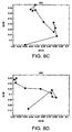
- FIGs. 8C and 8D further illustrate iris measurements from “closed to open” and “open to closed” respectively to capture the hysteresis of the iris.
- the dots represent center.
- a drift of the laser eye surgery system 14 may be determined by monitoring a variance in center positions for each scanned and imaged laser pulse. It will be appreciated that drifts may be dependent upon several factors, such as the manner in which the laser is used between measurements, the particular set of system parameters, and/or changes in environmental conditions such as temperature. Still further, a laser beam deflection may be determined. As the iris 116 changes diameter, the center of the aperture may shift slightly. As a result of the calculations already performed, the center of the best fit to the shape of the dodecagon pattern on the calibration surface has been determined for each iris size. A plot of the x and y positions of the shape center can then be computed as a function of iris diameter.
- Best fit lines can be independently fit through the x and y positions as a function of iris diameters. Hence, when a particular diameter is required by a treatment the necessary correction for the shift of the laser beam can be calculated from these lines and the laser beam target position adjusted accordingly.
- the techniques of the present invention can also be applied to judge the stability of the laser delivery system 14.
- the calibration arm 34 supporting the calibration surface 18 may comprise a luminescent plate. After each laser pulse, an image is captured while the plate is still emitting light. Images are then analyzed as described above. The center positions are calculated and may be plotted on x and y axes so that the plot provides a map of where the laser pulses landed. This plot can then be used to determine any systematic movement of the laser beam with time. Alternatively, the raw data can be used to determine parameters such as the statistical variations in x and y positions.
- a number of the optical elements in the optical system 14 may be rotated along the laser delivery path, as described in detail in co-pending U.S. Patent Application No. 10/366,131 , to distribute any distortion caused by imperfections of the optical elements.
- the lens 114 is rotated around its axis.
- the beam splitter 106 may be moved along its plane; the mirror 110 may be moved along its plane; the diffractive optic 113 may be moved in its plane, and the mirror/beam splitter 130 may be moved along its plane.
- the present invention may also be utilized to identify a rotation-induced laser induced wobble from a plurality of marks. Analysis of images of the marks may help account for these small deviations due to rotation of the optical element.
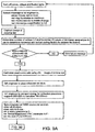
- FIG. 9A simplified flowcharts illustrate a method for calibrating laser pulses employing the system of Fig. 1 .
- the operator will begin by adjusting the illumination of the microscope camera 20 by turning the ring illumination setting to maximum and all other illuminations settings (e.g., reticle, oblique, and fixation lights) off.
- the chrome dot 36 is placed on a block coupled to the calibration arm 34.
- the microscope iris and magnification are also set.
- the image of the chrome dot 36 is then captured and the number of vertical and horizontal pixels of the dot image 36 calculated using an elliptical algorithm.
- the acceptable range for pixels in both directions is 420-460 and the values should be within 5% of each other.
- the pixel tolerance is met, the pixel to mm ratio is determined using the vertical to horizontal pixel ratio of the dot image 36.
- the operator than replaces a calibration plastic 18, such as a silkscreen, for the chrome dot 36 and sets the laser energy for the calibration procedure between 180-220 mJ, preferably to 200-220 mJ, the spin integrator at 78580 counts, and the iris setting to 0.65 mm. All shutters and slits are open, the x and y positions are set to 0, and the forward/backward parameter is set to F.
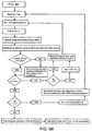
- the iris setting is changed to 0.7 mm so that the iris is being opened (increasing laser beam diameter setting).
- Each mark or ablation is produced by firing 100 pulses at 20 Hz with a one second pause to allow any smoke to dissipate prior to capturing the image of the mark 28 with the camera 20.
- the capture image is rescaled according to the relative dimensions of the image of the known object 30 and fit to a circle algorithm so that the diameter of the laser beam may be precisely obtained. If the measured value is within 10% of the set/expected value, the iris size is changed to the next value larger than the previous ablation, and the above noted procedure repeated until the iris setting of 6.5 mm. is reached.
- a warning message is indicated on the screen that there is an error in the ablation image measurement.
- the procedure may be continued, but should be repeated upon completion.
- the same procedure is similarly repeated for decreasing laser beam diameter settings, wherein the iris setting is set to 6.7 mm so that the iris is being closed.
- the operator also receives a message on the screen to replace the calibration surface or to move it prior to imaging in the decreasing diameter setting mode.
- an acknowledgement by the operator may be required to ensure that a new silkscreen has been placed on the block.
- the integrator spinning will be stopped and the shutter closed.
- the relationship between laser beam diameter and motor counts associating the iris setting may then be determined from these two data sets, as previously discussed with reference to Figs. 8A and 8B .
- the calibration system 10 of the present invention may be applied to different laser systems, including scanning lasers and large area laser ablation systems.
- laser systems including scanning lasers and large area laser ablation systems.
- Examples include the VISX STAR, STAR S2, STAR S3, STAR S4 Excimer Laser Systems, and laser systems employing wavefront technologies, all of which are commercially available from VISX, Incorporated of Santa Clara, California.
- Other laser systems include those available from Alcon Summit, Bausch & Lomb, LaserSight, Zeiss Meditec, Schwind, Wavelight Technologies, and the like.
Landscapes
- Physics & Mathematics (AREA)
- Optics & Photonics (AREA)
- Health & Medical Sciences (AREA)
- Engineering & Computer Science (AREA)
- Ophthalmology & Optometry (AREA)
- Life Sciences & Earth Sciences (AREA)
- Surgery (AREA)
- Plasma & Fusion (AREA)
- Mechanical Engineering (AREA)
- Heart & Thoracic Surgery (AREA)
- Public Health (AREA)
- Biomedical Technology (AREA)
- Veterinary Medicine (AREA)
- Nuclear Medicine, Radiotherapy & Molecular Imaging (AREA)
- Animal Behavior & Ethology (AREA)
- General Health & Medical Sciences (AREA)
- Vascular Medicine (AREA)
- General Physics & Mathematics (AREA)
- Spectroscopy & Molecular Physics (AREA)
- Electromagnetism (AREA)
- Otolaryngology (AREA)
- Medical Informatics (AREA)
- Molecular Biology (AREA)
- Laser Surgery Devices (AREA)
- Laser Beam Processing (AREA)
- Eye Examination Apparatus (AREA)
Description
- The present invention relates generally to methods and systems for calibrating laser beam delivery systems, particularly ophthalmological surgery systems. More specifically, the present invention relates to methods and systems for calibrating a laser beam, such as a position or shape of the laser beam, from the laser beam delivery system using an image capture device.
- Laser based systems are now commonly used in ophthalmological surgery on corneal tissues of the eye to correct vision defects. These systems use lasers to achieve a desired change in corneal shape, with the laser removing microscopic layers of stromal tissue from the cornea using a technique generally described as ablative photodecomposition to alter the refractive characteristics of the eye. Laser eye surgery techniques are useful in procedures such as photorefractive keratotomy (PRK), phototherapeutic keratectomy (PTK), laser in situ keratomileusis (LASIK), and the like.
- Laser ablation procedures can reshape or sculpt the shape of the cornea for varying purposes, such as for correcting myopia, hyperopia, astigmatism, and other corneal surface profile defects. In known systems, the laser beam often comprises a series of discrete pulses of laser light energy, with the total shape and amount of tissue being removed being determined by the position, shape, size, and/or number of a pattern of laser energy pulses impinging on the cornea. A variety of algorithms may be used to calculate the pattern of laser pulses used to reshape the cornea so as to correct a refractive error of the eye.
- Accurate control of the laser beam delivery system is crucial for patient safety and successful vision correction. Accordingly, laser beam delivery systems are calibrated to ensure control over the distribution of ablation energy across the cornea so as to minimize undesirable laser system performance, such as might result from flawed internal mechanical or optical components. In particular, calibration of the laser system helps ensure accurate removal of the intended shape and quantity of the corneal tissue so as to provide the desired shape and refractive power modification to the patient's cornea. Imprecise control of the laser beam may jeopardize the success of the surgery and could cause damage to the patient's eye. For example, derivation from a desired laser beam shape, size, or position, such as the laser beam exhibiting a non-symmetrical shape or an increased or decreased laser beam diameter, may result in tissue ablation at an undesired location on the patient's cornea which in turn leads to less than ideal corneal sculpting results. As such, it is beneficial to provide precise control over the shape and size profiles as well as positioning of the laser beam so as to accurately sculpt the patient's cornea through laser ablation.
- Ablation of plastic test materials are often performed prior to laser surgery to calibrate the ablation shape and size of the laser beam delivery system. For example, an iris or other variable diameter aperture which may be used to tailor the shape, size, and position of the laser beam is typically calibrated by directing laser pulses at different iris settings onto a clear plastic material. Eye loops are then used by an operator for manual inspection of the ablated plastic. Such calibration techniques are limited by many factors, such as the precision provided by the eye loops, which is typically about ±0.1 mm, and/or the vision of the operator. For example, visual measurement of shape profiles is particularly difficult and is often subject to human error. Further, such calibration techniques may not accurately measure a hysteresis of the variable diameter iris. Moreover, increased utilization of wavefront technologies to provide customized ablations in laser eye surgery systems may be optimized by increasing the accuracy of the shape, size, and positioning of the ablating laser beam.
- In light of the above, it would be desirable to provide improved methods and systems for calibrating laser beam positioning, shape profile, and/or size profile with increased precision and accuracy. It would be particularly desirable if such methods and systems provided for iris calibration as well as hysteresis measurement. It would be further desirable if such methods and systems enhanced calibration accuracy without significantly increasing the overall system cost and complexity. At least some of theses objectives will be met by the methods and systems of the present invention described hereinafter.
- Methods, systems, and apparatus for calibrating lasers are described in
U.S. Patent Nos. 6,195,164 ;6,559,934 ; and6,666,855 , and assigned to the assignee of the present application.PCT Publication No. WO 01/10322 U.S. Patent Nos. 3,364,493 ;5,078,491 ;5,261,822 ;5,267,012 ;5,772,656 ;6,116,737 ;6,129,722 ;6,210,169 ; and6,210,401 . -
WO 99/24796 - The present invention is set out in the appended claims. Described herein are methods and systems for calibrating a laser
beam delivery system, such as an excimer laser system for selectively ablating a cornea of a patient's eye. In particular, improved methods and systems are provided for laser beam positioning, shape profile, and/or size profile calibration using an image capture device, such as a microscope camera. The methods and systems are particularly suited for iris calibration and hysteresis measurement of a variable diameter aperture. Such methods and systems further provide enhanced calibration accuracy and precision without significantly increasing the overall system cost and complexity and may be applied to a variety of laser systems. - Described herein is a method for calibrating laser pulses
from a laser eye surgery system using an image capture device comprises imaging an object of known size placed on a calibration surface with an image capture device. A pulsed laser beam is directed onto the calibration surface so as to leave a mark on the calibration surface, wherein the known object is removed prior to directing the pulsed laser beam onto the calibration surface. The mark on the calibration surface is then imaged with the image capture device. The laser eye surgery system is calibrated by comparing the image of the mark on the calibration surface to the image of the known obj ect. - The imaging of the known object and of the mark on the calibration surface is carried out in the same position. Moreover, the directing and imaging may also be carried out in the same plane. For example, the directing and imaging may be carried out in at least one of a laser focus plane or an eye treatment plane, wherein imaging of the known object and imaging of the mark on the calibration surface are performed along an imaging optical path coaxial with a laser optical path. However, it will be appreciated that the directing and imaging may also be carried out in different planes. For example, the laser energy may be directed onto the calibration surface at the laser focus plane while the imaging of the known object and imaging of the mark on the calibration surface are performed at the treatment plane. In a more general system, it would be preferable to focus the laser and image capture device in the same plane.
- Typically, the imaged object comprises a circular shape having a known diameter. For example, the known object may comprise a circular chrome layer on a glass or crystal plate. The calibration surface may comprise a variety of materials, including photosensitive material, silkscreen material, Zapit paper, luminescent material, or photographic material. Preferably, a photosensitive material is utilized, wherein the mark on the calibration surface comprises a permanent change in color, such as a white spot on a black background or vice versa, or a luminescent glow. Alternatively, the calibration surface may comprise photoreactive material, polymethylmethacrylate material, or other VISX calibration materials, available from VISX, Incorporated of Santa Clara, California. For example, use of polymethylmethacrylate material may result in the mark on the calibration surface to comprise an ablation.
- The mark on the calibration surface may be associated with an iris diameter setting in a range from about 0.65 mm to about 6.7 mm. During the iris calibration procedure, the pulsed laser beam diameter setting is increased over time so as to form a plurality of marks. The resulting marks are then imaged and compared to the known object. Similarly, the pulsed laser beam diameter setting is decreased over time so as to form another set of marks that are imaged and compared to the known object. A hysteresis determination may then be determined of a variable aperture, due to changes in iris diameter setting movement directions, as well as a relationship between laser beam diameter and motor counts associated with the iris setting.
- The shape of the laser beam and a center position of the laser beam may be determined from the imaging comparison. Additionally, a drift of the laser eye surgery system may be determined by monitoring a variance in center positions for each scanned and imaged laser pulse. Still further, a laser beam deflection may be determined. In some embodiments, an optical element maybe rotated along a laser delivery path for smoothing laser beam integration, as discussed in greater detail in co-pending
U.S. Patent Application No. 10/366,131, filed February 12,2003 US 2004-0042080 ). - The present calibration method may also identify a rotation-induced laser induced wobble from a plurality of marks due to rotation of the optical element. Upon completion of calibration, a patient's cornea may be ablated to correct a variety of vision defects, including myopia, hyperopia, astigmatism, and other corneal surface profile defects.
- Described herein is a method for calibrating laser pulses
from a laser eye surgery system using a microscope camera is provided. The method generally comprises imaging an object of known size with a microscope camera. A pulsed laser beam is scanned across a photosensitive material so as leave an ablation on the photosensitive material. The ablation on the photosensitive material is imaged with the microscope camera. An iris calibration of a laser eye surgery system is then determined by comparing the image of the ablation on the photosensitive material to the image of the known object. Finally, a patient's cornea may be ablated with the calibrated system. - Described herein is a system for calibrating laser
pulses from a laser beam delivery system comprises an image capture device orientated toward a treatment plane. A known object is positionable for imaging by the image capture device. A pulsed laser beam delivery system is also provided. A calibration surface is supportable in an optical path of the pulsed laser beam so as to result in a mark on the calibration surface and for imaging of the mark on the calibration surface by the image capture device. A processor is coupled to the image capture device. The processor determines a calibration of the laser beam delivery system by comparing the image of the mark on the calibration surface to the image of the known object. The laser beam delivery system preferably comprises a laser eye surgery system. The image capture device preferably comprises a microscope camera. Optionally, video cameras, eye tracking cameras, or other existing image capture devices and cameras already provided on the laser system may be utilized. - As discussed above, the known object preferably comprises a circular chrome layer of known diameter on a glass plate. The known object and calibration surface are imaged in the same position, wherein the known object and calibration surface are positioned in at least one of a laser focus plane or the treatment plane. The calibration surface comprises photosensitive material, silkscreen material, Zapit paper, luminescent material, photoreactive material, polymethylmethacrylate material, or photographic material. The mark on the calibration surface comprises an ablation, a permanent change in color, or a luminescent glow and has an iris setting in a range from about 0.65 mm to about 6.7 mm.
- A further understanding of the nature and advantages of the present invention will become apparent by reference to the remaining portions of the specification and drawings.
- The following drawings should be read with reference to the detailed description. Like numbers in different drawings refer to like elements. The drawings, which are not necessarily to scale, illustratively depict embodiments of the present invention and are not intended to limit the scope of the invention.
-
Fig. 1 illustrates a schematic of a system for calibrating laser pulses from a laser beam delivery system constructed in accordance with the principles of the present invention. -
Fig. 2 illustrates an exploded view of a known object that may be employed in the system ofFig. 1 . -
Fig. 3 illustrates a schematic view of an embodiment of the laser beam delivery system illustrated inFig. 1 . -
Figs. 4A and 4B illustrate exploded views of images of ablated material that were ablated in a laser focus plane and imaged in an eye treatment plane. -
Figs. 5A and 5B illustrate exploded views of images of ablated material that were ablated and imaged in a laser focus plane. -
Figs. 6A and 6B illustrate exploded views of images of ablated material that were ablated and imaged in an eye treatment plane. -
Fig. 7 is a table summarizing image measurements from the various ablation and imaging planes. -
Figs. 8A through 8B are graphical representations illustrating the relationship between laser beam diameter and motor counts associated with an iris setting. -
Figs. 8C through 8D are graphical representations illustrating the hysteresis relationship. -
Figs. 9A and9B are simplified flow charts illustrating a method for calibrating laser pulses employing the system ofFig. 1 . - Described herein are methods and systems for calibrating a laser
beam delivery system, such as an excimer laser system for selectively ablating a cornea of a patient's eye. In particular, improved methods and systems are provided for laser beam positioning, shape profile, size profile, drift, and/or deflection calibration using an image capture device, such as a microscope camera, for enhanced calibration accuracy and precision. The methods and systems are particularly suited for iris calibration and hysteresis measurement of a variable diameter aperture. By determining such characteristics, a desired corneal ablation treatment can be accurately effected without the laser beam becoming incident on undesired locations of corneal tissue causing off-center ablations. The calibration methods and systems of the present invention may be utilized upon replacement of any laser delivery system component, e.g., internal mechanical or optical components such as the iris, major optical re-alignment of the system, or problems with error generation. - Referring now to
Fig. 1 , anexemplary calibration system 10 constructed in accordance with the principles of the present invention for calibrating laser pulses from a laser eye surgery system is schematically illustrated.System 10 is particularly useful for calibrating and aligning a laser ablation system of the type used to ablate a region of the cornea in a surgical procedure, such as an excimer laser used in photorefractive keratotomy (PRK), phototherapeutic keratectomy (PTK), laser in situ keratomileusis (LASIK), and the like. Thesystem 10 generally comprises alaser 12, a laserbeam delivery system 14, a surface, such as aphotochromic mirror 16, a knownobject 30, acalibration surface 18, animage capture device 20, and a PC workstation 22. It will be appreciated that the above depictions are for illustrative purposes only and do not necessarily reflect the actual shape, size, or dimensions of thecalibration system 10. This applies to all depictions hereinafter. - The
image capture device 20, preferably a microscope camera, is oriented toward an eye treatment plane. The knownobject 30, as illustrated inFig. 2 , is positioned along an imagingoptical path 32 via a hinged support arm ormechanism 34 that allows movement of the knownobject 30 andcalibration surface 18 in at least one of a laser focus plane or the treatment plane. Optionally, the knownobject 30 may be placed on top of a block (not shown) coupled to thearm 34. In either embodiment, the knownobject 30 is imaged by themicroscope camera 20 and then removed. Thelaser 12 typically directs anunshaped laser beam 24 through thedelivery system optics 14 which in turn directs a shaped and positionedlaser beam 26 towards themirror 14 having a reflecting surface that directs thelaser beam 26 onto thecalibration surface 18 so as to leave amark 28 on thecalibration surface 18. Themark 28 on thecalibration surface 18, which is positioned along the imagingoptical path 32 coaxial with the laseroptical path 26, is then imaged by themicroscope camera 20. A PC workstation 22 determines a calibration of the laserbeam delivery system 14 by comparing the image of themark 28 on thecalibration surface 18 to the image of the knownobject 30. The PC workstation 22 generally includes a processor, random access memory, tangible medium for storing instructions, a display, and/or other storage media such as hard or floppy drives. - The
laser 12 may include, but is not limited to, an excimer laser such as an argon-fluoride excimer laser producing laser energy with a wavelength of about 193 nm. Alternative lasers may include solid state lasers, such as frequency multiplied solid state lasers, flash-lamp and diode pumped solid state lasers, and the like. Exemplary solid state lasers include ultraviolet solid state lasers producing wavelengths of approximately 188-240 nm such as those disclosed inU.S. Patent Serial Nos. 5,144,630 , and5,742,626 ; and in Borsutzky et al., Tunable UV Radiation at Short Wavelengths (188-240nm) Generated by Sum-Frequency Mixing in Lithium Borate, Appl. Phys. B 52, 380-384 (1991). - A variety of alternative lasers might also be used, such as infrared or femtosecond lasers. For example, a pulsed solid state laser emitting infrared light energy may be used as described in
U.S. Patent Nos. 6,090,102 and5,782,822 . The laser energy generally comprises a beam formed as a series of discrete laser pulses, and the pulses may be separated into a plurality of beamlets as described inU.S. Patent No. 6,331,177 . - As discussed above, the
optical delivery system 14 preferably employs the ultraviolet laser beam in corneal ablation procedures to ablate corneal tissue in a photodecomposition that does not cause thermal damage to adjacent and underlying tissue. Molecules at the irradiated surface are broken into smaller volatile fragments without substantially heating the remaining substrate; the mechanism of the ablation is photochemical, i.e. the direct braking of intermolecular bonds. The ablation removes a layer of the stroma to change its contour for various purposes, such as correcting myopia, hyperopia, and astigmatism. Such systems and methods are disclosed in the following U.S. patents, - :
U.S. Pat. No. 4,665,913 issued May 19,1987 for "METHOD FOR OPHTHALMOLOGICAL SURGERY";U.S. Pat. No. 4,669,466 issued June 2, 1987 for "METHOD AND APPARATUS FOR ANALYSIS AND CORRECTION OF ABNORMAL REFRACTIVE ERRORS OF THE EYE";U.S. Pat. No. 4,732,148 issued March 22, 1988 for "METHOD FOR PERFORMING OPHTHALMIC LASER SURGERY";U.S. Pat. No. 4,770,172 issued September 13, 1988 for "METHOD OF LASER-SCULPTURE OF THE OPTICALLY USED PORTION OF THE CORNEA";U.S. Pat. No. 4,773,414 issued September 27, 1988 for "METHOD OF LASER-SCULPTURE OF THE OPTICALLY USED PORTION OF THE CORNEA";U.S. Patent No. 5,163,934 issued November 17, 1992 for "PHOTOREFRACTIVE KERATECTOMY"; andU.S. Patent No. 5,556,395 issued September 17, 1996 for "METHOD AND SYSTEM FOR LASER TREATMENT OF REFRACTIVE ERROR USING AN OFFSET IMAGE OF A ROTATABLE MASK." - Referring now to
Fig. 2 , the knownobject 30 may comprise acircular chrome layer 36 having a 10 mm diameter on aglass plate 38. The use of the image of the knownobject 30 allows the magnification of the microscope camera to be quantified. A fitting routine then accurately and precisely estimates the cross-sectional shape, size, and center position of the laser beam by comparison. Matrices of such images may further be used to determine both long and short term drift of the laser eye surgery system. The knownobject 30 is imaged prior to directing thepulsed laser beam 26 onto thecalibration surface 18 so that themark 28 diameters may be calculated as the calibration procedure advances. In some instances, the image produced may be slightly out of focus if the knownimage 30 is positioned at the laser focus plane due to the fact that thecamera 20 is oriented towards the treatment plane. Further, thecamera 20 response itself may also be responsible for some slight elliptical distortions of the image. Hence, the image of the knownobject 30 is initially fit to an elliptical algorithm to account for such camera distortion. The vertical and horizontal dimensions of thechrome dot 36 are obtained and all subsequent images of themark 28 may be rescaled according to the relative dimensions of the image of the knownobject 30 and fit to a circle algorithm so that the characteristics of the laser beam may be precisely obtained. It will be appreciated that the illumination level should be set to the correct level prior to capturing any images with thecamera 20. - Referring now to
Fig. 3 , an embodiment of the laserbeam delivery system 14 ofFig. 1 is schematically illustrated. As seen inFig. 3 , abeam 102 is generated from asuitable laser source 104, such as an argon fluoride (ArF) excimer laser beam source for generating a laser beam in the far ultraviolet range with a wavelength of about 193 nm. Thelaser beam 102 is directed to abeam splitter 106. A portion of thebeam 102 is reflected onto anenergy detector 108, while the remaining portion is transmitted through thebeam splitter 106. Thereflective beam splitter 106 may comprise a transmitting plate of partially absorbing material to attenuate the laser beam. The transmittedlaser beam 102 is reflected by anadjustable mirror 110 that is used to align the path of the laser beam. In alternate embodiments, a direction of the laser beam path may be controlled with adjustable prisms. Thelaser beam 102 reflects from themirror 110 onto a rotatingtemporal beam integrator 112 that rotates a path of the laser beam. Another type of temporal beam integrator may be used to rotate the beam. The rotated beam emerging from thetemporal integrator 112 is directed to a diffractive optic apparatus including adiffractive optic 113. In a preferred embodiment, thediffractive optic 113 is rotated with thebeam 102. The diffractive optic is designed so that rotation of thediffractive optic 113 does not substantially change the path of the laser beam, and the path of the laser beam is stable with respect to rotation of the diffractive optic. The beam passes through thediffractive optic 113 andpositive lens 114 and emerges as a convergingbeam 115. - The converging
beam 115 travels to the spatial integration plane at which avariable diameter aperture 116 is disposed. The spatial integration plane is disposed near the focal point of thepositive lens 114. Anapertured beam 120 emerges from thevariable aperture 116. Thevariable aperture 116 is desirably a variable diameter iris combined with a variable width slit (not shown) used to tailor the shape and size profile of thebeam 115 to a particular ophthalmological surgery procedure. Theapertured beam 120 is directed onto animaging lens 122, which may be a biconvex singlet lens with a focal length of about 125 mm. Thebeam 126 emerging from theimaging lens 122 is reflected by a mirror/beam splitter 130 onto thesurgical plane 132. The apex of the cornea of the patient is typically positioned at thesurgical plane 132.Imaging lens 122 may be moved transverse to the beam to offset the imaged beam in order to scan the imaged beam about thesurgical treatment plane 132. Atreatment energy detector 136 senses the transmitted portion of the beam energy at the mirror/beam splitter 130. Abeam splitter 138, a microscopeobjective lens 140, and themicroscope camera 20 form part of the observation optics. The beam splitter is preferably coupled to themicroscope camera 20 to assist in iris calibration as well as for viewing and recording of the surgical procedure. A heads-up display may also be inserted in theoptical path 134 of themicroscope objective lens 140 to provide an additional observational capability. Other ancillary components of the laseroptical system 14 such as the movable mechanical components driven by an astigmatism motor and an astigmatism angle motor, have been omitted to avoid prolixity. - Referring now to
Figs. 4A and 4B , exploded views of images that were scanned in a laser focus plane and imaged in an eye treatment plane are illustrated. As noted above, the knownobject 30 andcalibration surface 18, which are preferably imaged in the same plane, may be positioned in at least one of a laser focus plane or a treatment plane. The imaging of thechrome dot 36 and imaging of themark 28 on thecalibration surface 18 are performed along the imagingoptical path 32 coaxial with the laseroptical path 26. Typically, thepulsed laser beam 26 is oriented towards the laser focus plane and thecamera 20 is orientated towards the treatment plane, which is a few millimeters below the laser focus plane.Fig. 4A illustrates a 1 mm image of amark 40 andFig. 4B illustrates a 5 mm image of amark 42. Both images of themarks calibration surface 18. The operator then moves thecalibration surface 18 to a treatment plane via thecalibration arm 34 or block (not shown) so that a sharp image of themarks calibration surface 18 preferably comprises silkscreen or luminescent material, wherein themarks -
Figs. 5A and 5B illustrate exploded views of images that were scanned and imaged in the same plane, namely the laser focus plane.Fig. 5A illustrates a 1 mm image of a mark 40' andFig. 5B illustrates a 5 mm image of a mark 42'. Both images of themarks calibration surface 18. The image of the marks 40', 42' however are also taken at the laser focus plane. The images produced 40', 42' may be slightly out of focus as thecamera 20 is oriented towards the treatment plane, a few millimeters below the laser focus plane. However, such deviations are minor as discussed in more detail below with reference toFig. 7 . Further, directing and imaging in the laser focus plane can be automatically implemented without operator intervention.Figs. 6A and 6B illustrate exploded views of images that were scanned and imaged in the eye treatment plane.Fig 5A illustrates a 1 mm image of amark 40" andFig. 5B illustrates a 5 mm images of amark 42". Although this image capture positioning involves minimal operator intervention as well, it can be seen that the defocus of the laser may result in varying gray zones, poor contrast, and other variations in theimages 40", 42", which are not apparent when the laser beam is scanned in the laser focus plane. - Referring now to
Fig. 7 , a table summarizing image measurements from the scanning and imaging positions ofFigs. 4A, 4B, 5A, and 5B as well as measurement results obtained from utilizing a Tencor Profilometer are shown. The first column indicates measurements made with theiris 116 set at various diameter settings from about 0.65 mm to about 6.0 mm. The profilometer measurements, which served as the reference measurements, were taken for each iris setting as indicated in the second column. The third column represents image measurements that were scanned in the laser focus plane and imaged in the treatment plane, as depicted byFigs. 4A and 4B . The fourth column represents measurements that were scanned and imaged in the laser focus, as depicted byFigs. 5A and 5B . The fifth column represents any measurement variations between the third and fourth columns. The sixth column represents any measurement variations between the second and third columns. The best possible accuracy of the fit is taken to be of the order of 1 pixel, which is about 0.02 mm. In general, Table 7 shows that utilizing either an up/down fit(Figs. 4A, 4B ) or an up/up fit (Figs. 5A, 5B ) provides a relatively accurate and precise image measurement. The small differences between measured images, as indicated in the fifth and sixth columns, are largely smaller than or of the order of the pixel resolution. Moreover, improved image contrast, such as by choosing a higher quality silkscreen or other calibration surfaces, may further minimize any variations in measurement readings. - Referring now to
Figs. 8A and 8B , graphs illustrating the relationship between laser beam diameter and motor counts associated with the iris setting are depicted. In particular, a total of twenty laser mark images are obtained, in two data sets of ten. The first ten are carried out by increasing the laser beam diameter setting of theiris 116 over time from 0.7 mm, 1.0 mm, 1.5 mm, 2.0 mm, 2.5 mm, 3 mm, 4 mm, 5 mm, 6 mm, and 6.5 mm. Each mark or ablation is produced by firing 100 pulses at 20 Hz with energy between 180-220 mJ from thelaser 12 onto thecalibration surface 18. A one second pause allows any smoke to dissipate prior to capturing the image of themark 28 with thecamera 20 and calculating the measured iris diameter by comparison to the knownobject 30. The next 100 pulses are then fired at the next increasing diameter without moving thecalibration surface 18. This routine will continue through the 6.5 mm setting and will take about one minute. The second set of marks orablations 28 will proceed in a similar manner except that a new calibration surface or a different place on the existing calibration surface will be utilized and theiris 116 will be cycled to the 6.7 mm diameter setting wherein the pulsed laser beam diameter setting is decreased over time. In general, the scanning and imaging process is time efficient in that it generally takes less than three minutes to complete. By comparing both data sets, any hysteresis due to changes in iris diameter setting movement directions may be determined for theiris 116 and accounted for. Moreover, both sets of data may be used to produce interpolation curves for determining an accurate relationship between measured laser beam diameter and motor counts associated with an iris aperture. - Typical results are shown in
Figs. 8A and 8B for two different laser systems. The data obtained from the calibration procedure is fit into two quadratic lines, one for increasing laser beam diameter setting (closed to open) and one for decreasing laser beam diameter setting (open to closed). As can be seen, bothirises 116 have similar characteristics. There is evidence that there is a small amount of hysteresis, justifying that dual curves should be retained. The best fit quadratic expressions suggest that there is a small amount of nonlinearity that should to taken into consideration. As such, the best fit for determining a relationship between laser beam diameter and motor counts associated with the iris is a quadratic fit, rather than a linear fit relationship, for iris calibration purposes. Any desired laser beam shape and position can thereafter be produced through the use of such relationships obtained during the calibration procedure.Figs. 8C and 8D further illustrate iris measurements from "closed to open" and "open to closed" respectively to capture the hysteresis of the iris. The dots represent center. - A drift of the laser
eye surgery system 14 may be determined by monitoring a variance in center positions for each scanned and imaged laser pulse. It will be appreciated that drifts may be dependent upon several factors, such as the manner in which the laser is used between measurements, the particular set of system parameters, and/or changes in environmental conditions such as temperature. Still further, a laser beam deflection may be determined. As theiris 116 changes diameter, the center of the aperture may shift slightly. As a result of the calculations already performed, the center of the best fit to the shape of the dodecagon pattern on the calibration surface has been determined for each iris size. A plot of the x and y positions of the shape center can then be computed as a function of iris diameter. Best fit lines can be independently fit through the x and y positions as a function of iris diameters. Hence, when a particular diameter is required by a treatment the necessary correction for the shift of the laser beam can be calculated from these lines and the laser beam target position adjusted accordingly. - The techniques of the present invention can also be applied to judge the stability of the
laser delivery system 14. Thecalibration arm 34 supporting thecalibration surface 18 may comprise a luminescent plate. After each laser pulse, an image is captured while the plate is still emitting light. Images are then analyzed as described above. The center positions are calculated and may be plotted on x and y axes so that the plot provides a map of where the laser pulses landed. This plot can then be used to determine any systematic movement of the laser beam with time. Alternatively, the raw data can be used to determine parameters such as the statistical variations in x and y positions. - Referring back to
Fig. 3 , a number of the optical elements in theoptical system 14 may be rotated along the laser delivery path, as described in detail in co-pendingU.S. Patent Application No. 10/366,131 , to distribute any distortion caused by imperfections of the optical elements. In a preferred embodiment, thelens 114 is rotated around its axis. In other embodiments, thebeam splitter 106 may be moved along its plane; themirror 110 may be moved along its plane; thediffractive optic 113 may be moved in its plane, and the mirror/beam splitter 130 may be moved along its plane. Although the path of the light beam is stable with respect to movement of an optical element, minor deviations in the position of the optical center about the axis of rotation may occur, and such deviations may induce a slight wobble in the path of the laser beam as the optical element rotates. Advantageously, the present invention may also be utilized to identify a rotation-induced laser induced wobble from a plurality of marks. Analysis of images of the marks may help account for these small deviations due to rotation of the optical element. - Referring now to
Figs. 9A and9B , simplified flowcharts illustrate a method for calibrating laser pulses employing the system ofFig. 1 . As shown inFig. 9A , the operator will begin by adjusting the illumination of themicroscope camera 20 by turning the ring illumination setting to maximum and all other illuminations settings (e.g., reticle, oblique, and fixation lights) off. Thechrome dot 36 is placed on a block coupled to thecalibration arm 34. The microscope iris and magnification are also set. The image of thechrome dot 36 is then captured and the number of vertical and horizontal pixels of thedot image 36 calculated using an elliptical algorithm. The acceptable range for pixels in both directions is 420-460 and the values should be within 5% of each other. If this tolerance is not met, a failure message is indicated on the screen indicating that the image of thechrome dot 36 is out of range, not placed flat, or that the camera is misaligned and to start the procedure again. If the pixel tolerance is met, the pixel to mm ratio is determined using the vertical to horizontal pixel ratio of thedot image 36. The operator than replaces acalibration plastic 18, such as a silkscreen, for thechrome dot 36 and sets the laser energy for the calibration procedure between 180-220 mJ, preferably to 200-220 mJ, the spin integrator at 78580 counts, and the iris setting to 0.65 mm. All shutters and slits are open, the x and y positions are set to 0, and the forward/backward parameter is set to F. - As shown in
Fig. 9B , the iris setting is changed to 0.7 mm so that the iris is being opened (increasing laser beam diameter setting). Each mark or ablation is produced by firing 100 pulses at 20 Hz with a one second pause to allow any smoke to dissipate prior to capturing the image of themark 28 with thecamera 20. The capture image is rescaled according to the relative dimensions of the image of the knownobject 30 and fit to a circle algorithm so that the diameter of the laser beam may be precisely obtained. If the measured value is within 10% of the set/expected value, the iris size is changed to the next value larger than the previous ablation, and the above noted procedure repeated until the iris setting of 6.5 mm. is reached. If the measured value is not within 10% of the set value, a warning message is indicated on the screen that there is an error in the ablation image measurement. The procedure may be continued, but should be repeated upon completion. After reaching the iris setting of 6.5 mm, the same procedure is similarly repeated for decreasing laser beam diameter settings, wherein the iris setting is set to 6.7 mm so that the iris is being closed. The operator also receives a message on the screen to replace the calibration surface or to move it prior to imaging in the decreasing diameter setting mode. Optionally, an acknowledgement by the operator may be required to ensure that a new silkscreen has been placed on the block. Upon completion, the integrator spinning will be stopped and the shutter closed. The relationship between laser beam diameter and motor counts associating the iris setting may then be determined from these two data sets, as previously discussed with reference toFigs. 8A and 8B . - It will be appreciated that the
calibration system 10 of the present invention may be applied to different laser systems, including scanning lasers and large area laser ablation systems. Examples include the VISX STAR, STAR S2, STAR S3, STAR S4 Excimer Laser Systems, and laser systems employing wavefront technologies, all of which are commercially available from VISX, Incorporated of Santa Clara, California. Other laser systems include those available from Alcon Summit, Bausch & Lomb, LaserSight, Zeiss Meditec, Schwind, Wavelight Technologies, and the like. - Although certain exemplary embodiments and methods have been described in some detail, for clarity of understanding and by way of example, it will be apparent from the foregoing disclosure to those skilled in the art that variations, modifications, changes, and adaptations of such embodiments and methods may be made without departing from the scope of the invention which is defined by the appended claims.
Claims (29)
- A method for calibrating laser pulses from a laser eye surgery system, the laser eye surgery system (10) having an image capture device (20) oriented for imaging an eye during laser eye surgery of the eye, the method comprising:imaging a known object (30) with the image capture device (20) of the laser eye surgery system;removing the known object (30) after imaging;directing a pulsed laser beam (24) of the laser eye surgery system (10) onto a calibration surface (18) so as to leave a mark (28) on the calibration surface;imaging the mark (28) on the calibration surface (18) with the image capture device (20) of the laser eye surgery system (10); andcalibrating a laser beam cross-sectional shape, a laser beam cross-sectional location, and/or a laser beam cross-sectional size of the laser eye surgery system (10) by comparing the image of the mark (28) on the calibration surface (18) to the image of the known object (30).
- The method of claim 1, wherein the known object (30) comprises a circular shape (36) having a known diameter.
- The method of claim 2, wherein the known object (30) comprises a circular chrome layer on a glass plate.
- The method of claim 1, wherein the imaging of the known object (30) and of the mark (28) on the calibration surface (18) is carried out in the same position.
- The method of claim 1, wherein the directing and imaging are carried out in the same plane.
- The method of claim 1, wherein the directing and imaging are carried out in at least one of a laser focus plane or a treatment plane, and wherein imaging of the known object (30) and imaging of the mark (28) on the calibration surface are performed along an imaging optical path coaxial with a laser optical path.
- The method of claim 1, wherein the calibration surface (18) comprises photosensitive material, silkscreen material, Zapit paper, luminescent material, or photographic material.
- The method of claim 7, wherein the mark (28) on the calibration surface (18) comprises a permanent change in color or a luminescent glow.
- The method of claim 1, wherein the calibration surface (18) comprises photoreactive material or polymethylmethacrylate material.
- The method of claim 9, wherein the mark (28) on the calibration surface (18) comprises an ablation.
- The method of claim 1, wherein the mark (28) on the calibration surface (18) has a diameter setting in a range from about 0.65 mm to about 6.7 mm.
- The method of claim 1, further comprising increasing the pulsed laser beam (24) diameter setting over time so as to form a plurality of marks (28; 40, 42), imaging the marks, and comparing the marks to the known object.
- The method of claim 12, further comprising decreasing the pulsed laser beam (24) diameter setting over time.
- The method of claim 1, further comprising:increasing the pulsed laser (24) beam diameter setting over time with a variable aperture (116) so as to form a plurality of marks (28, 40, 42), imaging the marks, and comparing the marks to the known object (30);decreasing the pulsed laser beam (24) diameter setting over time with the variable aperture; andwherein the calibrating of the laser eye surgery system (10) comprises determining a hysteresis of the variable aperture.
- The method of claim 1, further comprising determining a relationship between laser beam (24) diameter and motor counts associated with an iris setting of the laser eye surgery system(10).
- The method of claim 1, further comprising determining a shape of the laser beam (24).
- The method of claim 1, further comprising determining a center position of the laser beam (24).
- The method of claim 1, further comprising determining a drift of the laser eye surgery system (10) by monitoring a variance in center positions for each scanned and imaged laser pulse.
- The method of claim 1, further comprising determining a laser beam (24) deflection.
- The method of the claim 1, further comprising rotating an optical element along a laser delivery path and identifying a rotation-induced laser induced wobble from a plurality of marks (28; 40, 42).
- A system for calibrating laser pulses from a laser eye surgery system comprising:an image capture device (20) orientated toward a treatment plane;a known object (30) positionable for imaging by the image capture device (20);a pulsed laser beam delivery system (14) oriented for directing a pulsed laser beam toward the treatment plane;a calibration surface (18) supportable in an optical path of the pulsed laser beam (24) after removal of the known object so as to result in a mark (28) on the calibration surface (18) and for imaging of the mark on the calibration surface by the image capture device (20); anda processor (22) coupled to the image capture device (20), to determine a calibration of the laser beam delivery system (14) by comparing the image of the mark (28) on the calibration surface (18) to the image of the known object (30).
- The system of claim 21, wherein the image capture device (20) comprises a microscope camera.
- The system of claim 21, wherein the known object (30) comprises a circular chrome layer (36) of known diameter on a glass plate.
- The system of claim 21, wherein the known object (30) and calibration surface (18) are imaged in the same position.
- The system of claim 21, wherein the known object (30) and calibration surface (18) are positioned in at least one of a laser focus plane or the treatment plane.
- The system of claim 21, wherein the laser beam delivery system (14) comprises a laser eye surgery system.
- The system of claim 21, wherein the calibration surface (18) comprises photosensitive material, silkscreen material, Zapit paper, luminescent material, photoreactive material, polymethylmethacrylate material, or photographic material.
- The system of claim 27, wherein the mark (28) on the calibration surface (18) comprises an ablation, a permanent change in color, or a luminescent glow.
- The system of claim 21, wherein the mark (28) on the calibration surface (18) has an iris setting in a range from about 0.65 mm to about 6.7 mm.
Applications Claiming Priority (2)
| Application Number | Priority Date | Filing Date | Title |
|---|---|---|---|
| US10/808,728 US7846152B2 (en) | 2004-03-24 | 2004-03-24 | Calibrating laser beam position and shape using an image capture device |
| PCT/US2005/009540 WO2005094468A2 (en) | 2004-03-24 | 2005-03-23 | Laser beam shape and position calibration |
Publications (3)
| Publication Number | Publication Date |
|---|---|
| EP1737402A2 EP1737402A2 (en) | 2007-01-03 |
| EP1737402A4 EP1737402A4 (en) | 2009-12-16 |
| EP1737402B1 true EP1737402B1 (en) | 2016-05-04 |
Family
ID=34991051
Family Applications (1)
| Application Number | Title | Priority Date | Filing Date |
|---|---|---|---|
| EP05729130.4A Expired - Lifetime EP1737402B1 (en) | 2004-03-24 | 2005-03-23 | Calibrating laser beam position and shape using an image capture device |
Country Status (8)
| Country | Link |
|---|---|
| US (3) | US7846152B2 (en) |
| EP (1) | EP1737402B1 (en) |
| JP (1) | JP4791449B2 (en) |
| AU (1) | AU2005227917B2 (en) |
| BR (1) | BRPI0509058A (en) |
| CA (1) | CA2559725C (en) |
| MX (1) | MXPA06010837A (en) |
| WO (1) | WO2005094468A2 (en) |
Cited By (2)
| Publication number | Priority date | Publication date | Assignee | Title |
|---|---|---|---|---|
| EP3984481A1 (en) * | 2020-10-19 | 2022-04-20 | Erbe Elektromedizin GmbH | Testing device |
| RU2840667C2 (en) * | 2020-10-19 | 2025-05-27 | Эрбе Электромедицин Гмбх | Test device and method for calibrating analysing device for analysing light effects caused by operation of high-frequency surgical instrument, and system for high-frequency surgical intervention on biological tissue |
Families Citing this family (57)
| Publication number | Priority date | Publication date | Assignee | Title |
|---|---|---|---|---|
| US7456949B2 (en) * | 1999-09-14 | 2008-11-25 | Amo Manufacturing Usa, Llc | Methods and systems for laser calibration and eye tracker camera alignment |
| US7846152B2 (en) | 2004-03-24 | 2010-12-07 | Amo Manufacturing Usa, Llc. | Calibrating laser beam position and shape using an image capture device |
| US8968279B2 (en) * | 2003-03-06 | 2015-03-03 | Amo Manufacturing Usa, Llc | Systems and methods for qualifying and calibrating a beam delivery system |
| WO2004093663A2 (en) * | 2003-04-09 | 2004-11-04 | Visx Incorporated | Wavefront calibration analyzer and methods |
| BRPI0513180A (en) * | 2004-07-09 | 2008-04-29 | Visx Inc | method for determining a position of a pulsed beam, and apparatus for altering a refraction of an eye |
| US7584756B2 (en) * | 2004-08-17 | 2009-09-08 | Amo Development, Llc | Apparatus and method for correction of aberrations in laser system optics |
| DE102004055683B4 (en) * | 2004-10-26 | 2006-09-07 | Carl Zeiss Surgical Gmbh | Eye Surgery Microscopy System and Method Therefor |
| DE102005046129A1 (en) * | 2005-09-27 | 2007-03-29 | Bausch & Lomb Inc. | Device for measuring energy of laser pulse striking coating material useful for refractive laser systems includes noise detection device adapted to measuring acoustic shock waves |
| US20070142827A1 (en) * | 2005-12-20 | 2007-06-21 | Curatu Eugene O | Dynamic laser beam characteristic measurement system for ophthalmic surgery and associated methods |
| JP2007175744A (en) * | 2005-12-28 | 2007-07-12 | Yamazaki Mazak Corp | Apparatus for adjusting axis of optical path in laser machine |
| US7811280B2 (en) * | 2006-01-26 | 2010-10-12 | Amo Manufacturing Usa, Llc. | System and method for laser ablation calibration |
| US7888621B2 (en) * | 2006-09-29 | 2011-02-15 | International Paper Co. | Systems and methods for automatically adjusting the operational parameters of a laser cutter in a package processing environment |
| EP2826436B1 (en) | 2007-09-06 | 2018-03-28 | Alcon LenSx, Inc. | Precise targeting of surgical photodisruption |
| US20090160075A1 (en) * | 2007-12-21 | 2009-06-25 | Simpson Michael J | Methods for fabricating customized intraocular lenses |
| CN101879660A (en) * | 2009-04-29 | 2010-11-10 | 上海和达汽车配件有限公司 | Automatic laser welding machine for processing automobile reinforcing beam |
| EP2306145B1 (en) * | 2009-09-29 | 2011-11-02 | Leuze electronic GmbH + Co. KG | Optical sensor |
| US9492322B2 (en) | 2009-11-16 | 2016-11-15 | Alcon Lensx, Inc. | Imaging surgical target tissue by nonlinear scanning |
| US8265364B2 (en) | 2010-02-05 | 2012-09-11 | Alcon Lensx, Inc. | Gradient search integrated with local imaging in laser surgical systems |
| US8414564B2 (en) | 2010-02-18 | 2013-04-09 | Alcon Lensx, Inc. | Optical coherence tomographic system for ophthalmic surgery |
| WO2011127601A1 (en) * | 2010-04-13 | 2011-10-20 | National Research Council Of Canada | Laser processing control method |
| US8398236B2 (en) | 2010-06-14 | 2013-03-19 | Alcon Lensx, Inc. | Image-guided docking for ophthalmic surgical systems |
| LU91714B1 (en) * | 2010-07-29 | 2012-01-30 | Iee Sarl | Active illumination scanning imager |
| US9532708B2 (en) | 2010-09-17 | 2017-01-03 | Alcon Lensx, Inc. | Electronically controlled fixation light for ophthalmic imaging systems |
| MX2013003529A (en) * | 2010-09-30 | 2013-09-13 | Wavelight Gmbh | Method for testing a laser device. |
| US8459794B2 (en) | 2011-05-02 | 2013-06-11 | Alcon Lensx, Inc. | Image-processor-controlled misalignment-reduction for ophthalmic systems |
| US9622913B2 (en) | 2011-05-18 | 2017-04-18 | Alcon Lensx, Inc. | Imaging-controlled laser surgical system |
| US8398238B1 (en) | 2011-08-26 | 2013-03-19 | Alcon Lensx, Inc. | Imaging-based guidance system for ophthalmic docking using a location-orientation analysis |
| US9066784B2 (en) | 2011-12-19 | 2015-06-30 | Alcon Lensx, Inc. | Intra-surgical optical coherence tomographic imaging of cataract procedures |
| US9023016B2 (en) | 2011-12-19 | 2015-05-05 | Alcon Lensx, Inc. | Image processor for intra-surgical optical coherence tomographic imaging of laser cataract procedures |
| US9170170B2 (en) * | 2011-12-22 | 2015-10-27 | Ziemer Ophthalmic Systems Ag | Device and method for determining the focus position of a laser beam |
| US9265458B2 (en) | 2012-12-04 | 2016-02-23 | Sync-Think, Inc. | Application of smooth pursuit cognitive testing paradigms to clinical drug development |
| TWI555599B (en) * | 2013-02-25 | 2016-11-01 | 先進科技新加坡有限公司 | Method for performing beam characterization in a laser scribe device, and laser scribe device capable of performing the same |
| US9380976B2 (en) | 2013-03-11 | 2016-07-05 | Sync-Think, Inc. | Optical neuroinformatics |
| US9291825B2 (en) | 2013-03-22 | 2016-03-22 | Applied Materials Israel, Ltd. | Calibratable beam shaping system and method |
| CA2916057A1 (en) | 2013-10-08 | 2015-04-16 | Optimedica Corporation | Laser eye surgery system calibration |
| CA2943632A1 (en) * | 2014-03-24 | 2015-10-01 | Optimedica Corporation | Automated calibration of laser system and tomography system with fluorescent imaging of scan pattern |
| EP3144889A1 (en) | 2015-09-17 | 2017-03-22 | Thomson Licensing | Method and system for calibrating an image acquisition device and corresponding computer program product |
| US10667949B2 (en) | 2015-10-21 | 2020-06-02 | Amo Development, Llc | Laser beam calibration and beam quality measurement in laser surgery systems |
| CN106216838A (en) * | 2016-08-18 | 2016-12-14 | 潘静周 | A kind of automatic coupling welding method of optical communication device |
| JP6814588B2 (en) * | 2016-10-04 | 2021-01-20 | 株式会社ディスコ | Spot shape detection method for pulsed laser beam |
| AU2016247129A1 (en) * | 2016-10-20 | 2018-05-10 | Ortery Technologies, Inc. | Method of Length Measurement for 2D Photography |
| JP6882045B2 (en) * | 2017-04-13 | 2021-06-02 | 株式会社ディスコ | Focus point position detection method |
| CN107179534B (en) * | 2017-06-29 | 2020-05-01 | 北京北科天绘科技有限公司 | A method and device for automatic calibration of lidar parameters and lidar |
| JP6955931B2 (en) * | 2017-08-22 | 2021-10-27 | 株式会社ディスコ | Inspection wafer and energy distribution inspection method |
| JP6955932B2 (en) * | 2017-08-25 | 2021-10-27 | 株式会社ディスコ | Laser beam profiler unit and laser processing equipment |
| US10821023B2 (en) * | 2018-07-16 | 2020-11-03 | Vialase, Inc. | Integrated surgical system and method for treatment in the irido-corneal angle of the eye |
| CN111121651A (en) | 2018-10-31 | 2020-05-08 | 财团法人工业技术研究院 | Optical Measurement Stability Control System |
| JP7582980B2 (en) * | 2019-06-22 | 2024-11-13 | オフィール オプトロニクス ソリューションズ リミテッド | Nanotextured attenuator for use with laser beam profiling and characterization systems and methods of use thereof - Patents.com |
| CN114450587A (en) * | 2019-10-16 | 2022-05-06 | 株式会社岛津制作所 | Imaging quality analysis device |
| EP4074454B1 (en) * | 2019-12-13 | 2025-04-02 | Panasonic Intellectual Property Management Co., Ltd. | Laser device and method for controlling laser device |
| US11506486B2 (en) * | 2020-01-21 | 2022-11-22 | The Boeing Company | Laser alignment system for a lamp mounting bracket |
| CN111451629A (en) * | 2020-04-20 | 2020-07-28 | 中国科学院合肥物质科学研究院 | Excimer laser rear-end optical path system |
| CN112008231B (en) * | 2020-10-26 | 2021-02-26 | 快克智能装备股份有限公司 | Automatic laser calibration mechanism and calibration method thereof |
| JP7550021B2 (en) * | 2020-11-02 | 2024-09-12 | 株式会社ディスコ | Laser processing device and laser beam observation method |
| US20240423838A1 (en) * | 2021-12-05 | 2024-12-26 | Belkin Vision Ltd. | Testing and Calibrating an Automatic Ophthalmic Surgical System |
| AU2025225055A1 (en) * | 2024-02-21 | 2026-04-02 | Alcon Inc. | Detecting problems with laser systems |
| EP4653122A1 (en) | 2024-05-24 | 2025-11-26 | Comexi Group Industries, Sau | Calibration method of a web micro-perforating laser unit |
Family Cites Families (52)
| Publication number | Priority date | Publication date | Assignee | Title |
|---|---|---|---|---|
| US3364493A (en) * | 1966-01-17 | 1968-01-16 | Hughes Aircraft Co | Device and method for measurement of laser energy distribution |
| US3986767A (en) * | 1974-04-12 | 1976-10-19 | United Technologies Corporation | Optical focus device |
| US4732148A (en) * | 1983-11-17 | 1988-03-22 | Lri L.P. | Method for performing ophthalmic laser surgery |
| US4770172A (en) * | 1983-11-17 | 1988-09-13 | Lri L.P. | Method of laser-sculpture of the optically used portion of the cornea |
| US4665913A (en) * | 1983-11-17 | 1987-05-19 | Lri L.P. | Method for ophthalmological surgery |
| US4773414A (en) * | 1983-11-17 | 1988-09-27 | Lri L.P. | Method of laser-sculpture of the optically used portion of the cornea |
| NL8401996A (en) * | 1984-06-22 | 1986-01-16 | Docdata Bv | FLAT-PERFORMANCE OPTICAL INFORMATION CARRIER. |
| US4669466A (en) * | 1985-01-16 | 1987-06-02 | Lri L.P. | Method and apparatus for analysis and correction of abnormal refractive errors of the eye |
| US5163934A (en) * | 1987-08-05 | 1992-11-17 | Visx, Incorporated | Photorefractive keratectomy |
| US4732146A (en) * | 1987-08-14 | 1988-03-22 | Fasline Ronald J | Wound dressing retention apparatus |
| US5267012A (en) * | 1989-04-27 | 1993-11-30 | Coherent, Inc. | Apparatus for measuring the mode quality of a laser beam |
| US5152759A (en) * | 1989-06-07 | 1992-10-06 | University Of Miami, School Of Medicine, Dept. Of Ophthalmology | Noncontact laser microsurgical apparatus |
| US4940881A (en) | 1989-09-28 | 1990-07-10 | Tamarack Scientific Co., Inc. | Method and apparatus for effecting selective ablation of a coating from a substrate, and controlling the wall angle of coating edge portions |
| US5078491A (en) * | 1990-04-26 | 1992-01-07 | Coherent, Inc. | Apparatus for measuring the mode quality of a laser beam |
| GB9107013D0 (en) | 1991-04-04 | 1991-05-22 | Power Lasers Inc | Solid state artificial cornea for uv laser sculpting |
| US5144630A (en) * | 1991-07-29 | 1992-09-01 | Jtt International, Inc. | Multiwavelength solid state laser using frequency conversion techniques |
| CA2123008C (en) * | 1991-11-06 | 2003-01-21 | Shui T. Lai | Corneal surgery device and method |
| DE4202487A1 (en) * | 1992-01-27 | 1993-07-29 | Optec Ges Fuer Optische Techni | DEVICE FOR CUTTING BY LASER RADIATION |
| JP2907656B2 (en) * | 1992-08-31 | 1999-06-21 | 株式会社ニデック | Laser surgery device |
| DE4232915A1 (en) * | 1992-10-01 | 1994-04-07 | Hohla Kristian | Device for shaping the cornea by removing tissue |
| US5261822A (en) * | 1993-01-12 | 1993-11-16 | Iatrotech, Inc. | Surgical refractive laser calibration device |
| WO1994025836A1 (en) | 1993-05-03 | 1994-11-10 | Summit Technology, Inc. | Calibration apparatus for laser ablative systems |
| US5713893A (en) * | 1993-05-03 | 1998-02-03 | O'donnell, Jr.; Francis E. | Test substrate for laser evaluation |
| US5556395A (en) * | 1993-05-07 | 1996-09-17 | Visx Incorporated | Method and system for laser treatment of refractive error using an offset image of a rotatable mask |
| US5549597A (en) * | 1993-05-07 | 1996-08-27 | Visx Incorporated | In situ astigmatism axis alignment |
| US5772656A (en) * | 1993-06-04 | 1998-06-30 | Summit Technology, Inc. | Calibration apparatus for laser ablative systems |
| IL108059A (en) * | 1993-12-17 | 1998-02-22 | Laser Ind Ltd | Method and apparatus for applying laser beams to a working surface, particularly for ablating tissue |
| US6404457B1 (en) * | 1994-03-31 | 2002-06-11 | Lg Electronics Inc. | Device and method for controlling movie camera shutter speed |
| JPH08105725A (en) * | 1994-10-06 | 1996-04-23 | Kobe Steel Ltd | Calibration method of image deformation for shape measuring apparatus |
| US5646791A (en) * | 1995-01-04 | 1997-07-08 | Visx Incorporated | Method and apparatus for temporal and spatial beam integration |
| US5782822A (en) * | 1995-10-27 | 1998-07-21 | Ir Vision, Inc. | Method and apparatus for removing corneal tissue with infrared laser radiation |
| US5742626A (en) * | 1996-08-14 | 1998-04-21 | Aculight Corporation | Ultraviolet solid state laser, method of using same and laser surgery apparatus |
| US6210169B1 (en) * | 1997-01-31 | 2001-04-03 | Lasersight Technologies, Inc. | Device and method for simulating ophthalmic surgery |
| US6090102A (en) * | 1997-05-12 | 2000-07-18 | Irvision, Inc. | Short pulse mid-infrared laser source for surgery |
| US5825562A (en) * | 1997-08-18 | 1998-10-20 | Novatec Corporation | Method of continuous motion for prolong usage of optical elements under the irradiation of intensive laser beams |
| WO1999024796A1 (en) | 1997-11-06 | 1999-05-20 | Visx, Incorporated | Systems and methods for calibrating laser ablations |
| JPH10248870A (en) * | 1998-04-13 | 1998-09-22 | Nidek Co Ltd | Cornea operation device |
| US6331177B1 (en) * | 1998-04-17 | 2001-12-18 | Visx, Incorporated | Multiple beam laser sculpting system and method |
| US6172329B1 (en) * | 1998-11-23 | 2001-01-09 | Minnesota Mining And Manufacturing Company | Ablated laser feature shape reproduction control |
| WO2000041639A1 (en) * | 1999-01-13 | 2000-07-20 | Lasersight Technologies, Inc. | Profiling calibration plate |
| JP3640059B2 (en) * | 1999-02-12 | 2005-04-20 | パイオニア株式会社 | Aberration correction apparatus and optical apparatus using the same |
| US6129722A (en) * | 1999-03-10 | 2000-10-10 | Ruiz; Luis Antonio | Interactive corrective eye surgery system with topography and laser system interface |
| US6322555B1 (en) * | 1999-07-23 | 2001-11-27 | Lahaye Leon C. | Method and apparatus for monitoring laser surgery |
| US6817998B2 (en) | 1999-07-23 | 2004-11-16 | Lahaye Leon C. | Method and apparatus for monitoring laser surgery |
| US6773430B2 (en) | 1999-08-09 | 2004-08-10 | Visx, Inc. | Motion detector for eye ablative laser delivery systems |
| US6559934B1 (en) * | 1999-09-14 | 2003-05-06 | Visx, Incorporated | Method and apparatus for determining characteristics of a laser beam spot |
| US6666855B2 (en) * | 1999-09-14 | 2003-12-23 | Visx, Inc. | Methods and systems for laser calibration and eye tracker camera alignment |
| JP3946454B2 (en) * | 2001-02-28 | 2007-07-18 | 株式会社ニデック | Laser beam evaluation method |
| JP2002280288A (en) * | 2001-03-19 | 2002-09-27 | Nikon Corp | Calibration reference wafer, calibration method, position detection method, position detection device, and exposure device |
| US6816316B2 (en) * | 2002-02-12 | 2004-11-09 | Visx, Incorporated | Smoothing laser beam integration using optical element motion |
| AU2002253668A1 (en) | 2002-04-30 | 2003-11-17 | Nidek Co., Ltd. | Ablation method using laser beam, and device for ablation |
| US7846152B2 (en) | 2004-03-24 | 2010-12-07 | Amo Manufacturing Usa, Llc. | Calibrating laser beam position and shape using an image capture device |
-
2004
- 2004-03-24 US US10/808,728 patent/US7846152B2/en active Active
-
2005
- 2005-03-23 CA CA2559725A patent/CA2559725C/en not_active Expired - Fee Related
- 2005-03-23 BR BRPI0509058-0A patent/BRPI0509058A/en not_active IP Right Cessation
- 2005-03-23 JP JP2007505109A patent/JP4791449B2/en not_active Expired - Fee Related
- 2005-03-23 MX MXPA06010837A patent/MXPA06010837A/en active IP Right Grant
- 2005-03-23 WO PCT/US2005/009540 patent/WO2005094468A2/en not_active Ceased
- 2005-03-23 AU AU2005227917A patent/AU2005227917B2/en not_active Ceased
- 2005-03-23 EP EP05729130.4A patent/EP1737402B1/en not_active Expired - Lifetime
-
2010
- 2010-10-29 US US12/915,401 patent/US9592155B2/en active Active
-
2017
- 2017-01-25 US US15/415,424 patent/US20170128260A1/en not_active Abandoned
Cited By (3)
| Publication number | Priority date | Publication date | Assignee | Title |
|---|---|---|---|---|
| EP3984481A1 (en) * | 2020-10-19 | 2022-04-20 | Erbe Elektromedizin GmbH | Testing device |
| RU2840667C2 (en) * | 2020-10-19 | 2025-05-27 | Эрбе Электромедицин Гмбх | Test device and method for calibrating analysing device for analysing light effects caused by operation of high-frequency surgical instrument, and system for high-frequency surgical intervention on biological tissue |
| US12414833B2 (en) | 2020-10-19 | 2025-09-16 | Erbe Elektromedizin Gmbh | Test device |
Also Published As
| Publication number | Publication date |
|---|---|
| US20110267446A1 (en) | 2011-11-03 |
| JP4791449B2 (en) | 2011-10-12 |
| EP1737402A4 (en) | 2009-12-16 |
| WO2005094468A3 (en) | 2006-11-02 |
| BRPI0509058A (en) | 2007-08-21 |
| WO2005094468A2 (en) | 2005-10-13 |
| AU2005227917A1 (en) | 2005-10-13 |
| MXPA06010837A (en) | 2007-01-19 |
| US20050215986A1 (en) | 2005-09-29 |
| AU2005227917B2 (en) | 2010-08-19 |
| CA2559725A1 (en) | 2005-10-13 |
| CA2559725C (en) | 2013-03-12 |
| US7846152B2 (en) | 2010-12-07 |
| US9592155B2 (en) | 2017-03-14 |
| US20170128260A1 (en) | 2017-05-11 |
| JP2007530156A (en) | 2007-11-01 |
| EP1737402A2 (en) | 2007-01-03 |
Similar Documents
| Publication | Publication Date | Title |
|---|---|---|
| AU2005227917B2 (en) | Calibrating laser beam position and shape using an image capture device | |
| EP1976468B1 (en) | Systems and methods for qualifying and calibrating a beam delivery system | |
| US6315413B1 (en) | Systems and methods for imaging corneal profiles | |
| US6908196B2 (en) | System and method for performing optical corrective procedures with real-time feedback | |
| JP4343699B2 (en) | Closed loop system and method for cutting a lens with aberration | |
| US8007106B2 (en) | Systems for differentiating left and right eye images | |
| US6195164B1 (en) | Systems and methods for calibrating laser ablations | |
| US6816316B2 (en) | Smoothing laser beam integration using optical element motion | |
| JP2005523131A (en) | Laser calibration eye tracking camera alignment method and system | |
| JP4699677B2 (en) | Enhanced wavefront ablation system | |
| CA2333054A1 (en) | Patient fixation system and method for laser eye surgery | |
| JP4113390B2 (en) | Laser irradiation device |
Legal Events
| Date | Code | Title | Description |
|---|---|---|---|
| PUAI | Public reference made under article 153(3) epc to a published international application that has entered the european phase |
Free format text: ORIGINAL CODE: 0009012 |
|
| 17P | Request for examination filed |
Effective date: 20061024 |
|
| AK | Designated contracting states |
Kind code of ref document: A2 Designated state(s): AT BE BG CH CY CZ DE DK EE ES FI FR GB GR HU IE IS IT LI LT LU MC NL PL PT RO SE SI SK TR |
|
| AX | Request for extension of the european patent |
Extension state: AL BA HR LV MK YU |
|
| DAX | Request for extension of the european patent (deleted) | ||
| RAP1 | Party data changed (applicant data changed or rights of an application transferred) |
Owner name: AMO MANUFACTURING USA, LLC |
|
| A4 | Supplementary search report drawn up and despatched |
Effective date: 20091118 |
|
| RAP1 | Party data changed (applicant data changed or rights of an application transferred) |
Owner name: AMO MANUFACTURING USA, LLC |
|
| 17Q | First examination report despatched |
Effective date: 20120705 |
|
| GRAP | Despatch of communication of intention to grant a patent |
Free format text: ORIGINAL CODE: EPIDOSNIGR1 |
|
| INTG | Intention to grant announced |
Effective date: 20151216 |
|
| GRAS | Grant fee paid |
Free format text: ORIGINAL CODE: EPIDOSNIGR3 |
|
| GRAA | (expected) grant |
Free format text: ORIGINAL CODE: 0009210 |
|
| AK | Designated contracting states |
Kind code of ref document: B1 Designated state(s): AT BE BG CH CY CZ DE DK EE ES FI FR GB GR HU IE IS IT LI LT LU MC NL PL PT RO SE SI SK TR |
|
| REG | Reference to a national code |
Ref country code: GB Ref legal event code: FG4D |
|
| REG | Reference to a national code |
Ref country code: CH Ref legal event code: EP |
|
| REG | Reference to a national code |
Ref country code: AT Ref legal event code: REF Ref document number: 796230 Country of ref document: AT Kind code of ref document: T Effective date: 20160515 |
|
| REG | Reference to a national code |
Ref country code: IE Ref legal event code: FG4D |
|
| REG | Reference to a national code |
Ref country code: DE Ref legal event code: R096 Ref document number: 602005049237 Country of ref document: DE |
|
| REG | Reference to a national code |
Ref country code: NL Ref legal event code: MP Effective date: 20160504 |
|
| REG | Reference to a national code |
Ref country code: LT Ref legal event code: MG4D |
|
| PG25 | Lapsed in a contracting state [announced via postgrant information from national office to epo] |
Ref country code: LT Free format text: LAPSE BECAUSE OF FAILURE TO SUBMIT A TRANSLATION OF THE DESCRIPTION OR TO PAY THE FEE WITHIN THE PRESCRIBED TIME-LIMIT Effective date: 20160504 Ref country code: NL Free format text: LAPSE BECAUSE OF FAILURE TO SUBMIT A TRANSLATION OF THE DESCRIPTION OR TO PAY THE FEE WITHIN THE PRESCRIBED TIME-LIMIT Effective date: 20160504 Ref country code: FI Free format text: LAPSE BECAUSE OF FAILURE TO SUBMIT A TRANSLATION OF THE DESCRIPTION OR TO PAY THE FEE WITHIN THE PRESCRIBED TIME-LIMIT Effective date: 20160504 |
|
| REG | Reference to a national code |
Ref country code: AT Ref legal event code: MK05 Ref document number: 796230 Country of ref document: AT Kind code of ref document: T Effective date: 20160504 |
|
| PG25 | Lapsed in a contracting state [announced via postgrant information from national office to epo] |
Ref country code: ES Free format text: LAPSE BECAUSE OF FAILURE TO SUBMIT A TRANSLATION OF THE DESCRIPTION OR TO PAY THE FEE WITHIN THE PRESCRIBED TIME-LIMIT Effective date: 20160504 Ref country code: PT Free format text: LAPSE BECAUSE OF FAILURE TO SUBMIT A TRANSLATION OF THE DESCRIPTION OR TO PAY THE FEE WITHIN THE PRESCRIBED TIME-LIMIT Effective date: 20160905 Ref country code: SE Free format text: LAPSE BECAUSE OF FAILURE TO SUBMIT A TRANSLATION OF THE DESCRIPTION OR TO PAY THE FEE WITHIN THE PRESCRIBED TIME-LIMIT Effective date: 20160504 Ref country code: GR Free format text: LAPSE BECAUSE OF FAILURE TO SUBMIT A TRANSLATION OF THE DESCRIPTION OR TO PAY THE FEE WITHIN THE PRESCRIBED TIME-LIMIT Effective date: 20160805 |
|
| PG25 | Lapsed in a contracting state [announced via postgrant information from national office to epo] |
Ref country code: IT Free format text: LAPSE BECAUSE OF FAILURE TO SUBMIT A TRANSLATION OF THE DESCRIPTION OR TO PAY THE FEE WITHIN THE PRESCRIBED TIME-LIMIT Effective date: 20160504 |
|
| PG25 | Lapsed in a contracting state [announced via postgrant information from national office to epo] |
Ref country code: SK Free format text: LAPSE BECAUSE OF FAILURE TO SUBMIT A TRANSLATION OF THE DESCRIPTION OR TO PAY THE FEE WITHIN THE PRESCRIBED TIME-LIMIT Effective date: 20160504 Ref country code: EE Free format text: LAPSE BECAUSE OF FAILURE TO SUBMIT A TRANSLATION OF THE DESCRIPTION OR TO PAY THE FEE WITHIN THE PRESCRIBED TIME-LIMIT Effective date: 20160504 Ref country code: RO Free format text: LAPSE BECAUSE OF FAILURE TO SUBMIT A TRANSLATION OF THE DESCRIPTION OR TO PAY THE FEE WITHIN THE PRESCRIBED TIME-LIMIT Effective date: 20160504 Ref country code: DK Free format text: LAPSE BECAUSE OF FAILURE TO SUBMIT A TRANSLATION OF THE DESCRIPTION OR TO PAY THE FEE WITHIN THE PRESCRIBED TIME-LIMIT Effective date: 20160504 Ref country code: CZ Free format text: LAPSE BECAUSE OF FAILURE TO SUBMIT A TRANSLATION OF THE DESCRIPTION OR TO PAY THE FEE WITHIN THE PRESCRIBED TIME-LIMIT Effective date: 20160504 |
|
| REG | Reference to a national code |
Ref country code: DE Ref legal event code: R097 Ref document number: 602005049237 Country of ref document: DE |
|
| REG | Reference to a national code |
Ref country code: FR Ref legal event code: PLFP Year of fee payment: 13 |
|
| PG25 | Lapsed in a contracting state [announced via postgrant information from national office to epo] |
Ref country code: BE Free format text: LAPSE BECAUSE OF FAILURE TO SUBMIT A TRANSLATION OF THE DESCRIPTION OR TO PAY THE FEE WITHIN THE PRESCRIBED TIME-LIMIT Effective date: 20160504 Ref country code: AT Free format text: LAPSE BECAUSE OF FAILURE TO SUBMIT A TRANSLATION OF THE DESCRIPTION OR TO PAY THE FEE WITHIN THE PRESCRIBED TIME-LIMIT Effective date: 20160504 Ref country code: PL Free format text: LAPSE BECAUSE OF FAILURE TO SUBMIT A TRANSLATION OF THE DESCRIPTION OR TO PAY THE FEE WITHIN THE PRESCRIBED TIME-LIMIT Effective date: 20160504 |
|
| PLBE | No opposition filed within time limit |
Free format text: ORIGINAL CODE: 0009261 |
|
| STAA | Information on the status of an ep patent application or granted ep patent |
Free format text: STATUS: NO OPPOSITION FILED WITHIN TIME LIMIT |
|
| 26N | No opposition filed |
Effective date: 20170207 |
|
| PG25 | Lapsed in a contracting state [announced via postgrant information from national office to epo] |
Ref country code: SI Free format text: LAPSE BECAUSE OF FAILURE TO SUBMIT A TRANSLATION OF THE DESCRIPTION OR TO PAY THE FEE WITHIN THE PRESCRIBED TIME-LIMIT Effective date: 20160504 |
|
| PG25 | Lapsed in a contracting state [announced via postgrant information from national office to epo] |
Ref country code: MC Free format text: LAPSE BECAUSE OF FAILURE TO SUBMIT A TRANSLATION OF THE DESCRIPTION OR TO PAY THE FEE WITHIN THE PRESCRIBED TIME-LIMIT Effective date: 20160504 |
|
| REG | Reference to a national code |
Ref country code: IE Ref legal event code: MM4A |
|
| PG25 | Lapsed in a contracting state [announced via postgrant information from national office to epo] |
Ref country code: LU Free format text: LAPSE BECAUSE OF NON-PAYMENT OF DUE FEES Effective date: 20170323 |
|
| REG | Reference to a national code |
Ref country code: CH Ref legal event code: NV Representative=s name: E. BLUM AND CO. AG PATENT- UND MARKENANWAELTE , CH |
|
| REG | Reference to a national code |
Ref country code: FR Ref legal event code: PLFP Year of fee payment: 14 |
|
| PG25 | Lapsed in a contracting state [announced via postgrant information from national office to epo] |
Ref country code: IE Free format text: LAPSE BECAUSE OF NON-PAYMENT OF DUE FEES Effective date: 20170323 |
|
| PGFP | Annual fee paid to national office [announced via postgrant information from national office to epo] |
Ref country code: GB Payment date: 20180321 Year of fee payment: 14 Ref country code: CH Payment date: 20180314 Year of fee payment: 14 |
|
| PGFP | Annual fee paid to national office [announced via postgrant information from national office to epo] |
Ref country code: FR Payment date: 20190213 Year of fee payment: 15 |
|
| PG25 | Lapsed in a contracting state [announced via postgrant information from national office to epo] |
Ref country code: HU Free format text: LAPSE BECAUSE OF FAILURE TO SUBMIT A TRANSLATION OF THE DESCRIPTION OR TO PAY THE FEE WITHIN THE PRESCRIBED TIME-LIMIT; INVALID AB INITIO Effective date: 20050323 |
|
| PG25 | Lapsed in a contracting state [announced via postgrant information from national office to epo] |
Ref country code: BG Free format text: LAPSE BECAUSE OF FAILURE TO SUBMIT A TRANSLATION OF THE DESCRIPTION OR TO PAY THE FEE WITHIN THE PRESCRIBED TIME-LIMIT Effective date: 20160504 |
|
| PG25 | Lapsed in a contracting state [announced via postgrant information from national office to epo] |
Ref country code: CY Free format text: LAPSE BECAUSE OF NON-PAYMENT OF DUE FEES Effective date: 20160504 |
|
| REG | Reference to a national code |
Ref country code: CH Ref legal event code: PL |
|
| GBPC | Gb: european patent ceased through non-payment of renewal fee |
Effective date: 20190323 |
|
| PG25 | Lapsed in a contracting state [announced via postgrant information from national office to epo] |
Ref country code: GB Free format text: LAPSE BECAUSE OF NON-PAYMENT OF DUE FEES Effective date: 20190323 Ref country code: LI Free format text: LAPSE BECAUSE OF NON-PAYMENT OF DUE FEES Effective date: 20190331 Ref country code: CH Free format text: LAPSE BECAUSE OF NON-PAYMENT OF DUE FEES Effective date: 20190331 |
|
| PG25 | Lapsed in a contracting state [announced via postgrant information from national office to epo] |
Ref country code: TR Free format text: LAPSE BECAUSE OF FAILURE TO SUBMIT A TRANSLATION OF THE DESCRIPTION OR TO PAY THE FEE WITHIN THE PRESCRIBED TIME-LIMIT Effective date: 20160504 |
|
| PG25 | Lapsed in a contracting state [announced via postgrant information from national office to epo] |
Ref country code: IS Free format text: LAPSE BECAUSE OF FAILURE TO SUBMIT A TRANSLATION OF THE DESCRIPTION OR TO PAY THE FEE WITHIN THE PRESCRIBED TIME-LIMIT Effective date: 20160904 |
|
| PG25 | Lapsed in a contracting state [announced via postgrant information from national office to epo] |
Ref country code: FR Free format text: LAPSE BECAUSE OF NON-PAYMENT OF DUE FEES Effective date: 20200331 |
|
| PGFP | Annual fee paid to national office [announced via postgrant information from national office to epo] |
Ref country code: DE Payment date: 20220203 Year of fee payment: 18 |
|
| REG | Reference to a national code |
Ref country code: DE Ref legal event code: R119 Ref document number: 602005049237 Country of ref document: DE |
|
| PG25 | Lapsed in a contracting state [announced via postgrant information from national office to epo] |
Ref country code: DE Free format text: LAPSE BECAUSE OF NON-PAYMENT OF DUE FEES Effective date: 20231003 |