EP1737268A1 - Sound field microphone - Google Patents
Sound field microphone Download PDFInfo
- Publication number
- EP1737268A1 EP1737268A1 EP05450110A EP05450110A EP1737268A1 EP 1737268 A1 EP1737268 A1 EP 1737268A1 EP 05450110 A EP05450110 A EP 05450110A EP 05450110 A EP05450110 A EP 05450110A EP 1737268 A1 EP1737268 A1 EP 1737268A1
- Authority
- EP
- European Patent Office
- Prior art keywords
- capsules
- virtual
- solid body
- microphone
- volume
- Prior art date
- Legal status (The legal status is an assumption and is not a legal conclusion. Google has not performed a legal analysis and makes no representation as to the accuracy of the status listed.)
- Granted
Links
Images


Classifications
-
- H—ELECTRICITY
- H04—ELECTRIC COMMUNICATION TECHNIQUE
- H04R—LOUDSPEAKERS, MICROPHONES, GRAMOPHONE PICK-UPS OR LIKE ACOUSTIC ELECTROMECHANICAL TRANSDUCERS; ELECTRIC HEARING AIDS; PUBLIC ADDRESS SYSTEMS
- H04R5/00—Stereophonic arrangements
- H04R5/027—Spatial or constructional arrangements of microphones, e.g. in dummy heads
Definitions
- the invention concerns a sound field microphone, comprising at least four individual pressure-gradient microphones, subsequently called simply capsules, whose back sides are arranged in space on tangential surfaces of an imaginary sphere with the largest possible symmetry, i.e. on the surfaces of a virtual essentially regular polyhedron, i.e., in the case of four capsules, on the faces of a tetrahedron.
- Such sound field microphones were first described in GB 1 512 514 A and US 4,042,779 A corresponding to this document, which is included in the disclosure of the present invention as a reference.
- Each of these individual capsules delivers its own signal A, B, C, or D.
- the signals of the individual capsules are denoted A, B, C, and D.
- the axis of symmetry of the directivity pattern of each individual microphone is perpendicular to the membrane or to the corresponding face of the tetrahedron.
- the directivity of the forming signals are described essentially by means of spherical harmonics.
- the signals include one sphere (W) and three figure-eights (X, Y, Z) orthogonal to each other.
- Such a sound field microphone is therefore also called first-order sound field microphone (creating signals with spherical harmonics up to the first order).
- a second-order sound field microphone is considered below. This type of microphone is treated for example, in the dissertation " On the Theory of the Second-Order Sound Field Microphone” by Philip S. Cotterell, BSc, MSc, AMIEE, Department of Cybernetics, February 2002 .
- the sound field microphone that can image the spherical harmonics up to the second order requires, for example, twelve individual gradient microphone capsules which, as shown in Figure 4, are arranged in the form of a dodecahedron in which each face carries a capsule.
- the numbering of the capsules begins on the front side of the top with "a” and ends at the right bottom with "1".
- a Cartesian coordinate system was used as a basis, in which the normal vectors of the individual capsules are defined as follows.
- the major advantage of the sound field microphone is that after recording of the sound events recorded by the capsules, it is possible to alter the directivity patterns of the entire microphone by corresponding deduction of individual signals, and therefore adapting it in the desired manner even during playback or final production of the sound carrier. It is possible, for example, to emphasize, in particular, the corresponding soloists of an ensemble, to mask unexpected or undesired sound events by influencing the directivity patterns, or to follow a moving sound source (for example, an actor on the stage), so that the recording quality is always retained, regardless of the changed position of the sound source.
- the employed gradient capsules only react to the difference in sound pressure between the front of the membrane and the back of the membrane, for which reason if sound encounters the microphone from a precisely localizable, small-space sound source, this difference depends, among other things, on the different path of the sound waves to the front side and back side and the different travel times of the sound.
- the cavity formed in the interior of the microphone arrangement acts as an acoustic filter, which adds to the usual acoustic filtering by the sound paths that lead to the back side of the membrane of the individual capsules (these sound paths pertain to the inner life of a capsule and therefore their role depends on the nature of the capsule mount).
- the effect of this additional acoustic filter is frequency-dependent and has the strongest effect at frequencies at which the wavelength of the sound is essentially the same order of magnitude as the dimensions of the membrane and the dimensions of the entire sound field microphone.
- this strong effect lies essentially in the frequency ranges around 10 kHz, at which rejection, i.e., the frequency response from the direction from which the individual capsule is least sensitive, is weakest and, in most cases, drops below 10 dB.
- a sound field microphone especially one with four individual capsules and a tetrahedral arrangement--to keep rejection, i.e., cancellation of the output signal during sound exposure from directions in which the individual microphones have the least sensitivity, as uniform as possible over the frequency range, and especially stronger than 10 dB in all ranges between 20 Hz to 20 kHz.
- a solid body in the interior of the virtual polyhedron, a solid body is arranged, whose volume is greater than 1% of the volume of virtual polyhedron.
- the property "solid” is to be understood to mean--not special mechanical properties, such as hard or seamless or the like--but only as a contrast to liquid or gaseous, and is to be understood in the broadest sense.
- a sound field microphone consists of four cylindrical capsules 2, aligned spatially symmetric, i.e., in a tetrahedral arrangement.
- a second order sound field microphone is shown in Fig. 4 with twelve capsules a, b, c, d, e, f, g, h, i, j, k, l aligned spatially symmetric in an dodecahedral arrangement.
- the inventive concept can be applied to any kind of sound field microphone, whose capsules are arranged on a virtual essentially regular polyhedron, e.g. tetrahedron, hexahedron, octahedron, dodecahedron, etc. with a corresponding number of capsules (four, six, eight, twelve, etc.).
- the invention will be discussed considering a tetrahedral arrangement of four capsules. It will be obvious, that these considerations can be extended to all kind of sound field microphones.
- a common feature of all tetrahedral arrangements of capsules 2 is the fact that two individual capsules are in contact at a contact point 3. If one now imagines a virtual tetrahedron 4 in the capsule arrangement, in which those contact points 3 of two capsules 2 form the bisection point of a tetrahedral edge 5, an assertion can be made concerning the size of the solid to be introduced:
- a volume limitation of the introduced solid body 8 can be set at a maximum of 30.2%, as long as it is a complete sphere, or a maximum of 40%, as long as it is considered essentially spherical.
- a maximum of 65% is estimated.
- the reduction of the spherical diameter to a third means a reduction of the volume of the sphere to 3%; with reference to the virtual tetrahedron, it means a reduction to 1% of its volume!
- the spherical solid body being incorporated can therefore be formed within its volume limits, namely, in the spherical shape, at 1% to 40% of the volume of the virtual tetrahedron 4 formed by the capsule arrangement, and at 65% in the case of a spherically flattened solid body.
- the introduced object can consist of plastic, both elastomeric material as well as rubber-like material, but also metal, ceramic, glass, or wood, in which the surface roughness has no serious effect. Porous materials (foam) have no effect.
- the shape of a sphere has proven to be suitable for incorporation since, in this case, the orientation in the interior of the essentially tetrahedral cavity is meaningless and errors during positioning have turned out to have no effect on the result over a wide range.
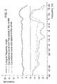
- Figure 3 shows the rejection curve of one capsule of a sound field microphone with and without the body incorporated in the interior and the 0 degree frequency range; a thin line, which runs close to 0 dB over almost the entire frequency range, represents a 0 degree curve, which is the curve for the entry of sound from the direction in which the microphone has the greatest sensitivity.
- the rejection curve of that capsule according to the prior art is more strongly emphasized and provided with two pronounced local minima; the rejection curve of the same capsule is even more strongly emphasized, with only one local minimum lying at higher frequencies, after incorporation of a sphere made of silicone (Elastil) with a volume fraction of 34% (in reference to the aforementioned virtual tetrahedron) in the interior of said soundfield microphone, with which the first-named rejection curve was determined.
- silicone silicone
- rejection of the capsule according to the prior art is better at frequencies to just below 6 kHz than in the capsule according to the invention, from the intersection point of the two curves at this frequency; rejection of the capsule equipped according to the invention is stronger, and remains so, below -10 dB.
- this reduction is much more important than the loss of rejection in the low-frequency range, since the differences between -16 dB and -22 or -24 dB are by far not nearly as serious for the hearing experience than the difference of between about -8 or -12 dB, i.e., the attainable gain according to the invention is about 10 kHz.
- the invention is not only restricted to the depicted and described practical example, but can be modified in different ways.
- the annular membrane mounts which, during actual design of the sound field microphone, also hold it together since they carry elements provided for this purpose, with the sound-entry openings being on its outer surface, which lead to the back side of the corresponding membrane.
- the spherically flattened element introduced into the interior of the sound field microphone with corresponding annular seats that accommodate the inner edges of the mounting rings, or to support it against them, and thus to position and secure the introduced solid body without requiring further measures.
- the body referred to as "spherically flattened” has essentially the shape of an element that forms when an air balloon is inflated in the center, until it finally touches the back sides of the capsules over the entire surface and swells a little between the capsules. If such an element is viewed as solidified, from each capsule it acquires a circular impression with an annular shoulder on its surface. If, under practical conditions, the contact surface on the inside wall of the capsule is “freely worked” (because of tolerances, vibrations, weight, etc.), one “annular seat” per capsule is formed on the body.
- the body is then no longer spherical in the gussets between the capsules, but is tetrahedral; its volume can be much greater than the aforementioned 40%, and up to 65%, of the volume of the virtual tetrahedron. It is understandable that the sound-entry openings for the back side of the membrane of the capsules must remain free of the spherically flattened element so formed.
- the sphere it is therefore also possible for the sphere to press against all force systems from the back, which is advantageous for purposes of tolerance compensation during assembly of the capsules since, in the prior art, components for this purpose that are either elastic or that have a thread are necessary. These components can be eliminated by the use of an elastic sphere, since the sphere presses the capsule elements together.
- the seats are unnecessary when the spherical diameter is adjusted due to the geometry of the sound field microphone, and especially due to the position and size of the internal edges of the membrane mounting rings of the individual capsules, so that the incorporated sphere is held by these rings.
- This is readily possible, in particular, when the material of the introduced body, has a certain elasticity, for example, when it consists of elastomer material. The mechanical design can therefore be simplified.
- the volume of the solid body 8 in relation to the volume of the regular polyhedron can be carried out also for sound field microphones comprising more than four capsules arranged on the surfaces of a hexahedron, octahedron, dodecahedron, etc....
- the solid body 8 is a sphere and arranged in the center of a dodecahedron. It could be shown, that in any case the volume of the solid body 8 has to be at least 1% of the volume of the regular polyhedron in order to achieve advantageous effects according to the invention.
Landscapes
- Physics & Mathematics (AREA)
- Engineering & Computer Science (AREA)
- Acoustics & Sound (AREA)
- Signal Processing (AREA)
- Circuit For Audible Band Transducer (AREA)
- Details Of Audible-Bandwidth Transducers (AREA)
- Obtaining Desirable Characteristics In Audible-Bandwidth Transducers (AREA)
Abstract
Description
- The invention concerns a sound field microphone, comprising at least four individual pressure-gradient microphones, subsequently called simply capsules, whose back sides are arranged in space on tangential surfaces of an imaginary sphere with the largest possible symmetry, i.e. on the surfaces of a virtual essentially regular polyhedron, i.e., in the case of four capsules, on the faces of a tetrahedron.
- Such sound field microphones were first described in
GB 1 512 514 AUS 4,042,779 A corresponding to this document, which is included in the disclosure of the present invention as a reference. This involves a microphone consisting of four pressure-gradient capsules in which the individual capsules are arranged in a tetrahedron, so that the membranes of the individual capsules are essentially parallel to the imaginary surfaces of the tetrahedron. Each of these individual capsules delivers its own signal A, B, C, or D. Each individual pressure receiver has a directivity pattern deviating from the omni, which can approximately be represented in the form (1 - k) + k x cos(θ), in which θ denotes the azimuth under which the capsule is exposed to sound and the ratio factor k designates how strongly the signal deviates from an omnidirectional signal (in a sphere, k = 0; in a figure-eight, k = 1). The signals of the individual capsules are denoted A, B, C, and D. The axis of symmetry of the directivity pattern of each individual microphone is perpendicular to the membrane or to the corresponding face of the tetrahedron. The axes of symmetry of the directivity pattern of each individual capsule (also called the main direction of the individual capsule) therefore together enclose an angle of about 109.5°. According to the calculation procedure in the above patent, the four individual capsule signals are now converted to the so-called B format (W, X, Y, Z). The calculation procedure is:


- The directivity of the forming signals are described essentially by means of spherical harmonics. The signals include one sphere (W) and three figure-eights (X, Y, Z) orthogonal to each other. Such a sound field microphone is therefore also called first-order sound field microphone (creating signals with spherical harmonics up to the first order).
- A second-order sound field microphone is considered below. This type of microphone is treated for example, in the dissertation "On the Theory of the Second-Order Sound Field Microphone" by Philip S. Cotterell, BSc, MSc, AMIEE, Department of Cybernetics, February 2002.
- The sound field microphone that can image the spherical harmonics up to the second order requires, for example, twelve individual gradient microphone capsules which, as shown in Figure 4, are arranged in the form of a dodecahedron in which each face carries a capsule. The numbering of the capsules begins on the front side of the top with "a" and ends at the right bottom with "1". For an understanding of the following formulas, a Cartesian coordinate system was used as a basis, in which the normal vectors of the individual capsules are defined as follows.
If two auxiliary quantities are introduced:

these normal vectors û can be written simply:


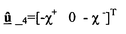


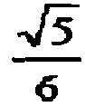
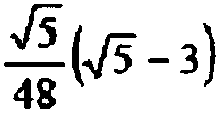
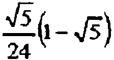
- The B format with the known zero-th and first-order signals W, X, Y, Z must now be expanded by additional signals corresponding to the second-order spherical signal components. These five signals are denoted with the letters R, S, T, U, and V. The relations between the capsules signals s1, s1 ... s12 with the corresponding signals W, X, Y, Z, R, S, T, U, and V is shown in the following table.
Table: W X Y Z R S T U V s1 

0 

0 
0 s2 

0 


0 
0 s3 

0 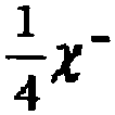

0 
0 s4 

0 


0 
0 s5 


0 
0 0 

s6 


0 
0 0 

s7 


0 
0 0 

s8 


0 
0 0 

s9 
0 


0 
0 s10 
0 


0 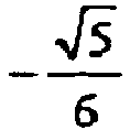

0 s11 
0 


0 

0 s12 
0 


0 

0 - The major advantage of the sound field microphone is that after recording of the sound events recorded by the capsules, it is possible to alter the directivity patterns of the entire microphone by corresponding deduction of individual signals, and therefore adapting it in the desired manner even during playback or final production of the sound carrier. It is possible, for example, to emphasize, in particular, the corresponding soloists of an ensemble, to mask unexpected or undesired sound events by influencing the directivity patterns, or to follow a moving sound source (for example, an actor on the stage), so that the recording quality is always retained, regardless of the changed position of the sound source.
- A noticeable effect is exerted by the physical presence of the capsules on the considered capsule or on the signals received by this capsule: the employed gradient capsules only react to the difference in sound pressure between the front of the membrane and the back of the membrane, for which reason if sound encounters the microphone from a precisely localizable, small-space sound source, this difference depends, among other things, on the different path of the sound waves to the front side and back side and the different travel times of the sound. Since the capsules in the sound field microphone are close and adjacent to each other, because of the requirement of keeping the total size of the sound field microphone as small as possible, an adverse effect of sound entry on the back side occurs (in this description and in the claims, the sides of the membranes facing the center of the sphere of the ensemble, by definition) so that there are changes in the output signal, in comparison with the output signal of a capsule arranged at precisely the same location, but without the other capsules of the sound field microphone.
- This means that the cavity formed in the interior of the microphone arrangement (i.e., that of the capsules) and naturally its delimitation by said microphone arrangement, together with its mounting devices, etc., acts as an acoustic filter, which adds to the usual acoustic filtering by the sound paths that lead to the back side of the membrane of the individual capsules (these sound paths pertain to the inner life of a capsule and therefore their role depends on the nature of the capsule mount). The effect of this additional acoustic filter is frequency-dependent and has the strongest effect at frequencies at which the wavelength of the sound is essentially the same order of magnitude as the dimensions of the membrane and the dimensions of the entire sound field microphone. In the now employed sound field microphones, this strong effect lies essentially in the frequency ranges around 10 kHz, at which rejection, i.e., the frequency response from the direction from which the individual capsule is least sensitive, is weakest and, in most cases, drops below 10 dB.
- It is therefore the task of the invention--in a sound field microphone, especially one with four individual capsules and a tetrahedral arrangement--to keep rejection, i.e., cancellation of the output signal during sound exposure from directions in which the individual microphones have the least sensitivity, as uniform as possible over the frequency range, and especially stronger than 10 dB in all ranges between 20 Hz to 20 kHz.
- These objectives are achieved according to the invention by the fact that in the interior of the virtual polyhedron, a solid body is arranged, whose volume is greater than 1% of the volume of virtual polyhedron. According to the description and the claim, the property "solid" is to be understood to mean--not special mechanical properties, such as hard or seamless or the like--but only as a contrast to liquid or gaseous, and is to be understood in the broadest sense.
- The invention is further explained below with reference to drawings. In the drawings:
- Figure 1 depicts, purely schematically, the geometric arrangement of the microphone, according to the invention, in a side view,
- Figure 2 shows the arrangement in a top view, and
- Figure 3 shows the effect of the expedients on the signal according to the invention,
- Figure 4 shows the arrangement of the capsules in a second-order sound field microphone.
- As is apparent from Figure 1, a sound field microphone consists of four
cylindrical capsules 2, aligned spatially symmetric, i.e., in a tetrahedral arrangement. The inclusion of sound openings (openings for the release of sound), mounting elements, connection wires, mounts, etc., was deliberately omitted in this depiction, in order to clearly emphasize the essence of the invention. - A second order sound field microphone is shown in Fig. 4 with twelve capsules a, b, c, d, e, f, g, h, i, j, k, l aligned spatially symmetric in an dodecahedral arrangement. The inventive concept can be applied to any kind of sound field microphone, whose capsules are arranged on a virtual essentially regular polyhedron, e.g. tetrahedron, hexahedron, octahedron, dodecahedron, etc. with a corresponding number of capsules (four, six, eight, twelve, etc....). In the following the invention will be discussed considering a tetrahedral arrangement of four capsules. It will be obvious, that these considerations can be extended to all kind of sound field microphones.
- A common feature of all tetrahedral arrangements of
capsules 2 is the fact that two individual capsules are in contact at acontact point 3. If one now imagines avirtual tetrahedron 4 in the capsule arrangement, in which thosecontact points 3 of twocapsules 2 form the bisection point of atetrahedral edge 5, an assertion can be made concerning the size of the solid to be introduced: - If one imagines, in this virtual tetrahedron, the largest
possible sphere 7 to be inscribed, shown with a dashed line in Figure 1, which is bound by the side surfaces, the following indicates the volume of thissphere 7 relative to the volume of the virtual tetrahedron 4:
or, expressed in numbers: the volume ofsphere 7 is 30.2% of the volume ofvirtual tetrahedron 4. If a sphere of this size is introduced as a solid into the interior of the capsule arrangement, thissphere 7 touches the center of the back side of each of theindividual capsules 2. If the sound inputs on the back side of the rotationally symmetric individual capsules are situated radially farther from the center or on the surface, they are not covered by the sphere. With further enlargement of the sphere, accompanied by flattening at each contact surface with a capsule, these sound inputs are increasingly influenced, until they are finally covered, so that the individual capsule can therefore no longer function as a pressure-gradient transducer. - As an upper limit, in reference to the
virtual tetrahedron 4, a volume limitation of the introducedsolid body 8 can be set at a maximum of 30.2%, as long as it is a complete sphere, or a maximum of 40%, as long as it is considered essentially spherical. For the spherically flattened form described further below, a maximum of 65% is estimated. For the lower limit, it is critical that the effect becomes increasingly negligible with a diminishing size of the solid body. A sphere with a third of the diameter of the one just inscribed, touching the tetrahedron at points, will still only influence the sound field in very restricted fashion. According to the above-mentioned ratio calculation for the upper limit, the reduction of the spherical diameter to a third means a reduction of the volume of the sphere to 3%; with reference to the virtual tetrahedron, it means a reduction to 1% of its volume! The spherical solid body being incorporated can therefore be formed within its volume limits, namely, in the spherical shape, at 1% to 40% of the volume of thevirtual tetrahedron 4 formed by the capsule arrangement, and at 65% in the case of a spherically flattened solid body. - It has surprisingly been shown that the nature of the solid body introduced into the cavity can be chosen over broad limits and the desired goal is always reached. The introduced object can consist of plastic, both elastomeric material as well as rubber-like material, but also metal, ceramic, glass, or wood, in which the surface roughness has no serious effect. Porous materials (foam) have no effect.
- The shape of a sphere has proven to be suitable for incorporation since, in this case, the orientation in the interior of the essentially tetrahedral cavity is meaningless and errors during positioning have turned out to have no effect on the result over a wide range.
- Figure 3 shows the rejection curve of one capsule of a sound field microphone with and without the body incorporated in the interior and the 0 degree frequency range; a thin line, which runs close to 0 dB over almost the entire frequency range, represents a 0 degree curve, which is the curve for the entry of sound from the direction in which the microphone has the greatest sensitivity. The rejection curve of that capsule according to the prior art is more strongly emphasized and provided with two pronounced local minima; the rejection curve of the same capsule is even more strongly emphasized, with only one local minimum lying at higher frequencies, after incorporation of a sphere made of silicone (Elastil) with a volume fraction of 34% (in reference to the aforementioned virtual tetrahedron) in the interior of said soundfield microphone, with which the first-named rejection curve was determined.
- As follows from the figure, rejection of the capsule according to the prior art is better at frequencies to just below 6 kHz than in the capsule according to the invention, from the intersection point of the two curves at this frequency; rejection of the capsule equipped according to the invention is stronger, and remains so, below -10 dB. Here, it should be pointed out, in particular, that this reduction is much more important than the loss of rejection in the low-frequency range, since the differences between -16 dB and -22 or -24 dB are by far not nearly as serious for the hearing experience than the difference of between about -8 or -12 dB, i.e., the attainable gain according to the invention is about 10 kHz.
- The invention is not only restricted to the depicted and described practical example, but can be modified in different ways. For example, it is possible to provide the annular membrane mounts, which, during actual design of the sound field microphone, also hold it together since they carry elements provided for this purpose, with the sound-entry openings being on its outer surface, which lead to the back side of the corresponding membrane. It is also possible to equip the spherically flattened element introduced into the interior of the sound field microphone with corresponding annular seats that accommodate the inner edges of the mounting rings, or to support it against them, and thus to position and secure the introduced solid body without requiring further measures.
- The body referred to as "spherically flattened" has essentially the shape of an element that forms when an air balloon is inflated in the center, until it finally touches the back sides of the capsules over the entire surface and swells a little between the capsules. If such an element is viewed as solidified, from each capsule it acquires a circular impression with an annular shoulder on its surface. If, under practical conditions, the contact surface on the inside wall of the capsule is "freely worked" (because of tolerances, vibrations, weight, etc.), one "annular seat" per capsule is formed on the body. The body is then no longer spherical in the gussets between the capsules, but is tetrahedral; its volume can be much greater than the aforementioned 40%, and up to 65%, of the volume of the virtual tetrahedron. It is understandable that the sound-entry openings for the back side of the membrane of the capsules must remain free of the spherically flattened element so formed.
- It is therefore also possible for the sphere to press against all force systems from the back, which is advantageous for purposes of tolerance compensation during assembly of the capsules since, in the prior art, components for this purpose that are either elastic or that have a thread are necessary. These components can be eliminated by the use of an elastic sphere, since the sphere presses the capsule elements together.
- When the incorporated body has a spherical shape, the seats are unnecessary when the spherical diameter is adjusted due to the geometry of the sound field microphone, and especially due to the position and size of the internal edges of the membrane mounting rings of the individual capsules, so that the incorporated sphere is held by these rings. This is readily possible, in particular, when the material of the introduced body, has a certain elasticity, for example, when it consists of elastomer material. The mechanical design can therefore be simplified.
- It has to mentioned that similar considerations concerning the volume of the
solid body 8 in relation to the volume of the regular polyhedron can be carried out also for sound field microphones comprising more than four capsules arranged on the surfaces of a hexahedron, octahedron, dodecahedron, etc.... In Fig. 4 thesolid body 8 is a sphere and arranged in the center of a dodecahedron. It could be shown, that in any case the volume of thesolid body 8 has to be at least 1% of the volume of the regular polyhedron in order to achieve advantageous effects according to the invention.
Claims (8)
- Sound field microphone, comprising at least four individual pressure-gradient microphones, called capsules (2, a, b, c, d, e, f, g, h, i, j, k, l), whose back sides are arranged in space on tangential surfaces of an imaginary sphere with the largest possible symmetry, i.e. on the surfaces of a virtual essentially regular polyhedron, characterized by the fact that in the interior of the virtual polyhedron (4), a solid body (8) is arranged, whose volume is greater than 1% of the volume of virtual polyhedron (4).
- Sound field microphone according to Claim 1, characterized in that the microphone comprises four capsules (2), whose back sides are arranged in space on the surfaces of a virtual tetrahedron (4).
- Microphone according to Claim 1 or 2, characterized by the fact that the solid body (8) is essentially spherical and has a maximum of 40% of the volume of the virtual polyhedron (4).
- Microphone according to Claim 3, characterized by the fact that the solid body (8) is essentially spherically flattened and has a maximum of 65% of the volume of the virtual polyhedron (4).
- Microphone according to on of Claims 1 to 4, characterized by the fact that the solid body (8) fills up the space of the virtual polyhedron (4) in the area between capsules (2, a, b, c, d, e, f, g, h, i, j, k, l).
- Microphone according to on of Claims 1 to 5, characterized by the fact that the capsules (2) lie against solid body (8), at least along an annular surface.
- Microphone according to one of Claims 1 to 6, characterized by the fact that the solid body (8) has positioning elements for capsules (2, a, b, c, d, e, f, g, h, i, j, k, l).
- Microphone according to one of Claims 1 to 7, characterized by the fact that the solid body (8) consists of silicone or an elastomer plastic.
Priority Applications (4)
| Application Number | Priority Date | Filing Date | Title |
|---|---|---|---|
| AT05450110T ATE545286T1 (en) | 2005-06-23 | 2005-06-23 | SOUND FIELD MICROPHONE |
| EP05450110A EP1737268B1 (en) | 2005-06-23 | 2005-06-23 | Sound field microphone |
| JP2006133134A JP2007006458A (en) | 2005-06-23 | 2006-05-11 | Sound field microphone |
| US11/474,124 US20070009116A1 (en) | 2005-06-23 | 2006-06-23 | Sound field microphone |
Applications Claiming Priority (1)
| Application Number | Priority Date | Filing Date | Title |
|---|---|---|---|
| EP05450110A EP1737268B1 (en) | 2005-06-23 | 2005-06-23 | Sound field microphone |
Publications (2)
| Publication Number | Publication Date |
|---|---|
| EP1737268A1 true EP1737268A1 (en) | 2006-12-27 |
| EP1737268B1 EP1737268B1 (en) | 2012-02-08 |
Family
ID=35134502
Family Applications (1)
| Application Number | Title | Priority Date | Filing Date |
|---|---|---|---|
| EP05450110A Expired - Lifetime EP1737268B1 (en) | 2005-06-23 | 2005-06-23 | Sound field microphone |
Country Status (4)
| Country | Link |
|---|---|
| US (1) | US20070009116A1 (en) |
| EP (1) | EP1737268B1 (en) |
| JP (1) | JP2007006458A (en) |
| AT (1) | ATE545286T1 (en) |
Cited By (9)
| Publication number | Priority date | Publication date | Assignee | Title |
|---|---|---|---|---|
| WO2009062212A1 (en) * | 2007-11-13 | 2009-05-22 | Akg Acoustics Gmbh | Microphone arrangement comprising three pressure gradient transducers |
| WO2009062210A1 (en) * | 2007-11-13 | 2009-05-22 | Akg Acoustics Gmbh | Microphone arrangement |
| WO2009062214A1 (en) * | 2007-11-13 | 2009-05-22 | Akg Acoustics Gmbh | Method for synthesizing a microphone signal |
| WO2009062213A1 (en) * | 2007-11-13 | 2009-05-22 | Akg Acoustics Gmbh | Microphone arrangement, having two pressure gradient transducers |
| WO2009062211A1 (en) * | 2007-11-13 | 2009-05-22 | Akg Acoustics Gmbh | Position determination of sound sources |
| ITUD20090183A1 (en) * | 2009-10-14 | 2011-04-15 | Advanced Ind Design In Acous Tic Srl | PROBE FOR VECTOR UNDERWATER MEASUREMENTS OF SOUND FIELD |
| CN102271301A (en) * | 2011-06-29 | 2011-12-07 | 陈奚平 | a speaker |
| US8345898B2 (en) | 2008-02-26 | 2013-01-01 | Akg Acoustics Gmbh | Transducer assembly |
| EP3007461A1 (en) * | 2014-10-10 | 2016-04-13 | Harman Becker Automotive Systems GmbH | Microphone array |
Families Citing this family (31)
| Publication number | Priority date | Publication date | Assignee | Title |
|---|---|---|---|---|
| EP1737265A1 (en) * | 2005-06-23 | 2006-12-27 | AKG Acoustics GmbH | Determination of the position of sound sources |
| GB0619825D0 (en) * | 2006-10-06 | 2006-11-15 | Craven Peter G | Microphone array |
| JP5304293B2 (en) * | 2009-02-10 | 2013-10-02 | ヤマハ株式会社 | Sound collector |
| DE102009032057A1 (en) * | 2009-07-07 | 2011-01-20 | Siemens Aktiengesellschaft | Pressure wave recording and playback |
| JP5249901B2 (en) * | 2009-10-15 | 2013-07-31 | ホシデン株式会社 | Condenser microphone |
| US9554207B2 (en) | 2015-04-30 | 2017-01-24 | Shure Acquisition Holdings, Inc. | Offset cartridge microphones |
| US9565493B2 (en) | 2015-04-30 | 2017-02-07 | Shure Acquisition Holdings, Inc. | Array microphone system and method of assembling the same |
| CN106454616B (en) * | 2016-08-29 | 2019-10-08 | 陈立康 | Holographic three-dimensional sound system |
| US10367948B2 (en) | 2017-01-13 | 2019-07-30 | Shure Acquisition Holdings, Inc. | Post-mixing acoustic echo cancellation systems and methods |
| US10595146B2 (en) * | 2017-12-21 | 2020-03-17 | Verizon Patent And Licensing Inc. | Methods and systems for extracting location-diffused ambient sound from a real-world scene |
| EP3804356A1 (en) | 2018-06-01 | 2021-04-14 | Shure Acquisition Holdings, Inc. | Pattern-forming microphone array |
| US11297423B2 (en) | 2018-06-15 | 2022-04-05 | Shure Acquisition Holdings, Inc. | Endfire linear array microphone |
| US11310596B2 (en) | 2018-09-20 | 2022-04-19 | Shure Acquisition Holdings, Inc. | Adjustable lobe shape for array microphones |
| TWI865506B (en) | 2019-03-21 | 2024-12-11 | 美商舒爾獲得控股公司 | Auto focus, auto focus within regions, and auto placement of beamformed microphone lobes with inhibition functionality |
| EP3942842B1 (en) | 2019-03-21 | 2026-03-11 | Shure Acquisition Holdings, Inc. | Housings and associated design features for ceiling array microphones |
| US11558693B2 (en) | 2019-03-21 | 2023-01-17 | Shure Acquisition Holdings, Inc. | Auto focus, auto focus within regions, and auto placement of beamformed microphone lobes with inhibition and voice activity detection functionality |
| EP3948859B1 (en) * | 2019-04-12 | 2024-10-16 | Huawei Technologies Co., Ltd. | Device and method for obtaining a first order ambisonic signal |
| CN114051738B (en) | 2019-05-23 | 2024-10-01 | 舒尔获得控股公司 | Steerable speaker array, system and method thereof |
| CN114051637B (en) | 2019-05-31 | 2025-10-28 | 舒尔获得控股公司 | Low-latency automatic mixer with integrated voice and noise activity detection |
| WO2021041275A1 (en) | 2019-08-23 | 2021-03-04 | Shore Acquisition Holdings, Inc. | Two-dimensional microphone array with improved directivity |
| WO2021087377A1 (en) | 2019-11-01 | 2021-05-06 | Shure Acquisition Holdings, Inc. | Proximity microphone |
| US11552611B2 (en) | 2020-02-07 | 2023-01-10 | Shure Acquisition Holdings, Inc. | System and method for automatic adjustment of reference gain |
| WO2021243368A2 (en) | 2020-05-29 | 2021-12-02 | Shure Acquisition Holdings, Inc. | Transducer steering and configuration systems and methods using a local positioning system |
| JP7814400B2 (en) | 2021-01-28 | 2026-02-16 | シュアー アクイジッション ホールディングス インコーポレイテッド | Hybrid Audio Beamforming System |
| US12452584B2 (en) | 2021-01-29 | 2025-10-21 | Shure Acquisition Holdings, Inc. | Scalable conferencing systems and methods |
| US12542123B2 (en) | 2021-08-31 | 2026-02-03 | Shure Acquisition Holdings, Inc. | Mask non-linear processor for acoustic echo cancellation |
| US12289584B2 (en) | 2021-10-04 | 2025-04-29 | Shure Acquisition Holdings, Inc. | Networked automixer systems and methods |
| US12525083B2 (en) | 2021-11-05 | 2026-01-13 | Shure Acquisition Holdings, Inc. | Distributed algorithm for automixing speech over wireless networks |
| US12250526B2 (en) | 2022-01-07 | 2025-03-11 | Shure Acquisition Holdings, Inc. | Audio beamforming with nulling control system and methods |
| US12598261B2 (en) | 2022-09-28 | 2026-04-07 | Shure Acquisition Holdings, Inc. | Wideband doubletalk detection for optimization of acoustic echo cancellation |
| USD1056882S1 (en) * | 2023-03-07 | 2025-01-07 | Logitech Europe S.A. | Microphone |
Citations (4)
| Publication number | Priority date | Publication date | Assignee | Title |
|---|---|---|---|---|
| US4042779A (en) | 1974-07-12 | 1977-08-16 | National Research Development Corporation | Coincident microphone simulation covering three dimensional space and yielding various directional outputs |
| EP0374902A2 (en) * | 1988-12-21 | 1990-06-27 | Bschorr, Oskar, Dr. rer. nat. | Microphone system for determining the direction and position of a sound source |
| EP0869697A2 (en) * | 1997-04-03 | 1998-10-07 | Lucent Technologies Inc. | A steerable and variable first-order differential microphone array |
| US20030209383A1 (en) * | 2002-03-01 | 2003-11-13 | Charles Whitman Fox | Modular microphone array for surround sound recording |
Family Cites Families (12)
| Publication number | Priority date | Publication date | Assignee | Title |
|---|---|---|---|---|
| US4828365A (en) * | 1988-02-22 | 1989-05-09 | Rca Licensing Corporation | Multicolor filter for producing purer white across a display device |
| JP2544173B2 (en) * | 1988-03-17 | 1996-10-16 | 玄 伊達 | Sound receiving device |
| JPH0472525A (en) * | 1990-07-13 | 1992-03-06 | Nippon Telegr & Teleph Corp <Ntt> | Sound source direction distinguishing sensor |
| JP3881092B2 (en) * | 1997-07-10 | 2007-02-14 | シチズン時計株式会社 | LCD panel |
| US6124909A (en) * | 1996-12-25 | 2000-09-26 | Casio Computer Co., Ltd. | Color liquid crystal display device having a plurality of pixel areas which emit non-colored light |
| US6195140B1 (en) * | 1997-07-28 | 2001-02-27 | Sharp Kabushiki Kaisha | Liquid crystal display in which at least one pixel includes both a transmissive region and a reflective region |
| CN1246931A (en) * | 1997-12-04 | 2000-03-08 | 平板展示(Fpd)有限公司 | Display device |
| CN1145069C (en) * | 1998-02-04 | 2004-04-07 | 精工爱普生株式会社 | Liquid crystal device and electronic apparatus |
| EP1072926B1 (en) * | 1999-02-15 | 2003-10-08 | Citizen Watch Co. Ltd. | Liquid-crystal display |
| TW581918B (en) * | 2001-03-07 | 2004-04-01 | Sharp Kk | Transmission/reflection type color liquid crystal display device |
| JP2002343816A (en) * | 2001-05-18 | 2002-11-29 | Lintec Corp | Resin tie bar forming tape, resin tie bar, lead frame with resin tie bar, resin-sealed semiconductor device, and method of manufacturing the same |
| US6734935B2 (en) * | 2001-07-04 | 2004-05-11 | Lg. Philips Lcd Co., Ltd. | Array panel for a transflective liquid crystal display device |
-
2005
- 2005-06-23 EP EP05450110A patent/EP1737268B1/en not_active Expired - Lifetime
- 2005-06-23 AT AT05450110T patent/ATE545286T1/en active
-
2006
- 2006-05-11 JP JP2006133134A patent/JP2007006458A/en active Pending
- 2006-06-23 US US11/474,124 patent/US20070009116A1/en not_active Abandoned
Patent Citations (5)
| Publication number | Priority date | Publication date | Assignee | Title |
|---|---|---|---|---|
| US4042779A (en) | 1974-07-12 | 1977-08-16 | National Research Development Corporation | Coincident microphone simulation covering three dimensional space and yielding various directional outputs |
| GB1512514A (en) | 1974-07-12 | 1978-06-01 | Nat Res Dev | Microphone assemblies |
| EP0374902A2 (en) * | 1988-12-21 | 1990-06-27 | Bschorr, Oskar, Dr. rer. nat. | Microphone system for determining the direction and position of a sound source |
| EP0869697A2 (en) * | 1997-04-03 | 1998-10-07 | Lucent Technologies Inc. | A steerable and variable first-order differential microphone array |
| US20030209383A1 (en) * | 2002-03-01 | 2003-11-13 | Charles Whitman Fox | Modular microphone array for surround sound recording |
Cited By (16)
| Publication number | Priority date | Publication date | Assignee | Title |
|---|---|---|---|---|
| US8472639B2 (en) | 2007-11-13 | 2013-06-25 | Akg Acoustics Gmbh | Microphone arrangement having more than one pressure gradient transducer |
| WO2009062210A1 (en) * | 2007-11-13 | 2009-05-22 | Akg Acoustics Gmbh | Microphone arrangement |
| WO2009062214A1 (en) * | 2007-11-13 | 2009-05-22 | Akg Acoustics Gmbh | Method for synthesizing a microphone signal |
| WO2009062213A1 (en) * | 2007-11-13 | 2009-05-22 | Akg Acoustics Gmbh | Microphone arrangement, having two pressure gradient transducers |
| WO2009062211A1 (en) * | 2007-11-13 | 2009-05-22 | Akg Acoustics Gmbh | Position determination of sound sources |
| CN101874411A (en) * | 2007-11-13 | 2010-10-27 | Akg声学有限公司 | Microphone setup including three pressure gradient transducers |
| CN101911721A (en) * | 2007-11-13 | 2010-12-08 | Akg声学有限公司 | Methods of Synthesizing Microphone Signals |
| EP2262277A1 (en) | 2007-11-13 | 2010-12-15 | AKG Acoustics GmbH | Microphone arrangement |
| WO2009062212A1 (en) * | 2007-11-13 | 2009-05-22 | Akg Acoustics Gmbh | Microphone arrangement comprising three pressure gradient transducers |
| CN101911721B (en) * | 2007-11-13 | 2014-04-23 | Akg声学有限公司 | Method for synthesizing a microphone signal |
| US8345898B2 (en) | 2008-02-26 | 2013-01-01 | Akg Acoustics Gmbh | Transducer assembly |
| ITUD20090183A1 (en) * | 2009-10-14 | 2011-04-15 | Advanced Ind Design In Acous Tic Srl | PROBE FOR VECTOR UNDERWATER MEASUREMENTS OF SOUND FIELD |
| CN102271301B (en) * | 2011-06-29 | 2014-02-12 | 陈奚平 | a speaker |
| CN102271301A (en) * | 2011-06-29 | 2011-12-07 | 陈奚平 | a speaker |
| EP3007461A1 (en) * | 2014-10-10 | 2016-04-13 | Harman Becker Automotive Systems GmbH | Microphone array |
| EP3506650A1 (en) | 2014-10-10 | 2019-07-03 | Harman Becker Automotive Systems GmbH | Microphone array |
Also Published As
| Publication number | Publication date |
|---|---|
| JP2007006458A (en) | 2007-01-11 |
| EP1737268B1 (en) | 2012-02-08 |
| US20070009116A1 (en) | 2007-01-11 |
| ATE545286T1 (en) | 2012-02-15 |
Similar Documents
| Publication | Publication Date | Title |
|---|---|---|
| EP1737268B1 (en) | Sound field microphone | |
| EP1737267B1 (en) | Modelling of a microphone | |
| US2403692A (en) | Piezoelectric device | |
| EP2773131B1 (en) | Spherical microphone array | |
| US4257325A (en) | Mouting of a substantially planar diaphragm defining a sound transducer | |
| US8073186B2 (en) | Loudspeaker | |
| KR101139098B1 (en) | Loudspeaker with undulated membrane | |
| CN110800317B (en) | Micro-electro-mechanical system motor and microphone | |
| KR20170132180A (en) | Dual diaphragm microphone | |
| US20060090955A1 (en) | Microphone diaphragms defined by logarithmic curves and microphones for use therewith | |
| CN104737553A (en) | Porous cover structures for mobile device audio | |
| JP2009540651A (en) | Acoustic device and manufacturing method thereof | |
| KR20140091602A (en) | Bone conduction speaker and compound vibration device thereof | |
| US4284167A (en) | Sound reproducing device | |
| US8208679B2 (en) | Transducer membrane with symmetrical curvature | |
| US11997450B2 (en) | Audio systems, devices, and methods | |
| CN101874411A (en) | Microphone setup including three pressure gradient transducers | |
| TW202402066A (en) | A type of loudspeaker | |
| US9800978B2 (en) | Audio driver assemblies, headphones including the audio driver assemblies, and related methods | |
| CN113596655A (en) | Elastic sheet and bone conduction sound production device | |
| EP2291004A1 (en) | Loudspeaker | |
| CN1462567A (en) | Electroacoustic transducer | |
| JPS6117662Y2 (en) | ||
| CN117426108A (en) | Vibration sensor | |
| JPH04503739A (en) | diaphragm system |
Legal Events
| Date | Code | Title | Description |
|---|---|---|---|
| PUAI | Public reference made under article 153(3) epc to a published international application that has entered the european phase |
Free format text: ORIGINAL CODE: 0009012 |
|
| AK | Designated contracting states |
Kind code of ref document: A1 Designated state(s): AT BE BG CH CY CZ DE DK EE ES FI FR GB GR HU IE IS IT LI LT LU MC NL PL PT RO SE SI SK TR |
|
| AX | Request for extension of the european patent |
Extension state: AL BA HR LV MK YU |
|
| 17P | Request for examination filed |
Effective date: 20070627 |
|
| AKX | Designation fees paid |
Designated state(s): AT BE BG CH CY CZ DE DK EE ES FI FR GB GR HU IE IS IT LI LT LU MC NL PL PT RO SE SI SK TR |
|
| 17Q | First examination report despatched |
Effective date: 20110328 |
|
| GRAP | Despatch of communication of intention to grant a patent |
Free format text: ORIGINAL CODE: EPIDOSNIGR1 |
|
| GRAS | Grant fee paid |
Free format text: ORIGINAL CODE: EPIDOSNIGR3 |
|
| GRAA | (expected) grant |
Free format text: ORIGINAL CODE: 0009210 |
|
| AK | Designated contracting states |
Kind code of ref document: B1 Designated state(s): AT BE BG CH CY CZ DE DK EE ES FI FR GB GR HU IE IS IT LI LT LU MC NL PL PT RO SE SI SK TR |
|
| REG | Reference to a national code |
Ref country code: GB Ref legal event code: FG4D |
|
| REG | Reference to a national code |
Ref country code: CH Ref legal event code: EP Ref country code: AT Ref legal event code: REF Ref document number: 545286 Country of ref document: AT Kind code of ref document: T Effective date: 20120215 |
|
| REG | Reference to a national code |
Ref country code: DE Ref legal event code: R096 Ref document number: 602005032583 Country of ref document: DE Effective date: 20120405 |
|
| REG | Reference to a national code |
Ref country code: NL Ref legal event code: VDEP Effective date: 20120208 |
|
| LTIE | Lt: invalidation of european patent or patent extension |
Effective date: 20120208 |
|
| PG25 | Lapsed in a contracting state [announced via postgrant information from national office to epo] |
Ref country code: LT Free format text: LAPSE BECAUSE OF FAILURE TO SUBMIT A TRANSLATION OF THE DESCRIPTION OR TO PAY THE FEE WITHIN THE PRESCRIBED TIME-LIMIT Effective date: 20120208 Ref country code: IS Free format text: LAPSE BECAUSE OF FAILURE TO SUBMIT A TRANSLATION OF THE DESCRIPTION OR TO PAY THE FEE WITHIN THE PRESCRIBED TIME-LIMIT Effective date: 20120608 Ref country code: NL Free format text: LAPSE BECAUSE OF FAILURE TO SUBMIT A TRANSLATION OF THE DESCRIPTION OR TO PAY THE FEE WITHIN THE PRESCRIBED TIME-LIMIT Effective date: 20120208 |
|
| PGFP | Annual fee paid to national office [announced via postgrant information from national office to epo] |
Ref country code: DE Payment date: 20120627 Year of fee payment: 8 |
|
| PG25 | Lapsed in a contracting state [announced via postgrant information from national office to epo] |
Ref country code: FI Free format text: LAPSE BECAUSE OF FAILURE TO SUBMIT A TRANSLATION OF THE DESCRIPTION OR TO PAY THE FEE WITHIN THE PRESCRIBED TIME-LIMIT Effective date: 20120208 Ref country code: GR Free format text: LAPSE BECAUSE OF FAILURE TO SUBMIT A TRANSLATION OF THE DESCRIPTION OR TO PAY THE FEE WITHIN THE PRESCRIBED TIME-LIMIT Effective date: 20120509 Ref country code: PT Free format text: LAPSE BECAUSE OF FAILURE TO SUBMIT A TRANSLATION OF THE DESCRIPTION OR TO PAY THE FEE WITHIN THE PRESCRIBED TIME-LIMIT Effective date: 20120608 Ref country code: BE Free format text: LAPSE BECAUSE OF FAILURE TO SUBMIT A TRANSLATION OF THE DESCRIPTION OR TO PAY THE FEE WITHIN THE PRESCRIBED TIME-LIMIT Effective date: 20120208 Ref country code: PL Free format text: LAPSE BECAUSE OF FAILURE TO SUBMIT A TRANSLATION OF THE DESCRIPTION OR TO PAY THE FEE WITHIN THE PRESCRIBED TIME-LIMIT Effective date: 20120208 |
|
| PGFP | Annual fee paid to national office [announced via postgrant information from national office to epo] |
Ref country code: GB Payment date: 20120625 Year of fee payment: 8 Ref country code: FR Payment date: 20120705 Year of fee payment: 8 |
|
| PG25 | Lapsed in a contracting state [announced via postgrant information from national office to epo] |
Ref country code: CY Free format text: LAPSE BECAUSE OF FAILURE TO SUBMIT A TRANSLATION OF THE DESCRIPTION OR TO PAY THE FEE WITHIN THE PRESCRIBED TIME-LIMIT Effective date: 20120208 |
|
| PG25 | Lapsed in a contracting state [announced via postgrant information from national office to epo] |
Ref country code: EE Free format text: LAPSE BECAUSE OF FAILURE TO SUBMIT A TRANSLATION OF THE DESCRIPTION OR TO PAY THE FEE WITHIN THE PRESCRIBED TIME-LIMIT Effective date: 20120208 Ref country code: DK Free format text: LAPSE BECAUSE OF FAILURE TO SUBMIT A TRANSLATION OF THE DESCRIPTION OR TO PAY THE FEE WITHIN THE PRESCRIBED TIME-LIMIT Effective date: 20120208 Ref country code: CZ Free format text: LAPSE BECAUSE OF FAILURE TO SUBMIT A TRANSLATION OF THE DESCRIPTION OR TO PAY THE FEE WITHIN THE PRESCRIBED TIME-LIMIT Effective date: 20120208 Ref country code: SE Free format text: LAPSE BECAUSE OF FAILURE TO SUBMIT A TRANSLATION OF THE DESCRIPTION OR TO PAY THE FEE WITHIN THE PRESCRIBED TIME-LIMIT Effective date: 20120208 Ref country code: RO Free format text: LAPSE BECAUSE OF FAILURE TO SUBMIT A TRANSLATION OF THE DESCRIPTION OR TO PAY THE FEE WITHIN THE PRESCRIBED TIME-LIMIT Effective date: 20120208 Ref country code: SI Free format text: LAPSE BECAUSE OF FAILURE TO SUBMIT A TRANSLATION OF THE DESCRIPTION OR TO PAY THE FEE WITHIN THE PRESCRIBED TIME-LIMIT Effective date: 20120208 |
|
| PG25 | Lapsed in a contracting state [announced via postgrant information from national office to epo] |
Ref country code: SK Free format text: LAPSE BECAUSE OF FAILURE TO SUBMIT A TRANSLATION OF THE DESCRIPTION OR TO PAY THE FEE WITHIN THE PRESCRIBED TIME-LIMIT Effective date: 20120208 Ref country code: IT Free format text: LAPSE BECAUSE OF FAILURE TO SUBMIT A TRANSLATION OF THE DESCRIPTION OR TO PAY THE FEE WITHIN THE PRESCRIBED TIME-LIMIT Effective date: 20120208 |
|
| PLBE | No opposition filed within time limit |
Free format text: ORIGINAL CODE: 0009261 |
|
| STAA | Information on the status of an ep patent application or granted ep patent |
Free format text: STATUS: NO OPPOSITION FILED WITHIN TIME LIMIT |
|
| 26N | No opposition filed |
Effective date: 20121109 |
|
| PG25 | Lapsed in a contracting state [announced via postgrant information from national office to epo] |
Ref country code: MC Free format text: LAPSE BECAUSE OF NON-PAYMENT OF DUE FEES Effective date: 20120630 |
|
| REG | Reference to a national code |
Ref country code: CH Ref legal event code: PL |
|
| REG | Reference to a national code |
Ref country code: CH Ref legal event code: PL |
|
| REG | Reference to a national code |
Ref country code: DE Ref legal event code: R097 Ref document number: 602005032583 Country of ref document: DE Effective date: 20121109 |
|
| REG | Reference to a national code |
Ref country code: IE Ref legal event code: MM4A |
|
| PGFP | Annual fee paid to national office [announced via postgrant information from national office to epo] |
Ref country code: AT Payment date: 20120601 Year of fee payment: 8 |
|
| PG25 | Lapsed in a contracting state [announced via postgrant information from national office to epo] |
Ref country code: IE Free format text: LAPSE BECAUSE OF NON-PAYMENT OF DUE FEES Effective date: 20120623 Ref country code: CH Free format text: LAPSE BECAUSE OF NON-PAYMENT OF DUE FEES Effective date: 20120630 Ref country code: ES Free format text: LAPSE BECAUSE OF FAILURE TO SUBMIT A TRANSLATION OF THE DESCRIPTION OR TO PAY THE FEE WITHIN THE PRESCRIBED TIME-LIMIT Effective date: 20120519 Ref country code: LI Free format text: LAPSE BECAUSE OF NON-PAYMENT OF DUE FEES Effective date: 20120630 |
|
| PG25 | Lapsed in a contracting state [announced via postgrant information from national office to epo] |
Ref country code: BG Free format text: LAPSE BECAUSE OF FAILURE TO SUBMIT A TRANSLATION OF THE DESCRIPTION OR TO PAY THE FEE WITHIN THE PRESCRIBED TIME-LIMIT Effective date: 20120508 |
|
| REG | Reference to a national code |
Ref country code: AT Ref legal event code: MM01 Ref document number: 545286 Country of ref document: AT Kind code of ref document: T Effective date: 20130623 |
|
| GBPC | Gb: european patent ceased through non-payment of renewal fee |
Effective date: 20130623 |
|
| REG | Reference to a national code |
Ref country code: FR Ref legal event code: ST Effective date: 20140228 |
|
| REG | Reference to a national code |
Ref country code: DE Ref legal event code: R119 Ref document number: 602005032583 Country of ref document: DE Effective date: 20140101 |
|
| PG25 | Lapsed in a contracting state [announced via postgrant information from national office to epo] |
Ref country code: DE Free format text: LAPSE BECAUSE OF NON-PAYMENT OF DUE FEES Effective date: 20140101 Ref country code: GB Free format text: LAPSE BECAUSE OF NON-PAYMENT OF DUE FEES Effective date: 20130623 Ref country code: TR Free format text: LAPSE BECAUSE OF FAILURE TO SUBMIT A TRANSLATION OF THE DESCRIPTION OR TO PAY THE FEE WITHIN THE PRESCRIBED TIME-LIMIT Effective date: 20120208 |
|
| PG25 | Lapsed in a contracting state [announced via postgrant information from national office to epo] |
Ref country code: LU Free format text: LAPSE BECAUSE OF NON-PAYMENT OF DUE FEES Effective date: 20120623 Ref country code: AT Free format text: LAPSE BECAUSE OF NON-PAYMENT OF DUE FEES Effective date: 20130623 Ref country code: FR Free format text: LAPSE BECAUSE OF NON-PAYMENT OF DUE FEES Effective date: 20130701 |
|
| PG25 | Lapsed in a contracting state [announced via postgrant information from national office to epo] |
Ref country code: HU Free format text: LAPSE BECAUSE OF FAILURE TO SUBMIT A TRANSLATION OF THE DESCRIPTION OR TO PAY THE FEE WITHIN THE PRESCRIBED TIME-LIMIT Effective date: 20050623 |