EP1737148A2 - Laser device for optical packet data transmission in burst mode systems - Google Patents
Laser device for optical packet data transmission in burst mode systems Download PDFInfo
- Publication number
- EP1737148A2 EP1737148A2 EP06020659A EP06020659A EP1737148A2 EP 1737148 A2 EP1737148 A2 EP 1737148A2 EP 06020659 A EP06020659 A EP 06020659A EP 06020659 A EP06020659 A EP 06020659A EP 1737148 A2 EP1737148 A2 EP 1737148A2
- Authority
- EP
- European Patent Office
- Prior art keywords
- laser light
- laser
- packet data
- light source
- power consuming
- Prior art date
- Legal status (The legal status is an assumption and is not a legal conclusion. Google has not performed a legal analysis and makes no representation as to the accuracy of the status listed.)
- Granted
Links
- 230000003287 optical effect Effects 0.000 title claims abstract description 32
- 230000005540 biological transmission Effects 0.000 title claims abstract description 8
- 230000009977 dual effect Effects 0.000 claims abstract description 12
- 230000000295 complement effect Effects 0.000 claims abstract description 9
- 230000004044 response Effects 0.000 claims description 21
- 239000000945 filler Substances 0.000 claims description 7
- 239000013307 optical fiber Substances 0.000 claims description 6
- 230000008901 benefit Effects 0.000 description 3
- 230000008033 biological extinction Effects 0.000 description 3
- 230000008878 coupling Effects 0.000 description 2
- 238000010168 coupling process Methods 0.000 description 2
- 238000005859 coupling reaction Methods 0.000 description 2
- 239000003990 capacitor Substances 0.000 description 1
- 230000001419 dependent effect Effects 0.000 description 1
- 238000001514 detection method Methods 0.000 description 1
- 239000000835 fiber Substances 0.000 description 1
- 230000006872 improvement Effects 0.000 description 1
- 238000000034 method Methods 0.000 description 1
Images


Classifications
-
- H—ELECTRICITY
- H04—ELECTRIC COMMUNICATION TECHNIQUE
- H04B—TRANSMISSION
- H04B10/00—Transmission systems employing electromagnetic waves other than radio-waves, e.g. infrared, visible or ultraviolet light, or employing corpuscular radiation, e.g. quantum communication
- H04B10/50—Transmitters
- H04B10/572—Wavelength control
Definitions
- the invention relates to a laser device for optical packet data transmission in burst mode systems and to an optical transmitter in such a system.
- known laser devices comprise a laser light source for outputting a laser light beam and a laser driver for driving the laser light source.
- the known laser devices further comprise an optical modulator means for receiving the laser light beam output by the laser light source and a packet data source for outputting a packet data stream.
- they comprise a modulated driver for receiving the packet data stream output by the packet data source and for driving or controlling the optical modulator means in response to the packet data stream resulting in that the optical modulator means modulates the laser light beam in response to the packet data stream.
- the optical modulator means presently available on the market suffer from the disadvantage that they are not able to completely close their light output even if they are driven by a shut-off signal, for example represented by a logical zero. This is because they only have a low extinction ratio. Consequently, there remains a residual light which is output by the optical modulator means, for example onto an optical fiber, even if an logical zero shall be transmitted.
- the laser device described above is characterized according to the invention by a filter means for generating an envelope signal of the data packets in the packet data stream; and by a switching means for switching the laser driver in response to the envelope signal.
- the laser source is switched on and off in response to the envelope signal of the data packets of the data stream. In particular, it is switched on when a packet shall be transmitted and it is switched off if no packet is transmitted. Because of the specific architecture of the laser device according to the invention, in particular because of the switching of the laser source a definite switching of the laser beam is achieved. If the laser light source is switched off it does -in contrast to an optical modulator means - definitely not emit any residual laser light. Consequently, in that case also the downstream optical modulator means does not emit any residual laser light in that case.
- the extinction ratio of the laser device according to the invention and in particular of the optical modulator is sufficient high enough, even for being used in burst mode systems.
- filler patterns are provided between packet data in the packet data stream. These filler patterns are provided for making sure that a constant component of the data stream does not vary over the time, in particular not over different time slots. Because the constant component is kept constant, it does not transmit any information and consequently there is no need that the constant component is transmitted correctly. Thus, available low-priced modulator drivers might be used within the laser device, even if they are not able to keep the constant component constant during transmission.
- the laser light source as a dual power consuming unit comprising at least two power consuming elements and to embody the laser driver as differential driver for driving both elements in a complementary manner in response to the envelope signal.
- the laser light source suffers from thermal expansion, if it is switched on and from thermal concentration, if it is switched off.
- the fluctuations of the thermal expansion cause a proportional variation of the distance between two opposing mirrors within the laser light source and thus causing variations in the wavelength of the laser light emitted by the laser light source because the distance of the opposing mirrors is responsible for the wavelength.
- Variations in the wavelength cause problems in the correct detection of a transmitted signal, in particular in wavelength multiplex systems where a plurality of laser devices transmit in particular packet data streams modulated onto different carrier frequencies (wavelengths)via the same channel.
- a plurality of laser devices transmit in particular packet data streams modulated onto different carrier frequencies (wavelengths)via the same channel.
- the laser frequency becomes stable within a time scale compatible with the optical packet duration.
- the above identified object is further solved by another laser device and by an optical transmitter for both of the claimed laser devices.
- the advantages of the solutions correspond to the advantages mentioned above referring to the first claimed laser device.
- FIG. 1 shows a first embodiment of the laser device 100 for optical packet data transmission in a TDM-system, in particular in a DWDM-system according to the invention.
- the laser device comprises a laser light source 130 for outputting a laser light beam and a laser driver 120 for driving the laser light source 130.
- the laser device 100 further comprises an optical modulator means 140 for receiving and modulating the laser light beam output by the laser light source 130.
- the optical modulator means 140 might be connected to an optical fiber 160 and may output the modulated laser light beam onto the fiber.
- the laser device 100 further comprises a packet data source 110 for outputting a packet data stream as shown in Figure 2a).
- the two vertical lines 11, 12 in Figure 2 represent the limits of one time slot; within the time slot the packet data stream comprises a data packet dp as shown in Figure 2b.
- the laser device 100 preferably the packet data source 110, comprises a filter means 112 for generating an envelope signal as shown in Figure 2c of the data packets dp in the packet data stream. Moreover, it comprises a switching means 114 for switching the laser driver 120 in response to the envelope signal.
- the laser driver 120 When switching the laser driver 120 in response to the envelope signal, the laser light source 130 is also switched by the laser driver 120 in response to the envelope signal.
- the envelope signal represents an enabling signal for the laser light source 130. In the case that the laser light source 130 is enabled, the laser light beam, output by the laser light source 130, has a constant high intensity. To the contrary, if the laser light source 130 is disabled by the envelope signal, it does output no light at all.
- the laser device 100 further comprises a modulator driver 150 for receiving the packet data stream according to figure 2a output by the packet data source 110 and for driving or controlling the optical modulator means 140 in response to the packet data stream. This is done in order to enable the optical modulator means 140 to modulate the laser light beam in response to the packet data stream when the laser light source 130 is switched on according to the envelope signal.
- a modulator driver 150 for receiving the packet data stream according to figure 2a output by the packet data source 110 and for driving or controlling the optical modulator means 140 in response to the packet data stream. This is done in order to enable the optical modulator means 140 to modulate the laser light beam in response to the packet data stream when the laser light source 130 is switched on according to the envelope signal.
- the data packet dp within one time slot as shown in Figure 2b has a constant component which does not vary within the time slot.
- a data stream does not only comprise time slots having data packets dp but also comprises an undefined or arbitrary number of gaps between each data packet. Due to the arbitrary number of gaps between the data packets dp within the data stream, the constant component of the data stream varies over time.
- filler patterns fp preferably having an identical constant component like the data packets dp are provided instead of the gaps between data packets dp. Such filler patterns fp are shown in Figure 2a on the right hand side and on the left hand side of the shown time slot comprising the data packet dp.
- the data stream shown in Figure 2a has a constant component which does not vary over time.
- the amount of the constant component is unremarkable and may be ignored because it does not comprise any information.
- the modulator driver 150 must not be embodied to transmit the constant component correctly. This is schematically indicated by the capacitor 155 provided between the packet data source 110 and the modulator driver 150.
- the filler patterns are not modulated by the optical modulator means 140 onto the optical fiber 160, because at the times when they occur in the data stream signal, the laser light source 130 is disabled by the envelope signal.
- the laser device 100 suffers from fluctuations of the thermal expansion of the laser light source 130. These fluctuations are caused by the fact that the laser light source 130 is switched on and off in response to the envelope signal. When it is switched on, its thermal consumption and its thermal expansion are high, whereas during the time when it is switched off it is cooled down and suffers a thermal concentration.
- the resulting thermal fluctuations cause proportional variations in the wavelength of the laser light beam output by the laser light source 130, because the distance between two opposing mirrors within the laser light source 130 responsible for the wavelength varies accordingly. These variations in the wavelength mean variations in the carrier frequency of the transmitted signal and cause problems in correctly detecting information modulated on such carrier frequencies, in particular in systems where different carrier frequencies are transmitted via one channel.
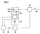
- the second embodiment of the laser device 130' as shown in Figure 3 overcomes the problem by embodying the laser light source 130' as a dual power consuming unit comprising an active laser light source element, for outputting the switched laser light beam as first power consuming element 130'-1 and a second power consuming element 130'-2.
- Those elements preferably have identical electrical parameters and identical thermal losses and both are thermally coupled. They are preferably embodied on one chip.
- the laser driver 120' is embodied as differential driver for driving both power consuming elements 130'-1, 130'-2 in a complementary manner such that the sum of their driving currents is constant in the range of the thermal time constant of the dual power consuming unit.
- the second power consuming element 130'-2 is embodied as blind laser light source element. Contrary to the active laser light source element, the blind laser light source element does not output a laser light beam but just represents a complementary power consuming element.
- Embodying the laser light source 130' in such a manner and driving the laser light source 130' in the described complementary manner has the advantage, that the power consumption and thus also the thermal expansion of the laser light source 130' embodied as dual power consuming unit as a whole does not vary over the time, even if the active laser light source element is switched on and off in response to the envelope signal.
- the fluctuations of the thermal expansion of the active laser light source element are at least substantially compensated by the complementary fluctuations of the thermal expansion of the second power consuming element 130'-2. Consequently, the wavelength of the laser light beam output by the active laser light source element 130'-1 is constant over time, even when the laser light source element is switched in response to the envelope signal.
- the packet data source 110', the filter means 112' and the switching means 114' have the same functions as described above by referring to Figure 1; however they have been adapted to the requirements of the differential driver 120'.
- the described disadvantage of the thermal fluctuations of the laser light source may be weakened or avoided by improving a coupling between the laser light source and a thermistor, which is nowadays provided within available laser devices for carrying out a temperature controlling.
- Another way to weaken or avoid the described disadvantage would be to reduce the thermal capacity of a Peltier cooler also provided within available laser devices.
- Another improvement can be reached by a forward coupling of the envelope signal to the Peltier cooler setpoint.
- Each of the methods proposed as third embodiment may - taken alone or in combination - help to avoid that the traffic dependent thermal fluctuations and the resulting fluctuations in the wavelength are in the worst case on the limit of one grid spacing, that means the minimum difference between two wavelengths of two adjacent channels as defined by the international telecommunication unit ITU.
- laser devices for optical packet data transmission in dense wavelength division multiplex DWDM-systems typically comprise a laser light source 130 for outputting a laser light beam, for example onto an optical fiber 160, see Figure 4. They further comprise a laser driver 120' for driving the laser light source 130' and a packet data source 110' for outputting a packet data stream, wherein the laser light beam output by the laser light source 130' is directly modulated in response to the packet data stream.
- the known laser devices 100; 100' suffer from the variation of the wavelength of the laser light beam caused by fluctuations of the thermal expansion of the laser light source 130 as described above by referring to the second embodiment.
- the laser light source 130' of the laser device 100' as a dual power consumption unit, preferably on one chip, see Figure 4.
- the power consuming unit comprises an active light source element for outputting the modulating laser light beam as first power consuming element 130'-1 and a second power consuming element 130'-2 wherein both elements have identical electrical parameters and thermal losses and both are thermally coupled.
- the laser driver 120' of the laser device 100' is embodied as a differential driver for driving both elements 130'-1, 130'-2 in a complementary manner such that the sum of their driving currents is constant in the range of the thermal time constant of the dual power consuming unit 130'.
- the second power consuming element 130'-2 is embodied as blind laser source element.
- Figure 5 shows an optical transmitter 200, 200' in a TDM-system, in particular in a DWDM-system, comprising a laser device 130 or 130' as described above for outputting a laser light beam being modulated in response to a packet data stream onto an optical fiber 160.
Landscapes
- Physics & Mathematics (AREA)
- Electromagnetism (AREA)
- Engineering & Computer Science (AREA)
- Computer Networks & Wireless Communication (AREA)
- Signal Processing (AREA)
- Optical Communication System (AREA)
- Semiconductor Lasers (AREA)
Abstract
a packet data source (110') for outputting a packet data stream, it is suggested that the laser light source (130') is embodied as a dual power consuming unit comprising an active laser light source element for outputting the modulated laser light beam as a first power consuming element (130'-1) and a second power consuming element (130'-2), wherein the first power consuming element (130'-1) and the second power consuming element (130'-2) have identical electrical parameters and thermal losses and both are thermally coupled. The laser driver (120') is embodied as a differential driver for driving both, the first power consuming element (130'-1) and the second power consuming element (130'-2), in a complementary manner such that the sum of their driving currents is constant in the range of the thermal time constant of the dual power consuming unit (130').
Description
- The invention relates to a laser device for optical packet data transmission in burst mode systems and to an optical transmitter in such a system.
- Such laser devices and optical transmitters are basically known in the art. In particular, known laser devices comprise a laser light source for outputting a laser light beam and a laser driver for driving the laser light source. The known laser devices further comprise an optical modulator means for receiving the laser light beam output by the laser light source and a packet data source for outputting a packet data stream. Moreover, they comprise a modulated driver for receiving the packet data stream output by the packet data source and for driving or controlling the optical modulator means in response to the packet data stream resulting in that the optical modulator means modulates the laser light beam in response to the packet data stream.
- The optical modulator means presently available on the market, suffer from the disadvantage that they are not able to completely close their light output even if they are driven by a shut-off signal, for example represented by a logical zero. This is because they only have a low extinction ratio. Consequently, there remains a residual light which is output by the optical modulator means, for example onto an optical fiber, even if an logical zero shall be transmitted.
- If there is only one of these laser devices provided in a telecommunication system that residual light does not cause any difficulties in correctly detecting the transmitted logical value, in particular a logical zero, because a threshold value for detecting the transmitted logical zero might be adapted appropriately.
- However, in dense wavelength division multiplex DWDM-systems being operated in a burst mode, a plurality of laser devices operate at the same wavelength and they all transmit the modulated laser beam via the same channel. Consequently, on the channel the outputs of all of the laser devices, more exactly of the optical modulator means are summed up. Thus, there occurs the problem, that if quite a lot of the laser devices or modulator means output the residual light, representing a logical zero, simultaneously, these residual lights are summed up on the channel and might be wrongly detected as logical "1" by a receiver receiving the laser beam.
- Starting from that prior art, it is the object of the invention to improve a known laser device and optical transmitter for optical packet data transmission in TDM-systems such that a sufficient high extinction ratio can be achieved.
- That object is solved by the subject matter of
claim 1. In particular, the laser device described above is characterized according to the invention by a filter means for generating an envelope signal of the data packets in the packet data stream; and by a switching means for switching the laser driver in response to the envelope signal. - Advantageously, according to the invention the laser source is switched on and off in response to the envelope signal of the data packets of the data stream. In particular, it is switched on when a packet shall be transmitted and it is switched off if no packet is transmitted. Because of the specific architecture of the laser device according to the invention, in particular because of the switching of the laser source a definite switching of the laser beam is achieved. If the laser light source is switched off it does -in contrast to an optical modulator means - definitely not emit any residual laser light. Consequently, in that case also the downstream optical modulator means does not emit any residual laser light in that case. Thus, even in the case that for example in a burst mode system a plurality of laser devices are connected to the same channel and are switched off simultaneously there will not occur an undesired logical level on the channel caused by a superposition or a summing up of residual lights. Expressed in other words: the extinction ratio of the laser device according to the invention and in particular of the optical modulator is sufficient high enough, even for being used in burst mode systems.
- According to a preferred embodiment, instead of gaps filler patterns are provided between packet data in the packet data stream. These filler patterns are provided for making sure that a constant component of the data stream does not vary over the time, in particular not over different time slots. Because the constant component is kept constant, it does not transmit any information and consequently there is no need that the constant component is transmitted correctly. Thus, available low-priced modulator drivers might be used within the laser device, even if they are not able to keep the constant component constant during transmission.
- It is further advantageous to embody the laser light source as a dual power consuming unit comprising at least two power consuming elements and to embody the laser driver as differential driver for driving both elements in a complementary manner in response to the envelope signal. This is advantageous, because the laser light source suffers from thermal expansion, if it is switched on and from thermal concentration, if it is switched off. The fluctuations of the thermal expansion cause a proportional variation of the distance between two opposing mirrors within the laser light source and thus causing variations in the wavelength of the laser light emitted by the laser light source because the distance of the opposing mirrors is responsible for the wavelength. Variations in the wavelength cause problems in the correct detection of a transmitted signal, in particular in wavelength multiplex systems where a plurality of laser devices transmit in particular packet data streams modulated onto different carrier frequencies (wavelengths)via the same channel. However, due to the described embodiment of the laser light source as dual power consuming unit, that disadvantages of varying thermal expansion and varying wavelengths can be avoided. The laser frequency becomes stable within a time scale compatible with the optical packet duration.
- The above identified object is further solved by another laser device and by an optical transmitter for both of the claimed laser devices. The advantages of the solutions correspond to the advantages mentioned above referring to the first claimed laser device.
- The description is accompanied by five figures, wherein
- Figure 1
- shows a first embodiment of the laser device according to the inventions;
- Figure 2a
- shows a packet data stream including filler patterns as output by a packet data source;
- Figure 2b
- shows a data packet;
- Figure 2c
- shows an envelope signal covering the data packet;
- Figure 3
- shows a second embodiment of the laser device according to the invention;
- Figure 4
- shows a third embodiment of the laser device according to the invention; and
- Figure 5
- shows an optical transmitter according to the invention.
- In the following the invention is described in more detail by referring to the above identified figures.
- Figure 1 shows a first embodiment of the
laser device 100 for optical packet data transmission in a TDM-system, in particular in a DWDM-system according to the invention. The laser device comprises alaser light source 130 for outputting a laser light beam and alaser driver 120 for driving thelaser light source 130. Thelaser device 100 further comprises an optical modulator means 140 for receiving and modulating the laser light beam output by thelaser light source 130. The optical modulator means 140 might be connected to anoptical fiber 160 and may output the modulated laser light beam onto the fiber. - The
laser device 100 further comprises apacket data source 110 for outputting a packet data stream as shown in Figure 2a). The twovertical lines 11, 12 in Figure 2 represent the limits of one time slot; within the time slot the packet data stream comprises a data packet dp as shown in Figure 2b. - The
laser device 100, preferably thepacket data source 110, comprises a filter means 112 for generating an envelope signal as shown in Figure 2c of the data packets dp in the packet data stream. Moreover, it comprises aswitching means 114 for switching thelaser driver 120 in response to the envelope signal. When switching thelaser driver 120 in response to the envelope signal, thelaser light source 130 is also switched by thelaser driver 120 in response to the envelope signal. The envelope signal represents an enabling signal for thelaser light source 130. In the case that thelaser light source 130 is enabled, the laser light beam, output by thelaser light source 130, has a constant high intensity. To the contrary, if thelaser light source 130 is disabled by the envelope signal, it does output no light at all. Consequently, even in burst mode systems where a plurality oflaser devices 100 and in particularlaser light sources 130 transmit laser light beams of an identical wavelength over the same channel, no misinterpretation of the information carried by the laser light beams is possible during time slots in which most or all thelaser devices 100 are disabled. - Referring back to Figure 1 the
laser device 100 further comprises amodulator driver 150 for receiving the packet data stream according to figure 2a output by thepacket data source 110 and for driving or controlling the optical modulator means 140 in response to the packet data stream. This is done in order to enable the optical modulator means 140 to modulate the laser light beam in response to the packet data stream when thelaser light source 130 is switched on according to the envelope signal. - The data packet dp within one time slot as shown in Figure 2b has a constant component which does not vary within the time slot. However, typically a data stream does not only comprise time slots having data packets dp but also comprises an undefined or arbitrary number of gaps between each data packet. Due to the arbitrary number of gaps between the data packets dp within the data stream, the constant component of the data stream varies over time. In order to avoid this, filler patterns fp preferably having an identical constant component like the data packets dp are provided instead of the gaps between data packets dp. Such filler patterns fp are shown in Figure 2a on the right hand side and on the left hand side of the shown time slot comprising the data packet dp. Due to this, the data stream shown in Figure 2a has a constant component which does not vary over time. The amount of the constant component is unremarkable and may be ignored because it does not comprise any information. Thus, the
modulator driver 150 must not be embodied to transmit the constant component correctly. This is schematically indicated by thecapacitor 155 provided between thepacket data source 110 and themodulator driver 150. The filler patterns are not modulated by the optical modulator means 140 onto theoptical fiber 160, because at the times when they occur in the data stream signal, thelaser light source 130 is disabled by the envelope signal. - The
laser device 100 according to the first embodiment suffers from fluctuations of the thermal expansion of thelaser light source 130. These fluctuations are caused by the fact that thelaser light source 130 is switched on and off in response to the envelope signal. When it is switched on, its thermal consumption and its thermal expansion are high, whereas during the time when it is switched off it is cooled down and suffers a thermal concentration. The resulting thermal fluctuations cause proportional variations in the wavelength of the laser light beam output by thelaser light source 130, because the distance between two opposing mirrors within thelaser light source 130 responsible for the wavelength varies accordingly. These variations in the wavelength mean variations in the carrier frequency of the transmitted signal and cause problems in correctly detecting information modulated on such carrier frequencies, in particular in systems where different carrier frequencies are transmitted via one channel. - The second embodiment of the laser device 130' as shown in Figure 3 overcomes the problem by embodying the laser light source 130' as a dual power consuming unit comprising an active laser light source element, for outputting the switched laser light beam as first power consuming element 130'-1 and a second power consuming element 130'-2. Those elements preferably have identical electrical parameters and identical thermal losses and both are thermally coupled. They are preferably embodied on one chip.
- For driving such a laser light source 130' the laser driver 120' is embodied as differential driver for driving both power consuming elements 130'-1, 130'-2 in a complementary manner such that the sum of their driving currents is constant in the range of the thermal time constant of the dual power consuming unit. Preferably, the second power consuming element 130'-2 is embodied as blind laser light source element. Contrary to the active laser light source element, the blind laser light source element does not output a laser light beam but just represents a complementary power consuming element.
- Embodying the laser light source 130' in such a manner and driving the laser light source 130' in the described complementary manner has the advantage, that the power consumption and thus also the thermal expansion of the laser light source 130' embodied as dual power consuming unit as a whole does not vary over the time, even if the active laser light source element is switched on and off in response to the envelope signal. The fluctuations of the thermal expansion of the active laser light source element are at least substantially compensated by the complementary fluctuations of the thermal expansion of the second power consuming element 130'-2. Consequently, the wavelength of the laser light beam output by the active laser light source element 130'-1 is constant over time, even when the laser light source element is switched in response to the envelope signal.
- In the second embodiment the packet data source 110', the filter means 112' and the switching means 114' have the same functions as described above by referring to Figure 1; however they have been adapted to the requirements of the differential driver 120'.
- Even without embodying the
laser light source 130 as a dual power consuming unit, the described disadvantage of the thermal fluctuations of the laser light source may be weakened or avoided by improving a coupling between the laser light source and a thermistor, which is nowadays provided within available laser devices for carrying out a temperature controlling. Another way to weaken or avoid the described disadvantage would be to reduce the thermal capacity of a Peltier cooler also provided within available laser devices. Another improvement can be reached by a forward coupling of the envelope signal to the Peltier cooler setpoint. Each of the methods proposed as third embodiment may - taken alone or in combination - help to avoid that the traffic dependent thermal fluctuations and the resulting fluctuations in the wavelength are in the worst case on the limit of one grid spacing, that means the minimum difference between two wavelengths of two adjacent channels as defined by the international telecommunication unit ITU. - In the prior art laser devices for optical packet data transmission in dense wavelength division multiplex DWDM-systems are known. They typically comprise a
laser light source 130 for outputting a laser light beam, for example onto anoptical fiber 160, see Figure 4. They further comprise a laser driver 120' for driving the laser light source 130' and a packet data source 110' for outputting a packet data stream, wherein the laser light beam output by the laser light source 130' is directly modulated in response to the packet data stream. The knownlaser devices 100; 100' suffer from the variation of the wavelength of the laser light beam caused by fluctuations of the thermal expansion of thelaser light source 130 as described above by referring to the second embodiment. - In order to overcome the disadvantage it is proposed to embody the laser light source 130' of the laser device 100' as a dual power consumption unit, preferably on one chip, see Figure 4. The power consuming unit comprises an active light source element for outputting the modulating laser light beam as first power consuming element 130'-1 and a second power consuming element 130'-2 wherein both elements have identical electrical parameters and thermal losses and both are thermally coupled. Further, the laser driver 120' of the laser device 100', is embodied as a differential driver for driving both elements 130'-1, 130'-2 in a complementary manner such that the sum of their driving currents is constant in the range of the thermal time constant of the dual power consuming unit 130'. Preferably, the second power consuming element 130'-2 is embodied as blind laser source element.
- Figure 5 shows an
optical transmitter 200, 200' in a TDM-system, in particular in a DWDM-system, comprising alaser device 130 or 130' as described above for outputting a laser light beam being modulated in response to a packet data stream onto anoptical fiber 160.
Claims (4)
- Laser device (100; 100') for optical packet data transmission in DWDM-systems, comprising:- a laser light source (130; 130') for outputting a laser light beam;- a laser driver (120; 120') for driving the laser light source (130; 130'); and- a packet data source (110; 110') for outputting a packet data stream, wherein the laser light beam output by the laser light source (130; 130') is modulated in response to the packet data stream;characterized in that- the laser light source (130; 130') is embodied as a dual power consuming unit comprising an active laser light source element for outputting the modulated laser light beam as first power consuming element (130'-1) and a second power consuming element (130'-2), wherein the first power consuming element (130'-1) and the second power consuming element (130'-2) have identical electrical parameters and thermal losses and both are thermally coupled; and- the laser driver (120; 120') is embodied as a differential driver for driving both power consuming elements (130'-1, 130'-2) in a complementary manner such that the sum of their driving currents is constant in the range of the thermal time constant of the dual power consuming unit (130').
- Laser device (100; 100') according to claim 1, characterized in that the laser device (100; 100') further comprises:- a filter means (112; 112') for generating an envelope signal of the data packets (dp) in the packet data stream;- a switching means (114; 114') for switching the differential laser diver (120; 120') in a complementary manner in response to the envelope signal, resulting in that the laser light source (130; 130') is driven by the laser driver (120; 120') in response to the envelope signal, too;- an optical modulator means (140) for receiving the switched laser light beam output by the laser light source (130; 130'); and- a modulator driver (150) for receiving the packet data stream output by the packet data source (110; 110') and for driving the optical modulator means (140) in response to the packet data stream resulting in that the optical modulator means (140) modulates the laser beam in response to the packet data stream.
- Laser device (100; 100') according to claim 2, characterized in that the packet data stream comprises filler patterns (fp) between its data packets (dp).
- Optical transmitter (200; 200') in a TDM-system, in particular a DWDM-system, comprising a laser device (100; 100') according to one of the claims 1 to 3 for outputting a laser light beam being modulated in response to a packet data stream onto an optical fiber (160).
Priority Applications (1)
| Application Number | Priority Date | Filing Date | Title |
|---|---|---|---|
| DE60330076T DE60330076D1 (en) | 2003-07-17 | 2003-07-17 | Laser for optical packet data transmission in burst mode systems |
Applications Claiming Priority (1)
| Application Number | Priority Date | Filing Date | Title |
|---|---|---|---|
| EP03291778A EP1499041B1 (en) | 2003-07-17 | 2003-07-17 | Laser device for optical packet data transmission in burst mode systems |
Related Parent Applications (1)
| Application Number | Title | Priority Date | Filing Date |
|---|---|---|---|
| EP03291778A Division EP1499041B1 (en) | 2003-07-17 | 2003-07-17 | Laser device for optical packet data transmission in burst mode systems |
Publications (3)
| Publication Number | Publication Date |
|---|---|
| EP1737148A2 true EP1737148A2 (en) | 2006-12-27 |
| EP1737148A3 EP1737148A3 (en) | 2007-08-01 |
| EP1737148B1 EP1737148B1 (en) | 2009-11-11 |
Family
ID=33462250
Family Applications (2)
| Application Number | Title | Priority Date | Filing Date |
|---|---|---|---|
| EP06020659A Expired - Lifetime EP1737148B1 (en) | 2003-07-17 | 2003-07-17 | Laser device for optical packet data transmission in burst mode systems |
| EP03291778A Expired - Lifetime EP1499041B1 (en) | 2003-07-17 | 2003-07-17 | Laser device for optical packet data transmission in burst mode systems |
Family Applications After (1)
| Application Number | Title | Priority Date | Filing Date |
|---|---|---|---|
| EP03291778A Expired - Lifetime EP1499041B1 (en) | 2003-07-17 | 2003-07-17 | Laser device for optical packet data transmission in burst mode systems |
Country Status (4)
| Country | Link |
|---|---|
| US (1) | US7489879B2 (en) |
| EP (2) | EP1737148B1 (en) |
| AT (2) | ATE375639T1 (en) |
| DE (2) | DE60330076D1 (en) |
Families Citing this family (3)
| Publication number | Priority date | Publication date | Assignee | Title |
|---|---|---|---|---|
| RU2312371C1 (en) * | 2006-07-06 | 2007-12-10 | Владимир Миронович Вишневский | Mode of wireless communication over an atmosphere optical line and a system of wireless optical communication |
| US20080049825A1 (en) * | 2006-08-25 | 2008-02-28 | Broadcom Corporation | Equalizer with reorder |
| US20170250755A1 (en) * | 2016-02-29 | 2017-08-31 | Renesas Electronics Corporation | Semiconductor device |
Citations (1)
| Publication number | Priority date | Publication date | Assignee | Title |
|---|---|---|---|---|
| US6282340B1 (en) | 1998-04-23 | 2001-08-28 | The Furukawa Electric Co., Ltd. | Light wavelength tuning device and light source optical demultiplexer and wavelength division multiplexed optical communication system using the tuning device |
Family Cites Families (7)
| Publication number | Priority date | Publication date | Assignee | Title |
|---|---|---|---|---|
| DE4039371C2 (en) * | 1990-12-10 | 2000-05-31 | Zeiss Carl Fa | Device for stabilizing the wavelength of a laser diode |
| IT1268058B1 (en) * | 1994-05-20 | 1997-02-20 | Cselt Centro Studi Lab Telec O | PROCEDURE AND DEVICE FOR CHECKING THE PEAK POWER OF A LASER TRANSMITTER IN DISCONTINUOUS OPTICAL TRANSMISSION SYSTEMS. |
| US6535313B1 (en) * | 1998-10-16 | 2003-03-18 | Lucent Technologies Inc. | Dynamically assignable optical signal access control apparatus |
| US6771750B1 (en) * | 1998-10-29 | 2004-08-03 | Advanced Micro Devices, Inc. | Physical layer transceiver architecture for a home network station connected to a telephone line medium |
| JP3445176B2 (en) * | 1998-12-24 | 2003-09-08 | 富士通株式会社 | Optical transmitter |
| US6731877B1 (en) * | 2000-03-03 | 2004-05-04 | Qtera Corporation | High capacity ultra-long haul dispersion and nonlinearity managed lightwave communication systems |
| EP1261082A1 (en) * | 2001-05-25 | 2002-11-27 | Agilent Technologies, Inc. (a Delaware corporation) | Optoelectronic circuit and control circuit |
-
2003
- 2003-07-17 DE DE60330076T patent/DE60330076D1/en not_active Expired - Lifetime
- 2003-07-17 DE DE60316789T patent/DE60316789T2/en not_active Expired - Lifetime
- 2003-07-17 EP EP06020659A patent/EP1737148B1/en not_active Expired - Lifetime
- 2003-07-17 AT AT03291778T patent/ATE375639T1/en not_active IP Right Cessation
- 2003-07-17 EP EP03291778A patent/EP1499041B1/en not_active Expired - Lifetime
- 2003-07-17 AT AT06020659T patent/ATE448610T1/en not_active IP Right Cessation
-
2004
- 2004-06-23 US US10/873,286 patent/US7489879B2/en not_active Expired - Lifetime
Patent Citations (1)
| Publication number | Priority date | Publication date | Assignee | Title |
|---|---|---|---|---|
| US6282340B1 (en) | 1998-04-23 | 2001-08-28 | The Furukawa Electric Co., Ltd. | Light wavelength tuning device and light source optical demultiplexer and wavelength division multiplexed optical communication system using the tuning device |
Also Published As
| Publication number | Publication date |
|---|---|
| ATE375639T1 (en) | 2007-10-15 |
| US7489879B2 (en) | 2009-02-10 |
| DE60330076D1 (en) | 2009-12-24 |
| EP1737148B1 (en) | 2009-11-11 |
| DE60316789D1 (en) | 2007-11-22 |
| EP1737148A3 (en) | 2007-08-01 |
| EP1499041B1 (en) | 2007-10-10 |
| ATE448610T1 (en) | 2009-11-15 |
| US20050013617A1 (en) | 2005-01-20 |
| DE60316789T2 (en) | 2008-07-17 |
| EP1499041A1 (en) | 2005-01-19 |
Similar Documents
| Publication | Publication Date | Title |
|---|---|---|
| US5898801A (en) | Optical transport system | |
| US5311347A (en) | Optical communication system with automatic gain control | |
| US5875273A (en) | Laser wavelength control under direct modulation | |
| JPH088878A (en) | Optical information signal communication system and its method | |
| US8036534B2 (en) | Optical transmitter outputting a plurality of signal light with a preset wavelength span | |
| JPH098778A (en) | Wholly double data communication system using different transmission and reception data code lengths | |
| US5844706A (en) | Fibre-optic communications-transmission method and intermediate repeater for use in the method | |
| EP0477875B1 (en) | A signal converting method, a transmitter, an optical communication system and a signal converting apparatus comprising said transmitter | |
| EP0658018A1 (en) | Method and system for clock synchronization in an optical communications network | |
| US20050031357A1 (en) | Controlling the extinction ratio in optical networks | |
| JP3511445B2 (en) | Optical two-way transmission system | |
| JP3047855B2 (en) | WDM optical transmitter | |
| US7489879B2 (en) | Laser device for optical data transmission | |
| KR20080066893A (en) | Wavelength band division multiplexing communication system, apparatus and method thereof in optical wireless communication system | |
| US5926304A (en) | Optical fiber amp repeater of amplifying an optical signal and superimposing an auxiliary signal | |
| JP2006515134A (en) | Asymmetric optical network traffic flow control | |
| JP2003110505A (en) | Optical transmitter and wavelength division multiplex transmission system | |
| JP2002084230A (en) | Optical transmitter and optical transmission system | |
| JP2009033556A (en) | Optical transmitter | |
| EP0794628B1 (en) | Optical receiving apparatus | |
| US7151630B2 (en) | Raman amplification repeater | |
| GB2254746A (en) | Optical transmitter | |
| US20010040712A1 (en) | Reconfigurable optical recognition of bit information in a digital data stream with different bit rates | |
| JPH0669884A (en) | Optical parallel transmitter | |
| US7860403B2 (en) | Data format for high bit rate WDM transmission |
Legal Events
| Date | Code | Title | Description |
|---|---|---|---|
| PUAI | Public reference made under article 153(3) epc to a published international application that has entered the european phase |
Free format text: ORIGINAL CODE: 0009012 |
|
| 17P | Request for examination filed |
Effective date: 20061013 |
|
| AC | Divisional application: reference to earlier application |
Ref document number: 1499041 Country of ref document: EP Kind code of ref document: P |
|
| AK | Designated contracting states |
Kind code of ref document: A2 Designated state(s): AT BE BG CH CY CZ DE DK EE ES FI FR GB GR HU IE IT LI LU MC NL PT RO SE SI SK TR |
|
| AX | Request for extension of the european patent |
Extension state: AL LT LV MK |
|
| RIN1 | Information on inventor provided before grant (corrected) |
Inventor name: LAUTENSCHLAEGER, WOLFRAM, DR.ING. Inventor name: LE SAUZE, NICOLAS Inventor name: DORGEUILLE, FRANCOIS Inventor name: DUPAS, ARNAUD |
|
| RAP1 | Party data changed (applicant data changed or rights of an application transferred) |
Owner name: ALCATEL LUCENT |
|
| RIN1 | Information on inventor provided before grant (corrected) |
Inventor name: LE SAUZE, NICOLAS Inventor name: LAUTENSCHLAEGER, WOLFRAM, DR.ING. Inventor name: DUPAS, ARNAUD Inventor name: DORGEUILLE, FRANCOIS |
|
| PUAL | Search report despatched |
Free format text: ORIGINAL CODE: 0009013 |
|
| AK | Designated contracting states |
Kind code of ref document: A3 Designated state(s): AT BE BG CH CY CZ DE DK EE ES FI FR GB GR HU IE IT LI LU MC NL PT RO SE SI SK TR |
|
| AX | Request for extension of the european patent |
Extension state: AL LT LV MK |
|
| 17Q | First examination report despatched |
Effective date: 20080228 |
|
| AKX | Designation fees paid |
Designated state(s): AT BE BG CH CY CZ DE DK EE ES FI FR GB GR HU IE IT LI LU MC NL PT RO SE SI SK TR |
|
| GRAP | Despatch of communication of intention to grant a patent |
Free format text: ORIGINAL CODE: EPIDOSNIGR1 |
|
| GRAS | Grant fee paid |
Free format text: ORIGINAL CODE: EPIDOSNIGR3 |
|
| GRAA | (expected) grant |
Free format text: ORIGINAL CODE: 0009210 |
|
| AC | Divisional application: reference to earlier application |
Ref document number: 1499041 Country of ref document: EP Kind code of ref document: P |
|
| AK | Designated contracting states |
Kind code of ref document: B1 Designated state(s): AT BE BG CH CY CZ DE DK EE ES FI FR GB GR HU IE IT LI LU MC NL PT RO SE SI SK TR |
|
| REG | Reference to a national code |
Ref country code: GB Ref legal event code: FG4D |
|
| REG | Reference to a national code |
Ref country code: CH Ref legal event code: EP |
|
| REG | Reference to a national code |
Ref country code: IE Ref legal event code: FG4D |
|
| REF | Corresponds to: |
Ref document number: 60330076 Country of ref document: DE Date of ref document: 20091224 Kind code of ref document: P |
|
| NLV1 | Nl: lapsed or annulled due to failure to fulfill the requirements of art. 29p and 29m of the patents act | ||
| PG25 | Lapsed in a contracting state [announced via postgrant information from national office to epo] |
Ref country code: PT Free format text: LAPSE BECAUSE OF FAILURE TO SUBMIT A TRANSLATION OF THE DESCRIPTION OR TO PAY THE FEE WITHIN THE PRESCRIBED TIME-LIMIT Effective date: 20100311 Ref country code: ES Free format text: LAPSE BECAUSE OF FAILURE TO SUBMIT A TRANSLATION OF THE DESCRIPTION OR TO PAY THE FEE WITHIN THE PRESCRIBED TIME-LIMIT Effective date: 20100222 Ref country code: FI Free format text: LAPSE BECAUSE OF FAILURE TO SUBMIT A TRANSLATION OF THE DESCRIPTION OR TO PAY THE FEE WITHIN THE PRESCRIBED TIME-LIMIT Effective date: 20091111 Ref country code: SE Free format text: LAPSE BECAUSE OF FAILURE TO SUBMIT A TRANSLATION OF THE DESCRIPTION OR TO PAY THE FEE WITHIN THE PRESCRIBED TIME-LIMIT Effective date: 20091111 |
|
| PG25 | Lapsed in a contracting state [announced via postgrant information from national office to epo] |
Ref country code: CY Free format text: LAPSE BECAUSE OF FAILURE TO SUBMIT A TRANSLATION OF THE DESCRIPTION OR TO PAY THE FEE WITHIN THE PRESCRIBED TIME-LIMIT Effective date: 20091111 Ref country code: SI Free format text: LAPSE BECAUSE OF FAILURE TO SUBMIT A TRANSLATION OF THE DESCRIPTION OR TO PAY THE FEE WITHIN THE PRESCRIBED TIME-LIMIT Effective date: 20091111 |
|
| PG25 | Lapsed in a contracting state [announced via postgrant information from national office to epo] |
Ref country code: BE Free format text: LAPSE BECAUSE OF FAILURE TO SUBMIT A TRANSLATION OF THE DESCRIPTION OR TO PAY THE FEE WITHIN THE PRESCRIBED TIME-LIMIT Effective date: 20091111 Ref country code: AT Free format text: LAPSE BECAUSE OF FAILURE TO SUBMIT A TRANSLATION OF THE DESCRIPTION OR TO PAY THE FEE WITHIN THE PRESCRIBED TIME-LIMIT Effective date: 20091111 |
|
| PG25 | Lapsed in a contracting state [announced via postgrant information from national office to epo] |
Ref country code: DK Free format text: LAPSE BECAUSE OF FAILURE TO SUBMIT A TRANSLATION OF THE DESCRIPTION OR TO PAY THE FEE WITHIN THE PRESCRIBED TIME-LIMIT Effective date: 20091111 Ref country code: BG Free format text: LAPSE BECAUSE OF FAILURE TO SUBMIT A TRANSLATION OF THE DESCRIPTION OR TO PAY THE FEE WITHIN THE PRESCRIBED TIME-LIMIT Effective date: 20100211 Ref country code: EE Free format text: LAPSE BECAUSE OF FAILURE TO SUBMIT A TRANSLATION OF THE DESCRIPTION OR TO PAY THE FEE WITHIN THE PRESCRIBED TIME-LIMIT Effective date: 20091111 Ref country code: RO Free format text: LAPSE BECAUSE OF FAILURE TO SUBMIT A TRANSLATION OF THE DESCRIPTION OR TO PAY THE FEE WITHIN THE PRESCRIBED TIME-LIMIT Effective date: 20091111 |
|
| PG25 | Lapsed in a contracting state [announced via postgrant information from national office to epo] |
Ref country code: CZ Free format text: LAPSE BECAUSE OF FAILURE TO SUBMIT A TRANSLATION OF THE DESCRIPTION OR TO PAY THE FEE WITHIN THE PRESCRIBED TIME-LIMIT Effective date: 20091111 Ref country code: SK Free format text: LAPSE BECAUSE OF FAILURE TO SUBMIT A TRANSLATION OF THE DESCRIPTION OR TO PAY THE FEE WITHIN THE PRESCRIBED TIME-LIMIT Effective date: 20091111 |
|
| PLBE | No opposition filed within time limit |
Free format text: ORIGINAL CODE: 0009261 |
|
| STAA | Information on the status of an ep patent application or granted ep patent |
Free format text: STATUS: NO OPPOSITION FILED WITHIN TIME LIMIT |
|
| 26N | No opposition filed |
Effective date: 20100812 |
|
| PG25 | Lapsed in a contracting state [announced via postgrant information from national office to epo] |
Ref country code: GR Free format text: LAPSE BECAUSE OF FAILURE TO SUBMIT A TRANSLATION OF THE DESCRIPTION OR TO PAY THE FEE WITHIN THE PRESCRIBED TIME-LIMIT Effective date: 20100212 |
|
| PG25 | Lapsed in a contracting state [announced via postgrant information from national office to epo] |
Ref country code: MC Free format text: LAPSE BECAUSE OF NON-PAYMENT OF DUE FEES Effective date: 20100731 |
|
| REG | Reference to a national code |
Ref country code: CH Ref legal event code: PL |
|
| PG25 | Lapsed in a contracting state [announced via postgrant information from national office to epo] |
Ref country code: IT Free format text: LAPSE BECAUSE OF FAILURE TO SUBMIT A TRANSLATION OF THE DESCRIPTION OR TO PAY THE FEE WITHIN THE PRESCRIBED TIME-LIMIT Effective date: 20091111 |
|
| PG25 | Lapsed in a contracting state [announced via postgrant information from national office to epo] |
Ref country code: LI Free format text: LAPSE BECAUSE OF NON-PAYMENT OF DUE FEES Effective date: 20100731 Ref country code: CH Free format text: LAPSE BECAUSE OF NON-PAYMENT OF DUE FEES Effective date: 20100731 |
|
| PG25 | Lapsed in a contracting state [announced via postgrant information from national office to epo] |
Ref country code: IE Free format text: LAPSE BECAUSE OF NON-PAYMENT OF DUE FEES Effective date: 20100717 |
|
| PG25 | Lapsed in a contracting state [announced via postgrant information from national office to epo] |
Ref country code: NL Free format text: LAPSE BECAUSE OF FAILURE TO SUBMIT A TRANSLATION OF THE DESCRIPTION OR TO PAY THE FEE WITHIN THE PRESCRIBED TIME-LIMIT Effective date: 20091111 Ref country code: HU Free format text: LAPSE BECAUSE OF FAILURE TO SUBMIT A TRANSLATION OF THE DESCRIPTION OR TO PAY THE FEE WITHIN THE PRESCRIBED TIME-LIMIT Effective date: 20100512 Ref country code: LU Free format text: LAPSE BECAUSE OF NON-PAYMENT OF DUE FEES Effective date: 20100717 |
|
| PG25 | Lapsed in a contracting state [announced via postgrant information from national office to epo] |
Ref country code: TR Free format text: LAPSE BECAUSE OF FAILURE TO SUBMIT A TRANSLATION OF THE DESCRIPTION OR TO PAY THE FEE WITHIN THE PRESCRIBED TIME-LIMIT Effective date: 20091111 |
|
| REG | Reference to a national code |
Ref country code: FR Ref legal event code: GC Effective date: 20131018 |
|
| REG | Reference to a national code |
Ref country code: FR Ref legal event code: PLFP Year of fee payment: 13 |
|
| REG | Reference to a national code |
Ref country code: FR Ref legal event code: CA Effective date: 20150521 |
|
| REG | Reference to a national code |
Ref country code: FR Ref legal event code: CA Effective date: 20150521 |
|
| REG | Reference to a national code |
Ref country code: FR Ref legal event code: PLFP Year of fee payment: 14 |
|
| REG | Reference to a national code |
Ref country code: FR Ref legal event code: PLFP Year of fee payment: 15 |
|
| PGFP | Annual fee paid to national office [announced via postgrant information from national office to epo] |
Ref country code: DE Payment date: 20170724 Year of fee payment: 15 Ref country code: GB Payment date: 20170719 Year of fee payment: 15 Ref country code: FR Payment date: 20170724 Year of fee payment: 15 |
|
| REG | Reference to a national code |
Ref country code: DE Ref legal event code: R119 Ref document number: 60330076 Country of ref document: DE |
|
| GBPC | Gb: european patent ceased through non-payment of renewal fee |
Effective date: 20180717 |
|
| PG25 | Lapsed in a contracting state [announced via postgrant information from national office to epo] |
Ref country code: FR Free format text: LAPSE BECAUSE OF NON-PAYMENT OF DUE FEES Effective date: 20180731 Ref country code: GB Free format text: LAPSE BECAUSE OF NON-PAYMENT OF DUE FEES Effective date: 20180717 Ref country code: DE Free format text: LAPSE BECAUSE OF NON-PAYMENT OF DUE FEES Effective date: 20190201 |
|
| REG | Reference to a national code |
Ref country code: GB Ref legal event code: 732E Free format text: REGISTERED BETWEEN 20190429 AND 20190502 |
|
| REG | Reference to a national code |
Ref country code: DE Ref legal event code: R082 Ref document number: 60330076 Country of ref document: DE Representative=s name: MENZIETTI WETZEL, DE Ref country code: DE Ref legal event code: R081 Ref document number: 60330076 Country of ref document: DE Owner name: PROVENANCE ASSET GROUP LLC, PITTSFORD, US Free format text: FORMER OWNER: ALCATEL LUCENT, PARIS, FR |