EP1736093A1 - Endoscope treatment system - Google Patents
Endoscope treatment system Download PDFInfo
- Publication number
- EP1736093A1 EP1736093A1 EP05728474A EP05728474A EP1736093A1 EP 1736093 A1 EP1736093 A1 EP 1736093A1 EP 05728474 A EP05728474 A EP 05728474A EP 05728474 A EP05728474 A EP 05728474A EP 1736093 A1 EP1736093 A1 EP 1736093A1
- Authority
- EP
- European Patent Office
- Prior art keywords
- treatment tool
- retraction
- rollers
- forceps
- treatment system
- Prior art date
- Legal status (The legal status is an assumption and is not a legal conclusion. Google has not performed a legal analysis and makes no representation as to the accuracy of the status listed.)
- Granted
Links
Images






Classifications
-
- A—HUMAN NECESSITIES
- A61—MEDICAL OR VETERINARY SCIENCE; HYGIENE
- A61B—DIAGNOSIS; SURGERY; IDENTIFICATION
- A61B17/00—Surgical instruments, devices or methods
- A61B17/28—Surgical forceps
- A61B17/29—Forceps for use in minimally invasive surgery
-
- A—HUMAN NECESSITIES
- A61—MEDICAL OR VETERINARY SCIENCE; HYGIENE
- A61B—DIAGNOSIS; SURGERY; IDENTIFICATION
- A61B1/00—Instruments for performing medical examinations of the interior of cavities or tubes of the body by visual or photographical inspection, e.g. endoscopes; Illuminating arrangements therefor
- A61B1/00131—Accessories for endoscopes
- A61B1/00133—Drive units for endoscopic tools inserted through or with the endoscope
-
- A—HUMAN NECESSITIES
- A61—MEDICAL OR VETERINARY SCIENCE; HYGIENE
- A61B—DIAGNOSIS; SURGERY; IDENTIFICATION
- A61B17/00—Surgical instruments, devices or methods
- A61B2017/00367—Details of actuation of instruments, e.g. relations between pushing buttons, or the like, and activation of the tool, working tip, or the like
- A61B2017/00398—Details of actuation of instruments, e.g. relations between pushing buttons, or the like, and activation of the tool, working tip, or the like using powered actuators, e.g. stepper motors, solenoids
Definitions
- the present invention relates an endoscopic treatment system.
- the present application claims priority from Japanese Patent Application No. 2004-119984, filed on April 15, 2004 , the contents of which are incorporated herein.
- Patent Document 1 Japanese Unexamined Patent Application, First Publication No. S57-117823
- the present invention was made in view of the above-mentioned circumstances, and has an object of providing an endoscopic treatment system which enables performing manual procedure using a treatment tool in shorter time by making insertion-retraction operation and rotating operation easy.
- An endoscopic treatment system is provided with an insertion-retraction and rotating device for a treatment tool, which performs an insertion-retraction operation along a direction of an axis of a treatment tool and a rotating operation around the axis, of the treatment tool inserted in a channel of an endoscope.
- an insertion-retraction and rotating device for a treatment tool which performs an insertion-retraction operation along a direction of an axis of a treatment tool and a rotating operation around the axis, of the treatment tool inserted in a channel of an endoscope.
- the insertion-retraction and rotating device for a treatment tool may include: at least two balls which are to be in contact with the treatment tool; a first driving device which drives rotations of the balls around an axis orthogonal to an insertion-retraction direction of the treatment tool; and a second driving device which drives rotations of the balls around an axis parallel to the insertion-retraction direction of the treatment tool.
- driving power is generated for moving the treatment tool in accordance with the rotational direction of the balls.
- the treatment tool can be inserted and retracted, since the driving power includes power component taking along the insertion-retraction direction of the treatment tool.
- driving power can be generated for moving the treatment tool in accordance with the rotational direction of the balls.
- the treatment tool can be rotated around an axis thereof, since the driving power includes power component orthogonal to the insertion-retraction direction of the treatment tool.
- the insertion-retraction and rotating device for a treatment tool may include: at least two rollers which are to be in contact with the treatment tool; and a driving device which drives rotations of the rollers around an axis inclined with respect to a planar face orthogonal to the insertion-retraction direction of the treatment tool.
- the driving device rotationally drives the rollers contacting with the treatment tool, it becomes possible to generate driving power including power component taking along the insertion-retraction direction of the treatment tool and power component orthogonal to the insertion-retraction direction, toward a direction orthogonal to axes of the rollers.
- at lest two rollers are provided, by the combination of the rotational directions of the rollers, it is possible to perform insertion-retraction of the treatment tool along the axis thereof and rotation of the treatment tool around the axis thereof.
- the endoscopic treatment system may further include a holding member which holds a contacting portion between the treatment tool and the rollers.
- An opening which permits contacts between the treatment tool and the rollers may be formed in the holding member.
- Each of the rollers may have a disc shape having a length shorter than a radius centering on a rotating axis thereof. Each of the rollers may make a line contact with respect to the treatment tool.
- the endoscopic treatment system by automatically performing the insertion-retraction operation and rotating operation, it becomes possible to perform manual procedure using the treatment tool in shorter time.
- an endoscopic treatment system 1 of the present embodiment is provided with: a flexible insertion part 2; an operation part 3 for operating the insertion part 2; an endoscope 6 having a channel 5 communicating between the insides of the insertion part 2 and the operation part 3; a forceps (a treatment tool) 7 to be inserted into the channel 5; and an insertion-retraction and rotating device for a treatment tool 8 which performs insertion-retraction of the forceps 7 in the channel 5, and rotates the forceps 7 centering on the insertion-retraction direction; and an accommodating portion 10 connected to the operating portion 3 and accommodates at least a proximal end side of the forceps 7.
- the forceps 7 is provided with: a forcep portion 11 which opens and closes when an insertion-retraction driving power is applied onto an operation wire 13; a flexible sheath portion 12 having a distal end to which the forcep portion 11 is attached; the operation wire 13 inserted in the sheath portion 12 so as to be insertable and retractable, and transfers the insertion-retraction driving power to the forcep portion 11; and an operation duct portion 15 arranged so as to be separated securing a predetermined length from the proximal end of the sheath portion 12, and is connected to the proximal end of the operation wire 13. As shown in FIG.
- the insertion-retraction and rotating device for a treatment tool 8 includes: a distal-end-side insertion-retraction and rotating device for a treatment tool 16 arranged in a passage 5A communicating between the insides of the channel 5 and the accommodating portion 10 within the operating portion 3; and a proximal-end-side insertion-retraction and rotating device for a treatment tool 17 arranged on the retraction side than the distal-end-side insertion-retraction and rotating device for a treatment tool 16 (i.e., on the right side of FIG. 1) so as to be separated therefrom.
- An interval between the distal-end-side insertion-retraction and rotating device for a treatment tool 16 and the proximal-end-side insertion-retraction and rotating device for a treatment tool 17 is longer than the length of a portion of the forcep portion 11 protruded from the distal end of the channel 5.
- each of the distal-end-side insertion-retraction and rotating device for a treatment tool 16 and the a proximal-end-side insertion-retraction and rotating device for a treatment tool 17 includes: a pair of balls 18 and 20 facing to each other while sandwiching the forceps 7 therebetween; a pair of first driving devices 21 which rotate the balls 18 and 20 around axes parallel to torsion axes C 1 vertical to the planar face including the axis of the forceps 7; a pair of second driving devices 22 which rotate the balls 18 and 20 around parallel axes C2 parallel to the insertion-retraction direction of the forceps 7; and a pair of pushing portions 23 which push the balls 18 and 20 toward the forceps 7.
- Each of the first driving device 21 and the second driving device 22 is provided with a motor 25, and a gear box 26 accommodating gears for adjusting the rotational number and the torque of the motor 25.
- Each of rotational axes 25A joined with a rotational axis of the motor 25 via the gears, is joined with a ball roller 28 which extends along the axial direction of the rotational axis 25A and makes a press-contacting with respect to the balls 18 and 20.
- Each of the pushing portions 23 is provided with: a pushing roller 30 which contacts one of the balls 18 and 20 and rotates along with the rotation of the ball 18 or 20; a roller supporting portion 31 which supports the roller 30 such that the roller 30 follows the rotational direction of the ball 18 or 20; and a spring portion 32 which urges the roller supporting portion 31 toward the ball 18 or 20.
- Each of the pushing portions 23 is arranged at a position where it can press both of the ball roller 28 and the forceps 7.
- each ball-accommodating portion 33 (refer to FIG. 1) of the operation part 3.
- Each of inner faces of the ball-accommodating portion 33 has a curved shape in accordance with the shape of the balls 18 and 20, such that the balls 18 and 20 can freely rotate at thereinside.
- an insertion-retraction switch 35 for performing an insertion-retraction operation of the forceps 7 within the channel 5; a rotation switch 36 for a rotation operation of the forceps 7 around the axis thereof; and an open-close switch 37 for opening and closing operations of the forcep portion 11, are arranged at the operation portion 3.
- the insertion part 2 of the endoscope 6 is inserted into a body cavity.
- the first driving devices 21 of the distal-end-side insertion-retraction and rotating device for a treatment tool 16 and the proximal-end-side insertion-retraction and rotating device for a treatment tool 17 are driven by operating the insertion-retraction switch 35.
- each of the ball roller 28 contacting the ball 18 and the ball roller 28 contacting the ball 20 is rotated around the torsion axes C 1 thereof in the reversed rotational direction with each other and in the same rotational speed.
- each of the balls 18 and 20 rotates in the reversed rotational direction of that of the ball rollers 28, and thereby the forceps 7 pressed by the balls 18 and 20 forwards along the axial direction of the channel 5 and the rotational direction of the balls 18 and 20.
- forwarding of the forceps 7 is stopped by operating the insertion-retraction switch 35.
- the rotation switch 36 is operated.
- the second driving devices 22 of the distal-end-side insertion-retraction and rotating device for a treatment tool 16 and the proximal-end-side insertion-retraction and rotating device for a treatment tool 17 are each driven.
- each of the ball roller 28 contacting the ball 18 and the ball roller 28 contacting the ball 20 is rotated around the parallel axes C2 thereof in the reversed rotational direction with each other and in the same rotational speed.
- each of the balls 18 and 20 rotates in the reversed rotational direction of that of the ball rollers 28, and thereby the forceps 7 pushed by the balls 18 and 20 rotates around the rotational axis thereof along the rotational direction of the balls 18 and 20.
- the first driving devices 21 of the distal-end-side insertion-retraction and rotating device for a treatment tool 16 and the proximal-end-side insertion-retraction and rotating device for a treatment tool 17 are driven such that the balls 18 and 20 rotate in the reversed direction with respect to the above-mentioned direction, by operating the insertion-retraction switch 35. As a result, the forceps 7 is retracted.
- the forceps 7 can be moved along the rotational direction of the balls 18 and 20 by driving the first driving device 21 while the balls 18 and 20 contact the forceps 7. Furthermore, the insertion-retraction direction of the forceps 7 can also be operated by rotating the balls 18 and 20 in the normal rotational direction or in the reversed rotational direction. In addition, the forceps 7 can be moved along the rotational direction of the balls 18 and 20 by driving the second driving device 22. Furthermore, the rotational direction of the forceps 7 around the axis thereof can also be operated by rotating the balls 18 and 20 in the normal rotational direction or in the reversed rotational direction.
- the endoscopic treatment system 40 of the present embodiment differs with the endoscopic treatment system 1 of the first embodiment in the point in that a distal end side insertion-retraction and rotating device for a treatment tool 42 and a proximal end side insertion-retraction and rotating device for a treatment tool 43 of an insertion-retraction and rotating device for a treatment tool 41 is provided with, as shown in FIGS.
- rollers 45 and 46 sandwiching and pushing the forceps 7 therebetween, and two driving devices 47 which rotationally drive these rollers 45 and 46 around torsion axes C3 which cross with respect to the insertion-retraction direction with an angle of substantially 45 degrees.
- Each of the driving devices 47 includes a motor 25, and a gear box 26 accommodating gears for adjusting the rotational number and the torque of the motor 25.
- Each of the two rollers 45 and 46 is joined with a rotational axis 25A which is joined with a rotational axis of the motor 25 via the gears.
- Each of the rollers 45 and 46 has a rod-shape which extends along the torsion axis C3.
- a holding member 48 which holds a contacting portion between the rollers 45 and 46 and the forceps 7 is arranged at a position where the rollers 45 and 46 and the forceps 7 contact with each other.
- This holding member 48 holds the forceps 7 which passes through thereinside such that the forceps 7 is insertable and retractable along the axial direction of the forceps 7 and such that the forceps 7 is rotatable around the axis of the forceps 7.
- a pair of slits 50 are formed on an exterior of the holding member 48 so as to extend along the axial direction of the holding member 48. The rollers 45 and 46 contact and push the forceps 7 inside the holding member 48 through the slits 50.
- the insertion part 2 is inserted into a body cavity.
- the rollers 45 and 46 are rotated at the same rotational speed in the opposite rotational directions with each other (If it is explained using FIG 9, the roller 45 is rotated in the clockwise while the roller 46 is rotated in the anticlockwise), by operating the insertion-retraction switch 35.
- a force F1 which is orthogonal to the torsion axis C3 and has the same direction as that of the torsion axis C3 is applied onto the forceps 7. Since the forceps 7 is supported by the holding member 48, only a component taking along the axial direction of the forceps 7, of the force F1 works on the forceps 7; thereby, the forceps 7 moves along the axial direction thereof.
- the rollers 45 and 46 by driving rotations of the rollers 45 and 46 by the driving device 47 while sandwiching the forceps 7 between the rollers 45 and 46, it is possible to generate force having a component taking along the insertion-retraction direction of the forceps 7 and a component orthogonal to the insertion-retraction direction of the forceps 7, toward the direction orthogonal to the torsion axis C1.
- the rollers 45 and 46 rotate in the opposite rotational directions with each other, the forceps 7 can be inserted and retracted within the channel 5.
- the forceps 7 can be rotated around the axis thereof.
- an endoscopic treatment system 51 according to a third embodiment of the present invention will be explained in the following with reference to FIGS. 12 to 14. Moreover, the same symbols will be applied onto the same constituent elements as those of the above-mentioned other embodiments, and the explanation therefor will be omitted.
- the endoscopic treatment system 51 of the present embodiment differs with the endoscopic treatment system 40 of the second embodiment in the point in that rollers 53 having flat-shape (disc-shape) in which a radius r centering on the torsion axis C3 is longer than the length t taking along the axial direction of the torsion axis C3.
- Slits 56 provided in a holding member 55 are formed in an inclined direction with respect to the rotational axis of the forceps 7 such that the rollers 53 and the forceps 7 contact with each other.
- the endoscopic treatment system 51 can also obtain the same operations and advantageous effect as those of the endoscopic treatment system 40 according to the above-mentioned second embodiment. Furthermore, the endoscopic treatment system 51 of the present embodiment can obtain a smaller contacting area between the forceps 7 and the rollers 53; thereby, enabling reducing friction forces between the rollers 53 and the forceps 7. Accordingly, force from the rollers 53 can be efficiently transferred to the forceps 7.
- contacting faces of the rollers 53 with respect to the forceps 7 are made planar; however, as shown in for example FIG. 15, rollers 57 each having a round-shaped contacting surface which makes a line contact with the forceps in order to further reduce the contacting area with respect to the forceps 7 may be adopted. In this case, pushing force of the rollers 57 toward the forceps 7 can be increased; thereby, enabling efficient transmission of the rotations of the rollers 57 to the forceps 7.
- an endoscopic treatment system of the present invention by automatically performing insertion-retraction operation and rotating operation, it becomes possible to perform manual procedure using a treatment tool easily and in shorter time.
Landscapes
- Health & Medical Sciences (AREA)
- Life Sciences & Earth Sciences (AREA)
- Surgery (AREA)
- General Health & Medical Sciences (AREA)
- Public Health (AREA)
- Veterinary Medicine (AREA)
- Nuclear Medicine, Radiotherapy & Molecular Imaging (AREA)
- Animal Behavior & Ethology (AREA)
- Molecular Biology (AREA)
- Engineering & Computer Science (AREA)
- Biomedical Technology (AREA)
- Heart & Thoracic Surgery (AREA)
- Medical Informatics (AREA)
- Biophysics (AREA)
- Radiology & Medical Imaging (AREA)
- Physics & Mathematics (AREA)
- Pathology (AREA)
- Optics & Photonics (AREA)
- Ophthalmology & Optometry (AREA)
- Endoscopes (AREA)
- Surgical Instruments (AREA)
Abstract
Description
- The present invention relates an endoscopic treatment system. The present application claims priority from
Japanese Patent Application No. 2004-119984, filed on April 15, 2004 - Conventionally, when a treatment tool such as a forceps is inserted into a body cavity through a channel of an endoscope, an operator inserts it into the channel while holding the treatment tool in his own hand. However, for example, since the total length of an endoscope for use with the colon is as long as 2m, an inserting operation of the treatment tool takes long time, and thereby treatment procedures such as a biopsy become extremely troublesome.
Therefore, in order to reduce the labor, an endoscope provided with an insertion-retraction apparatus that inserts and retracts a treatment tool that is inserted from a treatment tool insertion opening of the endoscope has been proposed (for example, refer to FIG. 1 of Patent document 1).
Patent Document 1:Japanese Unexamined Patent Application, First Publication No. S57-117823 - However, in the conventional art, even though insertion-retraction operation of the treatment tool could be automatically performed by the insertion-retraction apparatus, it is still necessary to manually adjust the direction of the treatment tool in the case in which the treatment tool is used which has a predetermined rotational direction while being used in treatments (for example, a forceps which opens and closes in the one direction). Especially, in the case in which the treatment tool has a small diameter, such adjustment of the direction of the treatment tool becomes troublesome.
The present invention was made in view of the above-mentioned circumstances, and has an object of providing an endoscopic treatment system which enables performing manual procedure using a treatment tool in shorter time by making insertion-retraction operation and rotating operation easy. - The present invention adopted the following means in order to achieve the above-mentioned object.
An endoscopic treatment system according to the present invention is provided with an insertion-retraction and rotating device for a treatment tool, which performs an insertion-retraction operation along a direction of an axis of a treatment tool and a rotating operation around the axis, of the treatment tool inserted in a channel of an endoscope.
According to the endoscopic treatment system, by driving the insertion-retraction and rotating device for a treatment tool, not only an insertion-retraction of the treatment tool inserted in the channel, but also a rotation of the treatment tool around the insertion-retraction direction becomes possible. Therefore, even when using a long treatment tool which requires difficult operations, an insertion-retraction operation can be made easily. Furthermore, a direction of the treatment tool can be changed easily. - The insertion-retraction and rotating device for a treatment tool may include: at least two balls which are to be in contact with the treatment tool; a first driving device which drives rotations of the balls around an axis orthogonal to an insertion-retraction direction of the treatment tool; and a second driving device which drives rotations of the balls around an axis parallel to the insertion-retraction direction of the treatment tool.
In this case, when the first driving device is driven while the balls contact with the treatment tool, driving power is generated for moving the treatment tool in accordance with the rotational direction of the balls. The treatment tool can be inserted and retracted, since the driving power includes power component taking along the insertion-retraction direction of the treatment tool. In addition, when the second driving device is driven, driving power can be generated for moving the treatment tool in accordance with the rotational direction of the balls. The treatment tool can be rotated around an axis thereof, since the driving power includes power component orthogonal to the insertion-retraction direction of the treatment tool. - The insertion-retraction and rotating device for a treatment tool may include: at least two rollers which are to be in contact with the treatment tool; and a driving device which drives rotations of the rollers around an axis inclined with respect to a planar face orthogonal to the insertion-retraction direction of the treatment tool.
In this case, when the driving device rotationally drives the rollers contacting with the treatment tool, it becomes possible to generate driving power including power component taking along the insertion-retraction direction of the treatment tool and power component orthogonal to the insertion-retraction direction, toward a direction orthogonal to axes of the rollers. At this time, since at lest two rollers are provided, by the combination of the rotational directions of the rollers, it is possible to perform insertion-retraction of the treatment tool along the axis thereof and rotation of the treatment tool around the axis thereof. - The endoscopic treatment system may further include a holding member which holds a contacting portion between the treatment tool and the rollers. An opening which permits contacts between the treatment tool and the rollers may be formed in the holding member.
Each of the rollers may have a disc shape having a length shorter than a radius centering on a rotating axis thereof.
Each of the rollers may make a line contact with respect to the treatment tool. - According to the endoscopic treatment system, by automatically performing the insertion-retraction operation and rotating operation, it becomes possible to perform manual procedure using the treatment tool in shorter time.
-
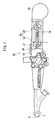
- FIG. 1 is a side view showing an endoscopic treatment system according to a first embodiment of the present invention, in which a part thereof is shown in a cross sectional view.
- FIG. 2 is a side view showing a treatment tool of the endoscopic treatment system.
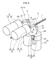
- FIG. 3 is a perspective view of an insertion-retraction and rotating device for a treatment tool, of the endoscopic treatment system.
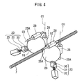
- FIG. 4 is a perspective view of a part of the insertion-retraction and rotating device for a treatment tool, of the endoscopic treatment system.
- FIG. 5 is a perspective view of a part of the endoscopic treatment system.
- FIG. 6 is a perspective view of a part of the endoscopic treatment system.
- FIG. 7 is a side view showing an endoscopic treatment system according to a second embodiment of the present invention, in which a part thereof is shown in a cross sectional view.
- FIG. 8 is a side view of a part of the endoscopic treatment system.
- FIG. 9 is a plan view of the part of the endoscopic treatment system.
- FIG. 10 is a perspective view of a holding member of the endoscopic treatment system.
- FIG. 11 is a side view of a part of the endoscopic treatment system.
- FIG. 12 is a side view showing a part of an endoscopic treatment system according to a third embodiment of the present invention.
- FIG. 13 is a perspective view of a holding member of the endoscopic treatment system.
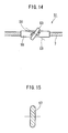
- FIG. 14 is a side view of a part of the endoscopic treatment system.
- FIG. 15 is a cross sectional view of a roller of a variant example of the endoscopic treatment system.
-
- 10
- channel
- 6
- endoscope
- 7
- forceps (a treatment tool)
- 8, 41
- insertion-retraction and rotating device for a treatment tool
- 1, 40, 51
- endoscopic treatment system
- 18, 20
- ball
- 21
- first driving device
- 22
- second driving device
- 45, 46, 53, 57
- roller
- 47
- driving device
- 48, 55
- holding member
- 50, 56
- slit (opening portion)
- t
- length
- r
- radius
- An endoscopic treatment system according to a first embodiment of the present invention will be explained hereinbelow, with reference to FIGS. 1 to 6.
As shown in FIG. 1, anendoscopic treatment system 1 of the present embodiment is provided with: aflexible insertion part 2; anoperation part 3 for operating theinsertion part 2; an endoscope 6 having achannel 5 communicating between the insides of theinsertion part 2 and theoperation part 3; a forceps (a treatment tool) 7 to be inserted into thechannel 5; and an insertion-retraction and rotating device for atreatment tool 8 which performs insertion-retraction of theforceps 7 in thechannel 5, and rotates theforceps 7 centering on the insertion-retraction direction; and anaccommodating portion 10 connected to the operatingportion 3 and accommodates at least a proximal end side of theforceps 7. - As shown in FIG. 2, the
forceps 7 is provided with: aforcep portion 11 which opens and closes when an insertion-retraction driving power is applied onto anoperation wire 13; aflexible sheath portion 12 having a distal end to which theforcep portion 11 is attached; theoperation wire 13 inserted in thesheath portion 12 so as to be insertable and retractable, and transfers the insertion-retraction driving power to theforcep portion 11; and anoperation duct portion 15 arranged so as to be separated securing a predetermined length from the proximal end of thesheath portion 12, and is connected to the proximal end of theoperation wire 13.
As shown in FIG. 1, the insertion-retraction and rotating device for atreatment tool 8 includes: a distal-end-side insertion-retraction and rotating device for atreatment tool 16 arranged in apassage 5A communicating between the insides of thechannel 5 and theaccommodating portion 10 within the operatingportion 3; and a proximal-end-side insertion-retraction and rotating device for atreatment tool 17 arranged on the retraction side than the distal-end-side insertion-retraction and rotating device for a treatment tool 16 (i.e., on the right side of FIG. 1) so as to be separated therefrom. An interval between the distal-end-side insertion-retraction and rotating device for atreatment tool 16 and the proximal-end-side insertion-retraction and rotating device for atreatment tool 17 is longer than the length of a portion of theforcep portion 11 protruded from the distal end of thechannel 5. - As shown in FIGS. 3 to 6, each of the distal-end-side insertion-retraction and rotating device for a
treatment tool 16 and the a proximal-end-side insertion-retraction and rotating device for atreatment tool 17 includes: a pair ofballs forceps 7 therebetween; a pair offirst driving devices 21 which rotate theballs torsion axes C 1 vertical to the planar face including the axis of theforceps 7; a pair ofsecond driving devices 22 which rotate theballs forceps 7; and a pair of pushingportions 23 which push theballs forceps 7. - Each of the
first driving device 21 and thesecond driving device 22 is provided with amotor 25, and agear box 26 accommodating gears for adjusting the rotational number and the torque of themotor 25. Each ofrotational axes 25A joined with a rotational axis of themotor 25 via the gears, is joined with aball roller 28 which extends along the axial direction of therotational axis 25A and makes a press-contacting with respect to theballs
Each of the pushingportions 23 is provided with: a pushingroller 30 which contacts one of theballs ball roller supporting portion 31 which supports theroller 30 such that theroller 30 follows the rotational direction of theball spring portion 32 which urges theroller supporting portion 31 toward theball
Each of the pushingportions 23 is arranged at a position where it can press both of theball roller 28 and theforceps 7. - The
balls operation part 3. Each of inner faces of the ball-accommodatingportion 33 has a curved shape in accordance with the shape of theballs balls
As shown in FIG 1, an insertion-retraction switch 35 for performing an insertion-retraction operation of theforceps 7 within thechannel 5; arotation switch 36 for a rotation operation of theforceps 7 around the axis thereof; and an open-close switch 37 for opening and closing operations of theforcep portion 11, are arranged at theoperation portion 3. - Next, an operation method, and an operation and an advantageous effect of the
endoscopic treatment system 1 according to the present embodiment will be explained in the following.
Firstly, theinsertion part 2 of the endoscope 6 is inserted into a body cavity.
When performing procedures, thefirst driving devices 21 of the distal-end-side insertion-retraction and rotating device for atreatment tool 16 and the proximal-end-side insertion-retraction and rotating device for atreatment tool 17 are driven by operating the insertion-retraction switch 35. Then, each of theball roller 28 contacting theball 18 and theball roller 28 contacting theball 20 is rotated around the torsion axesC 1 thereof in the reversed rotational direction with each other and in the same rotational speed.
At this time, each of theballs ball rollers 28, and thereby theforceps 7 pressed by theballs channel 5 and the rotational direction of theballs
After protruding theforceps 7 for a predetermined length from the distal end of thechannel 5, forwarding of theforceps 7 is stopped by operating the insertion-retraction switch 35. - If the rotational direction of the
forcep portion 11 and the clamping direction for the tissue differ, therotation switch 36 is operated. By this, thesecond driving devices 22 of the distal-end-side insertion-retraction and rotating device for atreatment tool 16 and the proximal-end-side insertion-retraction and rotating device for atreatment tool 17 are each driven. Then, each of theball roller 28 contacting theball 18 and theball roller 28 contacting theball 20 is rotated around the parallel axes C2 thereof in the reversed rotational direction with each other and in the same rotational speed.
As a result, each of theballs ball rollers 28, and thereby theforceps 7 pushed by theballs balls - While performing the procedures, only the
first driving device 21 on the proximal-end-side insertion-retraction and rotating device for atreatment tool 17 side is activated by operating the open-close switch 37. Then, each of theball rollers 28 on the proximal-end-side insertion-retraction and rotating device for atreatment tool 17 side is driven to rotate in the forward direction in which theforceps 7 moves toward the distal end of thechannel 5.
At this time, since both of theoperation duct portion 15 and theoperation wire 13 move in the forward direction with respect to thesheath portion 12, driving power is transmitted to theforcep portion 11, and thereby enabling driving of theforcep portion 11. - After the procedures, the
first driving devices 21 of the distal-end-side insertion-retraction and rotating device for atreatment tool 16 and the proximal-end-side insertion-retraction and rotating device for atreatment tool 17 are driven such that theballs retraction switch 35. As a result, theforceps 7 is retracted. - According to the above-mentioned
endoscopic treatment system 1 of the present embodiment, theforceps 7 can be moved along the rotational direction of theballs first driving device 21 while theballs forceps 7. Furthermore, the insertion-retraction direction of theforceps 7 can also be operated by rotating theballs
In addition, theforceps 7 can be moved along the rotational direction of theballs second driving device 22. Furthermore, the rotational direction of theforceps 7 around the axis thereof can also be operated by rotating theballs - Next, an
endoscopic treatment system 40 according to a second embodiment of the present invention will be explained in the following with reference to FIGS. 7 to 11. Moreover, the same symbols will be applied onto the same constituent elements as those of the above-mentioned first embodiment, and the explanation therefor will be omitted.
Theendoscopic treatment system 40 of the present embodiment differs with theendoscopic treatment system 1 of the first embodiment in the point in that a distal end side insertion-retraction and rotating device for atreatment tool 42 and a proximal end side insertion-retraction and rotating device for atreatment tool 43 of an insertion-retraction and rotating device for atreatment tool 41 is provided with, as shown in FIGS. 7 to 9, tworollers forceps 7 therebetween, and twodriving devices 47 which rotationally drive theserollers - Each of the driving
devices 47 includes amotor 25, and agear box 26 accommodating gears for adjusting the rotational number and the torque of themotor 25. Each of the tworollers rotational axis 25A which is joined with a rotational axis of themotor 25 via the gears.
Each of therollers member 48 which holds a contacting portion between therollers forceps 7 is arranged at a position where therollers forceps 7 contact with each other. This holdingmember 48 holds theforceps 7 which passes through thereinside such that theforceps 7 is insertable and retractable along the axial direction of theforceps 7 and such that theforceps 7 is rotatable around the axis of theforceps 7. As shown in FIG. 11, a pair ofslits 50 are formed on an exterior of the holdingmember 48 so as to extend along the axial direction of the holdingmember 48. Therollers forceps 7 inside the holdingmember 48 through theslits 50. - Next, an operation method, and an operation and an advantageous effect of the
endoscopic treatment system 40 will be explained in the following.
Firstly, theinsertion part 2 is inserted into a body cavity. When performing procedures, therollers roller 45 is rotated in the clockwise while theroller 46 is rotated in the anticlockwise), by operating the insertion-retraction switch 35. At this time, as shown in FIG. 8, a force F1 which is orthogonal to the torsion axis C3 and has the same direction as that of the torsion axis C3 is applied onto theforceps 7. Since theforceps 7 is supported by the holdingmember 48, only a component taking along the axial direction of theforceps 7, of the force F1 works on theforceps 7; thereby, theforceps 7 moves along the axial direction thereof. - If the rotational direction of the
forcep portion 11 and the clamping direction of the tissue differ, therollers rotation switch 36. Then, forces F2 which are orthogonal to the torsion axis C3 and have the opposite direction with each other are applied onto theforceps 7. Since theforceps 7 is supported by the holdingmember 48, components taking along the axial direction of theforceps 7, of the forces F2 are cancelled with each other; therefore, only components which provide a rotational torque onto theforceps 7 works onto theforceps 7 and rotates theforceps 7 around the axis thereof.
In the case in which theforceps 7 needs to be rotated in the opposite direction as of the above-mentioned rotational direction, therollers forceps 7 rotates around the axis thereof (However, the rotational direction thereof is opposite with respect to the above-mentioned rotational direction). - According to the above-mentioned
endoscopic treatment system 40 of the present embodiment, by driving rotations of therollers device 47 while sandwiching theforceps 7 between therollers forceps 7 and a component orthogonal to the insertion-retraction direction of theforceps 7, toward the direction orthogonal to the torsion axis C1. In this case, by making therollers forceps 7 can be inserted and retracted within thechannel 5. In addition, by making therollers forceps 7 can be rotated around the axis thereof. - Next, an
endoscopic treatment system 51 according to a third embodiment of the present invention will be explained in the following with reference to FIGS. 12 to 14. Moreover, the same symbols will be applied onto the same constituent elements as those of the above-mentioned other embodiments, and the explanation therefor will be omitted.
Theendoscopic treatment system 51 of the present embodiment differs with theendoscopic treatment system 40 of the second embodiment in the point in thatrollers 53 having flat-shape (disc-shape) in which a radius r centering on the torsion axis C3 is longer than the length t taking along the axial direction of the torsion axis C3. -
Slits 56 provided in a holdingmember 55 are formed in an inclined direction with respect to the rotational axis of theforceps 7 such that therollers 53 and theforceps 7 contact with each other.
Theendoscopic treatment system 51 can also obtain the same operations and advantageous effect as those of theendoscopic treatment system 40 according to the above-mentioned second embodiment. Furthermore, theendoscopic treatment system 51 of the present embodiment can obtain a smaller contacting area between theforceps 7 and therollers 53; thereby, enabling reducing friction forces between therollers 53 and theforceps 7. Accordingly, force from therollers 53 can be efficiently transferred to theforceps 7.
Moreover, in the present embodiment, contacting faces of therollers 53 with respect to theforceps 7 are made planar; however, as shown in for example FIG. 15,rollers 57 each having a round-shaped contacting surface which makes a line contact with the forceps in order to further reduce the contacting area with respect to theforceps 7 may be adopted. In this case, pushing force of therollers 57 toward theforceps 7 can be increased; thereby, enabling efficient transmission of the rotations of therollers 57 to theforceps 7. - While preferred embodiments of the invention have been described and illustrated above, it should be understood that these are exemplary of the invention and are not to be considered as limiting. Additions, omissions, substitutions, and other modifications can be made without departing from the spirit or scope of the present invention. Accordingly, the invention is not to be considered as being limited by the foregoing description, and is only limited by the scope of the appended claims.
- According to an endoscopic treatment system of the present invention, by automatically performing insertion-retraction operation and rotating operation, it becomes possible to perform manual procedure using a treatment tool easily and in shorter time.
Claims (7)
- An endoscopic treatment system comprising an insertion-retraction and rotating device for a treatment tool, which performs an insertion-retraction operation along a direction of an axis of a treatment tool and a rotating operation around the axis, of the treatment tool inserted in a channel of an endoscope.
- The endoscopic treatment system according to claim 1, wherein
the insertion-retraction and rotating device for a treatment tool comprises:at least two balls which are to be in contact with the treatment tool;a first driving device which drives rotations of the balls around an axis orthogonal to an insertion-retraction direction of the treatment tool; anda second driving device which drives rotations of the balls around an axis parallel to the insertion-retraction direction of the treatment tool. - The endoscopic treatment system according to claim 1, wherein
the insertion-retraction and rotating device for a treatment tool comprises:at least two rollers which are to be in contact with the treatment tool; anda driving device which drives rotations of the rollers around an axis inclined with respect to a planar face orthogonal to the insertion-retraction direction of the treatment tool. - The endoscopic treatment system according to claim 3, further comprising a holding member which holds a contacting portion between the treatment tool and the rollers, wherein
an opening which permits contacts between the treatment tool and the rollers is formed in the holding member. - The endoscopic treatment system according to claim 3, wherein
each of the rollers has a disc shape having a length shorter than a radius centering on a rotating axis thereof. - The endoscopic treatment system according to claim 5, further comprising a holding member which holds a contacting portion between the treatment tool and the rollers, wherein
an opening which permits contacts between the treatment tool and the rollers is formed in the holding member. - The endoscopic treatment system according to claim 3, wherein
each of the rollers makes a line contact with respect to the treatment tool.
Applications Claiming Priority (2)
| Application Number | Priority Date | Filing Date | Title |
|---|---|---|---|
| JP2004119984A JP4542362B2 (en) | 2004-04-15 | 2004-04-15 | Endoscopic treatment system |
| PCT/JP2005/006777 WO2005099557A1 (en) | 2004-04-15 | 2005-04-06 | Endoscope treatment system |
Publications (3)
| Publication Number | Publication Date |
|---|---|
| EP1736093A1 true EP1736093A1 (en) | 2006-12-27 |
| EP1736093A4 EP1736093A4 (en) | 2008-01-23 |
| EP1736093B1 EP1736093B1 (en) | 2010-05-05 |
Family
ID=35149720
Family Applications (1)
| Application Number | Title | Priority Date | Filing Date |
|---|---|---|---|
| EP05728474A Expired - Lifetime EP1736093B1 (en) | 2004-04-15 | 2005-04-06 | Endoscope treatment system |
Country Status (5)
| Country | Link |
|---|---|
| US (1) | US7955252B2 (en) |
| EP (1) | EP1736093B1 (en) |
| JP (1) | JP4542362B2 (en) |
| DE (1) | DE602005021084D1 (en) |
| WO (1) | WO2005099557A1 (en) |
Families Citing this family (11)
| Publication number | Priority date | Publication date | Assignee | Title |
|---|---|---|---|---|
| EP1946693B1 (en) * | 2005-10-19 | 2011-04-13 | Olympus Corporation | Endoscope system |
| JP5128979B2 (en) * | 2008-02-15 | 2013-01-23 | オリンパスメディカルシステムズ株式会社 | Rotating self-propelled endoscope |
| WO2010003248A1 (en) * | 2008-07-10 | 2010-01-14 | Mcmaster University | Endoscopic device with end effector mechanism |
| US20120191107A1 (en) | 2010-09-17 | 2012-07-26 | Tanner Neal A | Systems and methods for positioning an elongate member inside a body |
| US20130035537A1 (en) * | 2011-08-05 | 2013-02-07 | Wallace Daniel T | Robotic systems and methods for treating tissue |
| US10569052B2 (en) | 2014-05-15 | 2020-02-25 | Auris Health, Inc. | Anti-buckling mechanisms for catheters |
| EP3209189A1 (en) * | 2014-10-23 | 2017-08-30 | Koninklijke Philips N.V. | Handheld catheter driver with endoscope mount utilizing friction-driven wheel mechanism |
| JP6534844B2 (en) * | 2015-03-31 | 2019-06-26 | 学校法人慶應義塾 | Medical treatment tool holder |
| JP6565104B2 (en) * | 2015-05-21 | 2019-08-28 | シャープ株式会社 | Actuator |
| US10806489B2 (en) * | 2015-07-31 | 2020-10-20 | Purdue Research Foundation | Systems and methods for performing a surgical procedure |
| KR102682015B1 (en) * | 2021-11-29 | 2024-07-05 | 재단법인대구경북과학기술원 | Apparatus For Controlling Endoscope |
Family Cites Families (26)
| Publication number | Priority date | Publication date | Assignee | Title |
|---|---|---|---|---|
| US2036887A (en) * | 1932-07-13 | 1936-04-07 | Johns Manville | Pipe wrapping machine |
| US3625276A (en) * | 1969-02-10 | 1971-12-07 | Apv Co Ltd | Centrifugal casting of tubes including slag separation |
| CA935059A (en) * | 1970-02-27 | 1973-10-09 | Jewett-Ashley Holding Corp. | Catheter device |
| US3800580A (en) * | 1973-01-08 | 1974-04-02 | Armco Steel Corp | Thread rolling apparatus |
| JPS57117823A (en) * | 1981-01-14 | 1982-07-22 | Olympus Optical Co | Endoscope with apparatus for inserting and pulling out treating tool |
| US4530507A (en) * | 1983-08-01 | 1985-07-23 | Lee Jr Roy | Vibration dampening and workpiece guiding rollers for a chuck |
| US5060632A (en) * | 1989-09-05 | 1991-10-29 | Olympus Optical Co., Ltd. | Endoscope apparatus |
| US5976129A (en) * | 1991-10-18 | 1999-11-02 | Desai; Ashvin H. | Endoscopic surgical instrument |
| US5346498A (en) * | 1991-11-06 | 1994-09-13 | Imagyn Medical, Inc. | Controller for manipulation of instruments within a catheter |
| US5309746A (en) * | 1993-01-28 | 1994-05-10 | Abbey Etna Machine Company | Automatic tube straightening system |
| US5318541A (en) * | 1993-03-02 | 1994-06-07 | Cordis Corporation | Apparatus for catheter exchange in vascular dilitation |
| JP3466010B2 (en) * | 1995-11-28 | 2003-11-10 | オリンパス光学工業株式会社 | Endoscope treatment instrument insertion / removal device |
| EP1011778A1 (en) * | 1997-01-09 | 2000-06-28 | EndoSonics Corporation | Device for withdrawing a catheter |
| JPH11104071A (en) * | 1997-08-05 | 1999-04-20 | Olympus Optical Co Ltd | Treating instrument for endoscope |
| IL123646A (en) * | 1998-03-11 | 2010-05-31 | Refael Beyar | Remote control catheterization |
| DE29808180U1 (en) * | 1998-05-06 | 1998-07-23 | STM Medizintechnik Starnberg GmbH, 86947 Weil | Drive device for slip hose system |
| JP4187320B2 (en) * | 1998-10-05 | 2008-11-26 | オリンパス株式会社 | Endoscope insertion device |
| US6817973B2 (en) * | 2000-03-16 | 2004-11-16 | Immersion Medical, Inc. | Apparatus for controlling force for manipulation of medical instruments |
| WO2001089598A2 (en) * | 2000-05-19 | 2001-11-29 | C.R. Bard, Inc. | Guidewire with viewing capability |
| JP4551051B2 (en) * | 2002-04-17 | 2010-09-22 | オリンパス株式会社 | Ultrasonic diagnostic equipment |
| IL165224A0 (en) * | 2002-05-31 | 2005-12-18 | Vidacare Corp | Apparatus and method to access bone marrow |
| JP4037693B2 (en) * | 2002-06-17 | 2008-01-23 | オリンパス株式会社 | Medical device and treatment tool |
| US6849989B2 (en) * | 2002-10-31 | 2005-02-01 | Andreas Schmid | Translation and rotation positioning motor |
| US6872178B2 (en) * | 2002-11-18 | 2005-03-29 | Andrew Mark Weinberg | Colonoscope apparatus and method |
| EP1442720A1 (en) * | 2003-01-31 | 2004-08-04 | Tre Esse Progettazione Biomedica S.r.l | Apparatus for the maneuvering of flexible catheters in the human cardiovascular system |
| JP3818997B2 (en) * | 2003-10-06 | 2006-09-06 | オリンパス株式会社 | Endoscope |
-
2004
- 2004-04-15 JP JP2004119984A patent/JP4542362B2/en not_active Expired - Fee Related
-
2005
- 2005-04-06 WO PCT/JP2005/006777 patent/WO2005099557A1/en not_active Ceased
- 2005-04-06 DE DE602005021084T patent/DE602005021084D1/en not_active Expired - Lifetime
- 2005-04-06 EP EP05728474A patent/EP1736093B1/en not_active Expired - Lifetime
-
2006
- 2006-06-05 US US11/446,999 patent/US7955252B2/en not_active Expired - Fee Related
Also Published As
| Publication number | Publication date |
|---|---|
| DE602005021084D1 (en) | 2010-06-17 |
| WO2005099557A1 (en) | 2005-10-27 |
| EP1736093B1 (en) | 2010-05-05 |
| JP2005296485A (en) | 2005-10-27 |
| US7955252B2 (en) | 2011-06-07 |
| EP1736093A4 (en) | 2008-01-23 |
| US20060224162A1 (en) | 2006-10-05 |
| JP4542362B2 (en) | 2010-09-15 |
Similar Documents
| Publication | Publication Date | Title |
|---|---|---|
| JP4727158B2 (en) | Endoscope system | |
| US7789822B2 (en) | Endoscopic therapeutic instrument, endoscope, and endoscopic therapeutic system | |
| US8221305B2 (en) | Endoscope treatment tool system | |
| CN103687553B (en) | Armarium | |
| JP4593129B2 (en) | Endoscope | |
| EP2777552B1 (en) | Wire driver | |
| CN101238971B (en) | Treatment tool for endoscope | |
| EP1736093A1 (en) | Endoscope treatment system | |
| JP2005237659A (en) | Endoscopic treatment system | |
| US6033424A (en) | Treating instrument for endoscope | |
| US10010376B2 (en) | Medical manipulator | |
| WO2020079824A1 (en) | Endoscope treatment tool | |
| JP2005328968A (en) | Endoscope processing system | |
| US20200038047A1 (en) | Medical treatment tool | |
| JP4451206B2 (en) | Endoscope system | |
| JP2005349090A (en) | Treatment tool for endoscope | |
| JP2005218624A (en) | Endoscope treatment system and treating implement for endoscope | |
| JPWO2010071064A1 (en) | Treatment tool | |
| JP4349703B2 (en) | Endoscopic treatment tool | |
| JP4546159B2 (en) | Endoscope and endoscope treatment system | |
| CN120616696A (en) | Traction device for digestive endoscopy operation | |
| JP2005270293A (en) | Treatment tool for endoscope and treatment system of endoscope | |
| JP2006026071A (en) | Endoscope treatment system | |
| JP2005230333A (en) | Instrument for endoscope |
Legal Events
| Date | Code | Title | Description |
|---|---|---|---|
| PUAI | Public reference made under article 153(3) epc to a published international application that has entered the european phase |
Free format text: ORIGINAL CODE: 0009012 |
|
| 17P | Request for examination filed |
Effective date: 20060811 |
|
| AK | Designated contracting states |
Kind code of ref document: A1 Designated state(s): DE FR GB IE |
|
| DAX | Request for extension of the european patent (deleted) | ||
| RBV | Designated contracting states (corrected) |
Designated state(s): DE FR GB IE |
|
| A4 | Supplementary search report drawn up and despatched |
Effective date: 20080102 |
|
| RIC1 | Information provided on ipc code assigned before grant |
Ipc: A61B 1/018 20060101ALI20071220BHEP Ipc: A61B 17/00 20060101ALI20071220BHEP Ipc: A61B 1/00 20060101AFI20051101BHEP |
|
| 17Q | First examination report despatched |
Effective date: 20090119 |
|
| GRAP | Despatch of communication of intention to grant a patent |
Free format text: ORIGINAL CODE: EPIDOSNIGR1 |
|
| GRAS | Grant fee paid |
Free format text: ORIGINAL CODE: EPIDOSNIGR3 |
|
| GRAA | (expected) grant |
Free format text: ORIGINAL CODE: 0009210 |
|
| AK | Designated contracting states |
Kind code of ref document: B1 Designated state(s): DE FR GB IE |
|
| REG | Reference to a national code |
Ref country code: GB Ref legal event code: FG4D |
|
| REG | Reference to a national code |
Ref country code: IE Ref legal event code: FG4D |
|
| REF | Corresponds to: |
Ref document number: 602005021084 Country of ref document: DE Date of ref document: 20100617 Kind code of ref document: P |
|
| PLBE | No opposition filed within time limit |
Free format text: ORIGINAL CODE: 0009261 |
|
| STAA | Information on the status of an ep patent application or granted ep patent |
Free format text: STATUS: NO OPPOSITION FILED WITHIN TIME LIMIT |
|
| 26N | No opposition filed |
Effective date: 20110208 |
|
| REG | Reference to a national code |
Ref country code: DE Ref legal event code: R097 Ref document number: 602005021084 Country of ref document: DE Effective date: 20110207 |
|
| PGFP | Annual fee paid to national office [announced via postgrant information from national office to epo] |
Ref country code: IE Payment date: 20130417 Year of fee payment: 9 |
|
| PGFP | Annual fee paid to national office [announced via postgrant information from national office to epo] |
Ref country code: GB Payment date: 20140402 Year of fee payment: 10 |
|
| PGFP | Annual fee paid to national office [announced via postgrant information from national office to epo] |
Ref country code: FR Payment date: 20140409 Year of fee payment: 10 |
|
| REG | Reference to a national code |
Ref country code: IE Ref legal event code: MM4A |
|
| PG25 | Lapsed in a contracting state [announced via postgrant information from national office to epo] |
Ref country code: IE Free format text: LAPSE BECAUSE OF NON-PAYMENT OF DUE FEES Effective date: 20140406 |
|
| GBPC | Gb: european patent ceased through non-payment of renewal fee |
Effective date: 20150406 |
|
| PG25 | Lapsed in a contracting state [announced via postgrant information from national office to epo] |
Ref country code: GB Free format text: LAPSE BECAUSE OF NON-PAYMENT OF DUE FEES Effective date: 20150406 |
|
| REG | Reference to a national code |
Ref country code: FR Ref legal event code: ST Effective date: 20151231 |
|
| PG25 | Lapsed in a contracting state [announced via postgrant information from national office to epo] |
Ref country code: FR Free format text: LAPSE BECAUSE OF NON-PAYMENT OF DUE FEES Effective date: 20150430 |
|
| PGFP | Annual fee paid to national office [announced via postgrant information from national office to epo] |
Ref country code: DE Payment date: 20190418 Year of fee payment: 15 |
|
| REG | Reference to a national code |
Ref country code: DE Ref legal event code: R119 Ref document number: 602005021084 Country of ref document: DE |
|
| PG25 | Lapsed in a contracting state [announced via postgrant information from national office to epo] |
Ref country code: DE Free format text: LAPSE BECAUSE OF NON-PAYMENT OF DUE FEES Effective date: 20201103 |