EP1735877B1 - Coaxial cable connector and nut member - Google Patents
Coaxial cable connector and nut member Download PDFInfo
- Publication number
- EP1735877B1 EP1735877B1 EP05730267A EP05730267A EP1735877B1 EP 1735877 B1 EP1735877 B1 EP 1735877B1 EP 05730267 A EP05730267 A EP 05730267A EP 05730267 A EP05730267 A EP 05730267A EP 1735877 B1 EP1735877 B1 EP 1735877B1
- Authority
- EP
- European Patent Office
- Prior art keywords
- nut member
- flat sides
- grooved
- driving head
- annular portion
- Prior art date
- Legal status (The legal status is an assumption and is not a legal conclusion. Google has not performed a legal analysis and makes no representation as to the accuracy of the status listed.)
- Expired - Lifetime
Links
- 239000004020 conductor Substances 0.000 description 6
- 238000003780 insertion Methods 0.000 description 5
- 230000007613 environmental effect Effects 0.000 description 3
- 230000037431 insertion Effects 0.000 description 3
- 230000000295 complement effect Effects 0.000 description 2
- 230000006835 compression Effects 0.000 description 2
- 238000007906 compression Methods 0.000 description 2
- 230000008878 coupling Effects 0.000 description 2
- 238000010168 coupling process Methods 0.000 description 2
- 238000005859 coupling reaction Methods 0.000 description 2
- 239000011888 foil Substances 0.000 description 2
- 238000004519 manufacturing process Methods 0.000 description 2
- 239000002184 metal Substances 0.000 description 2
- 238000007789 sealing Methods 0.000 description 2
- 238000001125 extrusion Methods 0.000 description 1
- 210000003811 finger Anatomy 0.000 description 1
- 238000003754 machining Methods 0.000 description 1
- 238000000034 method Methods 0.000 description 1
- 238000012986 modification Methods 0.000 description 1
- 230000004048 modification Effects 0.000 description 1
- 230000001681 protective effect Effects 0.000 description 1
- 210000003813 thumb Anatomy 0.000 description 1
Images



Classifications
-
- H—ELECTRICITY
- H01—ELECTRIC ELEMENTS
- H01R—ELECTRICALLY-CONDUCTIVE CONNECTIONS; STRUCTURAL ASSOCIATIONS OF A PLURALITY OF MUTUALLY-INSULATED ELECTRICAL CONNECTING ELEMENTS; COUPLING DEVICES; CURRENT COLLECTORS
- H01R9/00—Structural associations of a plurality of mutually-insulated electrical connecting elements, e.g. terminal strips or terminal blocks; Terminals or binding posts mounted upon a base or in a case; Bases therefor
- H01R9/03—Connectors arranged to contact a plurality of the conductors of a multiconductor cable, e.g. tapping connections
- H01R9/05—Connectors arranged to contact a plurality of the conductors of a multiconductor cable, e.g. tapping connections for coaxial cables
-
- H—ELECTRICITY
- H01—ELECTRIC ELEMENTS
- H01R—ELECTRICALLY-CONDUCTIVE CONNECTIONS; STRUCTURAL ASSOCIATIONS OF A PLURALITY OF MUTUALLY-INSULATED ELECTRICAL CONNECTING ELEMENTS; COUPLING DEVICES; CURRENT COLLECTORS
- H01R24/00—Two-part coupling devices, or either of their cooperating parts, characterised by their overall structure
- H01R24/38—Two-part coupling devices, or either of their cooperating parts, characterised by their overall structure having concentrically or coaxially arranged contacts
- H01R24/40—Two-part coupling devices, or either of their cooperating parts, characterised by their overall structure having concentrically or coaxially arranged contacts specially adapted for high frequency
-
- H—ELECTRICITY
- H01—ELECTRIC ELEMENTS
- H01R—ELECTRICALLY-CONDUCTIVE CONNECTIONS; STRUCTURAL ASSOCIATIONS OF A PLURALITY OF MUTUALLY-INSULATED ELECTRICAL CONNECTING ELEMENTS; COUPLING DEVICES; CURRENT COLLECTORS
- H01R13/00—Details of coupling devices of the kinds covered by groups H01R12/70 or H01R24/00 - H01R33/00
- H01R13/62—Means for facilitating engagement or disengagement of coupling parts or for holding them in engagement
-
- H—ELECTRICITY
- H01—ELECTRIC ELEMENTS
- H01R—ELECTRICALLY-CONDUCTIVE CONNECTIONS; STRUCTURAL ASSOCIATIONS OF A PLURALITY OF MUTUALLY-INSULATED ELECTRICAL CONNECTING ELEMENTS; COUPLING DEVICES; CURRENT COLLECTORS
- H01R43/00—Apparatus or processes specially adapted for manufacturing, assembling, maintaining, or repairing of line connectors or current collectors or for joining electric conductors
- H01R43/20—Apparatus or processes specially adapted for manufacturing, assembling, maintaining, or repairing of line connectors or current collectors or for joining electric conductors for assembling or disassembling contact members with insulating base, case or sleeve
- H01R43/22—Hand tools
-
- H—ELECTRICITY
- H01—ELECTRIC ELEMENTS
- H01R—ELECTRICALLY-CONDUCTIVE CONNECTIONS; STRUCTURAL ASSOCIATIONS OF A PLURALITY OF MUTUALLY-INSULATED ELECTRICAL CONNECTING ELEMENTS; COUPLING DEVICES; CURRENT COLLECTORS
- H01R9/00—Structural associations of a plurality of mutually-insulated electrical connecting elements, e.g. terminal strips or terminal blocks; Terminals or binding posts mounted upon a base or in a case; Bases therefor
- H01R9/03—Connectors arranged to contact a plurality of the conductors of a multiconductor cable, e.g. tapping connections
- H01R9/05—Connectors arranged to contact a plurality of the conductors of a multiconductor cable, e.g. tapping connections for coaxial cables
- H01R9/0521—Connection to outer conductor by action of a nut
-
- H—ELECTRICITY
- H01—ELECTRIC ELEMENTS
- H01R—ELECTRICALLY-CONDUCTIVE CONNECTIONS; STRUCTURAL ASSOCIATIONS OF A PLURALITY OF MUTUALLY-INSULATED ELECTRICAL CONNECTING ELEMENTS; COUPLING DEVICES; CURRENT COLLECTORS
- H01R13/00—Details of coupling devices of the kinds covered by groups H01R12/70 or H01R24/00 - H01R33/00
- H01R13/62—Means for facilitating engagement or disengagement of coupling parts or for holding them in engagement
- H01R13/622—Screw-ring or screw-casing
-
- H—ELECTRICITY
- H01—ELECTRIC ELEMENTS
- H01R—ELECTRICALLY-CONDUCTIVE CONNECTIONS; STRUCTURAL ASSOCIATIONS OF A PLURALITY OF MUTUALLY-INSULATED ELECTRICAL CONNECTING ELEMENTS; COUPLING DEVICES; CURRENT COLLECTORS
- H01R2103/00—Two poles
Definitions
- a connector for coupling an end of a coaxial cable to a threaded terminal comprising: a cylindrical body member having a rear end adapted to receive the end of the coaxial cable, a front end, and a central hole extending through the cylindrical body from the rear end to the front end; a nut member having a central hole extending through the nut member, wherein the nut member engages the front end of the cylindrical body member; and a post member comprising a post flange and a post shank, the post member disposed at least partially within the central hole of the cylindrical body member at the front end of the cylindrical body member and disposed at least partially within the central hole of the nut member, wherein the post member and the cylindrical body member are movable with respect to each other in a cable-insertion position, wherein the post member and the cylindrical body member are adapted to sandwich a part of the coaxial cable in a cable-installed position; wherein the nut member comprises a nut body having a central longitudinal axis,
- the inner side surface of the driving head portion has threads. In another preferred embodiment, the inner side surface of the annular portion has threads. In yet another preferred embodiment, the inner side surfaces of the driving head portion and the inner side surface of the annular portion have threads.
- none of the grooves has a maximum depth greater than the minimum radial offset between the outer side surfaces of the driving head portion and the annular portion.
- the grooved flat sides have a longitudinal groove disposed between adjacent corner edges and closer to the corner edge upon which torque is applied when tightening the nut.
- each grooved flat side has a transverse width W F and a total groove width, and the ratio ⁇ w i / W F is greater than 0.05, more preferably greater than 0.10, even more preferably greater than 0.15, for each of the grooved flat sides.
- each grooved flat side has a transverse width W F and a total groove width, and the ratio ⁇ w i / W F is between 0.10 and 0.9 for each of the grooved flat sides.
- none of the grooves has a maximum depth greater than the difference between the minimum radial distance R F from the central longitudinal axis and the maximum radius of the outer side surface of the annular portion.
- the flats have a transverse width W F , and all of the grooves are spaced away from the corner edges by at least 0.10 W F . More preferably, the flats have a transverse width W F , and all of the grooves are spaced away from the corner edges by at least 0.12 W F . Even more preferably, the flats have a transverse width W F , and all of the grooves are spaced away from the corner edges by at least 0.14 W F .
- a majority of the flat sides are grooved with at least one longitudinal groove.
- all of the flat sides are grooved with at least one longitudinal groove.
- all of the flat sides are grooved with at least two longitudinal grooves.
- none of the longitudinal grooves extend onto the outer side surface of the annular portion.
- the outer side surface of the annular portion has no longitudinal grooves.
- the central hole extends through the nut member from end to end, and preferably the central hole is centered about the central longitudinal axis.
- a connector comprising a nut member having a driving head portion as described herein and a wrench adapted to engage the driving head portion of the nut member of the connector.
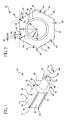
- FIG. 1 is an isometric view of one preferred embodiment of a nut member as disclosed herein.
- FIG. 2 is an end view of the nut member of FIG. 1 .
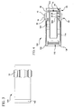
- FIG. 3 is a side view of one preferred embodiment of a connector as disclosed herein.
- FIG. 4 is a side cutaway view along the centerline of the connector of FIG. 3 in a cable insertion state.
- FIG. 5 is a side cutaway view along the centerline of the connector of FIG. 3 in a cable-installed state.
- FIG. 6 is an end view of the connector of FIGS. 3-5 .
- FIG. 8 is an isometric view of the nut member of the connector of FIGS. 3-6 .
- FIG. 10 is an end view of yet another preferred embodiment of a connector having yet another preferred embodiment of a nut member, as disclosed herein.
- FIG. 11 shows a side view of still another embodiment of a coaxial cable connector as disclosed herein.
- FIG. 14 is an end view of the tool 300 of FIGS. 12-13 .
- the nut member 10 comprises a nut body 12 having a central longitudinal axis A-A and a central hole 14.
- the nut body 12 comprises a driving head portion 16 and an annular portion 18.
- the driving head portion 16 has a rear end 20, a front end 22, an outer side surface 24, and an inner side surface 26 extending from the rear end 20 to the front end 22.
- the inner side surface 26 defines at least part of the central hole 14.
- the outer side surface 24 comprises a plurality of oppositely disposed flat sides 26 disposed substantially parallel, preferably parallel, with the central longitudinal axis. Each of the flat sides 26 lies in a respective plane, illustrated in FIG.
- Each grooved flat side 26 has a respective total groove width ⁇ w i , wherein the respective maximum depth of each of the grooves is not greater than the radial offset between the outer side surfaces 24, 36 of the driving head portion 16 and the annular portion 18, that is, for any angular position in a transverse plane that intersects a respective groove 42.
- the radial offset would have a minimum value 42 (i.e. R F - R AO ) compared to a groove situated closer to one of the corner edges 30.
- the depth of a groove 42 is its radial depth.
- none of the grooves 42 extends to the inner side surface 26 of the driving head portion 16 in order to promote environmental sealing between the inner side surface 26 and other surfaces provided by other parts of the connector to which the nut member 10 would become engaged.
- the inner side surface 26 of the driving head portion 16 has threads. In another preferred embodiment, the inner side surface 26 of the annular portion 18 has threads. In yet another preferred embodiment, the inner side surfaces 26 of the driving head portion 16 and the inner side surface 38 of the annular portion 18 have threads.
- the central hole 14 may have a substantially constant diameter or a variable diameter.
- the inner side surface 26 of the driving head portion 16 comprises a flange 44.
- Each grooved flat side 26 has a transverse width W F and a total groove width ⁇ w i .
- the ratio ⁇ w i / W F is greater than 0.05, more preferably greater than 0.10, even more preferably greater than 0.15, for each of the grooved flat sides in order to allow finger or thumb or hand flesh to engage the depressions provided by the grooves 42. That is, a sufficient grooved surface area is required to provide adequate grip by the installer, in the event that a wrench is not utilized for tightening.
- ⁇ w i / W F is less than 1, preferably less than 0.9, more preferably less than 0.8. In preferred embodiments, ⁇ w i / W F is between 0.05 and 1.0 for each of the grooved flat sides 26. In other preferred embodiments, each grooved flat side 26 has a transverse width W F and a total groove width, and the ratio ⁇ w i / W F is between 0.10 and 0.9 for each of the grooved flat sides. In other preferred embodiments, each grooved flat side 26 has a transverse width W F and a total groove width, and the ratio ⁇ w i / W F is between 0.15 and 0.8 for each of the grooved flat sides.
- None of the grooves 42 has a maximum depth greater than the difference between the minimum radial distance R F from the central longitudinal axis and the maximum radius of the outer side surface 36 of the annular portion 18.
- each of the grooves 42 are spaced away from the corner edges 30 by a linear distance 48 measured along the respective flat side 26 of at least 0.10 W F , more preferably by at least 0.12 W F , even more preferably by at least 0.14 W F .
- the grooves 42 extend from the rear end 20 to the front end 22 of the driving head portion 16, and the grooves 42 extend continuously from the rear end 20 to the front end 22 of the driving head portion 16.
- one or more grooves may be provided on a flat side 26, wherein the grooves longitudinally extend only partially between the rear end and the front end of the driving head portion 16.
- a plurality of longitudinally aligned spaced apart grooves are disposed on a flat side 26. Multiple grooves of uniform or nonuniform length may be staggered over one or flat sides 26.
- the central hole 14 extends through the nut member 10 from end 20 to end 24, and the central hole 14 is centered about the central longitudinal axis A-A.
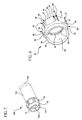
- FIG. 6 is an end view of the connector 100 of FIGS. 3-5 .
- FIG. 7 is an isometric view of the connector of FIGS. 3-6 .
- FIG. 8 is an isometric view of the nut member of the connector of FIGS. 3-6 .
- the connector 100 can be used for coupling an end of a coaxial cable to a threaded terminal.
- the connector 100 comprises a nut member 10, a cylindrical body member 102, and a post member 104.
- the cylindrical body member 102 has a rear end 106 (adapted to receive the end of the coaxial cable), a front end 108, and a central hole 110 extending through the cylindrical body from the rear end 106 to the front end 108.
- the nut member 10 has a central hole 110 extending through the nut member.
- the nut member 10 engages the front end 108 of the cylindrical body member 102.
- the post member 104 comprises a post flange 112 and a post shank 114. In both a cable insertion position (prior to securement of the connector 100 to the coaxial cable as illustrated in FIG. 4 ) and a cable-installed position (as illustrated in FIG. 5 ), the post member 104 is disposed at least partially within the central hole 110 of the cylindrical body member 102 at the front end 108 of the cylindrical body member 102 and disposed at least partially within the central hole 14 of the nut member 10.
- the post member 104 and the cylindrical body member 102 are movable with respect to each other in the cable-insertion position, wherein the post member 104 and the cylindrical body member 102 are adapted to sandwich a part of the coaxial cable in the cable-installed position.
- the nut member 10 comprises a nut body 12 having a central longitudinal axis A-A, the nut body 12 comprising: a driving head portion 16 having a rear end 20, a front end 22, an outer side surface 24, and an inner side surface 26 extending from the rear end 20 to the front end 22, the inner side surface 26 defining at least part of the central hole 14 of the nut member 10, the inner side surface 26 comprising an annular collar 44 for rotatably engaging the front end 108 of the cylindrical body member 102, the outer side surface 24 comprising a plurality of oppositely disposed flat sides 26 disposed substantially parallel, preferably parallel, with the central longitudinal axis A-A (the axis preferably being shared by the cylindrical body member 102, the post member 104, and the nut member 10), wherein each of the flat sides lies in a respective plane disposed at least a minimum radial distance R F from the central longitudinal axis, wherein the planes of respective adjacent flat sides 26 intersect along respective apex lines 28, preferably parallel with the central longitudinal
- both the inner side surface 26 of the driving head portion 16 and the inner side surface 38 of the annular portion 18 have threads 40 adapted to threadably engage the threaded terminal.
- Each of the flat sides 26 are grooved with two longitudinal grooves 42 intermediate adjacent corner edges 30, each of the grooves 42 having a respective maximum width, w i , and a respective maximum depth, wherein each grooved flat side 26 has a respective total groove width ⁇ w i , wherein the respective maximum depth of each of the grooves 42 is not greater than the radial offset between the outer side surfaces 24, 36 of the driving head portion 16 and the annular portion 18.
- FIG. 6 has a generally rectangular shape.
- FIG. 9 is an end view of a connector 100' as disclosed herein comprising a nut member 10' with rounded grooves 42'.
- FIG. 10 is an end view of a connector 100" as disclosed herein comprising a nut member 10" with V-shaped grooves 42".
- the nut member disclosed herein may be adapted to various types of coaxial connectors, such as F-type, SMA, ENC, SC and other connectors.
- FIG. 11 shows a side view of another embodiment of a coaxial cable connector 200 as disclosed herein.
- the connector 200 comprises a cylindrical body 202, a post member 204, a nut member 210 as disclosed herein, and a compression ring 205.
- Axial movement of the cylindrical body 202 and the compression ring 205 toward each other causes the cylindrical sleeve 207 to compress radially inwardly to sandwich the jacket of a coaxial cable between the post member 204 and the cylindrical sleeve 207.
- FIG. 12 shows a top view of a representative wrench tool-300 such as the Gilbert Security Tool G-SST-US, manufactured and distributed by Coming Gilbert Inc., which is a wrench tool 300 suitable for use with coaxial cable connectors having nut members.
- FIG. 13 is a side view of the tool 300 of FIG. 12.
- FIG. 14 is an end view of the tool 300 of FIGS. 12-13 .
- Tool 300 comprises a generally C-shaped body 302 provided with an axial slot 303 and an inner fastener embracing surface 304 disposed at one end, wherein the inner surface 304 has a contour which mates with a nut member.
- the slot 303 is adapted to permit the tool 300 to be slid over a coaxial cable 310 such that the tool 300 and the cable 310 can be oriented with parallel longitudinal axes.
- the tool 300 can be used to tighten to a terminal 320, or loosen from a terminal, a nut member which forms part of a connector attached to the end of the cable 310.
- the tool 300 comprises contoured inner fastener embracing surfaces 304 at both opposing ends, as illustrated in FIG. 12 .
- the tool 300 also comprises a handle 305 which is preferably pivotally attached to the C-shaped body 304.
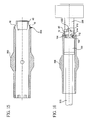
- FIG. 15 is a cutaway cross-sectional side view of the tool 300 of FIG. 12 (handle not shown) in engagement with a nut member 10, as disclosed herein.
- the wrench tool 300 is shown engaging the driving head portion 16 of a nut member 10 of a connector disclosed herein.
- the wrench 300 is open-ended and has a fastener embracing surface 304 generally complementary to at least a portion of the outer side surface of the driving head portion 16 of the nut member 10.
- FIG. 16 is a cutaway cross-sectional side view of the tool 300 of FIG. 12 (handle not shown) in engagement with a connector 100, wherein the connector 100 comprises a nut member 10 shown engaging a terminal 320 and the connector 100 is attached to the end of a coaxial cable 310, as disclosed herein.
- the connector 100 and the terminal 320 are shown in partial cutaway cross-section. A portion of the connector 100 and a portion of the cable 310 are shown disposed within the tool 300.
- the nut member 10 may thus be tightened onto the terminal 320, thereby attaching the connector 100 to the terminal 320, thereby establishing a physical and electrical contact between the cable 310 and the terminal 320.
- the tool 300 may also be used to loosen the nut member 10 from the terminal 320, thereby disengaging the connector 100 from the terminal 320, thereby disconnecting the cable 310 from the terminal 320.
- the connector 100 is attached to the cable 310 in a cable-installed state wherein the outer conductor 316 and the jacket 318 are sandwiched between the cylindrical body member 102 and the shank 114 of the post member 104, wherein the shank 114 has been driven between the dielectric 314 and the outer conductor 316.
- the nut member 10 has been threaded onto the terminal 320, which was surrounded by a seal ring or boot 330, and tightened.
- the interface 332 between abutting surfaces of the seal ring 330 and the annular portion 18 of the nut member 10 forms an environmental seal.
- a seal is established around an entire circumference of the annular portion 18, for example to prevent moisture from entering the connector 100 and/or terminal 320.
- the terminal 320 shown in FIG. 17 comprises prongs 322 which grip the center conductor 312 of cable 310 to establish a physical and electrical connection.
- the driving head portion 16 of the nut member 10 disclosed herein preferably has a polygonal periphery, for example the hexagonal periphery shown in FIGS. 6-10 .
- Other embodiments include square, quadrilateral, octagonal, and other shaped peripheries.
- the periphery is in the shape of a regular polygon, more preferably a regular hexagon.
- the nut member 10 may be made by any known process. Preferably the grooves on the nut member are formed by a die during extrusion. Preferably no machining of the nut member 10 is performed. In some preferred embodiments, the nut member 10 is made from metal. In other preferred embodiments, the nut member 10 is made from plastic.
Landscapes
- Engineering & Computer Science (AREA)
- Manufacturing & Machinery (AREA)
- Coupling Device And Connection With Printed Circuit (AREA)
- Transmission Devices (AREA)
- Communication Cables (AREA)
- Details Of Connecting Devices For Male And Female Coupling (AREA)
Abstract
Description
- The present invention relates generally to coaxial cable connectors, and particularly to coaxial cable connectors capable of being connected to a terminal.
- Coaxial cable connectors such as F-connectors are used to attach coaxial cable to another object such as an appliance or junction having a terminal adapted to engage the connector. A suitably tight connection between a connector and a terminal is typically achieved by using a tool such as a wrench for applying enough torque to the connector. A suitable connection tends to reduce signal leakage and improve signal or picture quality. Typically, use of a tool is acceptable, even encouraged or mandated, in some scenarios, such as when establishing a connection with a terminal located outdoors, on a utility pole and the like. However, tightening, or over-tightening, of connectors to an indoor appliance, such as a television or other electronic equipment, by a tool has in some cases led to the appliance being damaged. Tightening of the connectors in indoor applications is preferably done by hand, i.e. by finger- or hand-tightening. Thus, the installer may need to tighten the same type of connector via tool or via hand, depending on the scenario. However, an adequate grip on the connector to establish satisfactorily tight connection is often not available. Some known connectors utilize a circular cylindrical outer surface provided with knurling to improve grip while hand tightening, but such connectors are not typically suitable for tightening by a tool and the knurling can add considerable cost to the connector.
- The
prior art DE 28 43 770 A1 discloses a nut member for a coaxial cable connector, the nut member comprising a nut body having a central longitudinal axis and a central hole, the nut body comprising: a driving head portion having a rear end, a front end, an outer side surface, and an inner side surface extending from the rear end to the front end, the inner side surface defining at least part of the central hole, the outer side surface comprising a plurality of oppositely disposed flat sides disposed substantially parallel with the central longitudinal axis, wherein each of the flat sides lies in a respective plane disposed at least a minimum radial distance from the central longitudinal axis, wherein the planes of respective adjacent flat sides intersect along respective apex lines disposed at a radial distance from the central longitudinal axis, wherein adjacent flat sides intersect along corner edges disposed at a radial distance from the central longitudinal axis, wherein at least two of the flat sides are grooved with at least one longitudinal groove, each of the grooves having a respective maximum width, and a respective maximum depth, wherein each grooved flat side has a respective total groove width. - Additional prior art is known from
US 6,153,830 A , fromUS 6,712,631 B, fromUS 2,564,938 A and fromUS 6,113,410 A . - The present invention allows coaxial connector tightening via tool, or via hand, or both.
- A nut member for a coaxial cable connector according to claim 1 is disclosed herein, the nut member comprising a nut body having a central longitudinal axis and a central hole. The nut body comprises: a driving head portion having a rear end, a front end, an outer side surface, and an inner side surface extending from the rear end to the front end, the inner side surface defining at least part of the central hole, the outer side surface comprising a plurality of oppositely disposed flat sides disposed substantially parallel, preferably parallel, with the central longitudinal axis, wherein each of the flat sides lies in a respective plane disposed at least a minimum radial distance RF from the central longitudinal axis, wherein the planes of respective adjacent flat sides intersect along respective apex lines, preferably parallel with the central longitudinal axis, disposed at a radial distance Rx from the central longitudinal axis, wherein adjacent flat sides intersect along corner edges disposed at a maximum radial distance Rc from the central longitudinal axis, wherein (Rc-RF)/(Rx-RF) > 0.75; and, an annular portion having a rear end disposed at the front end of the driving head portion, a front end, an outer side surface having a maximum radius less than RF such that a minimum radial offset is provided between the outer side surface of the driving head portion and the outer side surface of the annular portion, and an inner side surface extending from the rear end of the annular portion to the front end of the annular portion, the inner side surface of the annular portion defining at least part of the central hole; wherein at least one of the inner side surface of the driving head portion and the inner side surface of the annular portion has threads; wherein at least two of the flat sides are grooved with at least one longitudinal groove intermediate adjacent corner edges, each of the grooves having a respective maximum width, wi, and a respective maximum depth, wherein each grooved flat side has a respective total groove width Σwi; wherein the respective maximum depth of each of the grooves is not greater than the radial offset between the outer side surfaces of the driving head portion and the annular portion, that is, for any angular position in a transverse plane that intersects a respective groove.
- Preferably, none of the grooves extend to the inner side surface of the driving head portion.
- In one preferred embodiment, the inner side surface of the driving head portion has threads. In another preferred embodiment, the inner side surface of the annular portion has threads. In yet another preferred embodiment, the inner side surfaces of the driving head portion and the inner side surface of the annular portion have threads.
- In preferred embodiments, the central hole has varying diameter. In some preferred embodiments, the inner side surface of the driving head portion comprises a flange the central hole.
- Preferably, none of the grooves has a maximum depth greater than the minimum radial offset between the outer side surfaces of the driving head portion and the annular portion.
- In preferred embodiments, the grooved flat sides have a longitudinal groove disposed between adjacent corner edges and closer to the corner edge in the direction of the threads.
- In preferred embodiments, the grooved flat sides have a longitudinal groove disposed between adjacent corner edges and closer to the corner edge upon which torque is applied when tightening the nut.
- Preferably, each grooved flat side has a transverse width WF and a total groove width, and the ratio Σwi / WF is greater than 0.05, more preferably greater than 0.10, even more preferably greater than 0.15, for each of the grooved flat sides.
- In preferred embodiments, each grooved flat side has a transverse width WF and a total groove width, and the ratio Σwi / WF is between 0.05 and 1.0 for each of the grooved flat sides.
- In other preferred embodiments, each grooved flat side has a transverse width WF and a total groove width, and the ratio Σwi; / WF is between 0.10 and 0.9 for each of the grooved flat sides.
- In other preferred embodiments, each grooved flat side has a transverse width WF and a total groove width, and the ratio Σwi / WF is between 0.15 and 0.8 for each of the grooved flat sides.
- Preferably, none of the grooves has a maximum depth greater than the difference between the minimum radial distance RF from the central longitudinal axis and the maximum radius of the outer side surface of the annular portion.
- Preferably, the flats have a transverse width WF, and all of the grooves are spaced away from the corner edges by at least 0.10 WF. More preferably, the flats have a transverse width WF, and all of the grooves are spaced away from the corner edges by at least 0.12 WF. Even more preferably, the flats have a transverse width WF, and all of the grooves are spaced away from the corner edges by at least 0.14 WF.
- Preferably, a majority of the flat sides are grooved with at least one longitudinal groove. In preferred embodiments, all of the flat sides are grooved with at least one longitudinal groove. In other preferred embodiments, all of the flat sides are grooved with at least two longitudinal grooves.
- Preferably, the grooves extend from the rear end to the front end of the driving head portion. More preferably, the grooves extend continuously from the rear end to the front end of the driving head portion.
- Preferably, none of the longitudinal grooves extend onto the outer side surface of the annular portion. Preferably, the outer side surface of the annular portion has no longitudinal grooves.
- Preferably the central hole extends through the nut member from end to end, and preferably the central hole is centered about the central longitudinal axis.
- In one set of preferred embodiments, a nut member for a coaxial cable connector is disclosed herein, the nut member comprising a nut body having a central longitudinal axis and a central hole, the nut body comprising: a driving head portion having a rear end, a front end, an outer side surface, and an inner side surface extending from the rear end to the front end, the inner side surface defining at least part of the central hole, the outer side surface comprising a plurality of oppositely disposed flat sides disposed substantially parallel, preferably parallel, with the central longitudinal axis, wherein each of the flat sides lies in a respective plane disposed at least a minimum radial distance RF from the central longitudinal axis, wherein the planes of respective adjacent flat sides intersect along respective apex lines, preferably parallel with the central longitudinal axis, disposed at a radial distance Rx from the central longitudinal axis, wherein adjacent flat sides intersect along corner edges disposed at a maximum radial distance RC from the central longitudinal axis, wherein (RC-RF)/(RX-RF) > 0.75; and an annular portion having a rear end disposed at the front end of the driving head portion, a front end, an outer side surface having a maximum radius less than RF such that a minimum radial offset is provided between the outer side surface of the driving head portion and the outer side surface of the annular portion, and an inner side surface extending from the rear end of the annular portion to the front end of the annular portion, the inner side surface of the annular portion defining at least part of the central hole; wherein at least one of the inner side surface of the driving head portion and the inner side surface of the annular portion has threads; and wherein each of the flat sides is grooved with at least one longitudinal groove intermediate adjacent corner edges, each of the grooves having a respective maximum width, wi, and a respective maximum depth, wherein each grooved flat side has a respective total groove width Σwi, wherein the respective maximum depth of each of the grooves is not greater than the radial offset between the outer side surfaces of the driving head portion and the annular portion. Preferably, each of the flat sides is grooved with at least two longitudinal grooves.Preferably, none of the grooves extend to the inner side surface of the driving head portion.
- In one preferred embodiment, the inner side surface of the driving head portion has threads. In another preferred embodiment, the inner side surface of the annular portion has threads. In yet another preferred embodiment, the inner side surfaces of the driving head portion and the inner side surface of the annular portion have threads.
- In preferred embodiments, the central hole has varying diameter. In some preferred embodiments, the inner side surface of the driving head portion comprises a flange the central hole.
- Preferably, none of the grooves has a maximum depth greater than the minimum radial offset between the outer side surfaces of the driving head portion and the annular portion.
- In preferred embodiments, the grooved flat sides have a longitudinal groove disposed between adjacent corner edges and closer to the corner edge in the direction of the threads.
- In preferred embodiments, the grooved flat sides have a longitudinal groove disposed between adjacent corner edges and closer to the corner edge upon which torque is applied when tightening the nut.
- Preferably, each grooved flat side has a transverse width WF and a total groove width, and the ratio Σwi / WF is greater than 0.05, more preferably greater than 0.10, even more preferably greater than 0.15, for each of the grooved flat sides.
- In preferred embodiments, each grooved flat side has a transverse width WF and a total groove width, and the ratio Σwi / WF is between 0.05 and 1.0 for each of the grooved flat sides.
- In other preferred embodiments, each grooved flat side has a transverse width WF and a total groove width, and the ratio Σwi / WF is between 0.10 and 0.9 for each of the grooved flat sides.
- In other preferred embodiments, each grooved flat side has a transverse width WF and a total groove width, and the ratio Σwi / WF is between 0.15 and 0.8 for each of the grooved flat sides.
- Preferably, none of the grooves has a maximum depth greater than the difference between the minimum radial distance RF from the central longitudinal axis and the maximum radius of the outer side surface of the annular portion.
- Preferably, the flats have a transverse width WF, and all of the grooves are spaced away from the corner edges by at least 0.10 WF. More preferably, the flats have a transverse width WF, and all of the grooves are spaced away from the corner edges by at least 0.12 WF. Even more preferably, the flats have a transverse width WF, and all of the grooves are spaced away from the corner edges by at least 0.14 WF.
- In some preferred embodiments, all of the flat sides are grooved with at least two longitudinal grooves.
- Preferably, the grooves extend from the rear end to the front end of the driving head portion. More preferably, the grooves extend continuously from the rear end to the front end of the driving head portion.
- Preferably, none of the longitudinal grooves extend onto the outer side surface of the annular portion. Preferably, the outer side surface of the annular portion has no longitudinal grooves.
- Preferably the central hole extends through the nut member from end to end, and preferably the central hole is centered about the central longitudinal axis.
- A connector for coupling an end of a coaxial cable to a threaded terminal is disclosed herein, the connector comprising: a cylindrical body member having a rear end adapted to receive the end of the coaxial cable, a front end, and a central hole extending through the cylindrical body from the rear end to the front end; a nut member having a central hole extending through the nut member, wherein the nut member engages the front end of the cylindrical body member; and a post member comprising a post flange and a post shank, the post member disposed at least partially within the central hole of the cylindrical body member at the front end of the cylindrical body member and disposed at least partially within the central hole of the nut member, wherein the post member and the cylindrical body member are movable with respect to each other in a cable-insertion position, wherein the post member and the cylindrical body member are adapted to sandwich a part of the coaxial cable in a cable-installed position; wherein the nut member comprises a nut body having a central longitudinal axis, the nut body comprising: a driving head portion having a rear end, a front end, an outer side surface, and an inner side surface extending from the rear end to the front end, the inner side surface defining at least part of the central hole of the nut member, the inner side surface comprising an annular collar for rotatably engaging the front end of the cylindrical body member, the outer side surface comprising a plurality of oppositely disposed flat sides disposed substantially parallel, preferably parallel, with the central longitudinal axis, wherein each of the flat sides lies in a respective plane disposed at least a minimum radial distance RF from the central longitudinal axis, wherein the planes of respective adjacent flat sides intersect along respective apex lines, preferably parallel with the central longitudinal axis, disposed at a maximum radial distance Rx from the central longitudinal axis, wherein adjacent flat sides intersect along corner edges disposed at a maximum radial distance Rc from the central longitudinal axis, wherein (Rc - RF)/(Rx- RF) > 0.75; and an annular portion having a rear end disposed at the front end of the driving head portion, a front end, an outer side surface having a maximum radius less than RF such that a minimum radial offset is provided between the outer side surface of the driving head portion and the outer side surface of the annular portion, and an inner side surface extending from the rear end of the annular portion to the front end of the annular portion, the inner side surface of the annular portion defining at least part of the central hole; wherein at least one of the inner side surface of the driving head portion and the inner side surface of the annular portion has threads adapted to threadably engage the threaded terminal; wherein at least two of the flat sides are grooved with at least one longitudinal groove intermediate adjacent corner edges, each of the grooves having a respective maximum width, wi, and a respective maximum depth, wherein each grooved flat side has a respective total groove width Σwi , wherein the respective maximum depth of each of the grooves is not greater than the radial offset between the outer side surfaces of the driving head portion and the annular portion.
- Preferably, none of the grooves extend to the inner side surface of the driving head portion.
- In one preferred embodiment, the inner side surface of the driving head portion has threads. In another preferred embodiment, the inner side surface of the annular portion has threads. In yet another preferred embodiment, the inner side surfaces of the driving head portion and the inner side surface of the annular portion have threads.
- In preferred embodiments, the central hole has varying diameter. In some preferred embodiments, the inner side surface of the driving head portion comprises a flange.
- Preferably, none of the grooves has a maximum depth greater than the minimum radial offset between the outer side surfaces of the driving head portion and the annular portion.
- In preferred embodiments, the grooved flat sides have a longitudinal groove disposed between adjacent corner edges and closer to the corner edge in the direction of the threads.
- In preferred embodiments, the grooved flat sides have a longitudinal groove disposed between adjacent corner edges and closer to the corner edge upon which torque is applied when tightening the nut.
- Preferably, each grooved flat side has a transverse width WF and a total groove width, and the ratio Σwi / WF is greater than 0.05, more preferably greater than 0.10, even more preferably greater than 0.15, for each of the grooved flat sides.
- In preferred embodiments, each grooved flat side has a transverse width WF and a total groove width, and the ratio Σwi / WF is between 0.05 and 1.0 for each of the grooved flat sides.
- In other preferred embodiments, each grooved flat side has a transverse width WF and a total groove width, and the ratio Σwi / WF is between 0.10 and 0.9 for each of the grooved flat sides.
- In other preferred embodiments, each grooved flat side has a transverse width WF and a total groove width, and the ratio Σwi / WF is between 0.15 and 0.8 for each of the grooved flat sides.
- Preferably, none of the grooves has a maximum depth greater than the difference between the minimum radial distance RF from the central longitudinal axis and the maximum radius of the outer side surface of the annular portion.
- Preferably, the flats have a transverse width WF, and all of the grooves are spaced away from the corner edges by at least 0.10 WF. More preferably, the flats have a transverse width WF, and all of the grooves are spaced away from the corner edges by at least 0.12 WF. Even more preferably, the flats have a transverse width WF, and all of the grooves are spaced away from the corner edges by at least 0.14 WF.
- Preferably, a majority of the flat sides are grooved with at least one longitudinal groove. In preferred embodiments, all of the flat sides are grooved with at least one longitudinal groove. In other preferred embodiments, all of the flat sides are grooved with at least two longitudinal grooves.
- Preferably, the grooves extend from the rear end to the front end of the driving head portion. More preferably, the grooves extend continuously from the rear end to the front end of the driving head portion.
- Preferably, none of the longitudinal grooves extend onto the outer side surface of the annular portion. Preferably, the outer side surface of the annular portion has no longitudinal grooves.
- Preferably the central hole extends through the nut member from end to end, and preferably the central hole is centered about the central longitudinal axis.
- Also disclosed herein is the combination of a connector comprising a nut member having a driving head portion as described herein and a wrench adapted to engage the driving head portion of the nut member of the connector.
- Also disclosed herein is the combination of a connector comprising a nut member having a driving head portion as described herein and a wrench having a fastener embracing surface generally complementary to at least a portion of the outer side surface of the driving head portion of the nut member of the connector. Preferably, the wrench is open-ended.
- Also disclosed herein is the combination of a connector comprising a nut member having a driving head portion as described herein and a coaxial cable, wherein the connector is attached to an end of the cable.
- Additional features and advantages of the invention will be set forth in the detailed description which follows, and in part will be readily apparent to those skilled in the art from that description or recognized by practicing the invention as described herein, including the detailed description which follows, the claims, as well as the appended drawings.
- It is to be understood that both the foregoing general description and the following detailed description present embodiments of the invention, and are intended to provide an overview or framework for understanding the nature and character of the invention as it is claimed. The accompanying drawings are included to provide a further understanding of the invention, and are incorporated into and constitute a part of this specification. The drawings illustrate various embodiments of the invention, and together with the description serve to explain the principles and operations of the invention.
-
FIG. 1 is an isometric view of one preferred embodiment of a nut member as disclosed herein. -
FIG. 2 is an end view of the nut member ofFIG. 1 . -
FIG. 3 is a side view of one preferred embodiment of a connector as disclosed herein. -
FIG. 4 is a side cutaway view along the centerline of the connector ofFIG. 3 in a cable insertion state. -
FIG. 5 is a side cutaway view along the centerline of the connector ofFIG. 3 in a cable-installed state. -
FIG. 6 is an end view of the connector ofFIGS. 3-5 . -
FIG. 7 is an isometric view of the connector ofFIGS. 3-6 . -
FIG. 8 is an isometric view of the nut member of the connector ofFIGS. 3-6 . -
FIG. 9 is an end view of another preferred embodiment of a connector having another preferred embodiment of a nut member, as disclosed herein. -
FIG. 10 is an end view of yet another preferred embodiment of a connector having yet another preferred embodiment of a nut member, as disclosed herein. -
FIG. 11 shows a side view of still another embodiment of a coaxial cable connector as disclosed herein. -
FIG. 12 shows a side view of a representative tool suitable for tightening coaxial cable connectors, and nut members, as disclosed herein. -
FIG. 13 is a side view of the tool ofFIG. 12 . -
FIG. 14 is an end view of thetool 300 ofFIGS. 12-13 . -
FIG. 15 is a cutaway cross-sectional side view of thetool 300 ofFIG. 12 (handle not shown) in engagement with a nut member, as disclosed herein. -
FIG. 16 is a cutaway cross-sectional side view of thetool 300 ofFIG. 12 (handle not shown) in engagement with a connector, wherein the connector comprises a nut member shown engaging a terminal and wherein the connector is attached to the end of a coaxial cable, as disclosed herein, wherein the connector and the terminal are shown in partial cutaway cross-section. -
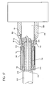
FIG. 17 is a side cutaway view along the centerline of a connector with a nut member connecting a coaxial cable to a terminal and covered by a seal ring, or boot, as disclosed herein. - Reference will now be made in detail to the present preferred embodiment(s) of the invention, examples of which are illustrated in the accompanying drawings. Whenever possible, the same reference numerals will be used throughout the drawings to refer to the same or like parts. One embodiment of the nut member of the present invention is shown in
FIG. 1 , and is designated generally throughout by thereference numeral 10. -
FIG. 1 schematically illustrates a perspective view ofnut member 10 for a coaxial cable connector as disclosed herein.FIG. 2 schematically illustrates an end view ofnut member 10.FIG. 3 shows a side view of an embodiment of acoaxial cable connector 100 as disclosed herein.FIG. 4 shows a side cutaway view of the connector ofFIG. 3 in a cable insertion state.FIG. 5 shows a side cutaway view along the centerline of the connector ofFIG. 3 in a cable-installed state, wherein theconnector 100 connects acable 310 to a threadedterminal 320. Thecable 310 comprises a center conductor (typically metal) 312, a dielectric 314, a braid and/orfoil 316, andjacket 318. - Referring to
FIGS. 1-5 , thenut member 10 comprises anut body 12 having a central longitudinal axis A-A and acentral hole 14. Thenut body 12 comprises a drivinghead portion 16 and anannular portion 18. - The driving
head portion 16 has arear end 20, afront end 22, anouter side surface 24, and aninner side surface 26 extending from therear end 20 to thefront end 22. The inner side surface 26 (seeFIG. 4 ) defines at least part of thecentral hole 14. Theouter side surface 24 comprises a plurality of oppositely disposedflat sides 26 disposed substantially parallel, preferably parallel, with the central longitudinal axis. Each of theflat sides 26 lies in a respective plane, illustrated inFIG. 2 by dashed lines, disposed at least a minimum radial distance RF from the central longitudinal axis, wherein the planes of respective adjacentflat sides 26 intersect along respectiveapex lines 28, the apex lines being preferably parallel with the central longitudinal axis, disposed at a radial distance Rx from the central longitudinal axis. Adjacentflat sides 26 intersect along corner edges 30 disposed at a maximum radial distance Rc from the central longitudinal axis. The corner edges 30 may be sharp within manufacturing tolerances (i.e. Rc is equal to Rx within manufacturing tolerances), or preferably the corner edges 30 are rounded or shaped. Whether sharp or rounded or shaped, we have found that (Rc-RF)/(RX-RF) > 0.75 in order to promote adequate gripping of thenut member 10 by a wrench. For example, for values of (RC-RF)/(RX-RF) less than 0.75 and using a wrench tool such as Gilbert Security Tool G-SST-US manufactured and distributed by Corning Gilbert Inc., we have found unacceptable ability to be wrench-tightened. For example, for (RC-RF)/(RX-RF) of about 0.70, we found that the wrench tool jumped over the points with minor force, while for (RC-RF)/(RX-RF) of about 0.63, the tool jumped over the points with ease. Lower values of (RC-RF)/(RX-RF) resulted in no nut/tool engagement. Other wrench tools could be used with the nut members disclosed herein. - The
annular portion 18 has arear end 32 disposed at thefront end 22 of the drivinghead portion 16, afront end 34, anouter side surface 36 having a maximum radius RAO less than RF such that a minimum radial offset (RF - RAO) is provided between theouter side surface 24 of the drivinghead portion 16 and theouter side surface 36 of theannular portion 18, and an inner side surface 38 (seeFIG. 4 ) extending from therear end 32 of theannular portion 18 to thefront end 34 of theannular portion 18, theinner side surface 38 of theannular portion 18 defining at least part of thecentral hole 14. Either theinner side surface 26 of the drivinghead portion 16, or theinner side surface 38 of theannular portion 18, or both, has threads 40 (seeFIG. 4 ), i.e. thenut member 10 is internally threaded. - As illustrated by the embodiment in
FIGS. 1 and 2 , each of theflat sides 26 are grooved with alongitudinal groove 42 intermediate adjacent corner edges 30, each of thegrooves 42 having a respective maximum width, wi, and a respective maximum depth. Additional grooves may be provided on one or more of the flat sides 26. In some embodiments, one or moreflat sides 26 are provided with no grooves. - Each grooved
flat side 26 has a respective total groove width Σwi, wherein the respective maximum depth of each of the grooves is not greater than the radial offset between the outer side surfaces 24, 36 of the drivinghead portion 16 and theannular portion 18, that is, for any angular position in a transverse plane that intersects arespective groove 42. Thus, if agroove 42 were situated on aflat side 26 at the midpoint between adjacent corner edges 30, the radial offset would have a minimum value 42 (i.e. RF - RAO) compared to a groove situated closer to one of the corner edges 30. The depth of agroove 42 is its radial depth. - Preferably, none of the
grooves 42 extends to theinner side surface 26 of the drivinghead portion 16 in order to promote environmental sealing between theinner side surface 26 and other surfaces provided by other parts of the connector to which thenut member 10 would become engaged. - In one preferred embodiment, the
inner side surface 26 of the drivinghead portion 16 has threads. In another preferred embodiment, theinner side surface 26 of theannular portion 18 has threads. In yet another preferred embodiment, the inner side surfaces 26 of the drivinghead portion 16 and theinner side surface 38 of theannular portion 18 have threads. - The
central hole 14 may have a substantially constant diameter or a variable diameter. In some preferred embodiments, theinner side surface 26 of the drivinghead portion 16 comprises aflange 44. - As seen in
FIGS. 1 and 2 , none of thegrooves 42 has a maximum depth greater than the minimum radial offset (RF- RAO) between the outer side surfaces 24, 36 of the drivinghead portion 16 and theannular portion 18. The groovedflat sides 26 have alongitudinal groove 42 disposed between adjacent corner edges 30 and closer to thecorner edge 30 in the direction of the threads, as indicated by thearrow 46 inFIG. 1 . Upon tightening of the nut member 10 (or connector 100) onto a threaded terminal, torque can be preferentially applied to the part of theflat sides 26 having thelongitudinal groove 42, whether the torque is provided by a wrench or by hand. - Each grooved
flat side 26 has a transverse width WF and a total groove width Σwi. - In order to promote the ability to finger-tighten or hand-tighten the
nut member 10 onto a threaded terminal, the ratio Σwi / WF is greater than 0.05, more preferably greater than 0.10, even more preferably greater than 0.15, for each of the grooved flat sides in order to allow finger or thumb or hand flesh to engage the depressions provided by thegrooves 42. That is, a sufficient grooved surface area is required to provide adequate grip by the installer, in the event that a wrench is not utilized for tightening. - In order to help provide the strength of the
nut member 10 under tightening via a tool such as a wrench, Σwi / WF is less than 1, preferably less than 0.9, more preferably less than 0.8. In preferred embodiments, Σwi / WF is between 0.05 and 1.0 for each of the groovedflat sides 26. In other preferred embodiments, each groovedflat side 26 has a transverse width WF and a total groove width, and the ratio Σwi / WF is between 0.10 and 0.9 for each of the grooved flat sides. In other preferred embodiments, each groovedflat side 26 has a transverse width WF and a total groove width, and the ratio Σwi / WF is between 0.15 and 0.8 for each of the grooved flat sides. - None of the
grooves 42 has a maximum depth greater than the difference between the minimum radial distance RF from the central longitudinal axis and the maximum radius of theouter side surface 36 of theannular portion 18. - As seen in
FIGS. 1 and 2 , each of thegrooves 42 are spaced away from the corner edges 30 by alinear distance 48 measured along the respectiveflat side 26 of at least 0.10 WF, more preferably by at least 0.12 WF, even more preferably by at least 0.14 WF. - As illustrated in
FIGS. 1 and3 for that embodiment, thegrooves 42 extend from therear end 20 to thefront end 22 of the drivinghead portion 16, and thegrooves 42 extend continuously from therear end 20 to thefront end 22 of the drivinghead portion 16. In other embodiments, one or more grooves may be provided on aflat side 26, wherein the grooves longitudinally extend only partially between the rear end and the front end of the drivinghead portion 16. In other embodiments, a plurality of longitudinally aligned spaced apart grooves (e.g. at least two grooves being aligned end to end but separated by ungrooved surface) are disposed on aflat side 26. Multiple grooves of uniform or nonuniform length may be staggered over one orflat sides 26. - As seen in
FIGS. 1, 2 and3 , none of thelongitudinal grooves 42 extend onto theouter side surface 36 of theannular portion 18. Preferably, theouter side surface 36 of theannular portion 18 has no longitudinal grooves, whether extensions of grooves on the drivinghead portion 16 or otherwise, in order to promote environmental sealing between theouter side surface 36 of theannular portion 18 and a surface of another member used in conjunction with the connector, such as a protective boot. - The
central hole 14 extends through thenut member 10 fromend 20 to end 24, and thecentral hole 14 is centered about the central longitudinal axis A-A. -
FIG. 6 is an end view of theconnector 100 ofFIGS. 3-5 .FIG. 7 is an isometric view of the connector ofFIGS. 3-6 .FIG. 8 is an isometric view of the nut member of the connector ofFIGS. 3-6 . Theconnector 100 can be used for coupling an end of a coaxial cable to a threaded terminal. Theconnector 100 comprises anut member 10, acylindrical body member 102, and apost member 104. Thecylindrical body member 102 has a rear end 106 (adapted to receive the end of the coaxial cable), afront end 108, and acentral hole 110 extending through the cylindrical body from therear end 106 to thefront end 108. Thenut member 10 has acentral hole 110 extending through the nut member. Thenut member 10 engages thefront end 108 of thecylindrical body member 102. Thepost member 104 comprises apost flange 112 and apost shank 114. In both a cable insertion position (prior to securement of theconnector 100 to the coaxial cable as illustrated inFIG. 4 ) and a cable-installed position (as illustrated inFIG. 5 ), thepost member 104 is disposed at least partially within thecentral hole 110 of thecylindrical body member 102 at thefront end 108 of thecylindrical body member 102 and disposed at least partially within thecentral hole 14 of thenut member 10. Thepost member 104 and thecylindrical body member 102 are movable with respect to each other in the cable-insertion position, wherein thepost member 104 and thecylindrical body member 102 are adapted to sandwich a part of the coaxial cable in the cable-installed position. The nut member 10 comprises a nut body 12 having a central longitudinal axis A-A, the nut body 12 comprising: a driving head portion 16 having a rear end 20, a front end 22, an outer side surface 24, and an inner side surface 26 extending from the rear end 20 to the front end 22, the inner side surface 26 defining at least part of the central hole 14 of the nut member 10, the inner side surface 26 comprising an annular collar 44 for rotatably engaging the front end 108 of the cylindrical body member 102, the outer side surface 24 comprising a plurality of oppositely disposed flat sides 26 disposed substantially parallel, preferably parallel, with the central longitudinal axis A-A (the axis preferably being shared by the cylindrical body member 102, the post member 104, and the nut member 10), wherein each of the flat sides lies in a respective plane disposed at least a minimum radial distance RF from the central longitudinal axis, wherein the planes of respective adjacent flat sides 26 intersect along respective apex lines 28, preferably parallel with the central longitudinal axis, disposed at a maximum radial distance Rx from the central longitudinal axis, wherein adjacent flat sides 26 intersect along corner edges 30 disposed at a maximum radial distance Rc from the central longitudinal axis, wherein (Rc - RF)/(RX- RF) > 0.75, and an annular portion 18 having a rear end 32 disposed at the front end 22 of the driving head portion 16, a front end 34, an outer side surface 36 having a maximum radius less than RF such that a minimum radial offset is provided between the outer side surface 24 of the driving head portion 16 and the outer side surface 36 of the annular portion 18, and an inner side surface 38 extending from the rear end 32 of the annular portion 18 to the front end 34 of the annular portion 18, the inner side surface 38 of the annular portion 18 defining at least part of the central hole 14. In the embodiment shown inFIG. 4 , both theinner side surface 26 of the drivinghead portion 16 and theinner side surface 38 of theannular portion 18 havethreads 40 adapted to threadably engage the threaded terminal. Each of theflat sides 26 are grooved with twolongitudinal grooves 42 intermediate adjacent corner edges 30, each of thegrooves 42 having a respective maximum width, wi, and a respective maximum depth, wherein each groovedflat side 26 has a respective total groove width Σwi, wherein the respective maximum depth of each of thegrooves 42 is not greater than the radial offset between the outer side surfaces 24, 36 of the drivinghead portion 16 and theannular portion 18. - The grooves in
FIG. 6 have a generally rectangular shape.FIG. 9 is an end view of a connector 100' as disclosed herein comprising a nut member 10' with rounded grooves 42'.FIG. 10 is an end view of aconnector 100" as disclosed herein comprising anut member 10" with V-shapedgrooves 42". - The nut member disclosed herein may be adapted to various types of coaxial connectors, such as F-type, SMA, ENC, SC and other connectors.
-
FIG. 11 shows a side view of another embodiment of acoaxial cable connector 200 as disclosed herein. Theconnector 200 comprises acylindrical body 202, apost member 204, anut member 210 as disclosed herein, and acompression ring 205. Axial movement of thecylindrical body 202 and thecompression ring 205 toward each other causes thecylindrical sleeve 207 to compress radially inwardly to sandwich the jacket of a coaxial cable between thepost member 204 and thecylindrical sleeve 207. -
FIG. 12 shows a top view of a representative wrench tool-300 such as the Gilbert Security Tool G-SST-US, manufactured and distributed by Coming Gilbert Inc., which is awrench tool 300 suitable for use with coaxial cable connectors having nut members.FIG. 13 is a side view of thetool 300 ofFIG. 12. FIG. 14 is an end view of thetool 300 ofFIGS. 12-13 .Tool 300 comprises a generally C-shapedbody 302 provided with anaxial slot 303 and an innerfastener embracing surface 304 disposed at one end, wherein theinner surface 304 has a contour which mates with a nut member. Theslot 303 is adapted to permit thetool 300 to be slid over acoaxial cable 310 such that thetool 300 and thecable 310 can be oriented with parallel longitudinal axes. Thetool 300 can be used to tighten to a terminal 320, or loosen from a terminal, a nut member which forms part of a connector attached to the end of thecable 310. Preferably thetool 300 comprises contoured innerfastener embracing surfaces 304 at both opposing ends, as illustrated inFIG. 12 . Thetool 300 also comprises ahandle 305 which is preferably pivotally attached to the C-shapedbody 304. -
FIG. 15 is a cutaway cross-sectional side view of thetool 300 ofFIG. 12 (handle not shown) in engagement with anut member 10, as disclosed herein. Thewrench tool 300 is shown engaging the drivinghead portion 16 of anut member 10 of a connector disclosed herein. Thewrench 300 is open-ended and has afastener embracing surface 304 generally complementary to at least a portion of the outer side surface of the drivinghead portion 16 of thenut member 10. -
FIG. 16 is a cutaway cross-sectional side view of thetool 300 ofFIG. 12 (handle not shown) in engagement with aconnector 100, wherein theconnector 100 comprises anut member 10 shown engaging a terminal 320 and theconnector 100 is attached to the end of acoaxial cable 310, as disclosed herein. Theconnector 100 and the terminal 320 are shown in partial cutaway cross-section. A portion of theconnector 100 and a portion of thecable 310 are shown disposed within thetool 300. Thenut member 10 may thus be tightened onto the terminal 320, thereby attaching theconnector 100 to the terminal 320, thereby establishing a physical and electrical contact between thecable 310 and the terminal 320. Thetool 300 may also be used to loosen thenut member 10 from the terminal 320, thereby disengaging theconnector 100 from the terminal 320, thereby disconnecting thecable 310 from the terminal 320. -
FIG. 17 shows a side cutaway view along the centerline of aconnector 100 with anut member 10 connecting acoaxial cable 310 to a terminal 320 and covered by a seal ring, or boot, 330, as disclosed herein. Thecoaxial cable 310 comprises acenter conductor 312 surrounded by a dielectric 314, which is surrounded by an outer conductor such as a foil and/orbraid 316, all of which is encased in ajacket 318. Theconnector 100 is attached to thecable 310 in a cable-installed state wherein theouter conductor 316 and thejacket 318 are sandwiched between thecylindrical body member 102 and theshank 114 of thepost member 104, wherein theshank 114 has been driven between the dielectric 314 and theouter conductor 316. Thenut member 10 has been threaded onto the terminal 320, which was surrounded by a seal ring orboot 330, and tightened. Theinterface 332 between abutting surfaces of theseal ring 330 and theannular portion 18 of thenut member 10 forms an environmental seal. Preferably, a seal is established around an entire circumference of theannular portion 18, for example to prevent moisture from entering theconnector 100 and/orterminal 320. The terminal 320 shown inFIG. 17 comprisesprongs 322 which grip thecenter conductor 312 ofcable 310 to establish a physical and electrical connection. - The driving
head portion 16 of thenut member 10 disclosed herein preferably has a polygonal periphery, for example the hexagonal periphery shown inFIGS. 6-10 . Other embodiments include square, quadrilateral, octagonal, and other shaped peripheries. Preferably the periphery is in the shape of a regular polygon, more preferably a regular hexagon. - The
nut member 10 may be made by any known process. Preferably the grooves on the nut member are formed by a die during extrusion. Preferably no machining of thenut member 10 is performed. In some preferred embodiments, thenut member 10 is made from metal. In other preferred embodiments, thenut member 10 is made from plastic. - It will be apparent to those skilled in the art that various modifications and variations can be made to the present invention without departing from the claims.
Claims (8)
- A nut member for a coaxial cable connector, the nut member comprising a nut body (12) having a central longitudinal axis (A-A) and a central hole (14), the nut body (12) comprising:a driving head portion (16) having a rear end (20), a front end (22), an outer side surface (24), and an inner side surface extending from the rear end (20) to the front end (22), the inner side surface defining at least part of the central hole (14), the outer side surface (24) comprising a plurality of oppositely disposed flat sides (26) disposed substantially parallel with the central longitudinal axis (A-A), wherein each of the flat sides (26) lies in a respective plane disposed at least a minimum radial distance RF from the central longitudinal axis (A-A), wherein the planes of respective adjacent flat sides (26) intersect along respective apex lines (28) disposed at a radial distance RX from the central longitudinal axis (A-A), wherein adjacent flat sides (26) intersect along corner edges (30) disposed at a radial distance Rc from the central longitudinal axis (A-A);characterized in thatthe radial distances RF, Rx and Rc of the driving head portion (16) fulfill the criteria (RC-RF)/(RX-RF) > 0.75;the nut body (12) comprises an annular portion (18) having a rear end (32) disposed at the front end (22) of the driving head portion (16), a front end (34), an outer side surface (36) having a maximum radius RAO less than RF such that a minimum radial offset RF - RAO is provided between the outer side surface (24) of the driving head portion (16) and the outer side surface (36) of the annular portion (18), and an inner side surface (38) extending from the rear end (32) of the annular portion (18) to the front end (34) of the annular portion (18), the inner side surface (38) of the annular portion (18) defining at least part of the central hole (14);at least one of the inner side surface of the driving head portion (16) and the inner side surface (38) of the annular portion (18) has threads (40);at least two of the flat sides (26) are each grooved with one single longitudinal groove (42) disposed between adjacent corner edges (30) and closer to the corner edge (30) in the direction of the threads (40) upon which torque is applied when tightening the nut, each of said grooves (42) having a respective maximum width, wi, and a respective maximum depth, wherein each grooved flat side (26) has a respective total groove width Σwi ,the respective maximum depth of each of the grooves (42) is not greater than the radial offset between the outer side surfaces of the driving head portion (16) and the annular portion (18);
- The nut member of claim 1 wherein none of the grooves (42) has a maximum depth greater than the minimum radial offset between the outer side surfaces of the driving head portion (16) and the annular portion (18).
- The nut member of claim 1 wherein each grooved flat side (26) has a transverse width WF and a total groove width, and the ratio ∑wi / WF > 0.05 for each of the grooved flat sides.
- The nut member of claim 1 wherein each grooved flat side (26) has a transverse width WF and a total groove width, and the ratio ∑wi / WF > 0.10 for each of the grooved flat sides.
- The nut member of claim 1 wherein each grooved flat side (26) has a transverse width WF and a total groove width, and the ratio ∑Wi / WF > 0.15 for each of the grooved flat sides.
- The nut member of claim 1 wherein each grooved flat side (26) has a transverse width WF and a total groove width, and the ratio ∑wi / WF is between 0.05 and 1.0 for each of the grooved flat sides.
- The nut member of claim 1 wherein each grooved flat side (26) has a transverse width WF and a total groove width, and the ratio ∑wi / WF is between 0.10 and 0.9 for each of the grooved flat sides.
- The nut member of claim 1 wherein each grooved flat side (26) has a transverse width WF and a total groove width, and the ratio ∑wi / WF is between 0.15 and 0.8 for each of the grooved flat sides.
Applications Claiming Priority (2)
| Application Number | Priority Date | Filing Date | Title |
|---|---|---|---|
| US10/823,333 US6887102B1 (en) | 2004-04-13 | 2004-04-13 | Coaxial cable connector and nut member |
| PCT/US2005/010564 WO2005101585A1 (en) | 2004-04-13 | 2005-03-29 | Coaxial cable connector and nut member |
Publications (2)
| Publication Number | Publication Date |
|---|---|
| EP1735877A1 EP1735877A1 (en) | 2006-12-27 |
| EP1735877B1 true EP1735877B1 (en) | 2010-07-21 |
Family
ID=34523361
Family Applications (1)
| Application Number | Title | Priority Date | Filing Date |
|---|---|---|---|
| EP05730267A Expired - Lifetime EP1735877B1 (en) | 2004-04-13 | 2005-03-29 | Coaxial cable connector and nut member |
Country Status (11)
| Country | Link |
|---|---|
| US (1) | US6887102B1 (en) |
| EP (1) | EP1735877B1 (en) |
| JP (1) | JP4625072B2 (en) |
| KR (1) | KR101059295B1 (en) |
| CN (1) | CN100521395C (en) |
| AT (1) | ATE475210T1 (en) |
| CA (1) | CA2561546C (en) |
| DE (1) | DE602005022425D1 (en) |
| DK (1) | DK1735877T3 (en) |
| TW (1) | TWI265662B (en) |
| WO (1) | WO2005101585A1 (en) |
Families Citing this family (45)
| Publication number | Priority date | Publication date | Assignee | Title |
|---|---|---|---|---|
| US7114990B2 (en) | 2005-01-25 | 2006-10-03 | Corning Gilbert Incorporated | Coaxial cable connector with grounding member |
| US7147509B1 (en) * | 2005-07-29 | 2006-12-12 | Corning Gilbert Inc. | Coaxial connector torque aid |
| DE102006001440B4 (en) * | 2006-01-10 | 2010-06-24 | Phoenix Contact Gmbh & Co. Kg | Electrical connector |
| WO2007126711A1 (en) * | 2006-03-29 | 2007-11-08 | Corning Gilbert Inc. | Coaxial connector and coaxial cable connector assembly and related method |
| US7618276B2 (en) * | 2007-06-20 | 2009-11-17 | Amphenol Corporation | Connector assembly with gripping sleeve |
| US7544094B1 (en) * | 2007-12-20 | 2009-06-09 | Amphenol Corporation | Connector assembly with gripping sleeve |
| US7946199B2 (en) * | 2008-07-27 | 2011-05-24 | The Jumper Shop, Llc | Coaxial cable connector nut rotation aid |
| USD600210S1 (en) | 2008-11-21 | 2009-09-15 | Thomas & Betts International, Inc. | Coaxial cable connector in open position |
| US8029316B2 (en) | 2008-11-21 | 2011-10-04 | Belden Inc. | Hand tightenable coaxial cable connector |
| TWM372901U (en) * | 2009-09-18 | 2010-01-21 | Gourmet Equipment Taiwan Corp | Lock element |
| TWI549386B (en) | 2010-04-13 | 2016-09-11 | 康寧吉伯特公司 | Coaxial connector with inhibited ingress and improved grounding |
| US8556656B2 (en) | 2010-10-01 | 2013-10-15 | Belden, Inc. | Cable connector with sliding ring compression |
| TWI558022B (en) | 2010-10-27 | 2016-11-11 | 康寧吉伯特公司 | Push-on cable connector with a coupler and retention and release mechanism |
| US8414313B2 (en) | 2011-07-12 | 2013-04-09 | Belden Inc. | Security shield and tool |
| US9190744B2 (en) | 2011-09-14 | 2015-11-17 | Corning Optical Communications Rf Llc | Coaxial cable connector with radio frequency interference and grounding shield |
| US20130072057A1 (en) | 2011-09-15 | 2013-03-21 | Donald Andrew Burris | Coaxial cable connector with integral radio frequency interference and grounding shield |
| US9028276B2 (en) | 2011-12-06 | 2015-05-12 | Pct International, Inc. | Coaxial cable continuity device |
| US9362634B2 (en) | 2011-12-27 | 2016-06-07 | Perfectvision Manufacturing, Inc. | Enhanced continuity connector |
| US9136654B2 (en) | 2012-01-05 | 2015-09-15 | Corning Gilbert, Inc. | Quick mount connector for a coaxial cable |
| US9407016B2 (en) | 2012-02-22 | 2016-08-02 | Corning Optical Communications Rf Llc | Coaxial cable connector with integral continuity contacting portion |
| US9287659B2 (en) | 2012-10-16 | 2016-03-15 | Corning Optical Communications Rf Llc | Coaxial cable connector with integral RFI protection |
| US9147963B2 (en) | 2012-11-29 | 2015-09-29 | Corning Gilbert Inc. | Hardline coaxial connector with a locking ferrule |
| US9153911B2 (en) | 2013-02-19 | 2015-10-06 | Corning Gilbert Inc. | Coaxial cable continuity connector |
| US9172154B2 (en) | 2013-03-15 | 2015-10-27 | Corning Gilbert Inc. | Coaxial cable connector with integral RFI protection |
| US10290958B2 (en) | 2013-04-29 | 2019-05-14 | Corning Optical Communications Rf Llc | Coaxial cable connector with integral RFI protection and biasing ring |
| EP3000154B1 (en) | 2013-05-20 | 2019-05-01 | Corning Optical Communications RF LLC | Coaxial cable connector with integral rfi protection |
| US9548557B2 (en) | 2013-06-26 | 2017-01-17 | Corning Optical Communications LLC | Connector assemblies and methods of manufacture |
| US9048599B2 (en) | 2013-10-28 | 2015-06-02 | Corning Gilbert Inc. | Coaxial cable connector having a gripping member with a notch and disposed inside a shell |
| WO2016073309A1 (en) | 2014-11-03 | 2016-05-12 | Corning Optical Communications Rf Llc | Coaxial cable connector with integral rfi protection |
| DE102014224450B4 (en) * | 2014-11-28 | 2016-09-29 | Ifm Electronic Gmbh | Circular connector for industrial applications with a screw element |
| US9590287B2 (en) | 2015-02-20 | 2017-03-07 | Corning Optical Communications Rf Llc | Surge protected coaxial termination |
| US10033122B2 (en) | 2015-02-20 | 2018-07-24 | Corning Optical Communications Rf Llc | Cable or conduit connector with jacket retention feature |
| US9564695B2 (en) | 2015-02-24 | 2017-02-07 | Perfectvision Manufacturing, Inc. | Torque sleeve for use with coaxial cable connector |
| US10211547B2 (en) | 2015-09-03 | 2019-02-19 | Corning Optical Communications Rf Llc | Coaxial cable connector |
| US9525220B1 (en) | 2015-11-25 | 2016-12-20 | Corning Optical Communications LLC | Coaxial cable connector |
| USD815046S1 (en) | 2016-08-30 | 2018-04-10 | Steren Electronics International, Llc | Sleeve for cable connector |
| US9837777B1 (en) | 2016-08-30 | 2017-12-05 | Steren Electronics International, Llc | Expandable cable connector torque adapter |
| US9929498B2 (en) | 2016-09-01 | 2018-03-27 | Times Fiber Communications, Inc. | Connector assembly with torque sleeve |
| US9929499B2 (en) | 2016-09-01 | 2018-03-27 | Amphenol Corporation | Connector assembly with torque sleeve |
| US10439302B2 (en) | 2017-06-08 | 2019-10-08 | Pct International, Inc. | Connecting device for connecting and grounding coaxial cable connectors |
| TWM569954U (en) * | 2018-04-25 | 2018-11-11 | 光紅建聖股份有限公司 | Coaxial cable connector |
| KR102441347B1 (en) * | 2020-06-22 | 2022-09-07 | 한화시스템 주식회사 | Jigs for fastening cable assemblies and methods for fastening cable assemblies |
| US12034264B2 (en) | 2021-03-31 | 2024-07-09 | Corning Optical Communications Rf Llc | Coaxial cable connector assemblies with outer conductor engagement features and methods for using the same |
| CN113431835A (en) * | 2021-08-03 | 2021-09-24 | 厦门同恒金属有限公司 | Anti-dismantling fastener |
| US12272918B1 (en) * | 2024-07-18 | 2025-04-08 | Kevin King | Hand-manipulated tool for assembling solar electrical connectors |
Family Cites Families (31)
| Publication number | Priority date | Publication date | Assignee | Title |
|---|---|---|---|---|
| US522144A (en) | 1894-06-26 | Nut-lock | ||
| US989294A (en) | 1910-11-23 | 1911-04-11 | Frank E Sackrider | Nut-lock. |
| US3198230A (en) | 1964-06-26 | 1965-08-03 | Lamson And Sessions Company | Lock nut |
| US3342233A (en) | 1965-06-25 | 1967-09-19 | Michael M Meisel | Lock nut |
| US3511118A (en) | 1968-05-06 | 1970-05-12 | Vernon R Mitchell | Head configuration for a threaded fastening member |
| US3512447A (en) | 1968-09-09 | 1970-05-19 | Rudolph Marion Vaughn | Frangible nut fastener |
| US3641848A (en) | 1969-06-30 | 1972-02-15 | George W Franks | Cylindrical nut and wrench |
| US4043369A (en) | 1976-03-11 | 1977-08-23 | Abernethy Robert R | Edge deformable lock nut |
| DE2843770A1 (en) * | 1978-10-06 | 1980-04-10 | Spinner Georg | Union nut for HF coaxial cable - has spanner surface with axial ribs and grooves at corners of hexagon for gripping with fingers |
| US4462652A (en) | 1981-08-03 | 1984-07-31 | The Bendix Corporation | Coupling nut for an electrical connector |
| US4479689A (en) | 1982-09-30 | 1984-10-30 | The Bendix Corporation | Coupling nut for an electrical connector |
| US4478473A (en) | 1982-09-30 | 1984-10-23 | The Bendix Corporation | Coupling nut for an electrical connector |
| US4457469A (en) | 1982-09-30 | 1984-07-03 | The Bendix Corporation | Coupling nut for an electrical connector |
| US4457572A (en) | 1982-09-30 | 1984-07-03 | The Bendix Corporation | Coupling nut for an electrical connector |
| US4478474A (en) | 1982-09-30 | 1984-10-23 | The Bendix Corporation | Coupling nut for an electrical connector |
| JPS5982977U (en) * | 1982-11-26 | 1984-06-05 | 日本電気株式会社 | coaxial connector |
| USD296579S (en) | 1986-01-06 | 1988-07-05 | Suncast Corporation | Ring nut for garden hose connector |
| JPS6391982A (en) * | 1986-10-03 | 1988-04-22 | 株式会社 潤工社 | Phase adjusting coaxial connector |
| US4877271A (en) | 1987-04-01 | 1989-10-31 | Rexnord Inc. | Hydraulic connector |
| US5049017A (en) | 1990-05-21 | 1991-09-17 | Pac Fasteners | Laminated nut with anti-spin off structure and method of making nut |
| US5564938A (en) * | 1995-02-06 | 1996-10-15 | Shenkal; Yuval | Lock device for use with coaxial cable connection |
| US6153830A (en) * | 1997-08-02 | 2000-11-28 | John Mezzalingua Associates, Inc. | Connector and method of operation |
| US5967852A (en) * | 1998-01-15 | 1999-10-19 | Adc Telecommunications, Inc. | Repairable connector and method |
| US6113410A (en) * | 1998-10-27 | 2000-09-05 | Lucent Technologies Inc. | RF connector lock |
| US6220804B1 (en) | 1999-03-24 | 2001-04-24 | R B & W Corporation | Self-piercing clinch nut |
| CN103178365B (en) * | 2000-05-10 | 2018-04-17 | 托马斯及贝茨国际股份有限公司 | Coaxial connector with detachable locking sleeve |
| JP3892329B2 (en) * | 2002-03-29 | 2007-03-14 | Uro電子工業株式会社 | Coaxial connector |
| US6790081B2 (en) * | 2002-05-08 | 2004-09-14 | Corning Gilbert Inc. | Sealed coaxial cable connector and related method |
| CA2428893C (en) * | 2002-05-31 | 2007-12-18 | Thomas & Betts International, Inc. | Connector for hard-line coaxial cable |
| US6716062B1 (en) * | 2002-10-21 | 2004-04-06 | John Mezzalingua Associates, Inc. | Coaxial cable F connector with improved RFI sealing |
| US6712631B1 (en) * | 2002-12-04 | 2004-03-30 | Timothy L. Youtsey | Internally locking coaxial connector |
-
2004
- 2004-04-13 US US10/823,333 patent/US6887102B1/en not_active Expired - Lifetime
-
2005
- 2005-03-29 KR KR1020067023421A patent/KR101059295B1/en not_active Expired - Fee Related
- 2005-03-29 AT AT05730267T patent/ATE475210T1/en not_active IP Right Cessation
- 2005-03-29 CA CA2561546A patent/CA2561546C/en not_active Expired - Lifetime
- 2005-03-29 JP JP2007508370A patent/JP4625072B2/en not_active Expired - Fee Related
- 2005-03-29 EP EP05730267A patent/EP1735877B1/en not_active Expired - Lifetime
- 2005-03-29 DK DK05730267.1T patent/DK1735877T3/en active
- 2005-03-29 CN CNB2005800110246A patent/CN100521395C/en not_active Expired - Fee Related
- 2005-03-29 DE DE602005022425T patent/DE602005022425D1/en not_active Expired - Lifetime
- 2005-03-29 WO PCT/US2005/010564 patent/WO2005101585A1/en not_active Ceased
- 2005-04-09 TW TW094111309A patent/TWI265662B/en not_active IP Right Cessation
Also Published As
| Publication number | Publication date |
|---|---|
| ATE475210T1 (en) | 2010-08-15 |
| CN100521395C (en) | 2009-07-29 |
| US6887102B1 (en) | 2005-05-03 |
| JP2007533103A (en) | 2007-11-15 |
| WO2005101585A1 (en) | 2005-10-27 |
| CA2561546A1 (en) | 2005-10-27 |
| KR101059295B1 (en) | 2011-08-24 |
| KR20060130780A (en) | 2006-12-19 |
| TWI265662B (en) | 2006-11-01 |
| CN101015093A (en) | 2007-08-08 |
| CA2561546C (en) | 2012-10-23 |
| DE602005022425D1 (en) | 2010-09-02 |
| TW200637083A (en) | 2006-10-16 |
| EP1735877A1 (en) | 2006-12-27 |
| DK1735877T3 (en) | 2010-11-08 |
| JP4625072B2 (en) | 2011-02-02 |
Similar Documents
| Publication | Publication Date | Title |
|---|---|---|
| US6887102B1 (en) | Coaxial cable connector and nut member | |
| US7074081B2 (en) | Connector capable of firmly engaging an electric cord or an cable | |
| EP1504497B1 (en) | Sealed coaxial cable connector and related method | |
| US7128603B2 (en) | Sealed coaxial cable connector and related method | |
| US7077699B2 (en) | Axial compression electrical connector | |
| EP1095429B1 (en) | F-connector with deformable body and compression ring | |
| US6776657B1 (en) | Connector capable of connecting to coaxial cable without using tool | |
| US7121872B1 (en) | Electrical connector with interference collar | |
| US7207820B1 (en) | Connecting assembly for a cable and method of connecting a cable | |
| US20040194585A1 (en) | Coaxial cable thumb socket | |
| US5547404A (en) | Fixed spacer hot line tap | |
| CN101371403A (en) | Coaxial cable connector | |
| CA2618334C (en) | Electrical wiring | |
| US7011547B1 (en) | Connector of coaxial cables | |
| CA2114474C (en) | Cable clamp with stress distributing grip | |
| CN220963910U (en) | Coaxial connector with torsion | |
| CA2556115C (en) | Indoor/outdoor coaxial cable connector | |
| JPH09115566A (en) | Conductor connection sleeve | |
| JPH0313690B2 (en) |
Legal Events
| Date | Code | Title | Description |
|---|---|---|---|
| PUAI | Public reference made under article 153(3) epc to a published international application that has entered the european phase |
Free format text: ORIGINAL CODE: 0009012 |
|
| 17P | Request for examination filed |
Effective date: 20060928 |
|
| AK | Designated contracting states |
Kind code of ref document: A1 Designated state(s): AT BE BG CH CY CZ DE DK EE ES FI FR GB GR HU IE IS IT LI LT LU MC NL PL PT RO SE SI SK TR |
|
| DAX | Request for extension of the european patent (deleted) | ||
| 17Q | First examination report despatched |
Effective date: 20071213 |
|
| GRAP | Despatch of communication of intention to grant a patent |
Free format text: ORIGINAL CODE: EPIDOSNIGR1 |
|
| GRAS | Grant fee paid |
Free format text: ORIGINAL CODE: EPIDOSNIGR3 |
|
| GRAA | (expected) grant |
Free format text: ORIGINAL CODE: 0009210 |
|
| AK | Designated contracting states |
Kind code of ref document: B1 Designated state(s): AT BE BG CH CY CZ DE DK EE ES FI FR GB GR HU IE IS IT LI LT LU MC NL PL PT RO SE SI SK TR |
|
| REG | Reference to a national code |
Ref country code: GB Ref legal event code: FG4D |
|
| REG | Reference to a national code |
Ref country code: CH Ref legal event code: EP |
|
| REG | Reference to a national code |
Ref country code: IE Ref legal event code: FG4D |
|
| REF | Corresponds to: |
Ref document number: 602005022425 Country of ref document: DE Date of ref document: 20100902 Kind code of ref document: P |
|
| REG | Reference to a national code |
Ref country code: NL Ref legal event code: T3 |
|
| REG | Reference to a national code |
Ref country code: DK Ref legal event code: T3 |
|
| LTIE | Lt: invalidation of european patent or patent extension |
Effective date: 20100721 |
|
| PG25 | Lapsed in a contracting state [announced via postgrant information from national office to epo] |
Ref country code: AT Free format text: LAPSE BECAUSE OF FAILURE TO SUBMIT A TRANSLATION OF THE DESCRIPTION OR TO PAY THE FEE WITHIN THE PRESCRIBED TIME-LIMIT Effective date: 20100721 Ref country code: FI Free format text: LAPSE BECAUSE OF FAILURE TO SUBMIT A TRANSLATION OF THE DESCRIPTION OR TO PAY THE FEE WITHIN THE PRESCRIBED TIME-LIMIT Effective date: 20100721 Ref country code: LT Free format text: LAPSE BECAUSE OF FAILURE TO SUBMIT A TRANSLATION OF THE DESCRIPTION OR TO PAY THE FEE WITHIN THE PRESCRIBED TIME-LIMIT Effective date: 20100721 |
|
| PG25 | Lapsed in a contracting state [announced via postgrant information from national office to epo] |
Ref country code: PT Free format text: LAPSE BECAUSE OF FAILURE TO SUBMIT A TRANSLATION OF THE DESCRIPTION OR TO PAY THE FEE WITHIN THE PRESCRIBED TIME-LIMIT Effective date: 20101122 Ref country code: IS Free format text: LAPSE BECAUSE OF FAILURE TO SUBMIT A TRANSLATION OF THE DESCRIPTION OR TO PAY THE FEE WITHIN THE PRESCRIBED TIME-LIMIT Effective date: 20101121 Ref country code: SI Free format text: LAPSE BECAUSE OF FAILURE TO SUBMIT A TRANSLATION OF THE DESCRIPTION OR TO PAY THE FEE WITHIN THE PRESCRIBED TIME-LIMIT Effective date: 20100721 Ref country code: PL Free format text: LAPSE BECAUSE OF FAILURE TO SUBMIT A TRANSLATION OF THE DESCRIPTION OR TO PAY THE FEE WITHIN THE PRESCRIBED TIME-LIMIT Effective date: 20100721 Ref country code: CY Free format text: LAPSE BECAUSE OF FAILURE TO SUBMIT A TRANSLATION OF THE DESCRIPTION OR TO PAY THE FEE WITHIN THE PRESCRIBED TIME-LIMIT Effective date: 20100721 Ref country code: BG Free format text: LAPSE BECAUSE OF FAILURE TO SUBMIT A TRANSLATION OF THE DESCRIPTION OR TO PAY THE FEE WITHIN THE PRESCRIBED TIME-LIMIT Effective date: 20101021 |
|
| PG25 | Lapsed in a contracting state [announced via postgrant information from national office to epo] |
Ref country code: GR Free format text: LAPSE BECAUSE OF FAILURE TO SUBMIT A TRANSLATION OF THE DESCRIPTION OR TO PAY THE FEE WITHIN THE PRESCRIBED TIME-LIMIT Effective date: 20101022 Ref country code: BE Free format text: LAPSE BECAUSE OF FAILURE TO SUBMIT A TRANSLATION OF THE DESCRIPTION OR TO PAY THE FEE WITHIN THE PRESCRIBED TIME-LIMIT Effective date: 20100721 Ref country code: SE Free format text: LAPSE BECAUSE OF FAILURE TO SUBMIT A TRANSLATION OF THE DESCRIPTION OR TO PAY THE FEE WITHIN THE PRESCRIBED TIME-LIMIT Effective date: 20100721 |
|
| PLBE | No opposition filed within time limit |
Free format text: ORIGINAL CODE: 0009261 |
|
| STAA | Information on the status of an ep patent application or granted ep patent |
Free format text: STATUS: NO OPPOSITION FILED WITHIN TIME LIMIT |
|
| PG25 | Lapsed in a contracting state [announced via postgrant information from national office to epo] |
Ref country code: RO Free format text: LAPSE BECAUSE OF FAILURE TO SUBMIT A TRANSLATION OF THE DESCRIPTION OR TO PAY THE FEE WITHIN THE PRESCRIBED TIME-LIMIT Effective date: 20100721 Ref country code: CZ Free format text: LAPSE BECAUSE OF FAILURE TO SUBMIT A TRANSLATION OF THE DESCRIPTION OR TO PAY THE FEE WITHIN THE PRESCRIBED TIME-LIMIT Effective date: 20100721 Ref country code: SK Free format text: LAPSE BECAUSE OF FAILURE TO SUBMIT A TRANSLATION OF THE DESCRIPTION OR TO PAY THE FEE WITHIN THE PRESCRIBED TIME-LIMIT Effective date: 20100721 Ref country code: EE Free format text: LAPSE BECAUSE OF FAILURE TO SUBMIT A TRANSLATION OF THE DESCRIPTION OR TO PAY THE FEE WITHIN THE PRESCRIBED TIME-LIMIT Effective date: 20100721 Ref country code: IT Free format text: LAPSE BECAUSE OF FAILURE TO SUBMIT A TRANSLATION OF THE DESCRIPTION OR TO PAY THE FEE WITHIN THE PRESCRIBED TIME-LIMIT Effective date: 20100721 |
|
| PGFP | Annual fee paid to national office [announced via postgrant information from national office to epo] |
Ref country code: FR Payment date: 20110331 Year of fee payment: 7 Ref country code: NL Payment date: 20110329 Year of fee payment: 7 |
|
| 26N | No opposition filed |
Effective date: 20110426 |
|
| PG25 | Lapsed in a contracting state [announced via postgrant information from national office to epo] |
Ref country code: ES Free format text: LAPSE BECAUSE OF FAILURE TO SUBMIT A TRANSLATION OF THE DESCRIPTION OR TO PAY THE FEE WITHIN THE PRESCRIBED TIME-LIMIT Effective date: 20101101 |
|
| REG | Reference to a national code |
Ref country code: DE Ref legal event code: R097 Ref document number: 602005022425 Country of ref document: DE Effective date: 20110426 |
|
| PG25 | Lapsed in a contracting state [announced via postgrant information from national office to epo] |
Ref country code: MC Free format text: LAPSE BECAUSE OF NON-PAYMENT OF DUE FEES Effective date: 20110331 |
|
| REG | Reference to a national code |
Ref country code: CH Ref legal event code: PL |
|
| REG | Reference to a national code |
Ref country code: IE Ref legal event code: MM4A |
|
| PG25 | Lapsed in a contracting state [announced via postgrant information from national office to epo] |
Ref country code: IE Free format text: LAPSE BECAUSE OF NON-PAYMENT OF DUE FEES Effective date: 20110329 Ref country code: CH Free format text: LAPSE BECAUSE OF NON-PAYMENT OF DUE FEES Effective date: 20110331 Ref country code: LI Free format text: LAPSE BECAUSE OF NON-PAYMENT OF DUE FEES Effective date: 20110331 |
|
| REG | Reference to a national code |
Ref country code: NL Ref legal event code: V1 Effective date: 20121001 |
|
| REG | Reference to a national code |
Ref country code: FR Ref legal event code: ST Effective date: 20121130 |
|
| PG25 | Lapsed in a contracting state [announced via postgrant information from national office to epo] |
Ref country code: FR Free format text: LAPSE BECAUSE OF NON-PAYMENT OF DUE FEES Effective date: 20120402 |
|
| PG25 | Lapsed in a contracting state [announced via postgrant information from national office to epo] |
Ref country code: NL Free format text: LAPSE BECAUSE OF NON-PAYMENT OF DUE FEES Effective date: 20121001 |
|
| PG25 | Lapsed in a contracting state [announced via postgrant information from national office to epo] |
Ref country code: LU Free format text: LAPSE BECAUSE OF NON-PAYMENT OF DUE FEES Effective date: 20110329 |
|
| PG25 | Lapsed in a contracting state [announced via postgrant information from national office to epo] |
Ref country code: TR Free format text: LAPSE BECAUSE OF FAILURE TO SUBMIT A TRANSLATION OF THE DESCRIPTION OR TO PAY THE FEE WITHIN THE PRESCRIBED TIME-LIMIT Effective date: 20100721 |
|
| PG25 | Lapsed in a contracting state [announced via postgrant information from national office to epo] |
Ref country code: HU Free format text: LAPSE BECAUSE OF FAILURE TO SUBMIT A TRANSLATION OF THE DESCRIPTION OR TO PAY THE FEE WITHIN THE PRESCRIBED TIME-LIMIT Effective date: 20100721 |
|
| REG | Reference to a national code |
Ref country code: DE Ref legal event code: R082 Ref document number: 602005022425 Country of ref document: DE Representative=s name: QUERMANN STURM WEILNAU PATENTANWAELTE PARTNERS, DE Ref country code: DE Ref legal event code: R081 Ref document number: 602005022425 Country of ref document: DE Owner name: CORNING OPTICAL COMMUNICATIONS RF LLC (N.D.GES, US Free format text: FORMER OWNER: CORNING GILBERT LLC, GLENDALE, AZ, US Ref country code: DE Ref legal event code: R081 Ref document number: 602005022425 Country of ref document: DE Owner name: CORNING OPTICAL COMMUNICATIONS RF LLC (N.D.GES, US Free format text: FORMER OWNER: CORNING GILBERT INC., GLENDALE, ARIZ., US Ref country code: DE Ref legal event code: R082 Ref document number: 602005022425 Country of ref document: DE Representative=s name: PATENTANWAELTE STURM WEILNAU FRANKE PARTNERSCH, DE Ref country code: DE Ref legal event code: R081 Ref document number: 602005022425 Country of ref document: DE Owner name: CORNING OPTICAL COMMUNICATIONS APS, DK Free format text: FORMER OWNER: CORNING GILBERT LLC, GLENDALE, AZ, US Ref country code: DE Ref legal event code: R081 Ref document number: 602005022425 Country of ref document: DE Owner name: CORNING OPTICAL COMMUNICATIONS APS, DK Free format text: FORMER OWNER: CORNING GILBERT INC., GLENDALE, ARIZ., US Ref country code: DE Ref legal event code: R081 Ref document number: 602005022425 Country of ref document: DE Owner name: AMPHENOL CABELCON APS, DK Free format text: FORMER OWNER: CORNING GILBERT INC., GLENDALE, ARIZ., US Ref country code: DE Ref legal event code: R081 Ref document number: 602005022425 Country of ref document: DE Owner name: AMPHENOL CABELCON APS, DK Free format text: FORMER OWNER: CORNING GILBERT LLC, GLENDALE, AZ, US |
|
| REG | Reference to a national code |
Ref country code: GB Ref legal event code: 732E Free format text: REGISTERED BETWEEN 20210218 AND 20210224 |
|
| REG | Reference to a national code |
Ref country code: DE Ref legal event code: R082 Ref document number: 602005022425 Country of ref document: DE Representative=s name: PATENTANWAELTE STURM WEILNAU FRANKE PARTNERSCH, DE Ref country code: DE Ref legal event code: R081 Ref document number: 602005022425 Country of ref document: DE Owner name: CORNING OPTICAL COMMUNICATIONS APS, DK Free format text: FORMER OWNER: CORNING OPTICAL COMMUNICATIONS RF LLC (N.D.GES. DES STAATES DELAWARE), GLENDALE, AZ, US Ref country code: DE Ref legal event code: R081 Ref document number: 602005022425 Country of ref document: DE Owner name: AMPHENOL CABELCON APS, DK Free format text: FORMER OWNER: CORNING OPTICAL COMMUNICATIONS RF LLC (N.D.GES. DES STAATES DELAWARE), GLENDALE, AZ, US |
|
| REG | Reference to a national code |
Ref country code: GB Ref legal event code: 732E Free format text: REGISTERED BETWEEN 20210617 AND 20210623 |
|
| REG | Reference to a national code |
Ref country code: DE Ref legal event code: R082 Ref document number: 602005022425 Country of ref document: DE Representative=s name: BECK & ROESSIG EUROPEAN PATENT ATTORNEYS, DE Ref country code: DE Ref legal event code: R081 Ref document number: 602005022425 Country of ref document: DE Owner name: AMPHENOL CABELCON APS, DK Free format text: FORMER OWNER: CORNING OPTICAL COMMUNICATIONS APS, VORDINGBORG, DK Ref country code: DE Ref legal event code: R082 Ref document number: 602005022425 Country of ref document: DE Representative=s name: BECK & ROESSIG - EUROPEAN PATENT ATTORNEYS, DE |
|
| P01 | Opt-out of the competence of the unified patent court (upc) registered |
Effective date: 20230601 |
|
| PGFP | Annual fee paid to national office [announced via postgrant information from national office to epo] |
Ref country code: DE Payment date: 20240130 Year of fee payment: 20 Ref country code: GB Payment date: 20240108 Year of fee payment: 20 |
|
| PGFP | Annual fee paid to national office [announced via postgrant information from national office to epo] |
Ref country code: DK Payment date: 20240314 Year of fee payment: 20 |
|
| REG | Reference to a national code |
Ref country code: DE Ref legal event code: R071 Ref document number: 602005022425 Country of ref document: DE |
|
| REG | Reference to a national code |
Ref country code: DK Ref legal event code: EUP Expiry date: 20250329 |
|
| REG | Reference to a national code |
Ref country code: GB Ref legal event code: PE20 Expiry date: 20250328 |
|
| PG25 | Lapsed in a contracting state [announced via postgrant information from national office to epo] |
Ref country code: GB Free format text: LAPSE BECAUSE OF EXPIRATION OF PROTECTION Effective date: 20250328 |