EP1735535B1 - Impeller lock assembly and method - Google Patents
Impeller lock assembly and method Download PDFInfo
- Publication number
- EP1735535B1 EP1735535B1 EP05725896.4A EP05725896A EP1735535B1 EP 1735535 B1 EP1735535 B1 EP 1735535B1 EP 05725896 A EP05725896 A EP 05725896A EP 1735535 B1 EP1735535 B1 EP 1735535B1
- Authority
- EP
- European Patent Office
- Prior art keywords
- impeller
- shaft
- engagement tab
- ring member
- engages
- Prior art date
- Legal status (The legal status is an assumption and is not a legal conclusion. Google has not performed a legal analysis and makes no representation as to the accuracy of the status listed.)
- Expired - Lifetime
Links
- 238000000034 method Methods 0.000 title claims description 9
- 230000013011 mating Effects 0.000 claims description 3
- 125000006850 spacer group Chemical group 0.000 description 3
- 230000008569 process Effects 0.000 description 2
- 230000004075 alteration Effects 0.000 description 1
- 230000008878 coupling Effects 0.000 description 1
- 238000010168 coupling process Methods 0.000 description 1
- 238000005859 coupling reaction Methods 0.000 description 1
- 238000004519 manufacturing process Methods 0.000 description 1
- 230000007246 mechanism Effects 0.000 description 1
- 238000012986 modification Methods 0.000 description 1
- 230000004048 modification Effects 0.000 description 1
Images


Classifications
-
- F—MECHANICAL ENGINEERING; LIGHTING; HEATING; WEAPONS; BLASTING
- F04—POSITIVE - DISPLACEMENT MACHINES FOR LIQUIDS; PUMPS FOR LIQUIDS OR ELASTIC FLUIDS
- F04D—NON-POSITIVE-DISPLACEMENT PUMPS
- F04D29/00—Details, component parts, or accessories
- F04D29/18—Rotors
- F04D29/20—Mounting rotors on shafts
-
- F—MECHANICAL ENGINEERING; LIGHTING; HEATING; WEAPONS; BLASTING
- F04—POSITIVE - DISPLACEMENT MACHINES FOR LIQUIDS; PUMPS FOR LIQUIDS OR ELASTIC FLUIDS
- F04D—NON-POSITIVE-DISPLACEMENT PUMPS
- F04D1/00—Radial-flow pumps, e.g. centrifugal pumps; Helico-centrifugal pumps
- F04D1/06—Multi-stage pumps
- F04D1/063—Multi-stage pumps of the vertically split casing type
-
- F—MECHANICAL ENGINEERING; LIGHTING; HEATING; WEAPONS; BLASTING
- F04—POSITIVE - DISPLACEMENT MACHINES FOR LIQUIDS; PUMPS FOR LIQUIDS OR ELASTIC FLUIDS
- F04D—NON-POSITIVE-DISPLACEMENT PUMPS
- F04D17/00—Radial-flow pumps, e.g. centrifugal pumps; Helico-centrifugal pumps
- F04D17/08—Centrifugal pumps
- F04D17/10—Centrifugal pumps for compressing or evacuating
- F04D17/12—Multi-stage pumps
- F04D17/122—Multi-stage pumps the individual rotor discs being, one for each stage, on a common shaft and axially spaced, e.g. conventional centrifugal multi- stage compressors
-
- F—MECHANICAL ENGINEERING; LIGHTING; HEATING; WEAPONS; BLASTING
- F04—POSITIVE - DISPLACEMENT MACHINES FOR LIQUIDS; PUMPS FOR LIQUIDS OR ELASTIC FLUIDS
- F04D—NON-POSITIVE-DISPLACEMENT PUMPS
- F04D29/00—Details, component parts, or accessories
- F04D29/26—Rotors specially for elastic fluids
- F04D29/266—Rotors specially for elastic fluids mounting compressor rotors on shafts
Definitions
- the impeller lock assembly 10 and impeller lock 18 of the present invention may be applied to any impeller-shaft connection in rotating turbomachinery, where it is desirable to limit axial movement of the impeller relative to the shaft during operation of such rotating turbomachinery.
- the impeller lock assembly 10 and impeller lock 18 have particular application in sleeveless impeller design, wherein an impeller is provided on a rotating shaft with nothing in front or behind the impeller to limit its axial movement on the shaft.
- the impeller lock 18 of the present invention may be incorporated into such sleeveless impeller configurations as a safety mechanism to prevent the impeller from moving on the shaft and potentially damaging other components of the rotating turbomachine into which the impeller is incorporated.
- such sleeveless impeller designs have the impeller shrink-fitted onto the shaft, which may be eliminated by application of the impeller lock assembly 10 and impeller lock 18 of the present invention.
Landscapes
- Engineering & Computer Science (AREA)
- Mechanical Engineering (AREA)
- General Engineering & Computer Science (AREA)
- Structures Of Non-Positive Displacement Pumps (AREA)
- Supercharger (AREA)
Description
- The present invention relates generally to rotating turbomachinery, such as turbochargers, and, more particularly, to an improved arrangement for mounting and securing an impeller wheel of such turbomachinery to a rotating shaft and limiting axial movement of the impeller wheel on the shaft during operation of the turbomachine.
- In rotating turbomachinery such as turbochargers, impeller wheels are mounted to a rotating shaft, which is driven at high rotational speed. For example, a diesel engine turbocharger typically includes a turbine which drives a shaft and a compressor mounted for rotation on the shaft opposite the turbine wheel. The compressor typically includes an impeller wheel mounted for rotation on the shaft. The impeller wheel is driven at high rotational speeds by the rotating shaft during operation of the turbocharger. Numerous mounting arrangements are known in the field of rotating turbomachinery, also referred to herein generally as turbomachinery, for mounting and/or securing an impeller wheel to a rotating shaft. A few examples of such mounting arrangements are discussed herein.
-
U.S. Pat. No. 6,481,917 to Chen et al. discloses an arrangement for mounting an impeller wheel, such as a turbine or compressor wheel, on a shaft. In the mounting arrangement disclosed by this patent, the impeller wheel is held in place on the shaft by a plurality of clamping rings. One of the clamping rings engages a recess in the hub of the impeller wheel, while a second clamping ring engages a similarly formed recess at the opposite end of the impeller wheel hub. The first clamping ring is held in place against the impeller wheel by a threaded nut and engages a plurality of Belleville spring washers. -
U.S. Pat. No. 5,961,246 to Mitsubori discloses a simple coupling bushing for joining an impeller wheel to a shaft. -
U.S. Pat. No. 5,163,816 to Goetzke et al. discloses another example of a mounting arrangement for mounting an impeller wheel on a drive shaft. The mounting arrangement disclosed by this patent includes a two-piece spacer which is used to secure the impeller wheel to the drive shaft. The drive shaft includes a journal. The two-piece spacer is provided between the journal and the impeller wheel. The two-piece spacer includes a flange member and an annular locking ring. The annular locking ring is disposed in a recess formed in the flange member, and between the flange member and the impeller wheel. The locking ring includes a projection that engages a recess in the impeller wheel. The projection engages a tubular sleeve provided between the impeller wheel and the shaft. The annular locking ring further engages spline recesses formed in the drive shaft. -
U.S. Pat. No. 3,884,595 to Herrick discloses a further example of an impeller wheel and shaft mounting arrangement. In the mounting arrangement disclosed by this patent, the shaft is provided with a keyway which receives a key. A hub portion of the impeller wheel is also provided with a keyway, which receives the same key. The key prevents relative rotation between the impeller wheel and the shaft. -
U.S. Pat. No. 2,960,939 to Buschhom et al. discloses a rotor attachment arrangement for centrifugal pumps. In the attachment arrangement disclosed by this patent, a locking ring is provided in an annular groove in a pump shaft. The locking ring extends into a recess formed in a shaft-protecting sleeve positioned about the pump shaft. The locking ring prevents movement of the pump shaft relative to the sleeve by engaging a shoulder formed in the sleeve and a key formed on the pump shaft. - The
US-A 2,526,751 relates to a mounting device for pump impellers. In a mounting for pump impeller, a rotary shaft, an impeller on the shaft and having a bore, a pair of sleeve segments on the shaft extending at one end into the bore and having chords greater than the diameter of the bore to cause the tensing of the segments for maintaining them in firm frictional engagement with the surface of the bore and an abutment on the shaft for the other ends of the segments.
While numerous attachment or mounting arrangements are known in the art for connecting an impeller wheel to a rotating shaft, a continuing need still exists in the field of rotating turbomachinery for improved impeller-shaft mounting or attachment methods, particularly those that are simple to manufacture and install in such rotating turbomachinery. A specific need exists for an improved mounting arrangement for mounting and/or securing an impeller wheel to a rotating shaft that will limit axial movement of the impeller wheel on the shaft, which occurs during operation of the turbomachine. - The foregoing needs are fulfilled by an impeller lock according to claims 1-3 and an impeller lock assembly according to claims 4-12.
- The present invention is further directed to a method of limiting axial movement of an impeller on a shaft according to claims 13-16.
- Further details and advantages of the present invention will become apparent when reading the detailed description herein, in conjunction with the drawings.
-
-
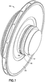
FIG. 1 is a perspective view of an impeller lock assembly in accordance with the present invention; -
FIG. 2 is a perspective and partially-exploded view of the impeller lock assembly ofFIG. 1 , revealing an impeller wheel, shaft, shaft sleeve, and impeller lock of the assembly; -
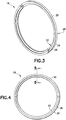
FIG. 3 is a perspective view of the impeller lock of the impeller lock assembly shown inFIGS. 1 and2 ; -
FIG. 4 is a front view of the impeller lock of the impeller lock assembly shown inFIGS. 1 and2 ; -
FIG. 5 is a transverse cross-sectional view taken along lines 5-5 inFIG. 4 ; and -
FIG. 6 is a detailed cross-sectional view showing the connection between the impeller wheel, shaft, and shaft sleeve, which is secured by the impeller lock of the present invention. - The present invention is generally directed to an arrangement or structure for securing an impeller wheel to a rotating shaft. Such an arrangement or structure is used in rotating turbomachinery such as turbochargers, wherein an impeller wheel is mounted to a rotating shaft driven at high speeds. Referring to
FIGS. 1 and2 , animpeller lock assembly 10 of the present invention is shown. Theimpeller lock assembly 10 generally includes ashaft 12, such as a rotating shaft used to drive a compressor, an impeller wheel 14 (hereinafter "impeller 14"), and ashaft sleeve 16 disposed on theshaft 12 and spaced axially from theimpeller 14. Theimpeller lock assembly 10 further includes animpeller lock 18 disposed on theshaft 12, generally between theimpeller 14 andshaft sleeve 16. - The
impeller lock 18 andshaft sleeve 16 are generally adapted to secure theimpeller 14 to theshaft 12. In particular, theimpeller lock 18 is provided on theshaft 12 to limit axial movement of theimpeller 14 on theshaft 12, and theshaft sleeve 16 is adapted to secure theimpeller lock 18 to theshaft 12. Such axial movement is caused by differences in gas pressure acting on theimpeller 14 during operation of a rotating turbomachine, such as a compressor, incorporating theimpeller 14. The forces generated by such gas pressure differences during operation of the rotating turbomachine cause theimpeller 14 to move axially on theshaft 12. Theimpeller lock assembly 10 andimpeller lock 18 of the present invention solve this problem by limiting the axial movement of theimpeller 14 on theshaft 12. - Referring to
FIGS. 1-6 , theimpeller lock 18 is generally formed by aring member 20, which is preferably a split-ring member as shown inFIG. 3 . Thering member 20 includes aninner side 22 and anouter side 24. As shown inFIG. 6 , thering member 20 further includesopposing sides impeller 14 and theshaft sleeve 16, respectively.FIG. 6 further shows theimpeller lock 18 andshaft sleeve 16 connecting and securing theimpeller 14 to theshaft 12. - The body of the
ring member 20 defines a plurality of engagement tabs for engaging theshaft 12,impeller 14, andshaft sleeve 16. In particular, the body of thering member 20 defines a first,circumferential engagement tab 31 adapted to engage theimpeller 14, a second,circumferential engagement tab 32 adapted to engage theshaft 12, and a third,circumferential engagement tab 33 adapted to engage theshaft sleeve 16. Theshaft sleeve 16 cooperates with or engages thethird engagement tab 33 to secure thering member 20 comprising theimpeller lock 18 to theshaft 12, such that axial movement of theimpeller 14 on theshaft 12 is limited during rotation of theimpeller 14 andshaft 12. - As shown in
FIG. 6 , the first andsecond engagement tabs inner side 22 of thering member 20, while theouter side 24 of thering member 20 is formed to be substantially planar, and substantially coincident with anouter surface 27 of theshaft sleeve 16, and anouter surface 29 of the hub of theimpeller 14, which is the portion of theimpeller 14 that is fitted to theshaft 12 as is known in the art.FIGS. 5 and 6 further show that thefirst engagement tab 31 may be formed as ahook 34 with aprong 36. Theprong 36 engages theimpeller 14, as shown inFIG. 6 . Thehook 34 andprong 36 comprising thefirst engagement tab 31 preferably engage a mating hook 38 andprong 40 defined by the body of theimpeller 14, to secure theimpeller 14 to theshaft 12. - The body of the
ring member 20 is preferably configured such that thesecond engagement tab 32 lies along a radial axis L of a transverse cross-section through thering member 20, as shown inFIG. 5 . Thethird engagement tab 33 extends along an axis S1 oriented substantially perpendicular to the radial axis L of the transverse cross-section. Further, as indicated previously, thefirst engagement tab 31 may be formed as ahook 34 with aprong 36 adapted to engage theimpeller 14. Theprong 36 of thefirst engagement tab 31 may extend along an axis S2 oriented substantially parallel to the radial axis L of the transverse cross-section. - The first and
second engagement tabs impeller 14 to theshaft 12, and limit axial movement of theimpeller 14 relative to theshaft 12 when theshaft sleeve 16 is applied to theshaft 12 to secure thering member 20 to theshaft 12. To secure the connection of theimpeller 14 to theshaft 12, thesecond engagement tab 32 engages acircumferential groove 42 in theshaft 12, and thefirst engagement tab 31 engages the body of theimpeller 14 in the manner discussed previously. Thus, with thefirst engagement tab 31 engaged with the body of theimpeller 14, and thesecond engagement tab 32 engaged in thegroove 42 in theshaft 12, theimpeller 14 is mounted to theshaft 12 and limited in axial movement relative to theshaft 12, once theshaft sleeve 16 is applied to theshaft 12. As indicated previously, theshaft sleeve 16 is generally adapted to cooperate with or receive thethird engagement tab 33, and secures thering member 20 to theshaft 12 via thethird engagement tab 33. - The
third engagement tab 33 is shaped in a similar manner to the first andsecond engagement tabs shaft sleeve 16. In particular, thethird engagement tab 33 engages or is received in acircumferential groove 43 defined in theshaft sleeve 16. Theshaft sleeve 16 provides the radial force or pressure needed to maintain thering member 20 of theimpeller lock 18 engaged with theshaft 12 via thesecond engagement tab 32, which allows theimpeller lock 18 to operate or function to limit the axial movement of theimpeller 14 on theshaft 12 during operation of theimpeller 14. - The steps for assembling the
impeller lock assembly 10 of the present invention will now be discussed with continued reference toFIGS. 1-6 . Theimpeller lock assembly 10 is assembled by first positioning theimpeller 14 on theshaft 12. Theimpeller 14 may be shrunk-fit to theshaft 12 in a known manner in the art. Shrink-fitting is a known process in the art and relates to forming an interference fit between the hub of theimpeller 14 andshaft 12. In particular, the shaft opening in the hub of theimpeller 14 is purposely made smaller than the diameter of theshaft 12. Theimpeller 14 is then heated so that this opening is enlarged so that theimpeller 14 may be fitted onto theshaft 12. Once theimpeller 14 and hub thereof cool, the hub of theimpeller 14 "shrinks" onto theshaft 12, forming an interference engagement therewith. - The
impeller lock 18, preferably in the form of the split-ring ring member 20, is then positioned about theshaft 12, adjacent theimpeller 14. Thering member 20 is preferably provided with a split-ring body so that thering member 20 may be positioned about theshaft 12 without having to pass thering member 20 over an end of theshaft 12. Thering member 20 is then engaged with theimpeller 14 andshaft 12. Once thering member 20 is engaged with theimpeller 14 andshaft 12, theshaft sleeve 16 may then be positioned about theshaft 12 and used to secure thering member 20 to theimpeller 14 andshaft 12. In particular, thering member 20 is joined or connected to theshaft 12,impeller 14, andshaft sleeve 16, such that thefirst engagement tab 31 engages theimpeller 14, thesecond engagement tab 32 engages thegroove 42 in theshaft 12, and thethird engagement tab 32 engages the groove orrecess 43 in theshaft sleeve 16. Theshaft sleeve 16 may be shrunk-fit to theshaft 12 in the conventional manner described previously in connection with theimpeller 14, and secures the overall connection between thering member 20 and theimpeller 14 andshaft 12. As discussed previously, theimpeller lock 18, once installed, is adapted to limit the axial movement of theimpeller 14 on theshaft 12 during operation of the turbomachine incorporating theimpeller 14 androtating shaft 12. - The
impeller lock 18 may be connected toshaft 12,impeller 14, andshaft sleeve 16, such that thehook 34 of thefirst engagement tab 31 engages the corresponding hook 38 defined by the body of theimpeller 14. In particular, theprong 36 of thefirst engagement tab 31 may be inserted into the hook 38 defined by the body of theimpeller 14, such that theprong 36 coacts with or engages theprong 40 of the hook 38 defined by the body of theimpeller 14. The shrunk-fit shaft sleeve 16 secures thehook 34 to hook 38 engagement, which is illustrated inFIG. 6 . - The
impeller lock 18 may be adapted to retrofit into an existing impeller-shaft connection for limiting axial movement of a previously-existing impeller on a pre-existing shaft. Assuming that theshaft 12,impeller 14, andshaft sleeve 16 are previously existing components found in a turbomachine such as a compressor, theimpeller lock 18 may be adapted for use with such components by first removing theimpeller 14 andshaft sleeve 16 from theshaft 12, and forming thecircumferential groove 42 in theshaft 12 and thecircumferential groove 43 in theshaft sleeve 16. Next, theimpeller 14 is remounted onto theshaft 12. Theimpeller lock 18 is then applied to the remountedimpeller 14 and theshaft 12 in the manner discussed previously. In particular, thering member 20 is positioned about theshaft 12 such that thefirst engagement tab 31 engages theimpeller 14 and thesecond engagement tab 32 engages thegroove 42 in theshaft 12. Theshaft sleeve 16 is then remounted to theshaft 12, such that thethird engagement tab 33 is received in thegroove 43 in theshaft sleeve 16. Theimpeller 14 andshaft sleeve 16 may be remounted to theshaft 12 by the conventional shrink-fitting process identified previously. - The
impeller lock assembly 10 andimpeller lock 18 of the present invention may be applied to any impeller-shaft connection in rotating turbomachinery, where it is desirable to limit axial movement of the impeller relative to the shaft during operation of such rotating turbomachinery. Theimpeller lock assembly 10 andimpeller lock 18 have particular application in sleeveless impeller design, wherein an impeller is provided on a rotating shaft with nothing in front or behind the impeller to limit its axial movement on the shaft. Theimpeller lock 18 of the present invention may be incorporated into such sleeveless impeller configurations as a safety mechanism to prevent the impeller from moving on the shaft and potentially damaging other components of the rotating turbomachine into which the impeller is incorporated. Typically, such sleeveless impeller designs have the impeller shrink-fitted onto the shaft, which may be eliminated by application of theimpeller lock assembly 10 andimpeller lock 18 of the present invention. - While the present invention was described with reference to preferred embodiments of the impeller lock assembly and impeller lock, those skilled in the art may make modifications and alterations to the present invention without departing from the scope of the invention as defined in the appended claims. Accordingly, the above detailed description is intended to be illustrative rather than restrictive.
Claims (16)
- An impeller lock (18) for limiting axial movement of an impeller (14) on a shaft (12), comprising:a ring member (20) having a body defininga first engagement tab (31) adapted to engage the impeller (14),a second engagement tab (32) adapted to engage the shaft (12) supporting the impeller (14), anda third engagement tab (33) adapted to engage a shaft sleeve (16) disposed about the shaft (12), when the ring member (20) is positioned about the shaft (12) and between the impeller (14) and shaft sleeve (16),characterized in thatthe second engagement tab (32) lies along a radial axis of a transverse cross-section through the ring member (20),the first engagement tab (31) is formed as a hook (34) with a prong (36) adapted to engage the impeller (14), the prong (36) extending along an axis substantially parallel to the radial axis, andthe first and second engagement tabs (31, 32) are provided on an inner side (22) of the ring member (20), while an outer side (24) of the ring member (20) is formed to be substantially planar and substantially coincident with an outer surface (27) of the shaft sleeve (16).
- The impeller lock (18) of claim 1, wherein the third engagement tab (33) extends along an axis substantially perpendicular to the radial axis.
- The impeller lock (18) of claim 1, wherein the ring member (20) comprises a split-ring member (20).
- An impeller lock assembly (10) for limiting axial movement of an impeller (14) on a shaft (12) with an impeller lock according to claim 1, comprising:the shaft (12);the impeller (14) disposed about the shaft (12);a shaft sleeve (16) disposed about the shaft (12) and spaced axially from theimpeller (14);and
the ring member (20) disposed about the shaft (12) between the impeller (14) and shaft sleeve (16), the ring member (20) having a body defining a first engagement tab (31) engaging the impeller (14), a second engagement tab (32) engaging the shaft (12), and a third engagement tab (33) engaging the shaft sleeve (16), the shaft sleeve (16) securing the ring member (20) to the shaft (12) via the third engagement tab (33) such that axial movement of the impeller (14) on the shaft (12) is limited during rotation of the impeller (14). - The impeller lock assembly (10) of claim 4, wherein the third engagement tab extends along an axis substantially perpendicular to the radial axis.
- The impeller lock assembly (10) of claim 4, wherein the first engagement tab (31) is formed as a hook (34) with a prong (36), the prong engaging the impeller (14).
- The. impeller lock assembly (10) of claim 6, wherein the prong (36) engages a mating hook defined by the impeller body.
- The impeller lock assembly (10) of claim 4, wherein the ring member (20) comprises a split-ring member.
- The impeller lock assembly (10) of claim 4, wherein opposing sides of the ring member (20) abut the impeller (14) and shaft sleeve (16).
- The impeller lock assembly (10) of claim 4, wherein the second engagement tab (32) engages a groove in the shaft (12), and the third engagement tab (33) engages a groove in the shaft sleeve (16).
- The impeller lock assembly (10) of claim 4, wherein the second engagement tab (32) engages a groove in the shaft (12).
- The impeller lock assembly (10) of claim 4, wherein the third engagement tab (33) engages a groove in the shaft sleeve (16).
- A method of limiting axial movement of an impeller (14) on a shaft (12), comprising:positioning a ring member (20) about the shaft (12) adjacent the impeller (14), the ring member (20) having a body defining a first engagement tab (31) for engaging the impeller (14), a second engagement tab (32) for engaging the shaft (12), and a third engagement tab (33) for engaging a shaft sleeve (16) to be disposed about the shaft (12);joining the ring member (20) to the impeller (14) and shaft (12), such that the first engagement tab (31) engages the impeller (14) and the second engagement tab (32) engages the shaft (12); andjoining the shaft sleeve (16) to the shaft (12), such that the third engagement tab (33) engages the shaft sleeve (16), the shaft sleeve (16) securing the ring member (20) to the shaft (12) via the third engagement tab (33) such that axial movement of the impeller (14) on the shaft (12) is limited during operation of the impeller (14),wherein the first engagement tab (31) is formed as a hook (34) with a prong (36), such that the prong (36) engages the impeller (14) when the ring member (20) is joined to the impeller (14) and shaft (12), and whereinthe first and second engagement tabs (31, 32) are provided on an inner side (22) of the ring member (20), while an outer side (24) of the ring member (20) is formed to be substantially planar and substantially coincident with an outer surface (27) of the shaft sleeve (16).
- The method of claim 13, wherein the prong (36) engages a mating hook defined by the impeller (14) body.
- The method of claim 13, wherein the second engagement tab (32) engages a groove in the shaft (12).
- The method of claim 13, wherein the third engagement tab (33) engages a groove in the shaft sleeve (16).
Priority Applications (1)
| Application Number | Priority Date | Filing Date | Title |
|---|---|---|---|
| EP12157094.9A EP2472124A3 (en) | 2004-03-24 | 2005-03-17 | Impeller lock assembly and method |
Applications Claiming Priority (2)
| Application Number | Priority Date | Filing Date | Title |
|---|---|---|---|
| US10/807,847 US7018177B2 (en) | 2004-03-24 | 2004-03-24 | Impeller lock assembly and method |
| PCT/US2005/009100 WO2005098238A1 (en) | 2004-03-24 | 2005-03-17 | Impeller lock assembly and method |
Related Child Applications (2)
| Application Number | Title | Priority Date | Filing Date |
|---|---|---|---|
| EP12157094.9A Division-Into EP2472124A3 (en) | 2004-03-24 | 2005-03-17 | Impeller lock assembly and method |
| EP12157094.9A Division EP2472124A3 (en) | 2004-03-24 | 2005-03-17 | Impeller lock assembly and method |
Publications (2)
| Publication Number | Publication Date |
|---|---|
| EP1735535A1 EP1735535A1 (en) | 2006-12-27 |
| EP1735535B1 true EP1735535B1 (en) | 2018-10-10 |
Family
ID=34963156
Family Applications (2)
| Application Number | Title | Priority Date | Filing Date |
|---|---|---|---|
| EP12157094.9A Withdrawn EP2472124A3 (en) | 2004-03-24 | 2005-03-17 | Impeller lock assembly and method |
| EP05725896.4A Expired - Lifetime EP1735535B1 (en) | 2004-03-24 | 2005-03-17 | Impeller lock assembly and method |
Family Applications Before (1)
| Application Number | Title | Priority Date | Filing Date |
|---|---|---|---|
| EP12157094.9A Withdrawn EP2472124A3 (en) | 2004-03-24 | 2005-03-17 | Impeller lock assembly and method |
Country Status (4)
| Country | Link |
|---|---|
| US (1) | US7018177B2 (en) |
| EP (2) | EP2472124A3 (en) |
| JP (1) | JP4664353B2 (en) |
| WO (1) | WO2005098238A1 (en) |
Families Citing this family (20)
| Publication number | Priority date | Publication date | Assignee | Title |
|---|---|---|---|---|
| US7855805B2 (en) * | 2005-09-19 | 2010-12-21 | Silverbrook Research Pty Ltd | Printing a competition entry form using a mobile device |
| US7747280B2 (en) * | 2005-09-19 | 2010-06-29 | Silverbrook Research Pty Ltd | Retrieving a product via a coded surface |
| US7558597B2 (en) * | 2005-09-19 | 2009-07-07 | Silverbrook Research Pty Ltd. | Retrieving a ringtone via a coded surface |
| US7738674B2 (en) * | 2005-09-19 | 2010-06-15 | Silverbrook Research Pty Ltd | Retrieving location data by sensing coded data on a surface |
| US7742755B2 (en) * | 2005-09-19 | 2010-06-22 | Silverbrook Research Pty Ltd | Retrieving a bill via a coded surface |
| US7738919B2 (en) * | 2005-09-19 | 2010-06-15 | Silverbrook Research Pty Ltd | Link object to card |
| US7672664B2 (en) * | 2005-09-19 | 2010-03-02 | Silverbrook Research Pty Ltd | Printing a reminder list using mobile device |
| US7756526B2 (en) * | 2005-09-19 | 2010-07-13 | Silverbrook Research Pty Ltd | Retrieving a web page via a coded surface |
| US7761090B2 (en) * | 2005-09-19 | 2010-07-20 | Silverbrook Research Pty Ltd | Print remotely to a mobile device |
| US7738862B2 (en) * | 2005-09-19 | 2010-06-15 | Silverbrook Research Pty Ltd | Retrieve information via card on mobile device |
| US7621442B2 (en) | 2005-09-19 | 2009-11-24 | Silverbrook Research Pty Ltd | Printing a subscription using a mobile device |
| US8224004B2 (en) | 2006-09-08 | 2012-07-17 | Phonak Ag | Programmable remote control |
| US20090179388A1 (en) | 2008-01-15 | 2009-07-16 | Uhlenkamp Brian J | Hygienic Coupling and Fitting Seal System |
| KR101188512B1 (en) | 2010-06-10 | 2012-10-05 | 윌로펌프 주식회사 | Fluid machine |
| FR3002295B1 (en) * | 2013-02-20 | 2016-07-01 | Jspm - Jeumont Systemes De Pompes Et De Mecanismes | PUMP COMPRISING A SCREEN FOR PROTECTING THE PUMP WHEEL AGAINST A FLOW OF A COOLING FLUID ALONG THE HUB OF THE WHEEL |
| CN105570189B (en) | 2014-10-31 | 2020-08-18 | 特灵国际有限公司 | System and method for securing an impeller to a compressor shaft |
| US11041504B2 (en) | 2015-12-03 | 2021-06-22 | Mitsubishi Heavy Industries Compressor Corporation | Rotor of centrifugal compressor, centrifugal compressor, and method for manufacturing rotor of centrifugal compressor |
| CN107339253A (en) * | 2017-06-08 | 2017-11-10 | 三联泵业股份有限公司 | A kind of double-suction pump impeller axial positioning structure |
| IT201800011099A1 (en) * | 2018-12-14 | 2020-06-14 | Nuovo Pignone Tecnologie Srl | PROPANE DE-HYDROGENATION SYSTEM WITH A SINGLE BOX REACTOR EFFLUENT COMPRESSOR AND METHOD |
| WO2022039723A1 (en) | 2020-08-18 | 2022-02-24 | Halliburton Energy Services, Inc. | New impeller locking method |
Family Cites Families (25)
| Publication number | Priority date | Publication date | Assignee | Title |
|---|---|---|---|---|
| DE499929C (en) * | 1930-06-14 | Bbc Brown Boveri & Cie | Fastening of disks on shaft passing through the hub | |
| US2526751A (en) | 1949-05-27 | 1950-10-24 | Ingersoll Rand Co | Mounting device for pump impellers |
| US2892646A (en) | 1954-07-26 | 1959-06-30 | Jabsco Pump Co | Impeller-shaft connection |
| US2960939A (en) | 1958-03-10 | 1960-11-22 | Firm Amag Hilpert Pegnitzhutte | Rotor attachment for centrifugal pumps |
| US3131956A (en) | 1960-05-31 | 1964-05-05 | Thompson Ramo Wooldridge Inc | Removable hub insert |
| US3061342A (en) | 1961-01-24 | 1962-10-30 | Allis Chalmers Mfg Co | Locking and removal device for impellers |
| DE1453784B2 (en) | 1962-01-17 | 1970-02-12 | Klein, Schanzlin & Becker AG, 67IO Frankenthal | Impeller attachment for centrifugal pumps |
| US3246607A (en) * | 1963-07-29 | 1966-04-19 | Ford Motor Co | Impeller |
| US3387768A (en) | 1966-04-08 | 1968-06-11 | Rotron Mfg Co | Fastener |
| NO120916B (en) | 1968-11-25 | 1970-12-21 | Kongsberg Vapenfab As | |
| US3531216A (en) | 1968-12-23 | 1970-09-29 | Allis Chalmers Mfg Co | Shaft attaching means for pump impeller |
| US3715176A (en) | 1971-09-01 | 1973-02-06 | Carrier Corp | Turbo machine rotor structure |
| US3884595A (en) | 1974-05-15 | 1975-05-20 | Dresser Ind | Impeller and shaft assembly |
| DE2457231C2 (en) * | 1974-12-04 | 1976-11-25 | Motoren Turbinen Union | IMPELLER FOR A FAST RUNNING TURBO MACHINE |
| US4363603A (en) | 1980-04-14 | 1982-12-14 | Met-Pro Corporation | Pump impeller assembly with anti-rotation device |
| CS251416B1 (en) | 1985-08-12 | 1987-07-16 | Josef Trnka | Runner's fastening on pump's shaft |
| US4767233A (en) | 1987-03-20 | 1988-08-30 | Dresser Industries, Inc. | Impeller mounting apparatus |
| DE3816796A1 (en) | 1988-05-17 | 1989-11-30 | Kempten Elektroschmelz Gmbh | MECHANICAL CLUTCH |
| US4986733A (en) * | 1989-10-30 | 1991-01-22 | Allied-Signal, Inc. | Turbocharger compressor wheel assembly with boreless hub compressor wheel |
| JPH0544576Y2 (en) | 1990-06-20 | 1993-11-12 | ||
| US5163816A (en) | 1991-07-12 | 1992-11-17 | General Motors Corporation | Wheel lock, centering and drive means and turbocharger impeller combination |
| JP3777648B2 (en) | 1996-04-03 | 2006-05-24 | 石川島播磨重工業株式会社 | Impeller fastening structure |
| US6435832B1 (en) | 2000-04-27 | 2002-08-20 | Chemineer, Inc. | Hub assembly |
| US6481917B1 (en) | 2000-05-02 | 2002-11-19 | Honeywell International Inc. | Tie-boltless shaft lock-up mechanism |
| US6896479B2 (en) * | 2003-04-08 | 2005-05-24 | General Motors Corporation | Turbocharger rotor |
-
2004
- 2004-03-24 US US10/807,847 patent/US7018177B2/en not_active Expired - Lifetime
-
2005
- 2005-03-17 EP EP12157094.9A patent/EP2472124A3/en not_active Withdrawn
- 2005-03-17 JP JP2007505026A patent/JP4664353B2/en not_active Expired - Lifetime
- 2005-03-17 WO PCT/US2005/009100 patent/WO2005098238A1/en not_active Ceased
- 2005-03-17 EP EP05725896.4A patent/EP1735535B1/en not_active Expired - Lifetime
Non-Patent Citations (1)
| Title |
|---|
| None * |
Also Published As
| Publication number | Publication date |
|---|---|
| US20050214125A1 (en) | 2005-09-29 |
| WO2005098238A1 (en) | 2005-10-20 |
| US7018177B2 (en) | 2006-03-28 |
| JP4664353B2 (en) | 2011-04-06 |
| EP2472124A2 (en) | 2012-07-04 |
| EP1735535A1 (en) | 2006-12-27 |
| EP2472124A3 (en) | 2016-01-20 |
| JP2007530859A (en) | 2007-11-01 |
Similar Documents
| Publication | Publication Date | Title |
|---|---|---|
| US7018177B2 (en) | Impeller lock assembly and method | |
| EP0202188B1 (en) | Two stage turbine rotor assembly | |
| US7909578B2 (en) | Turbo machine, compressor impeller used for turbo machine, and method of manufacturing turbo machine | |
| CA2457467C (en) | Turbocharger rotor | |
| EP1413766B1 (en) | Compressor wheel assembly | |
| CA2503930C (en) | Gas turbine engine variable vane assembly | |
| WO2014107161A1 (en) | Seal assembly for arranging between a stator and a rotor | |
| WO1993002278A1 (en) | Compressor wheel and shaft assembly for turbocharger | |
| EP2565398B1 (en) | Shaft assembly for a gas turbine engine | |
| EP4163475A1 (en) | Rotor assembly for a gas turbine engine and method for assembling same | |
| US20190178381A1 (en) | Face seal arrangement with air load force balance recovery for improved failure mitigation strategies | |
| CN111868353A (en) | Cross key anti-rotation spacer | |
| EP3527801B1 (en) | Pressure balanced secondary seal | |
| CA2970382A1 (en) | Shroud housing supported by vane segments | |
| EP3561239B1 (en) | Wedge adapter seal | |
| EP3569818B1 (en) | Support ring with thermal heat shield for case flanges | |
| US7318704B2 (en) | Gas turbine engine structure | |
| EP0203877B1 (en) | Turbine module assembly device | |
| JPH10299407A (en) | Gas turbine engine rotor | |
| CN113544361B (en) | Gas turbine for twin-rotor aircraft | |
| CN221591565U (en) | Adapter and assembly for torque transfer between a first rotatable member and a second rotatable member | |
| EP4737684A2 (en) | Shaft assembly for a gas turbine engine | |
| RU2773854C2 (en) | Rotation-preventing spacer with transverse keys | |
| EP4551824A1 (en) | Coupling joints to interconnect and transmit rotational torque between adjacent impeller bodies in a turbomachine | |
| CN121408367A (en) | bearings |
Legal Events
| Date | Code | Title | Description |
|---|---|---|---|
| PUAI | Public reference made under article 153(3) epc to a published international application that has entered the european phase |
Free format text: ORIGINAL CODE: 0009012 |
|
| 17P | Request for examination filed |
Effective date: 20061006 |
|
| AK | Designated contracting states |
Kind code of ref document: A1 Designated state(s): AT BE BG CH CY CZ DE DK EE ES FI FR GB GR HU IE IS IT LI LT LU MC NL PL PT RO SE SI SK TR |
|
| DAX | Request for extension of the european patent (deleted) | ||
| 17Q | First examination report despatched |
Effective date: 20100226 |
|
| REG | Reference to a national code |
Ref country code: DE Ref legal event code: R079 Ref document number: 602005054747 Country of ref document: DE Free format text: PREVIOUS MAIN CLASS: F04D0029200000 Ipc: F04D0001060000 |
|
| GRAP | Despatch of communication of intention to grant a patent |
Free format text: ORIGINAL CODE: EPIDOSNIGR1 |
|
| STAA | Information on the status of an ep patent application or granted ep patent |
Free format text: STATUS: GRANT OF PATENT IS INTENDED |
|
| RIC1 | Information provided on ipc code assigned before grant |
Ipc: F04D 1/06 20060101AFI20180119BHEP Ipc: F04D 29/20 20060101ALI20180119BHEP Ipc: F04D 29/26 20060101ALI20180119BHEP Ipc: F04D 17/10 20060101ALI20180119BHEP |
|
| INTG | Intention to grant announced |
Effective date: 20180208 |
|
| GRAJ | Information related to disapproval of communication of intention to grant by the applicant or resumption of examination proceedings by the epo deleted |
Free format text: ORIGINAL CODE: EPIDOSDIGR1 |
|
| STAA | Information on the status of an ep patent application or granted ep patent |
Free format text: STATUS: EXAMINATION IS IN PROGRESS |
|
| GRAP | Despatch of communication of intention to grant a patent |
Free format text: ORIGINAL CODE: EPIDOSNIGR1 |
|
| STAA | Information on the status of an ep patent application or granted ep patent |
Free format text: STATUS: GRANT OF PATENT IS INTENDED |
|
| INTC | Intention to grant announced (deleted) | ||
| INTG | Intention to grant announced |
Effective date: 20180507 |
|
| GRAS | Grant fee paid |
Free format text: ORIGINAL CODE: EPIDOSNIGR3 |
|
| GRAJ | Information related to disapproval of communication of intention to grant by the applicant or resumption of examination proceedings by the epo deleted |
Free format text: ORIGINAL CODE: EPIDOSDIGR1 |
|
| GRAL | Information related to payment of fee for publishing/printing deleted |
Free format text: ORIGINAL CODE: EPIDOSDIGR3 |
|
| STAA | Information on the status of an ep patent application or granted ep patent |
Free format text: STATUS: EXAMINATION IS IN PROGRESS |
|
| GRAR | Information related to intention to grant a patent recorded |
Free format text: ORIGINAL CODE: EPIDOSNIGR71 |
|
| STAA | Information on the status of an ep patent application or granted ep patent |
Free format text: STATUS: GRANT OF PATENT IS INTENDED |
|
| GRAA | (expected) grant |
Free format text: ORIGINAL CODE: 0009210 |
|
| STAA | Information on the status of an ep patent application or granted ep patent |
Free format text: STATUS: THE PATENT HAS BEEN GRANTED |
|
| INTC | Intention to grant announced (deleted) | ||
| AK | Designated contracting states |
Kind code of ref document: B1 Designated state(s): AT BE BG CH CY CZ DE DK EE ES FI FR GB GR HU IE IS IT LI LT LU MC NL PL PT RO SE SI SK TR |
|
| INTG | Intention to grant announced |
Effective date: 20180904 |
|
| REG | Reference to a national code |
Ref country code: GB Ref legal event code: FG4D |
|
| REG | Reference to a national code |
Ref country code: CH Ref legal event code: EP Ref country code: AT Ref legal event code: REF Ref document number: 1051562 Country of ref document: AT Kind code of ref document: T Effective date: 20181015 |
|
| REG | Reference to a national code |
Ref country code: IE Ref legal event code: FG4D |
|
| REG | Reference to a national code |
Ref country code: DE Ref legal event code: R096 Ref document number: 602005054747 Country of ref document: DE |
|
| REG | Reference to a national code |
Ref country code: CH Ref legal event code: NV Representative=s name: SCHMAUDER AND PARTNER AG PATENT- UND MARKENANW, CH |
|
| REG | Reference to a national code |
Ref country code: NL Ref legal event code: FP |
|
| REG | Reference to a national code |
Ref country code: LT Ref legal event code: MG4D |
|
| REG | Reference to a national code |
Ref country code: AT Ref legal event code: MK05 Ref document number: 1051562 Country of ref document: AT Kind code of ref document: T Effective date: 20181010 |
|
| PG25 | Lapsed in a contracting state [announced via postgrant information from national office to epo] |
Ref country code: FI Free format text: LAPSE BECAUSE OF FAILURE TO SUBMIT A TRANSLATION OF THE DESCRIPTION OR TO PAY THE FEE WITHIN THE PRESCRIBED TIME-LIMIT Effective date: 20181010 Ref country code: IS Free format text: LAPSE BECAUSE OF FAILURE TO SUBMIT A TRANSLATION OF THE DESCRIPTION OR TO PAY THE FEE WITHIN THE PRESCRIBED TIME-LIMIT Effective date: 20190210 Ref country code: LT Free format text: LAPSE BECAUSE OF FAILURE TO SUBMIT A TRANSLATION OF THE DESCRIPTION OR TO PAY THE FEE WITHIN THE PRESCRIBED TIME-LIMIT Effective date: 20181010 Ref country code: BG Free format text: LAPSE BECAUSE OF FAILURE TO SUBMIT A TRANSLATION OF THE DESCRIPTION OR TO PAY THE FEE WITHIN THE PRESCRIBED TIME-LIMIT Effective date: 20190110 Ref country code: PL Free format text: LAPSE BECAUSE OF FAILURE TO SUBMIT A TRANSLATION OF THE DESCRIPTION OR TO PAY THE FEE WITHIN THE PRESCRIBED TIME-LIMIT Effective date: 20181010 Ref country code: ES Free format text: LAPSE BECAUSE OF FAILURE TO SUBMIT A TRANSLATION OF THE DESCRIPTION OR TO PAY THE FEE WITHIN THE PRESCRIBED TIME-LIMIT Effective date: 20181010 Ref country code: AT Free format text: LAPSE BECAUSE OF FAILURE TO SUBMIT A TRANSLATION OF THE DESCRIPTION OR TO PAY THE FEE WITHIN THE PRESCRIBED TIME-LIMIT Effective date: 20181010 |
|
| PGFP | Annual fee paid to national office [announced via postgrant information from national office to epo] |
Ref country code: CZ Payment date: 20190227 Year of fee payment: 15 |
|
| PG25 | Lapsed in a contracting state [announced via postgrant information from national office to epo] |
Ref country code: PT Free format text: LAPSE BECAUSE OF FAILURE TO SUBMIT A TRANSLATION OF THE DESCRIPTION OR TO PAY THE FEE WITHIN THE PRESCRIBED TIME-LIMIT Effective date: 20190210 Ref country code: GR Free format text: LAPSE BECAUSE OF FAILURE TO SUBMIT A TRANSLATION OF THE DESCRIPTION OR TO PAY THE FEE WITHIN THE PRESCRIBED TIME-LIMIT Effective date: 20190111 Ref country code: SE Free format text: LAPSE BECAUSE OF FAILURE TO SUBMIT A TRANSLATION OF THE DESCRIPTION OR TO PAY THE FEE WITHIN THE PRESCRIBED TIME-LIMIT Effective date: 20181010 |
|
| REG | Reference to a national code |
Ref country code: DE Ref legal event code: R097 Ref document number: 602005054747 Country of ref document: DE |
|
| PG25 | Lapsed in a contracting state [announced via postgrant information from national office to epo] |
Ref country code: DK Free format text: LAPSE BECAUSE OF FAILURE TO SUBMIT A TRANSLATION OF THE DESCRIPTION OR TO PAY THE FEE WITHIN THE PRESCRIBED TIME-LIMIT Effective date: 20181010 |
|
| PLBE | No opposition filed within time limit |
Free format text: ORIGINAL CODE: 0009261 |
|
| STAA | Information on the status of an ep patent application or granted ep patent |
Free format text: STATUS: NO OPPOSITION FILED WITHIN TIME LIMIT |
|
| PG25 | Lapsed in a contracting state [announced via postgrant information from national office to epo] |
Ref country code: SK Free format text: LAPSE BECAUSE OF FAILURE TO SUBMIT A TRANSLATION OF THE DESCRIPTION OR TO PAY THE FEE WITHIN THE PRESCRIBED TIME-LIMIT Effective date: 20181010 Ref country code: RO Free format text: LAPSE BECAUSE OF FAILURE TO SUBMIT A TRANSLATION OF THE DESCRIPTION OR TO PAY THE FEE WITHIN THE PRESCRIBED TIME-LIMIT Effective date: 20181010 Ref country code: EE Free format text: LAPSE BECAUSE OF FAILURE TO SUBMIT A TRANSLATION OF THE DESCRIPTION OR TO PAY THE FEE WITHIN THE PRESCRIBED TIME-LIMIT Effective date: 20181010 |
|
| 26N | No opposition filed |
Effective date: 20190711 |
|
| PG25 | Lapsed in a contracting state [announced via postgrant information from national office to epo] |
Ref country code: SI Free format text: LAPSE BECAUSE OF FAILURE TO SUBMIT A TRANSLATION OF THE DESCRIPTION OR TO PAY THE FEE WITHIN THE PRESCRIBED TIME-LIMIT Effective date: 20181010 Ref country code: MC Free format text: LAPSE BECAUSE OF FAILURE TO SUBMIT A TRANSLATION OF THE DESCRIPTION OR TO PAY THE FEE WITHIN THE PRESCRIBED TIME-LIMIT Effective date: 20181010 |
|
| PG25 | Lapsed in a contracting state [announced via postgrant information from national office to epo] |
Ref country code: LU Free format text: LAPSE BECAUSE OF NON-PAYMENT OF DUE FEES Effective date: 20190317 |
|
| REG | Reference to a national code |
Ref country code: BE Ref legal event code: MM Effective date: 20190331 |
|
| PG25 | Lapsed in a contracting state [announced via postgrant information from national office to epo] |
Ref country code: IE Free format text: LAPSE BECAUSE OF NON-PAYMENT OF DUE FEES Effective date: 20190317 |
|
| PG25 | Lapsed in a contracting state [announced via postgrant information from national office to epo] |
Ref country code: BE Free format text: LAPSE BECAUSE OF NON-PAYMENT OF DUE FEES Effective date: 20190331 |
|
| PG25 | Lapsed in a contracting state [announced via postgrant information from national office to epo] |
Ref country code: TR Free format text: LAPSE BECAUSE OF FAILURE TO SUBMIT A TRANSLATION OF THE DESCRIPTION OR TO PAY THE FEE WITHIN THE PRESCRIBED TIME-LIMIT Effective date: 20181010 |
|
| PG25 | Lapsed in a contracting state [announced via postgrant information from national office to epo] |
Ref country code: CZ Free format text: LAPSE BECAUSE OF NON-PAYMENT OF DUE FEES Effective date: 20200317 |
|
| PG25 | Lapsed in a contracting state [announced via postgrant information from national office to epo] |
Ref country code: CY Free format text: LAPSE BECAUSE OF FAILURE TO SUBMIT A TRANSLATION OF THE DESCRIPTION OR TO PAY THE FEE WITHIN THE PRESCRIBED TIME-LIMIT Effective date: 20181010 |
|
| PG25 | Lapsed in a contracting state [announced via postgrant information from national office to epo] |
Ref country code: HU Free format text: LAPSE BECAUSE OF FAILURE TO SUBMIT A TRANSLATION OF THE DESCRIPTION OR TO PAY THE FEE WITHIN THE PRESCRIBED TIME-LIMIT; INVALID AB INITIO Effective date: 20050317 |
|
| P01 | Opt-out of the competence of the unified patent court (upc) registered |
Effective date: 20230524 |
|
| PGFP | Annual fee paid to national office [announced via postgrant information from national office to epo] |
Ref country code: NL Payment date: 20240108 Year of fee payment: 20 |
|
| PGFP | Annual fee paid to national office [announced via postgrant information from national office to epo] |
Ref country code: DE Payment date: 20231229 Year of fee payment: 20 Ref country code: GB Payment date: 20240108 Year of fee payment: 20 |
|
| PGFP | Annual fee paid to national office [announced via postgrant information from national office to epo] |
Ref country code: IT Payment date: 20240212 Year of fee payment: 20 Ref country code: FR Payment date: 20240103 Year of fee payment: 20 |
|
| PGFP | Annual fee paid to national office [announced via postgrant information from national office to epo] |
Ref country code: CH Payment date: 20240401 Year of fee payment: 20 |
|
| REG | Reference to a national code |
Ref country code: DE Ref legal event code: R071 Ref document number: 602005054747 Country of ref document: DE |
|
| REG | Reference to a national code |
Ref country code: NL Ref legal event code: MK Effective date: 20250316 |
|
| REG | Reference to a national code |
Ref country code: CH Ref legal event code: PL |
|
| REG | Reference to a national code |
Ref country code: GB Ref legal event code: PE20 Expiry date: 20250316 |
|
| PG25 | Lapsed in a contracting state [announced via postgrant information from national office to epo] |
Ref country code: GB Free format text: LAPSE BECAUSE OF EXPIRATION OF PROTECTION Effective date: 20250316 |