EP1734425A2 - Robot controller - Google Patents
Robot controller Download PDFInfo
- Publication number
- EP1734425A2 EP1734425A2 EP06011663A EP06011663A EP1734425A2 EP 1734425 A2 EP1734425 A2 EP 1734425A2 EP 06011663 A EP06011663 A EP 06011663A EP 06011663 A EP06011663 A EP 06011663A EP 1734425 A2 EP1734425 A2 EP 1734425A2
- Authority
- EP
- European Patent Office
- Prior art keywords
- data
- robot
- processor
- bus
- data bus
- Prior art date
- Legal status (The legal status is an assumption and is not a legal conclusion. Google has not performed a legal analysis and makes no representation as to the accuracy of the status listed.)
- Withdrawn
Links
Images

Classifications
-
- B—PERFORMING OPERATIONS; TRANSPORTING
- B25—HAND TOOLS; PORTABLE POWER-DRIVEN TOOLS; MANIPULATORS
- B25J—MANIPULATORS; CHAMBERS PROVIDED WITH MANIPULATION DEVICES
- B25J9/00—Program-controlled manipulators
- B25J9/16—Program controls
- B25J9/1602—Program controls characterised by the control system, structure, architecture
- B25J9/161—Hardware, e.g. neural networks, fuzzy logic, interfaces, processor
-
- G—PHYSICS
- G05—CONTROLLING; REGULATING
- G05B—CONTROL OR REGULATING SYSTEMS IN GENERAL; FUNCTIONAL ELEMENTS OF SUCH SYSTEMS; MONITORING OR TESTING ARRANGEMENTS FOR SUCH SYSTEMS OR ELEMENTS
- G05B19/00—Program-control systems
- G05B19/02—Program-control systems electric
- G05B19/04—Program control other than numerical control, i.e. in sequence controllers or logic controllers
- G05B19/042—Program control other than numerical control, i.e. in sequence controllers or logic controllers using digital processors
-
- G—PHYSICS
- G05—CONTROLLING; REGULATING
- G05B—CONTROL OR REGULATING SYSTEMS IN GENERAL; FUNCTIONAL ELEMENTS OF SUCH SYSTEMS; MONITORING OR TESTING ARRANGEMENTS FOR SUCH SYSTEMS OR ELEMENTS
- G05B2219/00—Program-control systems
- G05B2219/30—Nc systems
- G05B2219/33—Director till display
- G05B2219/33157—Between processor and sensor, encoder
-
- G—PHYSICS
- G05—CONTROLLING; REGULATING
- G05B—CONTROL OR REGULATING SYSTEMS IN GENERAL; FUNCTIONAL ELEMENTS OF SUCH SYSTEMS; MONITORING OR TESTING ARRANGEMENTS FOR SUCH SYSTEMS OR ELEMENTS
- G05B2219/00—Program-control systems
- G05B2219/30—Nc systems
- G05B2219/33—Director till display
- G05B2219/33162—Two bus, high speed and low speed bus, linked or not
-
- G—PHYSICS
- G05—CONTROLLING; REGULATING
- G05B—CONTROL OR REGULATING SYSTEMS IN GENERAL; FUNCTIONAL ELEMENTS OF SUCH SYSTEMS; MONITORING OR TESTING ARRANGEMENTS FOR SUCH SYSTEMS OR ELEMENTS
- G05B2219/00—Program-control systems
- G05B2219/30—Nc systems
- G05B2219/34—Director, elements to supervisory
- G05B2219/34012—Smart, intelligent I-O coprocessor, programmable sensor interface
-
- G—PHYSICS
- G05—CONTROLLING; REGULATING
- G05B—CONTROL OR REGULATING SYSTEMS IN GENERAL; FUNCTIONAL ELEMENTS OF SUCH SYSTEMS; MONITORING OR TESTING ARRANGEMENTS FOR SUCH SYSTEMS OR ELEMENTS
- G05B2219/00—Program-control systems
- G05B2219/30—Nc systems
- G05B2219/37—Measurements
- G05B2219/37563—Ccd, tv camera
Definitions
- the present invention relates to a robot controller having a function for controlling the motion of a robot by processing data picked up by detection means such as a camera or a force sensor that detects the environmental conditions for the robot.
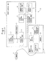
- Fig. 4 illustrates a conventional robot controller incorporating an image-processing function.
- the robot controller 20 includes a robot control unit 21 and an image-processing unit 22.
- the robot control unit 21 includes a robot control processor 23 for controlling the position/attitude of a robot, and which is not shown, a main memory 24 for storing the program and data, a servo control unit 27 for controlling a servo amplifier, which is not shown, upon receiving instructions from the processor 23, a communication control unit 28 for controlling the communication such as Ethernet (registered trademark) and Device net or communication with a teaching operator panel (not shown), a communication control unit 28, a peripheral equipment control unit 29 for controlling I/O, and a nonvolatile memory 30 for storing system programs and teach programs executed by the processor.
- a robot control unit 21 includes a robot control processor 23 for controlling the position/attitude of a robot, and which is not shown, a main memory 24 for storing the program and data, a servo control unit 27 for controlling a servo amplifier,
- the robot control processor 23 reads the operation program from the main memory 24, and writes, in the main memory 24, the data and addresses that are to be temporarily stored.
- the main memory 24 used by the processor 23 is connected to a first data bus 37 which is accessible at high speeds from the processor 23.
- An increase in the number of devices connected to the first data bus 37 results in an increase in the load on the bus, lowering the upper limit of operation frequency and depriving the bus of high-speed performance. Therefore, the main memory 24 only is connected to the first data bus 37.
- the devices 27, ---, 30 are connected to a second data bus 38.
- a processor control chip 25 is connected to both the first data bus 37 and the second data bus 38.
- Access to the second data bus 38 from the robot control processor 23 is controlled by the processor control chip 25.
- the amount of data flowing through the second data bus 38 is usually smaller than that through the first data bus 37. Therefore, performance is affected little even if the transfer rate through the second data bus 38 is lower than through the first data bus 37.
- many devices are connected to the second data bus 38.
- the constitution that is shown makes it possible to exchange the data among the devices 27, ---, 30 that are connected to the second data bus 38 without interrupting the operation of the first data bus 37. For example, it is possible to execute the processing of transmitting the input signals received from an external unit to the peripheral equipment control unit 29 by using the communication control unit 28 without interrupting the first data bus 37. Therefore, the data can be transferred without imposing a burden on the robot control processor 23.
- the transfer rate through the first data bus 37 and the second data bus 38 let it be assumed that the first data bus 37 has a bus width of 64 bits, a operating frequency of 100 MHz and the second data bus 38 has a bus width of 16 bits, and an operating frequency of 30 MHz. Then, the transfer rates through the first and second data buses 37 and 38 become 800 MBytes/sec and 60 MBytes/sec, creating a thirteen-fold difference in speed between the two buses. Also, when the processor 23 has a cache memory therein, the processing is executed while taking the data into the cache memory. Therefore, the processing speed is heightened more than the difference in the transfer rate.
- the image-processing unit 22 connected to the second data bus 38 has a camera interface unit 32 to which a camera 31 is connected, a memory 33 for storing image data detected by the camera 31, a processor 34 for processing image data upon accessing the memory 33 and for specifying the position of an object work, and a bus buffer 35 for isolating the bus in the image-processing unit from the second data bus 38.
- the image data of the object work are detected by a camera 31, are transferred to the memory 33 through the camera interface unit 32, are processed by the image-processing processor 34, and the results thereof are transferred to the robot control processor 23 through the second data bus 38. Therefore, the program teach points of the object work are corrected, enabling the robot hand to reliably grip the object work.
- the above conventional robot controller is disclosed in, for example, JP-A-2000-135689 .
- the image data picked up through the camera 31 are processed in the image-processing unit 22. Therefore, the image can be processed without imposing a burden on the robot control processor 23. Further, no image data flows through the data buses 37 and 38, and hence the operation for controlling the robot is not hindered by the transfer of image data.
- the robot control processor is used for controlling the robot and for processing images.
- a robot control processor 23A controls the robot and, at the same time, processes the images.
- the image data from a camera 31 are taken in through a camera interface unit 32, and are transferred to a main memory 24A through a second data bus 38 and a first data bus 37.
- the image data can be transferred even by using another processor connected to the second data bus 38 other than the robot control processor 23A or by using DMA (direct memory access).
- the main memory 24A is accessed by the robot control processor 23A at a high speed to process the image.
- the above conventional example requires neither the image-processing processor nor the image-processing memory, offering the advantage of lowering the cost of a robot controller 40.
- the image data picked up through the camera 31 are transferred up to the main memory 24A through the second data bus 38. Therefore, not only the data of the devices 27, ---, 30 but also the image data flow through the second data bus 38; i.e., the data of increased amounts flow through the second data bus 38, which may cause the occurrence of collision and traffic congestion on the second data bus 38, thus hindering to hinder the operation for controlling the robot.
- the image data picked up through the camera 31 are transferred up to the main memory 24A through the second data bus 38. Therefore, not only the data of the devices 27, ---, 30 but also the image data flow through the second data bus 38; i.e., the data of increased amounts flow through the second data bus 38, which may cause the occurrence of collision and traffic congestion on the second data bus 38, thus hindering to hinder the operation for controlling the robot.
- considered below is a case of transmitting 30 pieces of images per second, each image having 640 x 480 dots and being monochromatic data of 8 bits per dot.
- the amount of data per second is 9 MBytes/sec accounting for about 15% of the transfer ability of the bus if the second data bus 38 has a transfer rate of 60 MBytes/sec. Therefore, the effect on the data flowing through the second data bus 38 is no longer negligible, and it becomes highly probable that the transfer of data will be hindered.
- the above conventional example can be represented by a robot controller disclosed in, for example, JP-A-2001-191285 .
- the robot controller described in the above JP-A-2001-191285 not only the processor and the memory but also such devices as the servo control unit and the external equipment connection units are all connected to one bus. Therefore, the load on the bus increases, making it difficult to increase the transfer rate of the bus.
- large amounts of image data are transferred through the same bus as that of the robot control data, which hinders the transfer of data for controlling the robot.
- the conventional example (Fig. 4) is capable of processing images without imposing a burden on the robot control processor, but is provided with a processor for processing images separately from the robot control processor, raising the problem of increased cost of the robot controller as a whole.
- an image-processing function is incorporated in the robot controller at a lower cost than that of the constitution of Fig. 4, but the transfer of image data hinders the operation for controlling the robot.
- a robot controller having a function for controlling the motion of a robot, comprising:
- the environmental condition data are written by the writing unit into the memory through the first data bus, thereby avoiding a collision between the environmental condition data and the control data flowing through the second data bus and, hence, permitting the environmental condition data that are picked up to be transferred to the memory at a high speed without hindering the operation for controlling the robot.
- the above writing unit may be a processor control chip which is connected to the processor through the first data bus.
- the environmental condition data can be transferred to the memory by the processor control chip, which is the writing unit through the first data bus which is controlled. Therefore, the image data can be processed at a high speed.
- control data may at least include servo control data.
- the servo control data for controlling the joints of the robot upon receiving instructions from the processor are not affected by the environmental condition data. Therefore, the operation for controlling the joints of the robot is not hindered.
- control data may include peripheral equipment control data.
- the peripheral equipment control data for controlling the opening/closing of a robot hand are not affected by the environmental condition data. Therefore, the operation for controlling the opening/closing of the robot hand is not hindered.
- the environmental condition data may be image data picked up by the camera. According to this technological aspect, the image data having a large data capacity picked up by the camera can be transferred to the memory through the first data bus which features a speed higher than that of the second data bus. Therefore, the second data bus of a low speed is not occupied with processing the image data having a large data capacity, and the operation for controlling the robot is not hindered.
- the environmental condition data may be the data output from a force sensor.
- the output data picked up by the force sensor can be written into the memory at a high speed making it possible to process the control data based on the output data of the force sensor and to efficiently control the position/attitude of the robot.
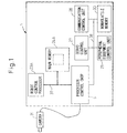
- Fig. 1 is a block diagram illustrating an embodiment of a robot controller according to the present invention.
- the robot controller 1 includes a robot control processor 23A, a main memory 24A directly accessible by the robot control processor 23A, a high-speed CPU external bus (first data bus) 37 connected to the main memory 24A, a second data bus 38 having a transfer rate lower than that of the CPU external bus 37 and used for transferring the control data for controlling the robot, and a processor control chip 5 connected to the robot control processor 23A through the CPU external bus 37.
- a CCD camera 31 is connected to the processor control chip 5 to detect or recognize the environmental conditions for the robot.
- the environmental conditions for the robot represent a relative positional relationship between the robot and an object work before and after being clamped.
- the CCD camera 31 in this embodiment is used for detecting the position of the object work before being clamped.
- the robot controller 1 is constituted in nearly the same manner as that of the prior art of Fig. 5, except that the CCD camera 31 is connected to the processor control chip 5.
- the constituent portions overlapping those of the prior art are denoted by the same reference numerals but are not described here again, and different portions only will be described.
- the robot control processor 23A has a function for controlling the position/attitude of a multi-joint robot, which is not shown, as well as a function for processing the image data of an object work picked up by the CCD camera 31 based on the control data flowing through the second data bus 38. That is, the robot control processor 23A of this embodiment is capable of executing the robot control and the image processing by using a single processor.
- the main memory 24A accessible by the robot control processor 23A at a high speed may be, for example, an SDRAM.
- the main memory 24A temporarily stores the operation program for operating the robot and the data, and, further, stores the image data (environmental condition data) detected by the CCD camera 31.
- the operation program and data that are stored, are read out upon being accessed by the robot control processor 23A. As the operation program and the like that are read out accumulate in the cache memory in the processor 23A, the image processing is executed at a higher speed.
- the high-speed CPU external bus 37 and the second data bus 38 are connected to the processor control chip 5.
- the CPU external bus 37 has a bus width of 64 bits and clocks of 100 MHz and the second data bus 38 has a bus width of 16 bits and clocks 30 MHz.
- the transfer rate of the CPU external bus 37 becomes 800 MBytes/sec and the transfer rate of the second data bus 38 becomes 60 MBytes/sec.
- the amount of data per second becomes 9 MBytes/sec.
- a ratio of the CPU external bus 37 occupied by the data can be compared to a ratio of the second data bus 38 occupied by the data to be that the ratio of the CPU external bus 37 occupied by the data is about 1%, while the ratio of the second data bus 38 occupied by the data is about 15%.
- the CPU external bus 37 transfers the data in a relatively small amount and affects the transfer of other data very little.
- the second data bus 38 transfers the data in relatively large amounts and may affect the transfer of other data. In the present invention, however, the image data picked up by the CCD camera 31 flow through the CPU external bus 37 of a wide bus width and are likely to affect the transfer of other data very little, and the operation for controlling the robot is not hindered.
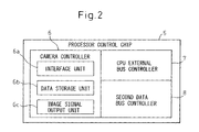
- the processor control chip 5 includes bus controllers such as a CPU external bus controller 7 and a second data bus controller 8, as well as a camera controller 6.
- the bus controllers 7 and 8 control the data flowing through the buses of different specifications.
- Devices connected to the second data bus 38 include, for example, servo control unit 27, communication control unit 28, peripheral equipment control unit 29, non-volatile memory 30 and the like (Fig. 1).
- the servo control unit 27 receives an instruction from the robot control processor 23A, sends an instruction to a servo amplifier, which is not shown, and controls a current flowing into servo motors for moving the joints of the robot.
- the communication control unit 28 controls the network communication such as Ethernet (registered trademark) and a Device net, and controls the communication to a teaching operation panel, which is not shown.
- the peripheral equipment control unit 29 controls ON/OFF of the lamp and the open/close signals of the robot hand.
- the non-volatile memory 30 stores the data which are not erased even when the power source of the robot is turned off, and stores system programs and teach programs executed by, for example, the processor.
- the teaching operation panel includes a key input device for inputting teach data through the key operation, a display unit for displaying various data of the robot and a CPU for controlling them.
- the camera controller 6 receives the image data from the CCD camera which is a vision sensor, send the image data that are received to the CPU external bus controller 7, and transfers the image data to the main memory 24A, and is equipped with an interface unit 6a and a data storage unit 6b.
- the interface unit 6a has a function for converting the image data received from the camera 31 into a form that is handled by the processor 23A.
- the interface unit 6a works as an interface circuit including an analog/digital converter.
- the interface unit 6a serves as a receiver circuit.
- a camera that uses such an interface as USB, IEEE 1394 or Ethernet (registered trademark) transfers the digital data.
- the interface unit works as a receiver circuit for the respective communications.
- the data storage unit 6b works to temporarily store the data until the data transfer timing is taken, and comprises, for example, an FIFO buffer.
- an image display unit which is not shown.
- the image signal output unit 6c outputs an image signal to the image display unit, which is not shown. Further, a dedicated image display unit is often omitted by displaying an image for adjustment on the teaching operator panel, which is not shown.
- the CCD camera 31 is attached to, for example, an end of the robot hand, which is not shown, to measure a particular position of the object work that serves as a teach point of the operation program. For example, if the machining system using the robot is to deburr the object work, the particular position to be measured is a portion forming burr along the ridges of the object work.
- the CCD camera 31 there can be arbitrarily used a three-dimensional camera or a two-dimensional camera. When the three-dimensional camera is used, the position forming the burr is photographed based on the principle of a trigonometrical survey.
- the image data that are taken in are processed by the processor 23A to calculate the burring position of the object work.
- the robot having such an image-processing function has been put into practice as an intelligent robot.
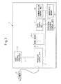
- Fig. 3 illustrates a modified example of the robot controller 1 of Fig. 1.
- This modified example is different from the above embodiment with respect that the main memory 24A is connected to the processor control chip 5 through a memory bus 39.
- the image data picked up by the CCD camera 31 are transferred to the main memory 24A at high speeds without hindering the transfer of data through the second data bus.
- the constitution in other respects is the same as that of the above embodiment and is not described here again.
- the image data picked up by the CCD camera 31 are transferred to the main memory 24A at a high speed through the high-speed CPU external bus 37 or the memory bus 39, preventing the transfer of robot control signals from being hindered by the image data. Therefore, it is possible to realize an intelligent robot controller for processing data from various sensors at a decreased cost without decreasing the performance of the robot controller.
- a force sensor may be used in place of the CCD camera 31 of this embodiment.
- the force sensor there is used, for example, a six-axis force sensor having a distortion gauge and incorporating a plurality of bridge circuits driven by AC power from an oscillator.
- the force sensor is provided between an end of the arm or the arm and the hand of the robot body, making it possible to assemble the object work in a flexible motion.
- the CCD camera 31 is directly connected to the processor control chip 5. It is, however, also allowable to connect the CCD camera 31 to the processor control chip through a camera interface unit which is provided separately from the processor control chip, without imposing any limitation on the connection between the CCD camera 31 and the processor control chip 5.
Landscapes
- Engineering & Computer Science (AREA)
- Automation & Control Theory (AREA)
- Physics & Mathematics (AREA)
- Mathematical Physics (AREA)
- Evolutionary Computation (AREA)
- Fuzzy Systems (AREA)
- Artificial Intelligence (AREA)
- Software Systems (AREA)
- Robotics (AREA)
- Mechanical Engineering (AREA)
- General Physics & Mathematics (AREA)
- Numerical Control (AREA)
- Manipulator (AREA)
Abstract
Description
- The present invention relates to a robot controller having a function for controlling the motion of a robot by processing data picked up by detection means such as a camera or a force sensor that detects the environmental conditions for the robot.
- There has heretofore been known a robot controller incorporating an image-processing function as the robot controller having a function for correcting the motion of the robot that is taught by processing environmental condition data that represents the environmental conditions for the robot.
- Fig. 4 illustrates a conventional robot controller incorporating an image-processing function. The
robot controller 20 includes arobot control unit 21 and an image-processing unit 22. Therobot control unit 21 includes arobot control processor 23 for controlling the position/attitude of a robot, and which is not shown, amain memory 24 for storing the program and data, aservo control unit 27 for controlling a servo amplifier, which is not shown, upon receiving instructions from theprocessor 23, acommunication control unit 28 for controlling the communication such as Ethernet (registered trademark) and Device net or communication with a teaching operator panel (not shown), acommunication control unit 28, a peripheralequipment control unit 29 for controlling I/O, and anonvolatile memory 30 for storing system programs and teach programs executed by the processor. - The
robot control processor 23 reads the operation program from themain memory 24, and writes, in themain memory 24, the data and addresses that are to be temporarily stored. To increase the processing speed of theprocessor 23, themain memory 24 used by theprocessor 23 is connected to afirst data bus 37 which is accessible at high speeds from theprocessor 23. An increase in the number of devices connected to thefirst data bus 37 results in an increase in the load on the bus, lowering the upper limit of operation frequency and depriving the bus of high-speed performance. Therefore, themain memory 24 only is connected to thefirst data bus 37. Thedevices 27, ---, 30 are connected to asecond data bus 38. Aprocessor control chip 25 is connected to both thefirst data bus 37 and thesecond data bus 38. - Access to the
second data bus 38 from therobot control processor 23 is controlled by theprocessor control chip 25. The amount of data flowing through thesecond data bus 38 is usually smaller than that through thefirst data bus 37. Therefore, performance is affected little even if the transfer rate through thesecond data bus 38 is lower than through thefirst data bus 37. Thus, many devices are connected to thesecond data bus 38. Further, the constitution that is shown makes it possible to exchange the data among thedevices 27, ---, 30 that are connected to thesecond data bus 38 without interrupting the operation of thefirst data bus 37. For example, it is possible to execute the processing of transmitting the input signals received from an external unit to the peripheralequipment control unit 29 by using thecommunication control unit 28 without interrupting thefirst data bus 37. Therefore, the data can be transferred without imposing a burden on therobot control processor 23. - As for the transfer rate through the
first data bus 37 and thesecond data bus 38, let it be assumed that thefirst data bus 37 has a bus width of 64 bits, a operating frequency of 100 MHz and thesecond data bus 38 has a bus width of 16 bits, and an operating frequency of 30 MHz. Then, the transfer rates through the first andsecond data buses processor 23 has a cache memory therein, the processing is executed while taking the data into the cache memory. Therefore, the processing speed is heightened more than the difference in the transfer rate. - The image-
processing unit 22 connected to thesecond data bus 38 has acamera interface unit 32 to which acamera 31 is connected, amemory 33 for storing image data detected by thecamera 31, aprocessor 34 for processing image data upon accessing thememory 33 and for specifying the position of an object work, and a bus buffer 35 for isolating the bus in the image-processing unit from thesecond data bus 38. - The image data of the object work are detected by a
camera 31, are transferred to thememory 33 through thecamera interface unit 32, are processed by the image-processing processor 34, and the results thereof are transferred to therobot control processor 23 through thesecond data bus 38. Therefore, the program teach points of the object work are corrected, enabling the robot hand to reliably grip the object work. The above conventional robot controller is disclosed in, for example,JP-A-2000-135689 - In the case of the above constitution, the image data picked up through the
camera 31 are processed in the image-processing unit 22. Therefore, the image can be processed without imposing a burden on therobot control processor 23. Further, no image data flows through thedata buses - However, provision of the
robot controller 20 with the image-processing unit 22 separately from therobot control unit 21 is accompanied by the problem of an increase in the cost of therobot controller 20. - Next, according to another conventional robot controller, the robot control processor is used for controlling the robot and for processing images. In this conventional example as shown in Fig. 5, a
robot control processor 23A controls the robot and, at the same time, processes the images. The image data from acamera 31 are taken in through acamera interface unit 32, and are transferred to amain memory 24A through asecond data bus 38 and afirst data bus 37. The image data can be transferred even by using another processor connected to thesecond data bus 38 other than therobot control processor 23A or by using DMA (direct memory access). Themain memory 24A is accessed by therobot control processor 23A at a high speed to process the image. - The above conventional example requires neither the image-processing processor nor the image-processing memory, offering the advantage of lowering the cost of a
robot controller 40. - However, the image data picked up through the
camera 31 are transferred up to themain memory 24A through thesecond data bus 38. Therefore, not only the data of thedevices 27, ---, 30 but also the image data flow through thesecond data bus 38; i.e., the data of increased amounts flow through thesecond data bus 38, which may cause the occurrence of collision and traffic congestion on thesecond data bus 38, thus hindering to hinder the operation for controlling the robot. For example, considered below is a case of transmitting 30 pieces of images per second, each image having 640 x 480 dots and being monochromatic data of 8 bits per dot. In this case, the amount of data per second is 9 MBytes/sec accounting for about 15% of the transfer ability of the bus if thesecond data bus 38 has a transfer rate of 60 MBytes/sec. Therefore, the effect on the data flowing through thesecond data bus 38 is no longer negligible, and it becomes highly probable that the transfer of data will be hindered. The above conventional example can be represented by a robot controller disclosed in, for example,JP-A-2001-191285 JP-A-2001-191285 - As described above, the conventional example (Fig. 4) is capable of processing images without imposing a burden on the robot control processor, but is provided with a processor for processing images separately from the robot control processor, raising the problem of increased cost of the robot controller as a whole.
- According to another conventional example (Fig. 5), an image-processing function is incorporated in the robot controller at a lower cost than that of the constitution of Fig. 4, but the transfer of image data hinders the operation for controlling the robot.
- It is an object of the present invention to provide a robot controller capable of transferring the environmental condition data picked up by detection means to a memory at high speeds without hindering the operation for controlling the robot.
- To achieve the above object according to the present invention, there is provided a robot controller having a function for controlling the motion of a robot, comprising:
- a processor for controlling the robot and for processing the environmental condition data representing the environmental conditions for the robot;
- a memory accessible by the processor;
- a writing unit for executing a function of writing the environmental condition into the memory;
- a first data bus connected to the memory; and
- a second data bus having a transfer rate lower than that of the first data bus and for transferring the control data used for controlling the robot;
- wherein the writing unit writes the environmental condition data into the memory through the first data bus, not through the second data bus.
- According to the present invention, the environmental condition data are written by the writing unit into the memory through the first data bus, thereby avoiding a collision between the environmental condition data and the control data flowing through the second data bus and, hence, permitting the environmental condition data that are picked up to be transferred to the memory at a high speed without hindering the operation for controlling the robot.
- Here, the above writing unit may be a processor control chip which is connected to the processor through the first data bus.
- According to this technological aspect, the environmental condition data can be transferred to the memory by the processor control chip, which is the writing unit through the first data bus which is controlled. Therefore, the image data can be processed at a high speed.
- Further, the control data may at least include servo control data. According to this technological aspect, the servo control data for controlling the joints of the robot upon receiving instructions from the processor are not affected by the environmental condition data. Therefore, the operation for controlling the joints of the robot is not hindered.
- Further, the control data may include peripheral equipment control data. According to this technological aspect, the peripheral equipment control data for controlling the opening/closing of a robot hand are not affected by the environmental condition data. Therefore, the operation for controlling the opening/closing of the robot hand is not hindered. Further, the environmental condition data may be image data picked up by the camera. According to this technological aspect, the image data having a large data capacity picked up by the camera can be transferred to the memory through the first data bus which features a speed higher than that of the second data bus. Therefore, the second data bus of a low speed is not occupied with processing the image data having a large data capacity, and the operation for controlling the robot is not hindered.
- Further, the environmental condition data may be the data output from a force sensor. According to this technological aspect, the output data picked up by the force sensor can be written into the memory at a high speed making it possible to process the control data based on the output data of the force sensor and to efficiently control the position/attitude of the robot.
- The above and other objects, features and advantages of the invention will become more obvious from the description of the following preferred embodiment in conjunction with the accompanying drawings in which:
- Fig. 1 is a block diagram illustrating an embodiment of a robot controller according to the present invention;
- Fig. 2 is a diagram illustrating a processor control chip of Fig. 1 in detail;
- Fig. 3 is a block diagram illustrating a modified example of the robot controller shown in Fig. 1;
- Fig. 4 is a block diagram illustrating a conventional robot controller; and
- Fig. 5 is a block diagram illustrating another conventional robot controller.
- Fig. 1 is a block diagram illustrating an embodiment of a robot controller according to the present invention. The
robot controller 1 includes arobot control processor 23A, amain memory 24A directly accessible by therobot control processor 23A, a high-speed CPU external bus (first data bus) 37 connected to themain memory 24A, asecond data bus 38 having a transfer rate lower than that of the CPUexternal bus 37 and used for transferring the control data for controlling the robot, and aprocessor control chip 5 connected to therobot control processor 23A through the CPUexternal bus 37. ACCD camera 31 is connected to theprocessor control chip 5 to detect or recognize the environmental conditions for the robot. The environmental conditions for the robot represent a relative positional relationship between the robot and an object work before and after being clamped. TheCCD camera 31 in this embodiment is used for detecting the position of the object work before being clamped. - The
robot controller 1 is constituted in nearly the same manner as that of the prior art of Fig. 5, except that theCCD camera 31 is connected to theprocessor control chip 5. Hereinafter, the constituent portions overlapping those of the prior art are denoted by the same reference numerals but are not described here again, and different portions only will be described. - The
robot control processor 23A has a function for controlling the position/attitude of a multi-joint robot, which is not shown, as well as a function for processing the image data of an object work picked up by theCCD camera 31 based on the control data flowing through thesecond data bus 38. That is, therobot control processor 23A of this embodiment is capable of executing the robot control and the image processing by using a single processor. - The
main memory 24A accessible by therobot control processor 23A at a high speed may be, for example, an SDRAM. Themain memory 24A temporarily stores the operation program for operating the robot and the data, and, further, stores the image data (environmental condition data) detected by theCCD camera 31. The operation program and data that are stored, are read out upon being accessed by therobot control processor 23A. As the operation program and the like that are read out accumulate in the cache memory in theprocessor 23A, the image processing is executed at a higher speed. - The high-speed CPU
external bus 37 and thesecond data bus 38 are connected to theprocessor control chip 5. For example, let it be assumed that the CPUexternal bus 37 has a bus width of 64 bits and clocks of 100 MHz and thesecond data bus 38 has a bus width of 16 bits andclocks 30 MHz. In this case, the transfer rate of the CPUexternal bus 37 becomes 800 MBytes/sec and the transfer rate of thesecond data bus 38 becomes 60 MBytes/sec. When an image of 640 x480 dots is to be transferred at a rate of 30 pieces per second with monochromatic data of 8 bits per dot, the amount of data per second becomes 9 MBytes/sec. - In transferring the data at a transfer rate of 9 MBytes/sec, a ratio of the CPU
external bus 37 occupied by the data can be compared to a ratio of thesecond data bus 38 occupied by the data to be that the ratio of the CPUexternal bus 37 occupied by the data is about 1%, while the ratio of thesecond data bus 38 occupied by the data is about 15%. The CPUexternal bus 37 transfers the data in a relatively small amount and affects the transfer of other data very little. Thesecond data bus 38, on the other hand, transfers the data in relatively large amounts and may affect the transfer of other data. In the present invention, however, the image data picked up by theCCD camera 31 flow through the CPUexternal bus 37 of a wide bus width and are likely to affect the transfer of other data very little, and the operation for controlling the robot is not hindered. - Referring to Fig. 2, the
processor control chip 5 includes bus controllers such as a CPUexternal bus controller 7 and a seconddata bus controller 8, as well as acamera controller 6. Thebus controllers - Devices connected to the
second data bus 38 include, for example,servo control unit 27,communication control unit 28, peripheralequipment control unit 29,non-volatile memory 30 and the like (Fig. 1). - The
servo control unit 27 receives an instruction from therobot control processor 23A, sends an instruction to a servo amplifier, which is not shown, and controls a current flowing into servo motors for moving the joints of the robot. Thecommunication control unit 28 controls the network communication such as Ethernet (registered trademark) and a Device net, and controls the communication to a teaching operation panel, which is not shown. The peripheralequipment control unit 29 controls ON/OFF of the lamp and the open/close signals of the robot hand. Thenon-volatile memory 30 stores the data which are not erased even when the power source of the robot is turned off, and stores system programs and teach programs executed by, for example, the processor. The teaching operation panel includes a key input device for inputting teach data through the key operation, a display unit for displaying various data of the robot and a CPU for controlling them. - Referring to Fig. 2, the
camera controller 6 receives the image data from the CCD camera which is a vision sensor, send the image data that are received to the CPUexternal bus controller 7, and transfers the image data to themain memory 24A, and is equipped with aninterface unit 6a and a data storage unit 6b. Theinterface unit 6a has a function for converting the image data received from thecamera 31 into a form that is handled by theprocessor 23A. In the case of analog data, theinterface unit 6a works as an interface circuit including an analog/digital converter. In the case of digital data, on the other hand, theinterface unit 6a serves as a receiver circuit. For example, a camera that uses such an interface as USB, IEEE 1394 or Ethernet (registered trademark) transfers the digital data. Therefore, the interface unit works as a receiver circuit for the respective communications. The data storage unit 6b works to temporarily store the data until the data transfer timing is taken, and comprises, for example, an FIFO buffer. In order to display the image taken by thecamera 31 and to adjust the direction and focus of the camera, there is often provided an image display unit, which is not shown. The imagesignal output unit 6c outputs an image signal to the image display unit, which is not shown. Further, a dedicated image display unit is often omitted by displaying an image for adjustment on the teaching operator panel, which is not shown. - The
CCD camera 31 is attached to, for example, an end of the robot hand, which is not shown, to measure a particular position of the object work that serves as a teach point of the operation program. For example, if the machining system using the robot is to deburr the object work, the particular position to be measured is a portion forming burr along the ridges of the object work. As theCCD camera 31, there can be arbitrarily used a three-dimensional camera or a two-dimensional camera. When the three-dimensional camera is used, the position forming the burr is photographed based on the principle of a trigonometrical survey. The image data that are taken in are processed by theprocessor 23A to calculate the burring position of the object work. The robot having such an image-processing function has been put into practice as an intelligent robot. - Fig. 3 illustrates a modified example of the
robot controller 1 of Fig. 1. This modified example is different from the above embodiment with respect that themain memory 24A is connected to theprocessor control chip 5 through amemory bus 39. In this constitution, too, the image data picked up by theCCD camera 31 are transferred to themain memory 24A at high speeds without hindering the transfer of data through the second data bus. The constitution in other respects is the same as that of the above embodiment and is not described here again. - According to this embodiment as described above, the image data picked up by the
CCD camera 31 are transferred to themain memory 24A at a high speed through the high-speed CPUexternal bus 37 or thememory bus 39, preventing the transfer of robot control signals from being hindered by the image data. Therefore, it is possible to realize an intelligent robot controller for processing data from various sensors at a decreased cost without decreasing the performance of the robot controller. - The present invention is not limited to the above embodiment only, but can be put into practice by being modified in a variety of ways without departing from the spirit and scope of the invention. For example, a force sensor may be used in place of the
CCD camera 31 of this embodiment. As the force sensor, there is used, for example, a six-axis force sensor having a distortion gauge and incorporating a plurality of bridge circuits driven by AC power from an oscillator. The force sensor is provided between an end of the arm or the arm and the hand of the robot body, making it possible to assemble the object work in a flexible motion. - In this embodiment, further, the
CCD camera 31 is directly connected to theprocessor control chip 5. It is, however, also allowable to connect theCCD camera 31 to the processor control chip through a camera interface unit which is provided separately from the processor control chip, without imposing any limitation on the connection between theCCD camera 31 and theprocessor control chip 5. - Though the invention was described above in connection with a preferred embodiment, people skilled in the art will easily understand that a variety of modifications and changes can be made without departing from the scope of claims described below.
Claims (6)
- A robot controller comprising:a processor (23A) for controlling the robot and for processing the environmental condition data representing the environmental conditions for said robot;a memory (24A) accessible by said processor (23A);a writing unit for executing a function of writing said environmental condition into said memory (24A);a first data bus (37) connected to said memory (24A); anda second data bus (38) having a transfer rate lower than that of said first data bus (37) and for transferring the control data used for controlling said robot;characterized in that said writing unit writes said environmental condition data into said memory (24A) through said first data bus (37), not through said second data bus (38).
- A robot controller (1) according to claim 1, wherein said writing unit is a processor control chip (5) which is connected to said processor (23A) through said first data bus (37).
- A robot controller (1) according to claim 1 or 2, wherein said control data include servo control data.
- A robot controller (1) according to claim 1 or 2, wherein said control data include peripheral equipment control data.
- A robot controller (1) according to claim 1 or 2, wherein said environmental condition data are image data picked up by a camera (31).
- A robot controller (1) according to claim 1 or 2, wherein said environmental condition data are the data output from a force sensor.
Applications Claiming Priority (1)
| Application Number | Priority Date | Filing Date | Title |
|---|---|---|---|
| JP2005171052A JP2006344136A (en) | 2005-06-10 | 2005-06-10 | Robot controller |
Publications (2)
| Publication Number | Publication Date |
|---|---|
| EP1734425A2 true EP1734425A2 (en) | 2006-12-20 |
| EP1734425A3 EP1734425A3 (en) | 2007-03-07 |
Family
ID=36999780
Family Applications (1)
| Application Number | Title | Priority Date | Filing Date |
|---|---|---|---|
| EP06011663A Withdrawn EP1734425A3 (en) | 2005-06-10 | 2006-06-06 | Robot controller |
Country Status (4)
| Country | Link |
|---|---|
| US (1) | US20060279246A1 (en) |
| EP (1) | EP1734425A3 (en) |
| JP (1) | JP2006344136A (en) |
| CN (1) | CN1876332A (en) |
Cited By (24)
| Publication number | Priority date | Publication date | Assignee | Title |
|---|---|---|---|---|
| WO2011090895A1 (en) * | 2010-01-20 | 2011-07-28 | Faro Technologies, Inc. | Portable articulated arm coordinate measuring machine with multi-bus arm technology |
| US8171650B2 (en) | 2010-01-20 | 2012-05-08 | Faro Technologies, Inc. | Intelligent repeatable arm mounting system |
| US8284407B2 (en) | 2010-01-20 | 2012-10-09 | Faro Technologies, Inc. | Coordinate measuring machine having an illuminated probe end and method of operation |
| US8630314B2 (en) | 2010-01-11 | 2014-01-14 | Faro Technologies, Inc. | Method and apparatus for synchronizing measurements taken by multiple metrology devices |
| WO2014014692A1 (en) * | 2012-07-17 | 2014-01-23 | Faro Technologies, Inc. | Portable articulated arm coordinate measuring machine with optical communications bus |
| US8638446B2 (en) | 2010-01-20 | 2014-01-28 | Faro Technologies, Inc. | Laser scanner or laser tracker having a projector |
| US8677643B2 (en) | 2010-01-20 | 2014-03-25 | Faro Technologies, Inc. | Coordinate measurement machines with removable accessories |
| US8832954B2 (en) | 2010-01-20 | 2014-09-16 | Faro Technologies, Inc. | Coordinate measurement machines with removable accessories |
| US8875409B2 (en) | 2010-01-20 | 2014-11-04 | Faro Technologies, Inc. | Coordinate measurement machines with removable accessories |
| US8898919B2 (en) | 2010-01-20 | 2014-12-02 | Faro Technologies, Inc. | Coordinate measurement machine with distance meter used to establish frame of reference |
| US9113023B2 (en) | 2009-11-20 | 2015-08-18 | Faro Technologies, Inc. | Three-dimensional scanner with spectroscopic energy detector |
| US9168654B2 (en) | 2010-11-16 | 2015-10-27 | Faro Technologies, Inc. | Coordinate measuring machines with dual layer arm |
| US9210288B2 (en) | 2009-11-20 | 2015-12-08 | Faro Technologies, Inc. | Three-dimensional scanner with dichroic beam splitters to capture a variety of signals |
| USRE45854E1 (en) | 2006-07-03 | 2016-01-19 | Faro Technologies, Inc. | Method and an apparatus for capturing three-dimensional data of an area of space |
| US9329271B2 (en) | 2010-05-10 | 2016-05-03 | Faro Technologies, Inc. | Method for optically scanning and measuring an environment |
| US9372265B2 (en) | 2012-10-05 | 2016-06-21 | Faro Technologies, Inc. | Intermediate two-dimensional scanning with a three-dimensional scanner to speed registration |
| US9417056B2 (en) | 2012-01-25 | 2016-08-16 | Faro Technologies, Inc. | Device for optically scanning and measuring an environment |
| US9513107B2 (en) | 2012-10-05 | 2016-12-06 | Faro Technologies, Inc. | Registration calculation between three-dimensional (3D) scans based on two-dimensional (2D) scan data from a 3D scanner |
| US9529083B2 (en) | 2009-11-20 | 2016-12-27 | Faro Technologies, Inc. | Three-dimensional scanner with enhanced spectroscopic energy detector |
| US9628775B2 (en) | 2010-01-20 | 2017-04-18 | Faro Technologies, Inc. | Articulated arm coordinate measurement machine having a 2D camera and method of obtaining 3D representations |
| US10060722B2 (en) | 2010-01-20 | 2018-08-28 | Faro Technologies, Inc. | Articulated arm coordinate measurement machine having a 2D camera and method of obtaining 3D representations |
| US10067231B2 (en) | 2012-10-05 | 2018-09-04 | Faro Technologies, Inc. | Registration calculation of three-dimensional scanner data performed between scans based on measurements by two-dimensional scanner |
| US10175037B2 (en) | 2015-12-27 | 2019-01-08 | Faro Technologies, Inc. | 3-D measuring device with battery pack |
| US10281259B2 (en) | 2010-01-20 | 2019-05-07 | Faro Technologies, Inc. | Articulated arm coordinate measurement machine that uses a 2D camera to determine 3D coordinates of smoothly continuous edge features |
Families Citing this family (25)
| Publication number | Priority date | Publication date | Assignee | Title |
|---|---|---|---|---|
| WO2012141810A1 (en) | 2011-03-03 | 2012-10-18 | Faro Technologies, Inc. | Target apparatus and method |
| US9482755B2 (en) | 2008-11-17 | 2016-11-01 | Faro Technologies, Inc. | Measurement system having air temperature compensation between a target and a laser tracker |
| US9551575B2 (en) | 2009-03-25 | 2017-01-24 | Faro Technologies, Inc. | Laser scanner having a multi-color light source and real-time color receiver |
| DE102009015920B4 (en) | 2009-03-25 | 2014-11-20 | Faro Technologies, Inc. | Device for optically scanning and measuring an environment |
| JP4699572B2 (en) * | 2009-09-28 | 2011-06-15 | パナソニック株式会社 | Robot arm control apparatus and control method, robot, robot arm control program, and integrated electronic circuit for robot arm control |
| DE102009057101A1 (en) | 2009-11-20 | 2011-05-26 | Faro Technologies, Inc., Lake Mary | Device for optically scanning and measuring an environment |
| US9163922B2 (en) | 2010-01-20 | 2015-10-20 | Faro Technologies, Inc. | Coordinate measurement machine with distance meter and camera to determine dimensions within camera images |
| US8615893B2 (en) | 2010-01-20 | 2013-12-31 | Faro Technologies, Inc. | Portable articulated arm coordinate measuring machine having integrated software controls |
| US9377885B2 (en) | 2010-04-21 | 2016-06-28 | Faro Technologies, Inc. | Method and apparatus for locking onto a retroreflector with a laser tracker |
| US9772394B2 (en) | 2010-04-21 | 2017-09-26 | Faro Technologies, Inc. | Method and apparatus for following an operator and locking onto a retroreflector with a laser tracker |
| US8619265B2 (en) | 2011-03-14 | 2013-12-31 | Faro Technologies, Inc. | Automatic measurement of dimensional data with a laser tracker |
| US9400170B2 (en) | 2010-04-21 | 2016-07-26 | Faro Technologies, Inc. | Automatic measurement of dimensional data within an acceptance region by a laser tracker |
| US9164173B2 (en) | 2011-04-15 | 2015-10-20 | Faro Technologies, Inc. | Laser tracker that uses a fiber-optic coupler and an achromatic launch to align and collimate two wavelengths of light |
| US9686532B2 (en) | 2011-04-15 | 2017-06-20 | Faro Technologies, Inc. | System and method of acquiring three-dimensional coordinates using multiple coordinate measurement devices |
| US9482529B2 (en) | 2011-04-15 | 2016-11-01 | Faro Technologies, Inc. | Three-dimensional coordinate scanner and method of operation |
| US8537376B2 (en) | 2011-04-15 | 2013-09-17 | Faro Technologies, Inc. | Enhanced position detector in laser tracker |
| JP5895420B2 (en) | 2011-09-21 | 2016-03-30 | セイコーエプソン株式会社 | Robot control device and robot system |
| JP6099675B2 (en) | 2012-01-27 | 2017-03-22 | ファロ テクノロジーズ インコーポレーテッド | Inspection method by barcode identification |
| US9041914B2 (en) | 2013-03-15 | 2015-05-26 | Faro Technologies, Inc. | Three-dimensional coordinate scanner and method of operation |
| US9769930B2 (en) | 2013-03-19 | 2017-09-19 | Muth Mirror Systems, Llc | Module placement device and method |
| RU2578759C2 (en) | 2013-09-06 | 2016-03-27 | Общество С Ограниченной Ответственностью "Кибернетические Технологии" | Control device in cyber-physical systems, primarily for controlling mobile robots and/or unmanned aerial vehicles |
| US9395174B2 (en) | 2014-06-27 | 2016-07-19 | Faro Technologies, Inc. | Determining retroreflector orientation by optimizing spatial fit |
| CN109887396A (en) * | 2017-12-06 | 2019-06-14 | 北京猎户星空科技有限公司 | A kind of robot teaching system, method and device |
| CN109947095A (en) * | 2019-02-14 | 2019-06-28 | 广东赛斐迩物流科技有限公司 | A kind of warehouse transfer robot |
| EP4095628A1 (en) * | 2021-05-25 | 2022-11-30 | Siemens Aktiengesellschaft | Method and system for controlling a machine by executing program steps which verifiably execute predefined control tasks |
Family Cites Families (9)
| Publication number | Priority date | Publication date | Assignee | Title |
|---|---|---|---|---|
| JPS61117605A (en) * | 1984-11-14 | 1986-06-05 | Hitachi Ltd | Robot control method |
| JPS62232006A (en) * | 1986-04-02 | 1987-10-12 | Yokogawa Electric Corp | Robot system |
| US5369748A (en) * | 1991-08-23 | 1994-11-29 | Nexgen Microsystems | Bus arbitration in a dual-bus architecture where one bus has relatively high latency |
| JPH1133960A (en) * | 1997-07-17 | 1999-02-09 | Fanuc Ltd | Method for controlling robot |
| AU2001243537A1 (en) * | 2000-03-10 | 2001-09-24 | Meta Controls, Inc. | Smart camera |
| JP2002154081A (en) * | 2000-11-16 | 2002-05-28 | Nec Access Technica Ltd | Robot, its facial expression method and detecting method for step difference and lifting-up state |
| DE10129188A1 (en) * | 2001-06-19 | 2003-02-06 | Dm Technologies Gmbh & Co | Multimedia machine control |
| US7327396B2 (en) * | 2002-04-10 | 2008-02-05 | National Instruments Corporation | Smart camera with a plurality of slots for modular expansion capability through a variety of function modules connected to the smart camera |
| AT413391B (en) * | 2003-03-27 | 2006-02-15 | Andritz Ag Maschf | SORTER FOR CLEANING A FIBER SUSPENSION |
-
2005
- 2005-06-10 JP JP2005171052A patent/JP2006344136A/en active Pending
-
2006
- 2006-06-06 EP EP06011663A patent/EP1734425A3/en not_active Withdrawn
- 2006-06-07 CN CNA2006100879194A patent/CN1876332A/en active Pending
- 2006-06-07 US US11/448,010 patent/US20060279246A1/en not_active Abandoned
Cited By (43)
| Publication number | Priority date | Publication date | Assignee | Title |
|---|---|---|---|---|
| USRE45854E1 (en) | 2006-07-03 | 2016-01-19 | Faro Technologies, Inc. | Method and an apparatus for capturing three-dimensional data of an area of space |
| US9529083B2 (en) | 2009-11-20 | 2016-12-27 | Faro Technologies, Inc. | Three-dimensional scanner with enhanced spectroscopic energy detector |
| US9210288B2 (en) | 2009-11-20 | 2015-12-08 | Faro Technologies, Inc. | Three-dimensional scanner with dichroic beam splitters to capture a variety of signals |
| US9113023B2 (en) | 2009-11-20 | 2015-08-18 | Faro Technologies, Inc. | Three-dimensional scanner with spectroscopic energy detector |
| US8630314B2 (en) | 2010-01-11 | 2014-01-14 | Faro Technologies, Inc. | Method and apparatus for synchronizing measurements taken by multiple metrology devices |
| US9628775B2 (en) | 2010-01-20 | 2017-04-18 | Faro Technologies, Inc. | Articulated arm coordinate measurement machine having a 2D camera and method of obtaining 3D representations |
| US8537374B2 (en) | 2010-01-20 | 2013-09-17 | Faro Technologies, Inc. | Coordinate measuring machine having an illuminated probe end and method of operation |
| US8601702B2 (en) | 2010-01-20 | 2013-12-10 | Faro Technologies, Inc. | Display for coordinate measuring machine |
| US8533967B2 (en) | 2010-01-20 | 2013-09-17 | Faro Technologies, Inc. | Coordinate measurement machines with removable accessories |
| WO2011090895A1 (en) * | 2010-01-20 | 2011-07-28 | Faro Technologies, Inc. | Portable articulated arm coordinate measuring machine with multi-bus arm technology |
| US8638446B2 (en) | 2010-01-20 | 2014-01-28 | Faro Technologies, Inc. | Laser scanner or laser tracker having a projector |
| US8677643B2 (en) | 2010-01-20 | 2014-03-25 | Faro Technologies, Inc. | Coordinate measurement machines with removable accessories |
| US8763266B2 (en) | 2010-01-20 | 2014-07-01 | Faro Technologies, Inc. | Coordinate measurement device |
| US8832954B2 (en) | 2010-01-20 | 2014-09-16 | Faro Technologies, Inc. | Coordinate measurement machines with removable accessories |
| US8875409B2 (en) | 2010-01-20 | 2014-11-04 | Faro Technologies, Inc. | Coordinate measurement machines with removable accessories |
| US8898919B2 (en) | 2010-01-20 | 2014-12-02 | Faro Technologies, Inc. | Coordinate measurement machine with distance meter used to establish frame of reference |
| US8942940B2 (en) | 2010-01-20 | 2015-01-27 | Faro Technologies, Inc. | Portable articulated arm coordinate measuring machine and integrated electronic data processing system |
| US10060722B2 (en) | 2010-01-20 | 2018-08-28 | Faro Technologies, Inc. | Articulated arm coordinate measurement machine having a 2D camera and method of obtaining 3D representations |
| US8171650B2 (en) | 2010-01-20 | 2012-05-08 | Faro Technologies, Inc. | Intelligent repeatable arm mounting system |
| GB2490631A (en) * | 2010-01-20 | 2012-11-07 | Faro Tech Inc | Portable articulated arm coordinated measuring machine with multi-bus arm technology |
| US10281259B2 (en) | 2010-01-20 | 2019-05-07 | Faro Technologies, Inc. | Articulated arm coordinate measurement machine that uses a 2D camera to determine 3D coordinates of smoothly continuous edge features |
| US8284407B2 (en) | 2010-01-20 | 2012-10-09 | Faro Technologies, Inc. | Coordinate measuring machine having an illuminated probe end and method of operation |
| US8276286B2 (en) | 2010-01-20 | 2012-10-02 | Faro Technologies, Inc. | Display for coordinate measuring machine |
| GB2490631B (en) * | 2010-01-20 | 2016-11-02 | Faro Tech Inc | Portable articulated arm coordinate measuring machine with multi-bus arm technology |
| US9684078B2 (en) | 2010-05-10 | 2017-06-20 | Faro Technologies, Inc. | Method for optically scanning and measuring an environment |
| US9329271B2 (en) | 2010-05-10 | 2016-05-03 | Faro Technologies, Inc. | Method for optically scanning and measuring an environment |
| US9168654B2 (en) | 2010-11-16 | 2015-10-27 | Faro Technologies, Inc. | Coordinate measuring machines with dual layer arm |
| US9417056B2 (en) | 2012-01-25 | 2016-08-16 | Faro Technologies, Inc. | Device for optically scanning and measuring an environment |
| GB2519049A (en) * | 2012-07-17 | 2015-04-08 | Faro Tech Inc | Portable articulated arm coordinate measuring machine with optical communications bus |
| US8997362B2 (en) | 2012-07-17 | 2015-04-07 | Faro Technologies, Inc. | Portable articulated arm coordinate measuring machine with optical communications bus |
| WO2014014692A1 (en) * | 2012-07-17 | 2014-01-23 | Faro Technologies, Inc. | Portable articulated arm coordinate measuring machine with optical communications bus |
| US9372265B2 (en) | 2012-10-05 | 2016-06-21 | Faro Technologies, Inc. | Intermediate two-dimensional scanning with a three-dimensional scanner to speed registration |
| US9739886B2 (en) | 2012-10-05 | 2017-08-22 | Faro Technologies, Inc. | Using a two-dimensional scanner to speed registration of three-dimensional scan data |
| US9746559B2 (en) | 2012-10-05 | 2017-08-29 | Faro Technologies, Inc. | Using two-dimensional camera images to speed registration of three-dimensional scans |
| US9618620B2 (en) | 2012-10-05 | 2017-04-11 | Faro Technologies, Inc. | Using depth-camera images to speed registration of three-dimensional scans |
| US10067231B2 (en) | 2012-10-05 | 2018-09-04 | Faro Technologies, Inc. | Registration calculation of three-dimensional scanner data performed between scans based on measurements by two-dimensional scanner |
| US10203413B2 (en) | 2012-10-05 | 2019-02-12 | Faro Technologies, Inc. | Using a two-dimensional scanner to speed registration of three-dimensional scan data |
| US9513107B2 (en) | 2012-10-05 | 2016-12-06 | Faro Technologies, Inc. | Registration calculation between three-dimensional (3D) scans based on two-dimensional (2D) scan data from a 3D scanner |
| US10739458B2 (en) | 2012-10-05 | 2020-08-11 | Faro Technologies, Inc. | Using two-dimensional camera images to speed registration of three-dimensional scans |
| US11035955B2 (en) | 2012-10-05 | 2021-06-15 | Faro Technologies, Inc. | Registration calculation of three-dimensional scanner data performed between scans based on measurements by two-dimensional scanner |
| US11112501B2 (en) | 2012-10-05 | 2021-09-07 | Faro Technologies, Inc. | Using a two-dimensional scanner to speed registration of three-dimensional scan data |
| US11815600B2 (en) | 2012-10-05 | 2023-11-14 | Faro Technologies, Inc. | Using a two-dimensional scanner to speed registration of three-dimensional scan data |
| US10175037B2 (en) | 2015-12-27 | 2019-01-08 | Faro Technologies, Inc. | 3-D measuring device with battery pack |
Also Published As
| Publication number | Publication date |
|---|---|
| CN1876332A (en) | 2006-12-13 |
| US20060279246A1 (en) | 2006-12-14 |
| JP2006344136A (en) | 2006-12-21 |
| EP1734425A3 (en) | 2007-03-07 |
Similar Documents
| Publication | Publication Date | Title |
|---|---|---|
| US20060279246A1 (en) | Robot controller | |
| CN101092035B (en) | Robot control apparatus | |
| JP2686351B2 (en) | Vision sensor calibration method | |
| CN100348383C (en) | Robot control device | |
| EP2781315A1 (en) | Robot picking system, control device and method of manufacturing a workpiece | |
| JPH0435885A (en) | Calibration method for visual sensor | |
| KR920021265A (en) | Robot Numerical Control Device | |
| US20090222113A1 (en) | Automation human machine interface having virtual graphic controls | |
| JPH041840A (en) | Data transfer control system | |
| KR101412513B1 (en) | Method and system for controlling robot arm using frame grabber board | |
| KR920003459B1 (en) | Image processing device | |
| EP0965895A2 (en) | Control System with an input/output card interface | |
| US12124398B2 (en) | Input/output unit for data acquisition with a field-bus system | |
| JPS58161004A (en) | Method and device for teaching robot | |
| JP3803755B2 (en) | Robot system and method of using the same | |
| US6070210A (en) | Timing mode selection apparatus for handling both burst mode data and single mode data in a DMA transmission system | |
| JPH0724765A (en) | Correction data communication system among robots | |
| WO1988004809A1 (en) | System for controlling coprocessors | |
| EP4302938A1 (en) | Display system and teaching system | |
| JP2646776B2 (en) | Vision correction positioning device | |
| US8886008B2 (en) | Microcomputer, system including the same, and data transfer device | |
| US10346940B2 (en) | Robot system and production system | |
| US20190061162A1 (en) | Robot System | |
| CN116175594B (en) | Robot arm control method and equipment and robot | |
| EP4509279A1 (en) | Robot system, robot, and method for controlling robot system |
Legal Events
| Date | Code | Title | Description |
|---|---|---|---|
| PUAI | Public reference made under article 153(3) epc to a published international application that has entered the european phase |
Free format text: ORIGINAL CODE: 0009012 |
|
| AK | Designated contracting states |
Kind code of ref document: A2 Designated state(s): AT BE BG CH CY CZ DE DK EE ES FI FR GB GR HU IE IS IT LI LT LU LV MC NL PL PT RO SE SI SK TR |
|
| AX | Request for extension of the european patent |
Extension state: AL BA HR MK YU |
|
| PUAL | Search report despatched |
Free format text: ORIGINAL CODE: 0009013 |
|
| AK | Designated contracting states |
Kind code of ref document: A3 Designated state(s): AT BE BG CH CY CZ DE DK EE ES FI FR GB GR HU IE IS IT LI LT LU LV MC NL PL PT RO SE SI SK TR |
|
| AX | Request for extension of the european patent |
Extension state: AL BA HR MK YU |
|
| RIC1 | Information provided on ipc code assigned before grant |
Ipc: B25J 9/16 20060101ALI20070129BHEP Ipc: G05B 19/042 20060101AFI20060927BHEP |
|
| 17P | Request for examination filed |
Effective date: 20070831 |
|
| AKX | Designation fees paid |
Designated state(s): DE |
|
| STAA | Information on the status of an ep patent application or granted ep patent |
Free format text: STATUS: THE APPLICATION HAS BEEN WITHDRAWN |
|
| 17Q | First examination report despatched |
Effective date: 20080715 |
|
| 18W | Application withdrawn |
Effective date: 20080717 |