EP1734403A2 - Device for canceling the wavelength dependence of the nonlinearity coefficient of microstructured fibers - Google Patents
Device for canceling the wavelength dependence of the nonlinearity coefficient of microstructured fibers Download PDFInfo
- Publication number
- EP1734403A2 EP1734403A2 EP06018850A EP06018850A EP1734403A2 EP 1734403 A2 EP1734403 A2 EP 1734403A2 EP 06018850 A EP06018850 A EP 06018850A EP 06018850 A EP06018850 A EP 06018850A EP 1734403 A2 EP1734403 A2 EP 1734403A2
- Authority
- EP
- European Patent Office
- Prior art keywords
- wavelength
- signal
- nonlinear
- pump
- light
- Prior art date
- Legal status (The legal status is an assumption and is not a legal conclusion. Google has not performed a legal analysis and makes no representation as to the accuracy of the status listed.)
- Granted
Links
Images







Classifications
-
- G—PHYSICS
- G02—OPTICS
- G02F—OPTICAL DEVICES OR ARRANGEMENTS FOR THE CONTROL OF LIGHT BY MODIFICATION OF THE OPTICAL PROPERTIES OF THE MEDIA OF THE ELEMENTS INVOLVED THEREIN; NON-LINEAR OPTICS; FREQUENCY-CHANGING OF LIGHT; OPTICAL LOGIC ELEMENTS; OPTICAL ANALOGUE/DIGITAL CONVERTERS
- G02F1/00—Devices or arrangements for the control of the intensity, colour, phase, polarisation or direction of light arriving from an independent light source, e.g. switching, gating or modulating; Non-linear optics
- G02F1/35—Non-linear optics
- G02F1/365—Non-linear optics in an optical waveguide structure
-
- G—PHYSICS
- G02—OPTICS
- G02B—OPTICAL ELEMENTS, SYSTEMS OR APPARATUS
- G02B6/00—Light guides; Structural details of arrangements comprising light guides and other optical elements, e.g. couplings
- G02B6/02—Optical fibres with cladding with or without a coating
- G02B6/02295—Microstructured optical fibre
- G02B6/02314—Plurality of longitudinal structures extending along optical fibre axis, e.g. holes
- G02B6/02319—Plurality of longitudinal structures extending along optical fibre axis, e.g. holes characterised by core or core-cladding interface features
- G02B6/02338—Structured core, e.g. core contains more than one material, non-constant refractive index distribution in core, asymmetric or non-circular elements in core unit, multiple cores, insertions between core and clad
-
- H—ELECTRICITY
- H04—ELECTRIC COMMUNICATION TECHNIQUE
- H04B—TRANSMISSION
- H04B10/00—Transmission systems employing electromagnetic waves other than radio-waves, e.g. infrared, visible or ultraviolet light, or employing corpuscular radiation, e.g. quantum communication
- H04B10/29—Repeaters
- H04B10/291—Repeaters in which processing or amplification is carried out without conversion of the main signal from optical form
- H04B10/293—Signal power control
- H04B10/2933—Signal power control considering the whole optical path
- H04B10/2935—Signal power control considering the whole optical path with a cascade of amplifiers
-
- G—PHYSICS
- G02—OPTICS
- G02B—OPTICAL ELEMENTS, SYSTEMS OR APPARATUS
- G02B6/00—Light guides; Structural details of arrangements comprising light guides and other optical elements, e.g. couplings
- G02B6/02—Optical fibres with cladding with or without a coating
- G02B6/02295—Microstructured optical fibre
- G02B6/02314—Plurality of longitudinal structures extending along optical fibre axis, e.g. holes
- G02B6/02342—Plurality of longitudinal structures extending along optical fibre axis, e.g. holes characterised by cladding features, i.e. light confining region
- G02B6/02357—Property of longitudinal structures or background material varies radially and/or azimuthally in the cladding, e.g. size, spacing, periodicity, shape, refractive index, graded index, quasiperiodic, quasicrystals
-
- G—PHYSICS
- G02—OPTICS
- G02F—OPTICAL DEVICES OR ARRANGEMENTS FOR THE CONTROL OF LIGHT BY MODIFICATION OF THE OPTICAL PROPERTIES OF THE MEDIA OF THE ELEMENTS INVOLVED THEREIN; NON-LINEAR OPTICS; FREQUENCY-CHANGING OF LIGHT; OPTICAL LOGIC ELEMENTS; OPTICAL ANALOGUE/DIGITAL CONVERTERS
- G02F1/00—Devices or arrangements for the control of the intensity, colour, phase, polarisation or direction of light arriving from an independent light source, e.g. switching, gating or modulating; Non-linear optics
- G02F1/35—Non-linear optics
- G02F1/3511—Self-focusing or self-trapping of light; Light-induced birefringence; Induced optical Kerr-effect
-
- G—PHYSICS
- G02—OPTICS
- G02F—OPTICAL DEVICES OR ARRANGEMENTS FOR THE CONTROL OF LIGHT BY MODIFICATION OF THE OPTICAL PROPERTIES OF THE MEDIA OF THE ELEMENTS INVOLVED THEREIN; NON-LINEAR OPTICS; FREQUENCY-CHANGING OF LIGHT; OPTICAL LOGIC ELEMENTS; OPTICAL ANALOGUE/DIGITAL CONVERTERS
- G02F2202/00—Materials and properties
- G02F2202/32—Photonic crystals
Definitions
- the present invention relates to the cancellation of the effects caused by the wavelength dependence of the nonlinearity coefficient of highly nonlinear microstructured fibers in all-optical signal processing applications.
- Nonlinear phenomena in optical waveguides enable all-optical signal processing, which can overcome many limitations given by conventional signal processing in the electrical domain. These nonlinear phenomena include effects such as self-phase modulation, cross-phase modulation, four wave mixing and Raman amplification.
- PCFs photonic crystal fibers
- the high index contrast between core and cladding in PCFs strongly confines the light in the core region.
- a small core and the use of a core material with a high nonlinear refractive index allow the realization of fibers with a nonlinearity coefficient ⁇ well above that of conventional highly nonlinear fibers. Increasing the nonlinearity coefficient reduces, the length required to achieve a certain magnitude of nonlinearity .
- the attenuation ⁇ ( ⁇ ) is wavelength dependent.
- the value of the constant b depends on the type of nonlinear effect (SPM or XPM), as well as on the state and evolution of the polarizations of signal ( ⁇ i ) and pump ( ⁇ j ) light.
- Fig. 1 shows a cross sectional view of a square-lattice hole structured photonic crystal fiber.
- the wavelength dependence of the nonlinear phase shift is exemplarily studied for XPM in a PCF with a square-lattice hole structure as depicted in Fig. 1.
- the silica glass matrix is assumed to be F-doped with 1wt-%, which increases the nonlinear refractive index by a factor of 1.4 compared to pure silica [ T.Kato, Y.Suetsugu, and M.Nishimura, "Estimation of nonlinear refractive index in various silica-based glasses for optical fibers", Opt. Lett. 20 (22) : 2279-2281 ].
- Fig. 1 In the structure of Fig. 1, light is confined in area A but penetration of light outside the area A occurs.
- a finite element method is employed for determining the optical intensity distribution in the PCF.
- the wavelength of the signal and the pump light are set less than 2nm apart.
- the intensity distributions of the two wavelengths can be assumed to be identical.
- Fig. 2 plots the relative nonlinear phase shift over a range of 40nm for various lattice periods, which correspond to different core sizes and thus different values of the nonlinearity coefficient.
- the results reveal that with decreasing core size the wavelength dependence of the relative nonlinear phase shift ⁇ ( ⁇ )/ ⁇ (1550nm) increases.
- ⁇ ( ⁇ )/ ⁇ (1550nm) increases.
- the relative change amounts to 6.5% over a wavelength range of 40nm.
- the object of the present invention is to provide a means to cancel out the effect of the wavelength dependence of the highly nonlinear microstructured fibers.
- a microstructured optical fiber according to the present invention is a microstructured optical fiber which has a nonlinear refractive index profile in which the nonlinear refractive index increases in outward radial direction from core center.
- the first optical signal processing device is an optical signal processing device, comprising: a pump light source; a nonlinear microstructured fiber receiving a pump light and a signal light, and causing nonlinear effect on the signal light depending on an intensity of the pump light; an adjustment unit adjusting the intensity of the pump light; and a control unit controlling the intensity of the pump light by adjusting the adjustment unit so that the wavelength dependence of the nonlinear effect on the signal light is canceled.
- the second optical signal processing device is an optical signal processing device, comprising: a pump light source; a nonlinear microstructured fiber receiving a pump light and a signal light, and causing nonlinear effect on the signal light depending on the intensity of the pump light; and an equalizing filter adjusting the resultant signal intensity caused by the wavelength dependence of the nonlinear effect on the signal light.
- the device to cancel out the effect of the wavelength dependence of the highly nonlinear microstructured fibers is provided.
- a microstructured optical fiber which has a nonlinear refractive index profile in which the nonlinear refractive index increases in outward radial direction from core center.
- the microstructured optical fiber wherein the nonlinear refractive index profile has a shape of an inverse of intensity distribution of a pump light or signal light in cross section.
- microstructured optical fiber wherein the nonlinear refractive index profile becomes constant at an outside radial region from a predetermined radius in cross section.
- microstructured optical fiber wherein the nonlinear refractive index increases stepwise in outward radial direction from the core center.
- an optical signal processing device comprising: a pump light source; a nonlinear microstructured fiber receiving a pump light and a signal light, and causing nonlinear effect on the signal light depending on an intensity of the pump light; an adjustment means for adjusting an intensity of the pump light; and a control means for controlling an intensity of the pump light by adjusting the adjustment means so that a wavelength dependence of the nonlinear effect on the signal light is canceled.
- an optical signal processing device wherein the adjustment means is a pre-emphasizing filter.
- an optical signal processing device wherein the adjustment means is an optical amplifier.
- an optical signal processing device wherein the adjustment means is an optical attenuator.
- control means controls an intensity of the pump light based on data in a look-up table containing a required power as a function of the signal wavelength and the pump wavelength.
- control means controls the intensity of the pump light based on data obtained from a predetermined function describing a required power as a function of the signal wavelength and the pump wavelength.
- the optical signal processing device further comprising: an optical spectrum analyzer monitoring the signal wavelength or the pump wavelength in order to provide information on the signal wavelength or the pump wavelength to the control means.
Landscapes
- Physics & Mathematics (AREA)
- Nonlinear Science (AREA)
- General Physics & Mathematics (AREA)
- Optics & Photonics (AREA)
- Electromagnetism (AREA)
- Engineering & Computer Science (AREA)
- Computer Networks & Wireless Communication (AREA)
- Signal Processing (AREA)
- Optical Modulation, Optical Deflection, Nonlinear Optics, Optical Demodulation, Optical Logic Elements (AREA)
- Light Guides In General And Applications Therefor (AREA)
- Optical Fibers, Optical Fiber Cores, And Optical Fiber Bundles (AREA)
Abstract
Description
- The present invention relates to the cancellation of the effects caused by the wavelength dependence of the nonlinearity coefficient of highly nonlinear microstructured fibers in all-optical signal processing applications.
- Nonlinear phenomena in optical waveguides (including optical fibers) enable all-optical signal processing, which can overcome many limitations given by conventional signal processing in the electrical domain. These nonlinear phenomena include effects such as self-phase modulation, cross-phase modulation, four wave mixing and Raman amplification.
- One of the most promising nonlinear waveguides are small-core microstructured optical fibers, also called photonic crystal fibers (PCFs). The high index contrast between core and cladding in PCFs strongly confines the light in the core region. Thus, a small core and the use of a core material with a high nonlinear refractive index allow the realization of fibers with a nonlinearity coefficient γ well above that of conventional highly nonlinear fibers. Increasing the nonlinearity coefficient reduces, the length required to achieve a certain magnitude of nonlinearity . This relaxes requirements regarding the chromatic dispersion characteristics, which limit the wavelength range of various all-optical signal processing applications such as cross-phase modulation (see non-patent document 1), four wave mixing (FWM) (see non-patent document 2) and parametric amplification. However, another limitation that so far has not been overlooked arises due to the wavelength dependence of the nonlinearity coefficient.
- In the following, equations valid in the case of self- (SPM) and cross-phase modulation (XPM) will be given. The nonlinear phase shift experienced by light of the wavelength λi propagating through a fiber with the length L is given by (see non-patent document 3),

where Pj is the optical input power of the light of the wavelength λj inducing the nonlinear effect, Leff the effective length,
The index i represents the signal light and index j the pump light. - The attenuation α(λ) is wavelength dependent. The value of the constant b depends on the type of nonlinear effect (SPM or XPM), as well as on the state and evolution of the polarizations of signal (λi) and pump (λj) light. The nonlinearity coefficient is defined by (see non-patent document 4)

where n2(x,y) is the local nonlinear refractive index, I(x,y,X) the optical intensity distribution for a certain wavelength X,
is the average nonlinear refractive index, and
is the so called effective area. - In the case of FWM the overlap integrals in (3) are taken over spatial field distributions of the four wavelengths involved (see non-patent document 5).
- [non-patent document 1]
Photonics Technology Letter vol. 15, no. 3 March 2003 p437 - [non-patent document 2]
Photonics Technology letters, vol. 15, no. 3, March 2003 p440 - [non-patent document 3]
"Nonlinear fiber optics", Academic Press, 2nd edition, (1995) - [non-patent document 4]
T.Kato, Y.Suetsugu, and M.Nishimura, "Estimation of nonlinear refractive index in various silica-based glasses for optical fibers", Opt. Lett., 20(22): 2279-2281 (1995) - [non-patent document 5]
G.Agrawal, "Nonlinear fiber optics", Academic Press, 2nd edition, (1995) ch. 10, p. 408 - Fig. 1 shows a cross sectional view of a square-lattice hole structured photonic crystal fiber.
- The wavelength dependence of the nonlinear phase shift is exemplarily studied for XPM in a PCF with a square-lattice hole structure as depicted in Fig. 1. The core is formed by displacing the four center holes outwards by δ=0.1Λ. The ratio between the hole-diameter d and the lattice period A is set to d/A=0.9. The silica glass matrix is assumed to be F-doped with 1wt-%, which increases the nonlinear refractive index by a factor of 1.4 compared to pure silica [T.Kato, Y.Suetsugu, and M.Nishimura, "Estimation of nonlinear refractive index in various silica-based glasses for optical fibers", Opt. Lett. 20 (22) : 2279-2281].
- In the structure of Fig. 1, light is confined in area A but penetration of light outside the area A occurs. In order to calculate the nonlinear phase shift defined by (1) and (3) a finite element method is employed for determining the optical intensity distribution in the PCF. In this example the wavelength of the signal and the pump light are set less than 2nm apart. Thus, the intensity distributions of the two wavelengths can be assumed to be identical.
- Fig. 2 plots the relative nonlinear phase shift over a range of 40nm for various lattice periods, which correspond to different core sizes and thus different values of the nonlinearity coefficient. The results reveal that with decreasing core size the wavelength dependence of the relative nonlinear phase shift Φ(λ)/Φ(1550nm) increases. For a γ of 72W-1km-1 the relative change amounts to 6.5% over a wavelength range of 40nm.
- In the above example, it was assumed that pump and signal wavelength propagate with nearly the same group velocity, i.e., the walk-off between the two wavelengths is negligible. Moreover, it was assumed that the coupling efficiency into the PCF and the transmission loss are wavelength independent.
- As described above, in the PCFs, there is wavelength dependence of the nonlinear phase shift. As the nonlinear phase shift corresponds to the efficiency of PCFs as nonlinear device, the difference in nonlinear phase shifts for different wavelengths induces the difference in the efficiency of nonlinear device for different wavelengths, which is made from PCFs. When considering using the PCFs for nonlinear devices in the wavelength division multiplexing (WDM) transmission system, this causes the problem.
- The object of the present invention is to provide a means to cancel out the effect of the wavelength dependence of the highly nonlinear microstructured fibers.
- A microstructured optical fiber according to the present invention is a microstructured optical fiber which has a nonlinear refractive index profile in which the nonlinear refractive index increases in outward radial direction from core center.
- The first optical signal processing device according to the present invention is an optical signal processing device, comprising: a pump light source; a nonlinear microstructured fiber receiving a pump light and a signal light, and causing nonlinear effect on the signal light depending on an intensity of the pump light; an adjustment unit adjusting the intensity of the pump light; and a control unit controlling the intensity of the pump light by adjusting the adjustment unit so that the wavelength dependence of the nonlinear effect on the signal light is canceled.
- The second optical signal processing device according to the present invention is an optical signal processing device, comprising: a pump light source; a nonlinear microstructured fiber receiving a pump light and a signal light, and causing nonlinear effect on the signal light depending on the intensity of the pump light; and an equalizing filter adjusting the resultant signal intensity caused by the wavelength dependence of the nonlinear effect on the signal light.
- According to the present invention, the device to cancel out the effect of the wavelength dependence of the highly nonlinear microstructured fibers is provided.
-
- Fig. 1 shows a cross sectional view of a square-lattice hole structured photonic crystal fiber.
- Fig. 2 plots the relative nonlinear phase shift over a range of 40nm for various lattice periods.
- Fig. 3 explains the first embodiment of the present invention (No. 1).
- Fig. 4 explains the first embodiment of the present invention (No. 2).
- Fig. 5 shows the first concrete configuration of the second embodiment of the present invention (No. 1).
- Fig. 6 shows the first concrete configuration of the second embodiment of the present invention (No. 2).
- Fig. 7 shows the first concrete configuration of the second embodiment of the present invention (No. 3).
- Fig. 8 shows the first concrete configuration of the second embodiment of the present invention (No. 4).
- Fig. 9 a schematic diagram of a look-up table stored in the
control unit 10. - Fig. 10 shows the third configuration of the second embodiment of the present invention (No.1).
- Fig. 11 shows the third configuration of the second embodiment of the present invention (No.2).
- Fig. 12 shows the third configuration of the second embodiment of the present invention (No. 3).
- Fig. 13 shows the configurations of the third embodiment of the present invention (No. 1).
- Fig. 14 shows the configurations of the third embodiment of the present invention (No. 2).
- Fig. 15 shows the configurations of the fourth embodiment of the present invention (No. 1).
- Fig. 16 shows the configurations of the fourth embodiment of the present invention (No. 2).
- The embodiments of the present invention are described in reference to attached figures.
- I) The first embodiment solves the problem by reducing the wavelength dependence of the nonlinearity coefficient in the microstructured fiber itself.
As is seen from the equation (1), the nonlinear phase shift depends on the nonlinearity coefficient. Therefore, the appropriate modification of the nonlinearity coefficient reduces wavelength dependence of nonlinear phase shift.
Figs. 3 and 4 explain the first embodiment of the present invention.
In index-guided optical fibers, the effective area becomes larger with increasing wavelength. Thus, as shown in Fig. 3, by introducing a nonlinear refractive index profile n'2(r) with increasing n'2 in outward direction, the reduction of the intensity in the center can be, at least partly, compensated by the larger n'2 in the regions into which the mode field expands for larger wavelengths.
In order to counterbalance the wavelength dependence of the nonlinear phase shift, the nonlinear refractive index profile has to increase in outward direction. In a silica glass matrix (PCF made of silica with holes arranged in matrix form in cross section), for instance, the nonlinear refractive index can be increased by F- or GeO2-doping (Optical Letters 1995 p2279).- a) A first preferred nonlinear refractive index profile is proportional to the inverse of the intensity distribution of the signal light. Although the intensity distribution in microstructured fiber is not rotationally symmetric, it can be approximated by a rotationally symmetric distribution of Gaussian shape

The desirable profile would be
However, microstructured fibers are drawn from preforms that a typically produced by stacking capillaries around a rod. Therefore, this so called stack-and-draw fabrication process does not allow the realization of a continuously increasing nonlinear refractive index profile extending outside the center glass rod of radius R. For this reason, the nonlinear refractive index is kept constant outside the center glass rod region (area A of Fig. 1).

Let the intensity distribution functions in equation (3) be normalized. Then, the denominator of the equation (3) becomes one. Since the optical power is concentrated in the core region the main contribution to the overlap integral in the numerator of equation (3) comes from this region. Since in this region the local signal intensity multiplied by n2 results in a constant value, the integral approximately reduces to the integration over the pump power intensity, which is one. This nonlinear refractive index profile is preferably used for applications in which λs is kept constant. - b) A second preferred nonlinear refractive index is proportional to the inverse of the intensity distribution of the pump light.


This nonlinear refractive index profile is preferably used for applications in which λp is kept constant.
The exponential profile can be approximated by a stepwise increase of the nonlinear refractive index in outward direction.
Fig. 4 shows the desired nonlinear refractive index profile, the profile with a continuous change within the core rod, and the profile with stepwise increase.
Since the achievable change of the nonlinear refractive index increase through F- or GeO2-doping of silica is limited (Optical Letters 1995 p2279), the profile may not be perfectly realized, thus reducing the amount of reduction of the wavelength dependence. - a) A first preferred nonlinear refractive index profile is proportional to the inverse of the intensity distribution of the signal light. Although the intensity distribution in microstructured fiber is not rotationally symmetric, it can be approximated by a rotationally symmetric distribution of Gaussian shape
- II) The second embodiment solves the problem on a system level by adjusting the input pump power. As is seen from equation (1), the nonlinear phase shift depends on the power of the pump light. Therefore, adjusting the power of the pump light can compensate the wavelength dependence of the nonlinear phase shift. This method is suitable for applications with a single signal wavelength or with a small number of signal wavelengths within a narrow spectral range.
- 1) Figs. 5 through 8 show the first concrete configuration of the second embodiment of the present invention.
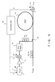
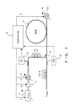
The first concrete configuration is an all-optical signal processing device employing a highly nonlinearmicrostructured fiber 14, a local pumplight source 11, and a means to adjust the optical pump power in order to compensate for the wavelength dependence of the nonlinearity coefficient. Acontrol unit 10 adjusts the wavelength of thelocal pump laser 11 and the center wavelength of theASE filter 12 after theEDFA 17 that boosts the pump light power. In the case of FWM, thecontrol unit 10 also adjusts the center wavelength of thefilter 18 placed after themicrostructured fiber 14. Anoptical coupler 19 combines the signal and the pump light before themicrostructured fiber 14. Thefilter 12 passes only the pump light and eliminates noise light such as ASE noise. Thefilter 18 passes only the output signal light and eliminates all other spectral components.Polarization controllers PCF 14. Matching the polarizations of the pump light and the signal light maximizes efficiency of the nonlinear effect inPCF 14, which is preferable.
The means to adjust the pump power is either:- a) as in Fig. 5, a static
pre-emphasizing filter 13 placed in the optical path between theEDFA 17 and the optical coupler 19: the spectral characteristic of the transmissivity of thepre-emphasizing filter 13 is designed such that the wavelength dependence of the nonlinearity coefficient is compensated by the launched pump power for a given signal wavelength. That is,pre-emphasizing filter 13 attenuates the power of the pump light with an appropriate transmitting characteristics to compensate the wavelength dependence of the nonlinearity coefficient for various wavelengths of the pump light, because, in Fig. 5, the pump light source is a wavelength tunable one. - b1) as in Fig. 6, adjustment of the pump laser output power is conducted by the
control unit 10 and theEDFA 17 with constant gain. The control is based on the measurement of the power of the pump light byphotodiode 21 and of the wavelength of the signal light by theoptical spectrum analyzer 20. - b2) as in Fig. 7, light from the
pump light source 11 with constant laser output power are adjusted byEDFA 17 with variable gain controlled by thecontrol unit 10. - b3) as in Fig. 8, light from the
pump light source 11 with constant laser output power are amplified by theoptical amplifier 17 with constant amplifier gain. The control of the power of the pump light is conducted by avariable attenuator 22 adjusted by thecontrol unit 10.
photodiode 21 in order to monitor the pump light power and provide a feedback signal to thecontrol unit 10.
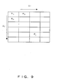
Fig. 9 is a schematic diagram of a look-up table stored in thecontrol unit 10.
The dependence of the nonlinear phase shift on the pump and signal wavelength can be either evaluated experimentally or calculated on the basis of the structure of the microstructured fiber employing equation (1)-(3).
From the obtained information, the pump power that is required to compensate for the wavelength dependence of the nonlinear phase shift is derived and the resulting data summarized either in a look-up table of Fig. 9 or in a fitting function P=P (λs, λp). In the case of a LUT, the wavelengths stored in the table are allocated on the ITU-grid in the specified operational wavelength region of the all-optical signal processing device. In the case of the fitting function a microprocessor calculates the value for a certain combination of (λs, λp) and the coefficients of the fitting function are pre-stored. - a) as in Fig. 5, a static
- 2) The second configuration is an extension of the configurations b1-b3 of the first configuration of the second embodiment.
A part of the signal light is coupled to anoptical spectrum analyzer 30 in order to detect the signal wavelength and provide the information to thecontrol unit 10. Thecontrol unit 10 adjusts the optical power of the pump light on the basis of the information in a look-up table that contains the required pump power data as a function of λpump and λsignal. Thecontrol unit 10 also adjusts the center wavelength of thefilter 18 placed after themicrostructured fiber 14 as a function of λpump and λsignal (FWM) and as a function of λsignal (XPM).
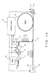
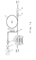
Figs. 10 through 12 show the third configuration of the second embodiment of the present invention. In these figures, like numbers are attached to like elements in the figures of the first configuration. - 3) The third configuration is an all-optical signal-processing device employing a highly nonlinear
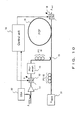
microstructured fiber 14, and a means to adjust the optical pump power in order to compensate for the wavelength dependence of the nonlinearity coefficient. A part of the incoming light, which is used as pump light, is coupled to anoptical spectrum analyzer 30 in order to detect the wavelength and provide the information to thecontrol unit 10. Thecontrol unit 10 adjusts the center wavelength of theASE filter 12 after theEDFA 17 that boosts the pump light power. In the case of FWM, thecontrol unit 10 also adjusts the center wavelength of thefilter 18 placed after the microstructured fiber. Anoptical coupler 19 combines the signal and the pump light before the microstructured fiber.
The means to adjust the pump power is either:- a) as in Fig. 10, the power of the pump light is adjusted by the
pre-emphasizing filter 13. As the other elements are the same as that in Fig. 5, the detailed explanation is omitted. - b1) As in Fig. 11, the power of the pump light is adjusted by the
EDFA 17 by changing the gain of theEDFA 17 under the control of thecontrol unit 10. Further, the wavelength of the signal light is variable in this case. The wavelength of the signal light is adjusted by thecontrol unit 10 and simultaneously the pass wavelength offilter 18 is also adjusted to pass the signal light. The other explanations are omitted as this configuration is similar to that of Fig. 7. - b2) as in Fig. 12, the power of the pump light is adjusted by the
optical attenuator 22 under the control of thecontrol unit 10. The other explanations are omitted as this configuration is similar to that of Fig. 8 and Fig. 11.
control unit 10. - a) as in Fig. 10, the power of the pump light is adjusted by the
- 4) The fourth configuration is an extension of the configuration b1-b2 of the second embodiment. In this configuration, the signal laser light source is wavelength tunable. The control unit adjusts the signal wavelength; moreover, it adjusts the optical power of the pump light on the basis of the information in a look-up table that contains the required pump power data as a function of λpump and λsignal. The control unit also adjusts the center wavelength of the filter placed after the microstructured fiber as a function of λpump and λsignal (FWM) and as a function of λsignal (XPM).
Figs. 13 and 14 show the configurations of the third embodiment of the present invention.
- 1) Figs. 5 through 8 show the first concrete configuration of the second embodiment of the present invention.
- III) The third embodiment solves the problem on a system level, by adjusting the output power by means of an equalizing filter at the output of the highly nonlinear microstructured fiber.
In the third embodiment, the signal light is a WDM signal including a plurality of wavelengths. The WDM signal light is demultiplexed into each wavelength by a wavelength demultiplexing device XYa. The polarization of the light of each wavelength is adjusted independently to each other by means ofpolarization controllers 16a in order to maximize the efficiency of the nonlinear effect inmicrostructured fiber 14. Then, the WDM signal lights are multiplexed by means of a wavelength multiplexing device XYb . The pump light emitted from thepump light source 11 is amplified byEDFA 14 and passes throughfilter 12. Next, its polarization is adjusted. Then, the pump light is coupled together with the signal lights and inputted toPCF 14. The magnitude of the nonlinear effect inPCF 14 is different for each signal wavelength, resulting in a difference in intensity of each signal wavelength . Therefore, the intensity of each wavelength of the WDM light after affected by the nonlinear effect inPCF 14 is made constant by the equalizingfilter 35 after passing through thefilter 18. By eliminating the result of the wavelength dependency of the nonlinear effect in PCF 14 (difference in intensity of each wavelength), a virtually wavelength independent operation of the signal processing device is obtained.- 1) In the first configuration of the third embodiment, as in Fig. 13, an equalizing
filter 35 is placed at the output of thePCF 14 in order to compensate for the wavelength dependence of the nonlinearity coefficient. - 2) In the second configuration of the third embodiment, as in Fig. 14, the pump wavelength and the equalizing
filter 35 are adjustable. The spectral characteristic of the transmissivity of the equalizingfilter 35 is adapted such that the resulting power tilt of the output spectrum due to the wavelength dependence of the nonlinearity coefficient is canceled.
- 1) In the first configuration of the third embodiment, as in Fig. 13, an equalizing
- IV) The fourth embodiment solves the problem on a system level, by adjusting the signal input powers by means of an equalizing
filter 40 at the input of the highly nonlinear microstructured fiber. Based on the fact that the intensity of output light fromPCF 14 is linearly proportional to the intensity of input light toPCF 14, the intensity of input light is adjusted by the equalizingfilter 40 beforePCF 14.- 1) In the first configuration of the fourth embodiment, as in Fig. 15, a equalizing
filter 40 is placed at the input of the highly nonlinearmicrostructured fiber 14 before thecoupler 19 in order to compensate for the wavelength dependence of the nonlinearity coefficient. The other components are similar to that of Fig. 13. Therefore, further explanations are omitted. - 2) In the second configuration of the fourth embodiment, as in Fig. 16, the pump wavelength and the equalizing
filter 40 are adjustable. The spectral characteristic of the transimssivity of the equalizingfilter 40 is adapted such that the resulting power tilt of the output spectrum due to the wavelength dependence of the nonlinearity coefficient is canceled. The other components are similar to that of Fig. 14. Therefore, further explanations are omitted.
- 1) In the first configuration of the fourth embodiment, as in Fig. 15, a equalizing
- In an arrangement there is provided a microstructured optical fiber which has a nonlinear refractive index profile in which the nonlinear refractive index increases in outward radial direction from core center.
- In said arrangement there may be further provided the microstructured optical fiber, wherein the nonlinear refractive index profile has a shape of an inverse of intensity distribution of a pump light or signal light in cross section.
- In said arrangement there may be further provided a microstructured optical fiber, wherein the nonlinear refractive index profile becomes constant at an outside radial region from a predetermined radius in cross section.
- In said arrangement there may be further provided a microstructured optical fiber, wherein the nonlinear refractive index increases stepwise in outward radial direction from the core center.
- In a further arrangement there may be provided an optical signal processing device, comprising: a pump light source; a nonlinear microstructured fiber receiving a pump light and a signal light, and causing nonlinear effect on the signal light depending on an intensity of the pump light; an adjustment means for adjusting an intensity of the pump light; and a control means for controlling an intensity of the pump light by adjusting the adjustment means so that a wavelength dependence of the nonlinear effect on the signal light is canceled.
- In said further arrangement there may further be provided an optical signal processing device, wherein the adjustment means is a pre-emphasizing filter.
- In said further arrangement there may further be provided an optical signal processing device, wherein the adjustment means is an optical amplifier.
- In said further arrangement there may further be provided an optical signal processing device, wherein the adjustment means is an optical attenuator.
- In said further arrangement there may further be provided as a modification the optical signal processing device, wherein the control means controls an intensity of the pump light based on data in a look-up table containing a required power as a function of the signal wavelength and the pump wavelength.
- In said further arrangement there may further be provided as a modification the optical signal processing device, wherein the control means controls the intensity of the pump light based on data obtained from a predetermined function describing a required power as a function of the signal wavelength and the pump wavelength.
- In said modifications there may further be provided the optical signal processing device, further comprising: an optical spectrum analyzer monitoring the signal wavelength or the pump wavelength in order to provide information on the signal wavelength or the pump wavelength to the control means.
Claims (8)
- An optical signal processing device, comprising:a pump light source;a nonlinear microstructured fiber receiving a pump light and a signal light, and causing nonlinear effect on the signal light depending on an intensity of the pump light; andan equalizing filter adjusting a resultant signal intensity caused by a wavelength dependence of the nonlinear effect on the signal light.
- The optical signal processing device according to claim 1, wherein
the equalizing filter is an adjustable filter of a spectral characteristic of transmissivity, and
further comprising:a control means controlling the spectral characteristic of transimissivity of the equalizing filter so that a tilt of an output signal from the nonlinear microstructured fiber caused by the wavelength dependence of the nonlinear effect on the signal light is canceled. - The optical signal processing device according to claim 1, wherein
the equalizing filter is placed at the output side of the nonlinear microstructured fiber. - The optical signal processing device according to claim 1, wherein
the equalizing filter is placed at the input side of the nonlinear microstructured fiber. - The optical signal processing device according to claim 2, wherein
the control means controls the tilt of the output signal from the microstructured fiber based on data in a look-up table containing a required power as a function of the signal wavelength and the pump wavelength. - The optical signal processing device according to claim 2, wherein
the control means controls the tilt of the input signal from the microstructured fiber based on data in a look-up table containing a required power as a function of the signal wavelength and the pump wavelength. - The optical signal processing device according to claim 2, wherein
the control means controls a tilt of the output signal from the microstructured fiber based on data obtained from a predetermined function describing a required power as a function of the signal wavelength and the pump wavelength. - The optical signal processing device according to claim 2, wherein
the control means controls the tilt of the input signal from the microstructured fiber based on data obtained from a predetermined function describing a required power as a function of the signal wavelength and the pump wavelength.
Applications Claiming Priority (2)
| Application Number | Priority Date | Filing Date | Title |
|---|---|---|---|
| JP2004101411A JP4451696B2 (en) | 2004-03-30 | 2004-03-30 | Device for canceling wavelength dependence of nonlinear coefficient of microstructured fiber |
| EP04026807A EP1582915B1 (en) | 2004-03-30 | 2004-11-11 | Microstructured fibre with non-linear index profile in the core |
Related Parent Applications (2)
| Application Number | Title | Priority Date | Filing Date |
|---|---|---|---|
| EP04026807.0 Division | 2004-11-11 | ||
| EP04026807A Division EP1582915B1 (en) | 2004-03-30 | 2004-11-11 | Microstructured fibre with non-linear index profile in the core |
Publications (3)
| Publication Number | Publication Date |
|---|---|
| EP1734403A2 true EP1734403A2 (en) | 2006-12-20 |
| EP1734403A3 EP1734403A3 (en) | 2006-12-27 |
| EP1734403B1 EP1734403B1 (en) | 2011-10-12 |
Family
ID=34880006
Family Applications (3)
| Application Number | Title | Priority Date | Filing Date |
|---|---|---|---|
| EP07021081A Withdrawn EP1887420A3 (en) | 2004-03-30 | 2004-11-11 | Device for canceling the wavelenght dependence of the nonlinearity coefficient of microstructured fibers and microstructured fiber with nonlinear core refractive index profile |
| EP06018850A Expired - Lifetime EP1734403B1 (en) | 2004-03-30 | 2004-11-11 | Device for canceling the wavelength dependence of the nonlinearity coefficient of microstructured fibers |
| EP04026807A Expired - Lifetime EP1582915B1 (en) | 2004-03-30 | 2004-11-11 | Microstructured fibre with non-linear index profile in the core |
Family Applications Before (1)
| Application Number | Title | Priority Date | Filing Date |
|---|---|---|---|
| EP07021081A Withdrawn EP1887420A3 (en) | 2004-03-30 | 2004-11-11 | Device for canceling the wavelenght dependence of the nonlinearity coefficient of microstructured fibers and microstructured fiber with nonlinear core refractive index profile |
Family Applications After (1)
| Application Number | Title | Priority Date | Filing Date |
|---|---|---|---|
| EP04026807A Expired - Lifetime EP1582915B1 (en) | 2004-03-30 | 2004-11-11 | Microstructured fibre with non-linear index profile in the core |
Country Status (3)
| Country | Link |
|---|---|
| US (1) | US8078026B2 (en) |
| EP (3) | EP1887420A3 (en) |
| JP (1) | JP4451696B2 (en) |
Cited By (2)
| Publication number | Priority date | Publication date | Assignee | Title |
|---|---|---|---|---|
| US8785884B2 (en) | 2010-01-22 | 2014-07-22 | Fianium Ltd. | Optical sources |
| US8902495B2 (en) | 2011-11-01 | 2014-12-02 | Fianium Ltd. | Laser or amplifier optical device pumped or seeded with nonlinearly generated light |
Families Citing this family (6)
| Publication number | Priority date | Publication date | Assignee | Title |
|---|---|---|---|---|
| JP5027434B2 (en) | 2006-03-28 | 2012-09-19 | 富士通株式会社 | Device for shaping optical signal waveform |
| JP4754388B2 (en) * | 2006-03-31 | 2011-08-24 | 富士通株式会社 | Optical transmission system |
| CN102722060A (en) * | 2012-07-13 | 2012-10-10 | 西南交通大学 | Single-pump optical fiber parameter amplifier for realizing gain optimization by filtering idler-frequency light |
| US9169727B2 (en) | 2012-12-04 | 2015-10-27 | Schlumberger Technology Corporation | Scattering detection from downhole optical spectra |
| US8824848B1 (en) * | 2013-06-10 | 2014-09-02 | Sumitomo Electric Industries, Ltd. | Multimode optical fiber including a core and a cladding |
| CN113419304B (en) * | 2021-06-11 | 2022-06-17 | 太原理工大学 | A silicon-based valley photonic crystal structure for wavelength division multiplexing in the optical communication band |
Family Cites Families (27)
| Publication number | Priority date | Publication date | Assignee | Title |
|---|---|---|---|---|
| JPH05327104A (en) * | 1992-05-21 | 1993-12-10 | Sumitomo Electric Ind Ltd | Optical fiber amplifier |
| US5559921A (en) * | 1994-06-24 | 1996-09-24 | Sumitomo Electric Industries, Ltd. | Single mode optical fiber |
| US5715346A (en) * | 1995-12-15 | 1998-02-03 | Corning Incorporated | Large effective area single mode optical waveguide |
| SE509968C2 (en) * | 1997-02-14 | 1999-03-29 | Ericsson Telefon Ab L M | Variable amplifier optical amplifier |
| JP2000151515A (en) * | 1998-03-19 | 2000-05-30 | Fujitsu Ltd | Adjustment of gain and signal level of cascaded optical amplifiers |
| JP2001100817A (en) * | 1999-09-30 | 2001-04-13 | Toyoda Mach Works Ltd | Monitoring device for sequential function chart type programmable controller |
| US6859598B2 (en) | 2000-01-21 | 2005-02-22 | Sumitomo Electric Industries, Ltd. | Microstructured optical fiber |
| JP4310923B2 (en) | 2000-01-21 | 2009-08-12 | 住友電気工業株式会社 | Optical fiber |
| US6567777B1 (en) * | 2000-08-02 | 2003-05-20 | Motorola, Inc. | Efficient magnitude spectrum approximation |
| WO2002014944A1 (en) * | 2000-08-11 | 2002-02-21 | Crystal Fibre A/S | Optical wavelength converter |
| US6504645B1 (en) | 2000-08-29 | 2003-01-07 | Lucent Technologies Inc. | Chalcogenide glass based Raman optical amplifier |
| US6954575B2 (en) * | 2001-03-16 | 2005-10-11 | Imra America, Inc. | Single-polarization high power fiber lasers and amplifiers |
| AU2002246261A1 (en) * | 2001-04-11 | 2002-10-28 | University Of Southampton | Sources of, and methods for generating, optical pulses |
| CA2443037A1 (en) | 2001-04-11 | 2002-10-24 | Crystal Fibre A/S | Dual core photonic crystal fibers (pcf) with special dispersion properties |
| US6943937B2 (en) * | 2001-05-17 | 2005-09-13 | Avanex Corporation | Optical amplifier performance controller and method of use |
| CN1369733A (en) * | 2001-06-27 | 2002-09-18 | 天津大学 | Distributed optical-fibre Raman Amplifier using novel pump source |
| DE60234795D1 (en) | 2001-06-29 | 2010-02-04 | Sumitomo Electric Industries | Pump light source unit, Raman amplifier and optical transmission system |
| US6690505B1 (en) * | 2001-09-28 | 2004-02-10 | Onetta, Inc. | Optical network equipment with gain transient control and automatic drift compensation |
| US6788862B2 (en) * | 2002-05-14 | 2004-09-07 | Corning, Inc. | Microstructured optical waveguide having large optical nonlinearity |
| JP4137515B2 (en) | 2002-05-17 | 2008-08-20 | 日本電信電話株式会社 | Dispersion-shifted optical fiber |
| US6847771B2 (en) | 2002-06-12 | 2005-01-25 | Corning Incorporated | Microstructured optical fibers and preforms and methods for fabricating microstructured optical fibers |
| US7072589B2 (en) * | 2002-09-16 | 2006-07-04 | Fitel Usa Corp. | Method and apparatus for controlling the power level in an optical regenerator |
| JP2004177817A (en) * | 2002-11-28 | 2004-06-24 | Sumitomo Electric Ind Ltd | Optical fiber and optical module |
| US7136558B2 (en) * | 2003-04-29 | 2006-11-14 | Nortel Networks Limited | Optical waveguide |
| US7257302B2 (en) | 2003-06-03 | 2007-08-14 | Imra America, Inc. | In-line, high energy fiber chirped pulse amplification system |
| GB2403816A (en) * | 2003-07-11 | 2005-01-12 | Fujitsu Ltd | Optical device with radial discontinuities in the refractive index |
| US7403689B2 (en) | 2003-11-19 | 2008-07-22 | Corning Incorporated | Active photonic band-gap optical fiber |
-
2004
- 2004-03-30 JP JP2004101411A patent/JP4451696B2/en not_active Expired - Fee Related
- 2004-11-11 EP EP07021081A patent/EP1887420A3/en not_active Withdrawn
- 2004-11-11 EP EP06018850A patent/EP1734403B1/en not_active Expired - Lifetime
- 2004-11-11 EP EP04026807A patent/EP1582915B1/en not_active Expired - Lifetime
- 2004-11-30 US US10/999,059 patent/US8078026B2/en not_active Expired - Fee Related
Cited By (6)
| Publication number | Priority date | Publication date | Assignee | Title |
|---|---|---|---|---|
| US8785884B2 (en) | 2010-01-22 | 2014-07-22 | Fianium Ltd. | Optical sources |
| US10527907B2 (en) | 2010-01-22 | 2020-01-07 | Nkt Photonics A/S | Optical sources |
| US11675245B2 (en) | 2010-01-22 | 2023-06-13 | Nkt Photonics A/S | Optical sources |
| US12578618B2 (en) | 2010-01-22 | 2026-03-17 | Nkt Photonics A/S | Optical sources |
| US8902495B2 (en) | 2011-11-01 | 2014-12-02 | Fianium Ltd. | Laser or amplifier optical device pumped or seeded with nonlinearly generated light |
| US9246296B2 (en) | 2011-11-01 | 2016-01-26 | Fianium Ltd | Laser or amplifier optical device seeded with nonlinearly generated light |
Also Published As
| Publication number | Publication date |
|---|---|
| EP1582915A3 (en) | 2005-11-09 |
| EP1582915B1 (en) | 2012-10-31 |
| JP4451696B2 (en) | 2010-04-14 |
| EP1887420A3 (en) | 2008-04-23 |
| JP2005284190A (en) | 2005-10-13 |
| EP1734403B1 (en) | 2011-10-12 |
| US20050220431A1 (en) | 2005-10-06 |
| EP1734403A3 (en) | 2006-12-27 |
| US8078026B2 (en) | 2011-12-13 |
| EP1582915A2 (en) | 2005-10-05 |
| EP1887420A2 (en) | 2008-02-13 |
Similar Documents
| Publication | Publication Date | Title |
|---|---|---|
| US6693740B2 (en) | Dispersion managed discrete Raman amplifiers | |
| EP2682813B1 (en) | Optical amplifier, optical amplifying system, wavelength converter, optical amplification method, and optical communication system | |
| EP1628148B1 (en) | Polarization insensitive optical fibre | |
| JP5877280B2 (en) | Optical amplifier, optical amplification system, wavelength converter, and optical communication system | |
| US20100061410A1 (en) | System and method for controlling nonlinearities in laser units | |
| US6266463B1 (en) | Chirped optical fibre grating | |
| EP1456918A1 (en) | Raman amplification using a microstructured fiber | |
| Nazemosadat et al. | Design of highly nonlinear few-mode fiber for C-band optical parametric amplification | |
| US6317538B1 (en) | Optical waveguide device and optical device having long-period grating | |
| US8078026B2 (en) | Device for canceling the wavelength dependence of the nonlinearity coefficient of microstructured fibers | |
| US20070160092A1 (en) | Broad-band light source | |
| US6865328B2 (en) | Positive dispersion optical fiber | |
| Moon et al. | Switchable dual-wavelength erbium-doped fiber ring laser assisted with four-wave mixing of dispersion-shifted fiber | |
| US20120281719A1 (en) | Method and Apparatus for Controlling Mode Coupling in High Power Laser System | |
| US7079737B1 (en) | Devices and methods for dynamic dispersion compensation | |
| Kakkar et al. | Segmented-clad fiber design for tunable leakage loss | |
| Deb et al. | Effect of HOD parameters on gain and bandwidth of parametric amplifiers for near-zero ultra-flat dispersion profile | |
| US20020181878A1 (en) | Dynamic chromatic dispersion control using coupled optical waveguides | |
| Rastogi et al. | Large effective area all-solid dispersion compensating fiber | |
| US8406584B2 (en) | Fiber optic device | |
| Han et al. | Design of an improved microstructure fibre for broadband dispersion compensation with low nonlinearity |
Legal Events
| Date | Code | Title | Description |
|---|---|---|---|
| PUAI | Public reference made under article 153(3) epc to a published international application that has entered the european phase |
Free format text: ORIGINAL CODE: 0009012 |
|
| PUAL | Search report despatched |
Free format text: ORIGINAL CODE: 0009013 |
|
| AC | Divisional application: reference to earlier application |
Ref document number: 1582915 Country of ref document: EP Kind code of ref document: P |
|
| AK | Designated contracting states |
Kind code of ref document: A2 Designated state(s): DE FR GB |
|
| AX | Request for extension of the european patent |
Extension state: AL HR LT LV MK YU |
|
| AK | Designated contracting states |
Kind code of ref document: A3 Designated state(s): DE FR GB |
|
| AX | Request for extension of the european patent |
Extension state: AL HR LT LV MK YU |
|
| RTI1 | Title (correction) |
Free format text: DEVICE FOR CANCELING THE WAVELENGHT DEPENDENCE OF THE NONLINEARITY COEFFICIENT OF MICROSTRUCTURED FIBERS AND MICROSTRUCTURED FIBER WITH NONLINEAR CORE REFRACTIVE INDEX PROFILE |
|
| 17P | Request for examination filed |
Effective date: 20070604 |
|
| AKX | Designation fees paid |
Designated state(s): DE FR GB |
|
| 17Q | First examination report despatched |
Effective date: 20070830 |
|
| RTI1 | Title (correction) |
Free format text: DEVICE FOR CANCELING THE WAVELENGHT DEPENDENCE OF THE NONLINEARITY COEFFICIENT OF MICROSTRUCTURED FIBERS |
|
| GRAP | Despatch of communication of intention to grant a patent |
Free format text: ORIGINAL CODE: EPIDOSNIGR1 |
|
| GRAS | Grant fee paid |
Free format text: ORIGINAL CODE: EPIDOSNIGR3 |
|
| RTI1 | Title (correction) |
Free format text: DEVICE FOR CANCELING THE WAVELENGTH DEPENDENCE OF THE NONLINEARITY COEFFICIENT OF MICROSTRUCTURED FIBERS |
|
| GRAA | (expected) grant |
Free format text: ORIGINAL CODE: 0009210 |
|
| AC | Divisional application: reference to earlier application |
Ref document number: 1582915 Country of ref document: EP Kind code of ref document: P |
|
| AK | Designated contracting states |
Kind code of ref document: B1 Designated state(s): DE FR GB |
|
| REG | Reference to a national code |
Ref country code: GB Ref legal event code: FG4D |
|
| REG | Reference to a national code |
Ref country code: DE Ref legal event code: R096 Ref document number: 602004034870 Country of ref document: DE Effective date: 20111208 |
|
| PLBE | No opposition filed within time limit |
Free format text: ORIGINAL CODE: 0009261 |
|
| STAA | Information on the status of an ep patent application or granted ep patent |
Free format text: STATUS: NO OPPOSITION FILED WITHIN TIME LIMIT |
|
| 26N | No opposition filed |
Effective date: 20120713 |
|
| REG | Reference to a national code |
Ref country code: DE Ref legal event code: R097 Ref document number: 602004034870 Country of ref document: DE Effective date: 20120713 |
|
| REG | Reference to a national code |
Ref country code: FR Ref legal event code: PLFP Year of fee payment: 12 |
|
| REG | Reference to a national code |
Ref country code: FR Ref legal event code: PLFP Year of fee payment: 13 |
|
| REG | Reference to a national code |
Ref country code: FR Ref legal event code: PLFP Year of fee payment: 14 |
|
| REG | Reference to a national code |
Ref country code: FR Ref legal event code: PLFP Year of fee payment: 15 |
|
| PGFP | Annual fee paid to national office [announced via postgrant information from national office to epo] |
Ref country code: GB Payment date: 20210930 Year of fee payment: 18 |
|
| PGFP | Annual fee paid to national office [announced via postgrant information from national office to epo] |
Ref country code: DE Payment date: 20210929 Year of fee payment: 18 |
|
| PGFP | Annual fee paid to national office [announced via postgrant information from national office to epo] |
Ref country code: FR Payment date: 20211018 Year of fee payment: 18 |
|
| REG | Reference to a national code |
Ref country code: DE Ref legal event code: R119 Ref document number: 602004034870 Country of ref document: DE |
|
| GBPC | Gb: european patent ceased through non-payment of renewal fee |
Effective date: 20221111 |
|
| PG25 | Lapsed in a contracting state [announced via postgrant information from national office to epo] |
Ref country code: GB Free format text: LAPSE BECAUSE OF NON-PAYMENT OF DUE FEES Effective date: 20221111 Ref country code: DE Free format text: LAPSE BECAUSE OF NON-PAYMENT OF DUE FEES Effective date: 20230601 |
|
| PG25 | Lapsed in a contracting state [announced via postgrant information from national office to epo] |
Ref country code: FR Free format text: LAPSE BECAUSE OF NON-PAYMENT OF DUE FEES Effective date: 20221130 |