EP1734257A1 - Centrifugal fan - Google Patents
Centrifugal fan Download PDFInfo
- Publication number
- EP1734257A1 EP1734257A1 EP05110247A EP05110247A EP1734257A1 EP 1734257 A1 EP1734257 A1 EP 1734257A1 EP 05110247 A EP05110247 A EP 05110247A EP 05110247 A EP05110247 A EP 05110247A EP 1734257 A1 EP1734257 A1 EP 1734257A1
- Authority
- EP
- European Patent Office
- Prior art keywords
- centrifugal fan
- frame
- air inlet
- barricade
- air outlet
- Prior art date
- Legal status (The legal status is an assumption and is not a legal conclusion. Google has not performed a legal analysis and makes no representation as to the accuracy of the status listed.)
- Granted
Links
Images



Classifications
-
- F—MECHANICAL ENGINEERING; LIGHTING; HEATING; WEAPONS; BLASTING
- F04—POSITIVE - DISPLACEMENT MACHINES FOR LIQUIDS; PUMPS FOR LIQUIDS OR ELASTIC FLUIDS
- F04D—NON-POSITIVE-DISPLACEMENT PUMPS
- F04D29/00—Details, component parts, or accessories
- F04D29/40—Casings; Connections of working fluid
- F04D29/42—Casings; Connections of working fluid for radial or helico-centrifugal pumps
- F04D29/4206—Casings; Connections of working fluid for radial or helico-centrifugal pumps especially adapted for elastic fluid pumps
- F04D29/4213—Casings; Connections of working fluid for radial or helico-centrifugal pumps especially adapted for elastic fluid pumps suction ports
-
- F—MECHANICAL ENGINEERING; LIGHTING; HEATING; WEAPONS; BLASTING
- F04—POSITIVE - DISPLACEMENT MACHINES FOR LIQUIDS; PUMPS FOR LIQUIDS OR ELASTIC FLUIDS
- F04D—NON-POSITIVE-DISPLACEMENT PUMPS
- F04D29/00—Details, component parts, or accessories
- F04D29/08—Sealings
- F04D29/083—Sealings especially adapted for elastic fluid pumps
-
- F—MECHANICAL ENGINEERING; LIGHTING; HEATING; WEAPONS; BLASTING
- F04—POSITIVE - DISPLACEMENT MACHINES FOR LIQUIDS; PUMPS FOR LIQUIDS OR ELASTIC FLUIDS
- F04D—NON-POSITIVE-DISPLACEMENT PUMPS
- F04D29/00—Details, component parts, or accessories
- F04D29/40—Casings; Connections of working fluid
- F04D29/42—Casings; Connections of working fluid for radial or helico-centrifugal pumps
- F04D29/4206—Casings; Connections of working fluid for radial or helico-centrifugal pumps especially adapted for elastic fluid pumps
- F04D29/4226—Fan casings
Definitions
- the invention relates to a frame for a centrifugal fan, and in particular to a frame for a centrifugal fan preventing impurities from entering the interior thereof and reducing reflow of air in a system.
- a conventional centrifugal fan comprises a frame 10, a motor (not shown), and an impeller 30.
- the frame 10 comprises an air inlet 11 and an air outlet (not shown).
- the motor is disposed in the frame 10, for activating the impeller 30 which comprises a hub 31, a base plate 32, and a plurality of blades 33 formed on the base plate 32. Air enters the centrifugal fan via the air inlet 11 and flows with the rotation of the impeller 30 and exits from the air outlet.
- the conventional centrifugal fan is applied in a system 40 in which electronic members (not shown) are disposed.
- An air inlet 41 is formed on one side of a housing of the system 40.
- heat in the system 40 is dissipated by the centrifugal fan. Outside air enters the centrifugal fan via the air inlet 41 of the system 40. Air output from the air outlet of the centrifugal fan is forwarded to the interior of the system 40.
- the aforementioned operation of heat dissipation has a drawback.
- An airflow output from the air outlet of the centrifugal fan causes reflow of air, reducing heat dissipation from the system 40.
- FIG. 3 To reduce the reflow of air, another system, as shown in FIG. 3, comprises a guide plate 42 disposed in a housing of the system and tightly abutting the centrifugal fan to reduce the reflow of air.
- the guide plate 42 abuts the centrifugal fan by a surface thereof contacting a turning corner on an outer frame of the centrifugal fan. Accordingly, the guide plate 42 contacts the centrifugal fan merely in a linear manner. Thus, reflow of air is also easily generated when linear contact between the guide plate 42 and the centrifugal fan is incomplete.
- impurities such as dust and water drops
- the impurities may also enter the centrifugal fan, causing damage thereto.
- an embodiment of the invention provides a frame for a centrifugal fan.
- the frame comprises an air inlet and an air outlet.
- a first barricade is formed on one side of the air inlet and extends outward, preventing impurities from entering the air inlet.
- Another embodiment of the invention provides a frame for a centrifugal fan.
- the frame comprises an air inlet and an air outlet.
- a second barricade is formed on part of the periphery of the air outlet and extends outward. The second barricade tightly abuts a system for preventing reflow of air, enhancing heat dissipation, and increasing rigidity of the frame.
- a centrifugal fan comprising a frame, an impeller, and a motor.
- the frame comprises an air inlet and an air outlet.
- a barricade is formed on one side of the air inlet and extends outward, preventing impurities from entering the air inlet.
- the impeller is disposed in the frame.
- the motor is disposed in the frame for activating the impeller.
- the centrifugal fan comprises a hollow frame 50, an impeller 60, and a motor (not shown) for activating the impeller 60.
- the motor and impeller 60 are disposed in the frame 50.
- the frame 50 comprises a top cover 501 and a bottom cover 502.
- the frame 50 further comprises an axial air inlet 503 and a sideward air outlet 504.
- the air inlet 503 penetrates the top cover 501 and is formed along an axial direction thereof.
- the air outlet 504 is formed between a periphery of the top cover 501 and a corresponding periphery of the bottom cover 502.
- the top cover 501 comprises a plurality of U-shaped retaining rings (first engaging portions) 5011 downwardly formed on the periphery thereof.
- the bottom cover 502 comprises a plurality of protrusions (second engaging portions) 5021 formed on the sidewall thereof.
- the U-shaped retaining rings 5011 respectively engage the protrusions 5021 to form the frame 50.
- the profile of the frame 50 is substantially D-shaped. Namely, the air outlet 504 outwardly expands from interior of the frame 50 and with respect to an opposite end thereof.
- the profile of the frame 50 is designed according to the flow of air therein, normalizing the speed and amount of airflow output from the air outlet 504.
- a first barricade 505 is axially and upwardly formed on part of the periphery of the air inlet 503 of the top cover 501.
- the height, curved length, and forming position of the first barricade 505 can be designed as required.
- the first barricade 505 may not be formed on the periphery of the air inlet 503, the curvature thereof may not be the same as that of the periphery of the air inlet 503, and the barricade 505 may not be vertically and upwardly formed.
- the first barricade 505 may be separated from the air inlet 503 by a distance, the curvature thereof may be greater or less than that of the periphery of the air inlet 503, and the barricade 505 may be upwardly formed with any sloped angle.
- a second barricade 506 is formed on part of the periphery of the air outlet 504 and extends outwardly and axially.
- the height of the second barricade 506 can be designed as required.
- the air inlet 503 and air outlet 504 can be close to each other.
- the second barricade 506 can enhance rigidity thereof.
- part of the periphery of the air inlet 503 near one side of the air outlet 504 is straight and covers part of blades of the impeller 60. Reflow of air can thus be reduced.
- the centrifugal fan can be applied in a system 40 with a housing. Electronic members (not shown) and the centrifugal fan are disposed in the housing. An air inlet 41 is formed on one side of the housing. Heat in the system 40 is dissipated by operation of the centrifugal fan. Specifically, air enters the centrifugal fan via the air inlet 41 of the system 40 and is forwarded to the interior of the system 40 via the air outlet 504 of the centrifugal fan.
- the first barricade 505 of the frame 50 faces the air inlet 41 of the system 40, which prevents impurities, such as dust and liquid, from entering the centrifugal fan.
- the centrifugal fan is thus not damaged.
- the first barricade 505 is mainly to prevent the impurities from entering the centrifugal fan via the air inlet 41 of the system 40, the first barricade 505 can also be designed to have a straight and flat profile. Nevertheless, the profile and forming position of the first barricade 505 shown in FIG. 4A and FIG. 6A provide a better prevention of impurities entering the centrifugal fan and thus do not adversely affect flow of air.
- the air inlet 41 may be formed on different sides of the housing of the system 40.
- the first barricade 505 may be formed in different positions on the centrifugal fan, as shown in FIG. 7A and FIG. 7B.
- the centrifugal fan can be applied in another system 40 with a housing and a guide plate 42.
- the guide plate 42 is disposed in the housing.
- the second barricade 506 of the frame 50 tightly abuts the guide plate 42, such that reflow of air is reduced and heat dissipation of the system 40 is enhanced.
- the second barricade 506 can be designed as required.
- a top end (or an extending end) of the second barricade 506 can be formed with a planar, curved, or sloped surface.
- the first barricade prevents impurities from entering, and the second barricade tightly abuts the guide plate of the system.
- the second barricade tightly abuts the guide plate of the system.
Landscapes
- Engineering & Computer Science (AREA)
- Mechanical Engineering (AREA)
- General Engineering & Computer Science (AREA)
- Structures Of Non-Positive Displacement Pumps (AREA)
Abstract
Description
- The invention relates to a frame for a centrifugal fan, and in particular to a frame for a centrifugal fan preventing impurities from entering the interior thereof and reducing reflow of air in a system.
- Referring to FIG. 1, a conventional centrifugal fan comprises a
frame 10, a motor (not shown), and animpeller 30. Theframe 10 comprises anair inlet 11 and an air outlet (not shown). The motor is disposed in theframe 10, for activating theimpeller 30 which comprises ahub 31, abase plate 32, and a plurality ofblades 33 formed on thebase plate 32. Air enters the centrifugal fan via theair inlet 11 and flows with the rotation of theimpeller 30 and exits from the air outlet. - Referring to FIG. 2A and FIG. 2B, the conventional centrifugal fan is applied in a
system 40 in which electronic members (not shown) are disposed. Anair inlet 41 is formed on one side of a housing of thesystem 40. As shown in FIG. 2B, heat in thesystem 40 is dissipated by the centrifugal fan. Outside air enters the centrifugal fan via theair inlet 41 of thesystem 40. Air output from the air outlet of the centrifugal fan is forwarded to the interior of thesystem 40. The aforementioned operation of heat dissipation, however, has a drawback. An airflow output from the air outlet of the centrifugal fan causes reflow of air, reducing heat dissipation from thesystem 40. - To reduce the reflow of air, another system, as shown in FIG. 3, comprises a
guide plate 42 disposed in a housing of the system and tightly abutting the centrifugal fan to reduce the reflow of air. - Specifically, as shown in FIG. 3, the
guide plate 42 abuts the centrifugal fan by a surface thereof contacting a turning corner on an outer frame of the centrifugal fan. Accordingly, theguide plate 42 contacts the centrifugal fan merely in a linear manner. Thus, reflow of air is also easily generated when linear contact between theguide plate 42 and the centrifugal fan is incomplete. - Moreover, as the
air inlet 41 of thesystem 40 is connected to the exterior thereof, impurities, such as dust and water drops, may enter thesystem 40 via theair inlet 41. The impurities may also enter the centrifugal fan, causing damage thereto. - Hence, there is a need for a frame of a centrifugal fan to reduce reflow of air in a system and enhance heat dissipation thereof. In addition, external impurities can be reduced in the centrifugal fan such that damage thereto is prevented.
- Accordingly, an embodiment of the invention provides a frame for a centrifugal fan. The frame comprises an air inlet and an air outlet. A first barricade is formed on one side of the air inlet and extends outward, preventing impurities from entering the air inlet.
- Another embodiment of the invention provides a frame for a centrifugal fan. The frame comprises an air inlet and an air outlet. A second barricade is formed on part of the periphery of the air outlet and extends outward. The second barricade tightly abuts a system for preventing reflow of air, enhancing heat dissipation, and increasing rigidity of the frame.
- Yet another embodiment of the invention provides a centrifugal fan comprising a frame, an impeller, and a motor. The frame comprises an air inlet and an air outlet. A barricade is formed on one side of the air inlet and extends outward, preventing impurities from entering the air inlet. The impeller is disposed in the frame. The motor is disposed in the frame for activating the impeller.
- The invention can be more fully understood by reading the subsequent detailed description and examples with references made to the accompanying drawings, wherein:
- FIG. 1 is an exploded perspective view of a conventional centrifugal fan;
- FIG. 2A is a schematic top view of a conventional centrifugal fan applied in a system;
- FIG. 2B is a schematic side view of a conventional centrifugal fan applied in a system;
- FIG. 3 is a schematic side view of a conventional centrifugal fan applied in another system;
- FIG. 4A is a schematic perspective view of the centrifugal fan of an embodiment of the invention;
- FIG. 4B is a schematic side view of FIG. 4A;
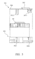
- FIG. 5 is an exploded side view of FIG. 4A;
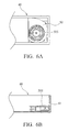
- FIG. 6A is a schematic top view of a centrifugal fan of an embodiment of the invention applied in a system;
- FIG. 6B is a schematic side view of a centrifugal fan of an embodiment of the invention applied in a system;
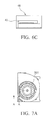
- FIG. 6C is a schematic front view of a centrifugal fan of an embodiment of the invention applied in a system;
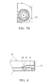
- FIG. 7A is a schematic top view of a first barricade of a centrifugal fan of an embodiment of the invention;
- FIG. 7B is another schematic top view of a first barricade of a centrifugal fan of an embodiment of the invention;
- FIG. 8 is a schematic side view of a centrifugal fan of an embodiment of the invention applied in another system; and
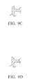
- FIGs. 9A, 9B, 9C, and 9D are partial views of different top ends of the second barricades of the centrifugal fan of the invention.
- Referring to FIGs. 4A, 4B, and 5, the centrifugal fan comprises a
hollow frame 50, animpeller 60, and a motor (not shown) for activating theimpeller 60. The motor andimpeller 60 are disposed in theframe 50. - The
frame 50 comprises atop cover 501 and abottom cover 502. Theframe 50 further comprises an axial air inlet 503 and asideward air outlet 504. Specifically, the air inlet 503 penetrates thetop cover 501 and is formed along an axial direction thereof. Theair outlet 504 is formed between a periphery of thetop cover 501 and a corresponding periphery of thebottom cover 502. Thetop cover 501 comprises a plurality of U-shaped retaining rings (first engaging portions) 5011 downwardly formed on the periphery thereof. Thebottom cover 502 comprises a plurality of protrusions (second engaging portions) 5021 formed on the sidewall thereof. The U-shaped retaining rings 5011 respectively engage theprotrusions 5021 to form theframe 50. In this embodiment, the profile of theframe 50 is substantially D-shaped. Namely, theair outlet 504 outwardly expands from interior of theframe 50 and with respect to an opposite end thereof. The profile of theframe 50 is designed according to the flow of air therein, normalizing the speed and amount of airflow output from theair outlet 504. Thus, heat generated by a heat source with a large area can be dissipated, and space required by theframe 50 can be reduced. - Moreover, a
first barricade 505 is axially and upwardly formed on part of the periphery of the air inlet 503 of thetop cover 501. The height, curved length, and forming position of thefirst barricade 505 can be designed as required. Specifically, thefirst barricade 505 may not be formed on the periphery of the air inlet 503, the curvature thereof may not be the same as that of the periphery of the air inlet 503, and thebarricade 505 may not be vertically and upwardly formed. Namely, thefirst barricade 505 may be separated from the air inlet 503 by a distance, the curvature thereof may be greater or less than that of the periphery of the air inlet 503, and thebarricade 505 may be upwardly formed with any sloped angle. - Moreover, a
second barricade 506 is formed on part of the periphery of theair outlet 504 and extends outwardly and axially. The height of thesecond barricade 506 can be designed as required. To reduce space occupied by theframe 50, the air inlet 503 andair outlet 504 can be close to each other. As a portion of thetop cover 501 between the air inlet 503 and theair outlet 504 is weak, thesecond barricade 506 can enhance rigidity thereof. Specifically, part of the periphery of the air inlet 503 near one side of theair outlet 504 is straight and covers part of blades of theimpeller 60. Reflow of air can thus be reduced. - Referring to FIGs. 6A, 6B, and 6C, the centrifugal fan can be applied in a
system 40 with a housing. Electronic members (not shown) and the centrifugal fan are disposed in the housing. Anair inlet 41 is formed on one side of the housing. Heat in thesystem 40 is dissipated by operation of the centrifugal fan. Specifically, air enters the centrifugal fan via theair inlet 41 of thesystem 40 and is forwarded to the interior of thesystem 40 via theair outlet 504 of the centrifugal fan. When the centrifugal fan is disposed in thesystem 40, thefirst barricade 505 of theframe 50 faces theair inlet 41 of thesystem 40, which prevents impurities, such as dust and liquid, from entering the centrifugal fan. The centrifugal fan is thus not damaged. Since thefirst barricade 505 is mainly to prevent the impurities from entering the centrifugal fan via theair inlet 41 of thesystem 40, thefirst barricade 505 can also be designed to have a straight and flat profile. Nevertheless, the profile and forming position of thefirst barricade 505 shown in FIG. 4A and FIG. 6A provide a better prevention of impurities entering the centrifugal fan and thus do not adversely affect flow of air. Alternatively, theair inlet 41 may be formed on different sides of the housing of thesystem 40. Similarly, thefirst barricade 505 may be formed in different positions on the centrifugal fan, as shown in FIG. 7A and FIG. 7B. - Referring to FIG. 8, the centrifugal fan can be applied in another
system 40 with a housing and aguide plate 42. Theguide plate 42 is disposed in the housing. When the centrifugal fan is disposed in thesystem 40, thesecond barricade 506 of theframe 50 tightly abuts theguide plate 42, such that reflow of air is reduced and heat dissipation of thesystem 40 is enhanced. Moreover, thesecond barricade 506 can be designed as required. For example, as shown in FIGs. 9A, 9B, 9C, and 9D, a top end (or an extending end) of thesecond barricade 506 can be formed with a planar, curved, or sloped surface. Thus, better abutment between thesecond barricade 506 and theguide plate 42 is achieved. - In conclusion, in the disclosed centrifugal fan, the first barricade prevents impurities from entering, and the second barricade tightly abuts the guide plate of the system. Thus, reflow of air is prevented and heat dissipation from the system is enhanced.
- While the invention has been described by way of example and in terms of preferred embodiment, it is to be understood that the invention is not limited thereto. To the contrary, it is intended to cover various modifications and similar arrangements (as would be apparent to those skilled in the art). Therefore, the scope of the appended claims should be accorded the broadest interpretation so as to encompass all such modifications and similar arrangements.
Claims (20)
- A frame for a centrifugal fan, comprising an air inlet and an air outlet, wherein a barricade is formed on one side of the air inlet or the air outlet and extends outwardly.
- The frame as claimed in claim 1, wherein the barricade is formed along the periphery of the air inlet or the air outlet.
- The frame as claimed in claim 1, wherein part of the periphery of the air inlet near one side of the air outlet is straight.
- The frame as claimed in claim 1, wherein the air outlet outwardly expands from interior of the frame with respect to an opposite end thereof.
- The frame as claimed in claim 1, wherein an extending end of the barricade comprises a planar, curved, or sloped surface.
- A centrifugal fan, comprising:a frame comprising an air inlet and an air outlet, wherein a barricade is formed on one side of the air inlet and extends outwardly for preventing impurities from entering the air inlet;an impeller disposed in the frame; anda motor disposed in the frame for driving the impeller.
- The centrifugal fan as claimed in claim 6, wherein the frame comprises a top cover and a bottom cover, the top cover comprises a plurality of first engaging portions formed on the periphery thereof, and the bottom cover comprises a plurality of second engaging portions formed on the sidewall thereof and respectively engaging the first engaging portions.
- The centrifugal fan as claimed in claim 7, wherein the first engaging portions comprise U-shaped retaining rings, and the second engaging portions comprise protrusions.
- The centrifugal fan as claimed in claim 6, wherein part of the periphery of the air inlet near one side of the air outlet is straight.
- The centrifugal fan as claimed in claim 6, wherein the air outlet outwardly expands from interior of the frame with respect to an opposite end thereof.
- The centrifugal fan as claimed in claim 6, wherein another barricade is formed on part of the periphery of the air outlet and extends outwardly.
- The centrifugal fan as claimed in claim 11, wherein the centrifugal fan is disposed in a system comprising a housing and a guide plate, and the guide plate is disposed in the housing and abuts the other barricade formed on part of the periphery of the air outlet of the centrifugal fan and extending outwardly.
- A centrifugal fan, comprising:a frame comprising an air inlet and an air outlet, wherein a barricade is formed on part of the periphery of the air outlet and extends outwardly;an impeller disposed in the frame; anda motor disposed in the frame for driving the impeller.
- The centrifugal fan as claimed in claim 13, wherein an extending end of the barricade comprises a planar, curved, or sloped surface.
- The centrifugal fan as claimed in claim 13, wherein the frame comprises a top cover and a bottom cover, the top cover comprises a plurality of first engaging portions formed on the periphery thereof, and the bottom cover comprises a plurality of second engaging portions formed on the sidewall thereof and respectively engaging the first engaging portions.
- The centrifugal fan as claimed in claim 15, wherein the first engaging portions comprise U-shaped retaining rings, and the second engaging portions comprise protrusions.
- The centrifugal fan as claimed in claim 13, wherein part of the periphery of the air inlet near one side of the air outlet is straight.
- The centrifugal fan as claimed in claim 13, wherein the air outlet outwardly expands from interior of the frame with respect to an opposite end thereof.
- The centrifugal fan as claimed in claim 13, wherein another barricade is formed on one side of the air inlet and extends outwardly for preventing impurities from entering the air inlet.
- The centrifugal fan as claimed in claim 13, wherein the centrifugal fan is disposed in a system comprising a housing and a guide plate, and the guide plate is disposed in the housing and abuts the barricade of the centrifugal fan.
Applications Claiming Priority (1)
| Application Number | Priority Date | Filing Date | Title |
|---|---|---|---|
| CN200510079028XA CN1880778B (en) | 2005-06-14 | 2005-06-14 | Centrifugal fan and its fan frame |
Publications (2)
| Publication Number | Publication Date |
|---|---|
| EP1734257A1 true EP1734257A1 (en) | 2006-12-20 |
| EP1734257B1 EP1734257B1 (en) | 2017-08-23 |
Family
ID=35455872
Family Applications (1)
| Application Number | Title | Priority Date | Filing Date |
|---|---|---|---|
| EP05110247.3A Expired - Lifetime EP1734257B1 (en) | 2005-06-14 | 2005-11-01 | Centrifugal fan |
Country Status (2)
| Country | Link |
|---|---|
| EP (1) | EP1734257B1 (en) |
| CN (1) | CN1880778B (en) |
Cited By (1)
| Publication number | Priority date | Publication date | Assignee | Title |
|---|---|---|---|---|
| CN102400924A (en) * | 2010-09-16 | 2012-04-04 | 台达电子工业股份有限公司 | Fan with cooling device |
Citations (6)
| Publication number | Priority date | Publication date | Assignee | Title |
|---|---|---|---|---|
| US3019963A (en) * | 1955-07-08 | 1962-02-06 | Eck Bruno Christian | Radial blower for gases with high dust content |
| FR2193182A1 (en) * | 1972-07-24 | 1974-02-15 | Grandvuinet Ets | |
| DE2705977A1 (en) * | 1976-02-12 | 1977-08-18 | Papst Motoren Kg | Ventilator with adjustable outlet openings - has radial flow pump supplying multiple selectable outlets in periphery of rectangular housing |
| US5063832A (en) * | 1989-10-20 | 1991-11-12 | Hitachi, Ltd. | Blower unit for automobile air conditioner |
| US5911751A (en) * | 1997-02-11 | 1999-06-15 | Samsung Electronics Co., Ltd. | Intergrated air conditioner |
| WO2001010537A1 (en) * | 1999-08-04 | 2001-02-15 | 3M Innovative Properties Company | Moving filter device |
Family Cites Families (3)
| Publication number | Priority date | Publication date | Assignee | Title |
|---|---|---|---|---|
| TW581381U (en) * | 2001-06-13 | 2004-03-21 | Delta Electronics Inc | High-efficiency side-blowing type heat dissipating device |
| KR100434397B1 (en) * | 2001-08-31 | 2004-06-04 | 주식회사 엘지이아이 | Apparatus for proventing inflow of bug and particle |
| US6549406B1 (en) * | 2002-05-09 | 2003-04-15 | Sun Microsystems, Inc. | Fan tray assembly for an electronics enclosure |
-
2005
- 2005-06-14 CN CN200510079028XA patent/CN1880778B/en not_active Expired - Fee Related
- 2005-11-01 EP EP05110247.3A patent/EP1734257B1/en not_active Expired - Lifetime
Patent Citations (6)
| Publication number | Priority date | Publication date | Assignee | Title |
|---|---|---|---|---|
| US3019963A (en) * | 1955-07-08 | 1962-02-06 | Eck Bruno Christian | Radial blower for gases with high dust content |
| FR2193182A1 (en) * | 1972-07-24 | 1974-02-15 | Grandvuinet Ets | |
| DE2705977A1 (en) * | 1976-02-12 | 1977-08-18 | Papst Motoren Kg | Ventilator with adjustable outlet openings - has radial flow pump supplying multiple selectable outlets in periphery of rectangular housing |
| US5063832A (en) * | 1989-10-20 | 1991-11-12 | Hitachi, Ltd. | Blower unit for automobile air conditioner |
| US5911751A (en) * | 1997-02-11 | 1999-06-15 | Samsung Electronics Co., Ltd. | Intergrated air conditioner |
| WO2001010537A1 (en) * | 1999-08-04 | 2001-02-15 | 3M Innovative Properties Company | Moving filter device |
Cited By (2)
| Publication number | Priority date | Publication date | Assignee | Title |
|---|---|---|---|---|
| CN102400924A (en) * | 2010-09-16 | 2012-04-04 | 台达电子工业股份有限公司 | Fan with cooling device |
| CN102400924B (en) * | 2010-09-16 | 2014-08-20 | 台达电子工业股份有限公司 | fan |
Also Published As
| Publication number | Publication date |
|---|---|
| CN1880778B (en) | 2011-08-10 |
| CN1880778A (en) | 2006-12-20 |
| EP1734257B1 (en) | 2017-08-23 |
Similar Documents
| Publication | Publication Date | Title |
|---|---|---|
| US7909571B2 (en) | Centrifugal fan and frame thereof | |
| US20080075598A1 (en) | Fan assembly and impeller thereof | |
| US7241110B2 (en) | Centrifugal fan with stator blades | |
| US7391611B2 (en) | Heat-dissipating device and a housing thereof | |
| US6773239B2 (en) | Fan with improved self-cooling capability | |
| US7329091B2 (en) | Heat dissipation fans and housings therefor | |
| US7515414B2 (en) | Mini-sized heat-dissipating module having an engaging structure | |
| US11162498B2 (en) | Fan | |
| US6406258B1 (en) | Fan frame structure | |
| US7985056B2 (en) | Fan and fan assembly | |
| US9322413B2 (en) | Centrifugal fan | |
| US6979177B2 (en) | Rotor assembly | |
| US8324766B2 (en) | Heat-dissipation structure for motor | |
| US20030000684A1 (en) | Heat dissipation device with high efficiency | |
| US7618236B2 (en) | Fan and fan housing with toothed-type connecting elements | |
| US20180045219A1 (en) | Blower | |
| US7507068B2 (en) | Heat-dissipating mechanism for a motor | |
| US7220101B2 (en) | Centrifugal fan and fan frame thereof | |
| US7744341B2 (en) | Thermal module with centrifugal blower and electronic assembly incorporating the same | |
| US20050116556A1 (en) | Heat-dissipated mechanism for outer-rotor type brushless DC fan motor | |
| US6246579B1 (en) | Hard diskdrive cooling structure | |
| EP1734257B1 (en) | Centrifugal fan | |
| JP2009127612A (en) | Venturi structure of fan motor | |
| US6981843B2 (en) | Axial-flow fan structure | |
| CN101818750B (en) | Centrifugal fan and fan frame thereof |
Legal Events
| Date | Code | Title | Description |
|---|---|---|---|
| PUAI | Public reference made under article 153(3) epc to a published international application that has entered the european phase |
Free format text: ORIGINAL CODE: 0009012 |
|
| AK | Designated contracting states |
Kind code of ref document: A1 Designated state(s): AT BE BG CH CY CZ DE DK EE ES FI FR GB GR HU IE IS IT LI LT LU LV MC NL PL PT RO SE SI SK TR |
|
| AX | Request for extension of the european patent |
Extension state: AL BA HR MK YU |
|
| 17P | Request for examination filed |
Effective date: 20061212 |
|
| 17Q | First examination report despatched |
Effective date: 20070205 |
|
| RIN1 | Information on inventor provided before grant (corrected) |
Inventor name: HUANG, WEN-SHI Inventor name: WU, CHUNG-NAN Inventor name: HSU, KUO-TUNG |
|
| AKX | Designation fees paid |
Designated state(s): AT BE BG CH CY CZ DE DK EE ES FI FR GB GR HU IE IS IT LI LT LU LV MC NL PL PT RO SE SI SK TR |
|
| STAA | Information on the status of an ep patent application or granted ep patent |
Free format text: STATUS: EXAMINATION IS IN PROGRESS |
|
| GRAP | Despatch of communication of intention to grant a patent |
Free format text: ORIGINAL CODE: EPIDOSNIGR1 |
|
| STAA | Information on the status of an ep patent application or granted ep patent |
Free format text: STATUS: GRANT OF PATENT IS INTENDED |
|
| INTG | Intention to grant announced |
Effective date: 20170323 |
|
| GRAS | Grant fee paid |
Free format text: ORIGINAL CODE: EPIDOSNIGR3 |
|
| GRAA | (expected) grant |
Free format text: ORIGINAL CODE: 0009210 |
|
| STAA | Information on the status of an ep patent application or granted ep patent |
Free format text: STATUS: THE PATENT HAS BEEN GRANTED |
|
| AK | Designated contracting states |
Kind code of ref document: B1 Designated state(s): AT BE BG CH CY CZ DE DK EE ES FI FR GB GR HU IE IS IT LI LT LU LV MC NL PL PT RO SE SI SK TR |
|
| REG | Reference to a national code |
Ref country code: GB Ref legal event code: FG4D |
|
| REG | Reference to a national code |
Ref country code: CH Ref legal event code: EP |
|
| REG | Reference to a national code |
Ref country code: AT Ref legal event code: REF Ref document number: 921658 Country of ref document: AT Kind code of ref document: T Effective date: 20170915 |
|
| REG | Reference to a national code |
Ref country code: IE Ref legal event code: FG4D |
|
| REG | Reference to a national code |
Ref country code: DE Ref legal event code: R096 Ref document number: 602005052575 Country of ref document: DE |
|
| REG | Reference to a national code |
Ref country code: NL Ref legal event code: MP Effective date: 20170823 |
|
| REG | Reference to a national code |
Ref country code: LT Ref legal event code: MG4D |
|
| REG | Reference to a national code |
Ref country code: AT Ref legal event code: MK05 Ref document number: 921658 Country of ref document: AT Kind code of ref document: T Effective date: 20170823 |
|
| PG25 | Lapsed in a contracting state [announced via postgrant information from national office to epo] |
Ref country code: FI Free format text: LAPSE BECAUSE OF FAILURE TO SUBMIT A TRANSLATION OF THE DESCRIPTION OR TO PAY THE FEE WITHIN THE PRESCRIBED TIME-LIMIT Effective date: 20170823 Ref country code: LT Free format text: LAPSE BECAUSE OF FAILURE TO SUBMIT A TRANSLATION OF THE DESCRIPTION OR TO PAY THE FEE WITHIN THE PRESCRIBED TIME-LIMIT Effective date: 20170823 Ref country code: SE Free format text: LAPSE BECAUSE OF FAILURE TO SUBMIT A TRANSLATION OF THE DESCRIPTION OR TO PAY THE FEE WITHIN THE PRESCRIBED TIME-LIMIT Effective date: 20170823 Ref country code: AT Free format text: LAPSE BECAUSE OF FAILURE TO SUBMIT A TRANSLATION OF THE DESCRIPTION OR TO PAY THE FEE WITHIN THE PRESCRIBED TIME-LIMIT Effective date: 20170823 Ref country code: NL Free format text: LAPSE BECAUSE OF FAILURE TO SUBMIT A TRANSLATION OF THE DESCRIPTION OR TO PAY THE FEE WITHIN THE PRESCRIBED TIME-LIMIT Effective date: 20170823 |
|
| PG25 | Lapsed in a contracting state [announced via postgrant information from national office to epo] |
Ref country code: PL Free format text: LAPSE BECAUSE OF FAILURE TO SUBMIT A TRANSLATION OF THE DESCRIPTION OR TO PAY THE FEE WITHIN THE PRESCRIBED TIME-LIMIT Effective date: 20170823 Ref country code: LV Free format text: LAPSE BECAUSE OF FAILURE TO SUBMIT A TRANSLATION OF THE DESCRIPTION OR TO PAY THE FEE WITHIN THE PRESCRIBED TIME-LIMIT Effective date: 20170823 Ref country code: GR Free format text: LAPSE BECAUSE OF FAILURE TO SUBMIT A TRANSLATION OF THE DESCRIPTION OR TO PAY THE FEE WITHIN THE PRESCRIBED TIME-LIMIT Effective date: 20171124 Ref country code: IS Free format text: LAPSE BECAUSE OF FAILURE TO SUBMIT A TRANSLATION OF THE DESCRIPTION OR TO PAY THE FEE WITHIN THE PRESCRIBED TIME-LIMIT Effective date: 20171223 Ref country code: BG Free format text: LAPSE BECAUSE OF FAILURE TO SUBMIT A TRANSLATION OF THE DESCRIPTION OR TO PAY THE FEE WITHIN THE PRESCRIBED TIME-LIMIT Effective date: 20171123 Ref country code: ES Free format text: LAPSE BECAUSE OF FAILURE TO SUBMIT A TRANSLATION OF THE DESCRIPTION OR TO PAY THE FEE WITHIN THE PRESCRIBED TIME-LIMIT Effective date: 20170823 |
|
| PG25 | Lapsed in a contracting state [announced via postgrant information from national office to epo] |
Ref country code: RO Free format text: LAPSE BECAUSE OF FAILURE TO SUBMIT A TRANSLATION OF THE DESCRIPTION OR TO PAY THE FEE WITHIN THE PRESCRIBED TIME-LIMIT Effective date: 20170823 Ref country code: DK Free format text: LAPSE BECAUSE OF FAILURE TO SUBMIT A TRANSLATION OF THE DESCRIPTION OR TO PAY THE FEE WITHIN THE PRESCRIBED TIME-LIMIT Effective date: 20170823 Ref country code: CZ Free format text: LAPSE BECAUSE OF FAILURE TO SUBMIT A TRANSLATION OF THE DESCRIPTION OR TO PAY THE FEE WITHIN THE PRESCRIBED TIME-LIMIT Effective date: 20170823 |
|
| REG | Reference to a national code |
Ref country code: DE Ref legal event code: R097 Ref document number: 602005052575 Country of ref document: DE |
|
| PG25 | Lapsed in a contracting state [announced via postgrant information from national office to epo] |
Ref country code: IT Free format text: LAPSE BECAUSE OF FAILURE TO SUBMIT A TRANSLATION OF THE DESCRIPTION OR TO PAY THE FEE WITHIN THE PRESCRIBED TIME-LIMIT Effective date: 20170823 Ref country code: SK Free format text: LAPSE BECAUSE OF FAILURE TO SUBMIT A TRANSLATION OF THE DESCRIPTION OR TO PAY THE FEE WITHIN THE PRESCRIBED TIME-LIMIT Effective date: 20170823 Ref country code: EE Free format text: LAPSE BECAUSE OF FAILURE TO SUBMIT A TRANSLATION OF THE DESCRIPTION OR TO PAY THE FEE WITHIN THE PRESCRIBED TIME-LIMIT Effective date: 20170823 |
|
| PG25 | Lapsed in a contracting state [announced via postgrant information from national office to epo] |
Ref country code: MC Free format text: LAPSE BECAUSE OF FAILURE TO SUBMIT A TRANSLATION OF THE DESCRIPTION OR TO PAY THE FEE WITHIN THE PRESCRIBED TIME-LIMIT Effective date: 20170823 |
|
| PLBE | No opposition filed within time limit |
Free format text: ORIGINAL CODE: 0009261 |
|
| STAA | Information on the status of an ep patent application or granted ep patent |
Free format text: STATUS: NO OPPOSITION FILED WITHIN TIME LIMIT |
|
| GBPC | Gb: european patent ceased through non-payment of renewal fee |
Effective date: 20171123 |
|
| PG25 | Lapsed in a contracting state [announced via postgrant information from national office to epo] |
Ref country code: LI Free format text: LAPSE BECAUSE OF NON-PAYMENT OF DUE FEES Effective date: 20171130 Ref country code: CH Free format text: LAPSE BECAUSE OF NON-PAYMENT OF DUE FEES Effective date: 20171130 |
|
| 26N | No opposition filed |
Effective date: 20180524 |
|
| PG25 | Lapsed in a contracting state [announced via postgrant information from national office to epo] |
Ref country code: SI Free format text: LAPSE BECAUSE OF FAILURE TO SUBMIT A TRANSLATION OF THE DESCRIPTION OR TO PAY THE FEE WITHIN THE PRESCRIBED TIME-LIMIT Effective date: 20170823 Ref country code: LU Free format text: LAPSE BECAUSE OF NON-PAYMENT OF DUE FEES Effective date: 20171101 |
|
| REG | Reference to a national code |
Ref country code: FR Ref legal event code: ST Effective date: 20180731 Ref country code: BE Ref legal event code: MM Effective date: 20171130 |
|
| REG | Reference to a national code |
Ref country code: IE Ref legal event code: MM4A |
|
| PG25 | Lapsed in a contracting state [announced via postgrant information from national office to epo] |
Ref country code: IE Free format text: LAPSE BECAUSE OF NON-PAYMENT OF DUE FEES Effective date: 20171101 Ref country code: FR Free format text: LAPSE BECAUSE OF NON-PAYMENT OF DUE FEES Effective date: 20171130 |
|
| PG25 | Lapsed in a contracting state [announced via postgrant information from national office to epo] |
Ref country code: GB Free format text: LAPSE BECAUSE OF NON-PAYMENT OF DUE FEES Effective date: 20171123 Ref country code: BE Free format text: LAPSE BECAUSE OF NON-PAYMENT OF DUE FEES Effective date: 20171130 |
|
| PG25 | Lapsed in a contracting state [announced via postgrant information from national office to epo] |
Ref country code: HU Free format text: LAPSE BECAUSE OF FAILURE TO SUBMIT A TRANSLATION OF THE DESCRIPTION OR TO PAY THE FEE WITHIN THE PRESCRIBED TIME-LIMIT; INVALID AB INITIO Effective date: 20051101 |
|
| PG25 | Lapsed in a contracting state [announced via postgrant information from national office to epo] |
Ref country code: CY Free format text: LAPSE BECAUSE OF NON-PAYMENT OF DUE FEES Effective date: 20170823 |
|
| PG25 | Lapsed in a contracting state [announced via postgrant information from national office to epo] |
Ref country code: TR Free format text: LAPSE BECAUSE OF FAILURE TO SUBMIT A TRANSLATION OF THE DESCRIPTION OR TO PAY THE FEE WITHIN THE PRESCRIBED TIME-LIMIT Effective date: 20170823 |
|
| PG25 | Lapsed in a contracting state [announced via postgrant information from national office to epo] |
Ref country code: PT Free format text: LAPSE BECAUSE OF FAILURE TO SUBMIT A TRANSLATION OF THE DESCRIPTION OR TO PAY THE FEE WITHIN THE PRESCRIBED TIME-LIMIT Effective date: 20170823 |
|
| PGFP | Annual fee paid to national office [announced via postgrant information from national office to epo] |
Ref country code: DE Payment date: 20211126 Year of fee payment: 17 |
|
| REG | Reference to a national code |
Ref country code: DE Ref legal event code: R119 Ref document number: 602005052575 Country of ref document: DE |
|
| PG25 | Lapsed in a contracting state [announced via postgrant information from national office to epo] |
Ref country code: DE Free format text: LAPSE BECAUSE OF NON-PAYMENT OF DUE FEES Effective date: 20230601 |