EP1734240A1 - Method for operating an exhaust gas purification system - Google Patents
Method for operating an exhaust gas purification system Download PDFInfo
- Publication number
- EP1734240A1 EP1734240A1 EP05105379A EP05105379A EP1734240A1 EP 1734240 A1 EP1734240 A1 EP 1734240A1 EP 05105379 A EP05105379 A EP 05105379A EP 05105379 A EP05105379 A EP 05105379A EP 1734240 A1 EP1734240 A1 EP 1734240A1
- Authority
- EP
- European Patent Office
- Prior art keywords
- exhaust gas
- adsorbing unit
- engine
- conditions
- storage capacity
- Prior art date
- Legal status (The legal status is an assumption and is not a legal conclusion. Google has not performed a legal analysis and makes no representation as to the accuracy of the status listed.)
- Granted
Links
Images

Classifications
-
- F—MECHANICAL ENGINEERING; LIGHTING; HEATING; WEAPONS; BLASTING
- F01—MACHINES OR ENGINES IN GENERAL; ENGINE PLANTS IN GENERAL; STEAM ENGINES
- F01N—GAS-FLOW SILENCERS OR EXHAUST APPARATUS FOR MACHINES OR ENGINES IN GENERAL; GAS-FLOW SILENCERS OR EXHAUST APPARATUS FOR INTERNAL-COMBUSTION ENGINES
- F01N3/00—Exhaust or silencing apparatus having means for purifying, rendering innocuous, or otherwise treating exhaust
- F01N3/08—Exhaust or silencing apparatus having means for purifying, rendering innocuous, or otherwise treating exhaust for rendering innocuous
- F01N3/0807—Exhaust or silencing apparatus having means for purifying, rendering innocuous, or otherwise treating exhaust for rendering innocuous by using absorbents or adsorbents
- F01N3/0814—Exhaust or silencing apparatus having means for purifying, rendering innocuous, or otherwise treating exhaust for rendering innocuous by using absorbents or adsorbents combined with catalytic converters, e.g. NOx absorption/storage reduction catalysts
-
- F—MECHANICAL ENGINEERING; LIGHTING; HEATING; WEAPONS; BLASTING
- F01—MACHINES OR ENGINES IN GENERAL; ENGINE PLANTS IN GENERAL; STEAM ENGINES
- F01N—GAS-FLOW SILENCERS OR EXHAUST APPARATUS FOR MACHINES OR ENGINES IN GENERAL; GAS-FLOW SILENCERS OR EXHAUST APPARATUS FOR INTERNAL-COMBUSTION ENGINES
- F01N13/00—Exhaust or silencing apparatus characterised by constructional features
- F01N13/009—Exhaust or silencing apparatus characterised by constructional features having two or more separate purifying devices arranged in series
-
- F—MECHANICAL ENGINEERING; LIGHTING; HEATING; WEAPONS; BLASTING
- F01—MACHINES OR ENGINES IN GENERAL; ENGINE PLANTS IN GENERAL; STEAM ENGINES
- F01N—GAS-FLOW SILENCERS OR EXHAUST APPARATUS FOR MACHINES OR ENGINES IN GENERAL; GAS-FLOW SILENCERS OR EXHAUST APPARATUS FOR INTERNAL-COMBUSTION ENGINES
- F01N3/00—Exhaust or silencing apparatus having means for purifying, rendering innocuous, or otherwise treating exhaust
- F01N3/08—Exhaust or silencing apparatus having means for purifying, rendering innocuous, or otherwise treating exhaust for rendering innocuous
- F01N3/0807—Exhaust or silencing apparatus having means for purifying, rendering innocuous, or otherwise treating exhaust for rendering innocuous by using absorbents or adsorbents
- F01N3/0821—Exhaust or silencing apparatus having means for purifying, rendering innocuous, or otherwise treating exhaust for rendering innocuous by using absorbents or adsorbents combined with particulate filter
-
- F—MECHANICAL ENGINEERING; LIGHTING; HEATING; WEAPONS; BLASTING
- F01—MACHINES OR ENGINES IN GENERAL; ENGINE PLANTS IN GENERAL; STEAM ENGINES
- F01N—GAS-FLOW SILENCERS OR EXHAUST APPARATUS FOR MACHINES OR ENGINES IN GENERAL; GAS-FLOW SILENCERS OR EXHAUST APPARATUS FOR INTERNAL-COMBUSTION ENGINES
- F01N3/00—Exhaust or silencing apparatus having means for purifying, rendering innocuous, or otherwise treating exhaust
- F01N3/08—Exhaust or silencing apparatus having means for purifying, rendering innocuous, or otherwise treating exhaust for rendering innocuous
- F01N3/0807—Exhaust or silencing apparatus having means for purifying, rendering innocuous, or otherwise treating exhaust for rendering innocuous by using absorbents or adsorbents
- F01N3/0828—Exhaust or silencing apparatus having means for purifying, rendering innocuous, or otherwise treating exhaust for rendering innocuous by using absorbents or adsorbents characterised by the absorbed or adsorbed substances
- F01N3/0842—Nitrogen oxides
-
- F—MECHANICAL ENGINEERING; LIGHTING; HEATING; WEAPONS; BLASTING
- F02—COMBUSTION ENGINES; HOT-GAS OR COMBUSTION-PRODUCT ENGINE PLANTS
- F02D—CONTROLLING COMBUSTION ENGINES
- F02D41/00—Electrical control of supply of combustible mixture or its constituents
- F02D41/02—Circuit arrangements for generating control signals
- F02D41/021—Introducing corrections for particular conditions exterior to the engine
- F02D41/0235—Introducing corrections for particular conditions exterior to the engine in relation with the state of the exhaust gas treating apparatus
- F02D41/027—Introducing corrections for particular conditions exterior to the engine in relation with the state of the exhaust gas treating apparatus to purge or regenerate the exhaust gas treating apparatus
- F02D41/0275—Introducing corrections for particular conditions exterior to the engine in relation with the state of the exhaust gas treating apparatus to purge or regenerate the exhaust gas treating apparatus the exhaust gas treating apparatus being a NOx trap or adsorbent
Definitions
- the invention relates to a method for operating an exhaust gas purification system comprising an internal combustion engine, in particular, a diesel engine.
- Purification of exhaust gas emanating from internal combustion engines is generally a matter of converting hydrocarbons (HC), carbon monoxide (CO), nitrogen oxides (NO x ) and/or particulate matter (PM) into less hazardous compounds.
- HC hydrocarbons
- CO carbon monoxide
- NO x nitrogen oxides
- PM particulate matter
- NO x -traps In order to convert NO x in engines operating at a high air-to-fuel ratio (A) so-called NO x -traps, or NO x -adsorbents, have been developed.
- a NO x -trap is a device comprising a catalytic material such as precious metals and a NO x -storing compound such as barium which device is capable of storing NO x during oxygen-rich, i.e. lean, conditions and reducing NO x into N 2 during rich or stoichiometric conditions.
- a NO x -trap has a certain NO x storage capacity which can be expressed in e.g. gram NO x storable.
- NO x storage capacity which can be expressed in e.g. gram NO x storable.
- the storage capacity is mainly dependent on the temperature and decreases considerably above around 450°C.
- NO x -traps Under normal conditions NO x -traps generally work well and are efficiently regenerated. However, NO x -traps, or exhaust gas purification systems including NO x -traps, have not yet been optimized for more special conditions, such as high-load situations with a high NO x mass flow and high exhaust temperatures.
- An object of this invention is to provide a method for operating an exhaust gas purification system that reduces the emissions of hazardous compounds in situations where the temperature of the system is high, e.g. in situations where the engine load is high. This object is achieved by the technical features contained in claim 1.
- the dependent claims contain advantageous embodiments, further developments and variants of the invention.
- the invention concerns a method for operating an exhaust gas purification system, said system comprising a controllable internal combustion engine adapted to predominantly operate under lean conditions, and a NO x -adsorbing unit capable of storing NO x during lean conditions and converting NO x into N 2 during rich or stoichiometric conditions, said system having a capability of oxidizing HC and CO and reducing NO x under stoichiometric conditions.
- the invention is characterized in that the method comprises the steps of: determining a representation of a mass flow of NO x in the exhaust gas and a current storage capacity of the NO x -adsorbing unit, and switching engine operation mode between lean conditions and stoichiometric conditions depending on the representation of the NO x mass flow in the exhaust gas and the current storage capacity.
- the first step one determines a representation of two main parameters or of a relation between two main parameters
- the second step one uses the determined value or values as a basis for a decision on whether to switch engine operation mode.
- a representation of the main parameter values, or their relation form an indicator on whether the NO x -emissions are, or will get, inadmissibly high in the tailpipe at the present conditions, i.e. with a certain mass flow of NO x in the exhaust gas, and a certain current storage capacity of the NO x -adsorbing unit. If, for example, a ratio between the two values reach a certain limit the engine operation mode can be switched to stoichiometric conditions so that the catalytic converter can work as a three-way catalyst and thereby continuously and simultaneously reduce the amounts of NO x , HC and CO in the exhaust gas.
- a representation of the main parameter values, or their relation form an indicator on whether the predicted NO x -emissions are sufficiently low for switching to the normal lean operation mode.
- An advantageous effect of the method according to the invention is that one can avoid a very frequent regeneration of the NO x -adsorbing unit that conventionally is required when the NO x mass flow is high and the temperature of the NO x -adsorbing unit is close to a maximum storage temperature, i.e. when the current storage capacity is relatively small. Frequent regeneration events lead to increased fuel penalty and increased emissions of HC and CO which thus is avoided by the method according to the invention.
- An example of a situation where the inventive method is very useful is when the engine is operated at high load which typically leads to both an increased total exhaust gas mass flow and an increased concentration of NO x in the exhaust gas flow. It also leads to an increased exhaust gas temperature which heats up the NO x -adsorbing unit and in turn reduces its NO x storage capacity.
- a diesel engine is conventionally operated in a lean combustion mode regardless of the load conditions; typically prior art diesel engines operate with an air-to-fuel ratio in the range 1.2 - 1.4 in high load situations.
- a diesel engine operated according to the inventive method is thus in clear contrast to such a prior art diesel engine.
- a further advantageous effect of the inventive method is that one can avoid instantaneous NO x break-through emissions, i.e. one can avoid that most or all of the NO x flows straight through the NO x -adsorbing unit, when the storage capacity of the NO x -adsorbing unit is very small or zero.
- the two main parameters i.e. the mass flow of NO x in the exhaust gas and the current storage capacity of the NO x -adsorbing unit
- it is sufficient to determine a representation of a "true" value.
- the current storage capacity of the NO x -adsorbing unit may be determined by measuring the temperature of the unit and, using a predefined function that describes the dependency of the storage capacity on the temperature, calculating a value in terms of storage capacity in percentage of a nominal, low-temperature storage capacity. Such a calculated value is a "determination of a representation of the current storage capacity of the NO x -adsorbing unit" with the interpretation that should be used here.
- the method comprises the steps of determining a value of a function F, wherein F is a function of at least the mass flow of NO x in the exhaust gas and the current storage capacity of the NO x -adsorbing unit, and comparing the value with a predetermined threshold value.
- the method also comprises the step of switching engine operation mode between lean conditions and stoichiometric conditions depending on the relationship between the value of the function F and the threshold value.
- the function F may be calculated in different ways; the point is to use a function that depends on the two main parameters given above, which main parameters in turn may be determined from a number of measured or calculated sub-parameters, and let a calculated value of this function form a part of the input data used for controlling the engine.
- FIG. 1 shows, in a schematic view, an example of an exhaust gas purification system 1 to which the inventive method can be applied.
- the system comprises a controllable internal combustion engine 3 adapted to predominantly operate under lean conditions, such as a diesel engine; a combined NO x -adsorbing unit/catalytic converter 5 capable of storing NO x during lean conditions and converting NO x into N2 during rich or stoichiometric conditions, and with a capability of oxidizing HC and CO and reducing NO x under stoichiometric conditions; a particulate filter 7 and a control unit 8.
- a controllable internal combustion engine 3 adapted to predominantly operate under lean conditions, such as a diesel engine
- a combined NO x -adsorbing unit/catalytic converter 5 capable of storing NO x during lean conditions and converting NO x into N2 during rich or stoichiometric conditions, and with a capability of oxidizing HC and CO and reducing NO x under
- An exhaust gas conduit 4 leads exhaust gas from the engine 3 downstream via the combined NO x -adsorbing unit/catalytic converter 5 and the particulate filter 7 to the tailpipe 4'.
- the control unit 8 receives input data from the system, such as engine load, engine speed, status of exhaust gas recirculation (EGR) circuit, air intake, fuel consumption, and temperatures of the NO x -adsorbing unit 5, the particulate filter 7 and at various positions along the exhaust conduit 4.
- the system may further comprise NO x and/or lambda sensors located at various positions in the system. Signals from such sensors are preferably also transmitted to the control unit 8.
- the control unit 8 is further adapted to process selected input data, such as the air-to-fuel ratio (lambda) at a certain position in the system, and control the operation of the engine 3.
- selected input data such as the air-to-fuel ratio (lambda) at a certain position in the system.
- This type of engine controlling is in principle well known to a person skilled in the art. It may be noted that all input data mentioned above is not required for applying the inventive method as will be further described below.
- the air-to-fuel ratio (lambda) is close to 1.0, i.e. the ratio may be a few hundredths below or above 1.
- the exhaust aftertreatment system 1 has a three-way catalyst capability, i.e. that the system is capable of oxidizing HC and CO and reducing NO x under stoichiometric conditions.
- This capability can be arranged in a separate catalytic converter but, preferably, the NO x -adsorbing unit 5 is capable of operating as a catalytic converter as exemplified in figure 1. Most conventional NO x -traps have this capability.
- a first example is when the temperature of the NO x -trap 5 is relatively close to a maximum storage temperature of the NO x -trap. Typically, this example would refer to a temperature of approximately 400-450°C for conventional NO x -traps.
- the NO x storage capacity is reduced, i.e. the current storage capacity is low, which leads to frequent NO x regeneration events, in particular if the NO x mass flow is high.
- Each regeneration leads to a slip of a certain amount of NO x , HC and CO which amount increases with increasing load. Frequent regeneration leads to increased fuel penalty and increased NO x , HC and CO break-through.
- the tailpipe emissions integrated over a certain time period, get so high that it is favourable to switch engine operation mode from the normal lean lambda (i.e. air-to-fuel ratio) strategy, which for a conventional diesel engine means that lambda is approximately 1.3, to a lambda-1 strategy, i.e. stoichiometric conditions.
- the regeneration frequency is a function of the mass flow of NO x in the exhaust gas and the current storage capacity of the NO x -adsorbing unit this point on the regeneration frequency scale can be determined from these two main parameters.
- the inventive method to the conditions of this example the NO x emissions can be decreased because of the three-way catalyst capability and HC/CO emissions can be decreased because of fewer NO x regeneration events.
- a second example is when the temperature of the NO x -trap 5 rises above the maximum storage temperature of the NO x -trap, i.e. approximately > 450-500°C for conventional NO x -traps. In this situation most of the NO x emissions will pass through the NO x -trap.
- a three-way catalyst function can be obtained. This has the effect that NO x -emissions will decrease due to catalytic conversion.
- a third example is when the system is equipped with a diesel particulate filter (DPF) 7 and the exhaust gas has such a high temperature that the DPF reaches its soot ignition temperature, which for conventional catalytic DPFs is approximately 580°C. Also in this situation the NO x emissions will pass through the NO x trap. Again, by switching over from the normal engine operation mode, e.g. a conventional lean diesel lambda strategy of around 1.3, to a lambda-1 strategy a three-way catalyst function can be obtained. This has again the effect that NO x emissions will decrease due to catalytic conversion. In addition, the decreased content of oxygen will result in a well controlled regeneration of the DPF lowering the risk of damaging the DPF due to overheating.
- DPF diesel particulate filter
- a further advantage of this third example is that the high temperature of the exhaust gas is utilized for regeneration of the DPF which means that the number of conventional regenerations of the DPF, i.e. regenerations where the exhaust gas temperature is actively increased by feeding additional fuel to the engine, is reduced. Thereby the fuel consumption is reduced.
- the desired value of lambda used for controlling the engine may correspond to different positions in the exhaust gas purification system.
- the lambda value referred to is preferably a value measured or calculated downstream the DPF.
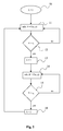
- FIG. 2 shows a flow chart that schematically describes a first preferred embodiment of the invention.
- a starting position 10 the engine is operated in a normal lean mode with ⁇ > 1.
- a function F is calculated.
- F is a function of x and y, i.e. F depends on, at least, x and y, wherein x denotes the mass flow of NO x in the exhaust gas and y denotes the current storage capacity of the NO x -adsorbing unit.
- the calculated value of F is compared with a first threshold value v 1 .
- the function F can be formulated and calculated in a number of ways.
- x i.e. the mass flow of NO x in the exhaust gas
- EGR exhaust gas recirculation
- a NO x -sensor if a NO x -sensor is used the exhaust gas concentration of NO x can be included in the calculations.
- a NO x -sensor positioned upstream the NO x -adsorbing unit together with an air intake sensor makes it possible to calculate the mass flow of NO x , but an estimation from a mathematical model based on e.g. air and fuel can also be used.
- the other main parameter y i.e. the current storage capacity of the NO x -adsorbing unit
- the other main parameter y can be calculated using various system data such as exhaust gas temperature, temperature of NO x -adsorbing unit, degree of sulphur contamination of the NO x -adsorbing unit, time elapsed since last regeneration of the NO x -adsorbing unit, and regeneration frequency, which data may be combined with engine data in the calculations.
- the exhaust gas concentration of NO x obtained from a NO x -sensor may be used.
- a calculated value may be related to a nominal, low-temperature storage capacity.
- one may include the actual or remaining storage capacity of the NO x -adsorbing unit in the calculations, i.e. one takes the amount of NO x already stored into account.
- One example on how to express the function F is to form a ratio between a first function corresponding to the mass flow of NO x in the exhaust gas and a second function corresponding to the current storage capacity of the NO x -adsorbing unit. In such a case the first and second functions could be calculated separately from each other.
- Another example on how to express F is to include a sub-parameter that itself depends on both the mass flow of NO x in the exhaust gas and the current storage capacity of the NO x -adsorbing unit. An example of such a sub-parameter is the regeneration frequency.
- the regeneration frequency as the controlling parameter it is not necessary to calculate x and y separately; instead one may provide the system with a NO x -sensor located downstream the NO x -adsorbing unit and use the signal from this sensor to control the regeneration frequency and, thus, a value of the function F.
- the threshold values that should be used depends of course on how the function F is expressed, but also on the NO x emissions, the fuel consumption trade-off and the emission legislation. Preferably, slightly different threshold values are used in steps 12 and 15 to create a hysteresis type function and avoid oscillations in the control system.
- the inventive method is capable of decreasing the fuel consumption depending on driving conditions etc.
- the general advantages of the invention may be summarized as: 1) less need for NO x -trap and DPF regeneration actions, 2) smaller amounts of NO x , CO and HC in tailpipe emissions and 3) possible decrease in fuel consumption.
- a return to lean engine operation may be initiated when the predicted NO x -emissions in a lean mode falls below a certain level.
- the method according to the invention may be applied to any internal combustion engine adapted to predominantly operate under lean conditions, such as diesel engines, running on diesel, natural gas, DME or other fuel, or Otto lean-burn engines.
Landscapes
- Engineering & Computer Science (AREA)
- Chemical & Material Sciences (AREA)
- Combustion & Propulsion (AREA)
- Mechanical Engineering (AREA)
- General Engineering & Computer Science (AREA)
- Chemical Kinetics & Catalysis (AREA)
- Exhaust Gas After Treatment (AREA)
- Exhaust-Gas Circulating Devices (AREA)
Abstract
Description
- The invention relates to a method for operating an exhaust gas purification system comprising an internal combustion engine, in particular, a diesel engine.
- Purification of exhaust gas emanating from internal combustion engines is generally a matter of converting hydrocarbons (HC), carbon monoxide (CO), nitrogen oxides (NOx) and/or particulate matter (PM) into less hazardous compounds. For engines operating at a stoichiometric air-to-fuel ratio (A) a conventional three-way catalyst is normally capable of converting HC, CO and NOx in a sufficiently efficient way. For engines operating at a high air-to-fuel ratio (A) (i.e. under lean conditions) such as Diesel engines and lean-burn Otto engines the main problem is to reduce NOx to nitrogen (N2) since HC and CO are readily oxidized in the excess of oxygen. In addition, depending on the type of engine, there may also be a need for treatment of PM.
- In order to convert NOx in engines operating at a high air-to-fuel ratio (A) so-called NOx-traps, or NOx-adsorbents, have been developed. In principle, a NOx-trap is a device comprising a catalytic material such as precious metals and a NOx-storing compound such as barium which device is capable of storing NOx during oxygen-rich, i.e. lean, conditions and reducing NOx into N2 during rich or stoichiometric conditions.
- A NOx-trap has a certain NOx storage capacity which can be expressed in e.g. gram NOx storable. When a NOx-trap is full, i.e. when no more NOx can be stored, it has to be regenerated. This is conventionally done by controlling the engine as to operate under rich conditions during a short, predetermined or sensor determined, time period, usually a number of seconds, during which time period the stored NOx is converted. The storage capacity is mainly dependent on the temperature and decreases considerably above around 450°C.
- Under normal conditions NOx-traps generally work well and are efficiently regenerated. However, NOx-traps, or exhaust gas purification systems including NOx-traps, have not yet been optimized for more special conditions, such as high-load situations with a high NOx mass flow and high exhaust temperatures.
- An object of this invention is to provide a method for operating an exhaust gas purification system that reduces the emissions of hazardous compounds in situations where the temperature of the system is high, e.g. in situations where the engine load is high. This object is achieved by the technical features contained in
claim 1. The dependent claims contain advantageous embodiments, further developments and variants of the invention. - The invention concerns a method for operating an exhaust gas purification system, said system comprising a controllable internal combustion engine adapted to predominantly operate under lean conditions, and a NOx-adsorbing unit capable of storing NOx during lean conditions and converting NOx into N2 during rich or stoichiometric conditions, said system having a capability of oxidizing HC and CO and reducing NOx under stoichiometric conditions. The invention is characterized in that the method comprises the steps of: determining a representation of a mass flow of NOx in the exhaust gas and a current storage capacity of the NOx-adsorbing unit, and switching engine operation mode between lean conditions and stoichiometric conditions depending on the representation of the NOx mass flow in the exhaust gas and the current storage capacity.
- Thus, in the first step one determines a representation of two main parameters or of a relation between two main parameters, whereas in the second step one uses the determined value or values as a basis for a decision on whether to switch engine operation mode.
- During lean operation of the engine a representation of the main parameter values, or their relation, form an indicator on whether the NOx-emissions are, or will get, inadmissibly high in the tailpipe at the present conditions, i.e. with a certain mass flow of NOx in the exhaust gas, and a certain current storage capacity of the NOx-adsorbing unit. If, for example, a ratio between the two values reach a certain limit the engine operation mode can be switched to stoichiometric conditions so that the catalytic converter can work as a three-way catalyst and thereby continuously and simultaneously reduce the amounts of NOx, HC and CO in the exhaust gas. Correspondingly, during stoichiometric operation of the engine a representation of the main parameter values, or their relation, form an indicator on whether the predicted NOx-emissions are sufficiently low for switching to the normal lean operation mode.
- An advantageous effect of the method according to the invention is that one can avoid a very frequent regeneration of the NOx-adsorbing unit that conventionally is required when the NOx mass flow is high and the temperature of the NOx-adsorbing unit is close to a maximum storage temperature, i.e. when the current storage capacity is relatively small. Frequent regeneration events lead to increased fuel penalty and increased emissions of HC and CO which thus is avoided by the method according to the invention.
- An example of a situation where the inventive method is very useful is when the engine is operated at high load which typically leads to both an increased total exhaust gas mass flow and an increased concentration of NOx in the exhaust gas flow. It also leads to an increased exhaust gas temperature which heats up the NOx-adsorbing unit and in turn reduces its NOx storage capacity.
- A diesel engine is conventionally operated in a lean combustion mode regardless of the load conditions; typically prior art diesel engines operate with an air-to-fuel ratio in the range 1.2 - 1.4 in high load situations. A diesel engine operated according to the inventive method is thus in clear contrast to such a prior art diesel engine.
- A further advantageous effect of the inventive method is that one can avoid instantaneous NOx break-through emissions, i.e. one can avoid that most or all of the NOx flows straight through the NOx-adsorbing unit, when the storage capacity of the NOx-adsorbing unit is very small or zero.
- It should be emphasized that the two main parameters, i.e. the mass flow of NOx in the exhaust gas and the current storage capacity of the NOx-adsorbing unit, do not need to be determined by direct means; they are preferably determined indirectly by calculations using a number of measured or calculated sub-parameters, such as engine data and exhaust gas temperatures and concentrations. Neither is it necessary to determine a "true" value of a certain main parameter; depending on how the method is realized it may be sufficient to determine a value that is proportional, or close to proportional, to a certain main parameter or to a function of the two parameters. Thus, it is sufficient to determine a representation of a "true" value. For instance, the current storage capacity of the NOx-adsorbing unit may be determined by measuring the temperature of the unit and, using a predefined function that describes the dependency of the storage capacity on the temperature, calculating a value in terms of storage capacity in percentage of a nominal, low-temperature storage capacity. Such a calculated value is a "determination of a representation of the current storage capacity of the NOx-adsorbing unit" with the interpretation that should be used here.
- In a first preferred embodiment of the invention the method comprises the steps of determining a value of a function F, wherein F is a function of at least the mass flow of NOx in the exhaust gas and the current storage capacity of the NOx-adsorbing unit, and comparing the value with a predetermined threshold value. Preferably, the method also comprises the step of switching engine operation mode between lean conditions and stoichiometric conditions depending on the relationship between the value of the function F and the threshold value.
- The function F may be calculated in different ways; the point is to use a function that depends on the two main parameters given above, which main parameters in turn may be determined from a number of measured or calculated sub-parameters, and let a calculated value of this function form a part of the input data used for controlling the engine.
- In the description of the invention given below reference is made to the following figure, in which:
- Figure 1
- shows, in a schematic view, an exhaust gas purification system to which the inventive method can be applied, and
- Figure 2
- shows a flow chart that schematically describes a first embodiment of the invention.
- Figure 1 shows, in a schematic view, an example of an exhaust
gas purification system 1 to which the inventive method can be applied. The system comprises a controllableinternal combustion engine 3 adapted to predominantly operate under lean conditions, such as a diesel engine; a combined NOx-adsorbing unit/catalytic converter 5 capable of storing NOx during lean conditions and converting NOx into N2 during rich or stoichiometric conditions, and with a capability of oxidizing HC and CO and reducing NOx under stoichiometric conditions; aparticulate filter 7 and acontrol unit 8. Anexhaust gas conduit 4 leads exhaust gas from theengine 3 downstream via the combined NOx-adsorbing unit/catalytic converter 5 and theparticulate filter 7 to the tailpipe 4'. Thecontrol unit 8 receives input data from the system, such as engine load, engine speed, status of exhaust gas recirculation (EGR) circuit, air intake, fuel consumption, and temperatures of the NOx-adsorbingunit 5, theparticulate filter 7 and at various positions along theexhaust conduit 4. The system may further comprise NOx and/or lambda sensors located at various positions in the system. Signals from such sensors are preferably also transmitted to thecontrol unit 8. Thecontrol unit 8 is further adapted to process selected input data, such as the air-to-fuel ratio (lambda) at a certain position in the system, and control the operation of theengine 3. This type of engine controlling is in principle well known to a person skilled in the art. It may be noted that all input data mentioned above is not required for applying the inventive method as will be further described below. - With the expression stoichiometric conditions is meant that the air-to-fuel ratio (lambda) is close to 1.0, i.e. the ratio may be a few hundredths below or above 1.
- For the inventive method to be useful it is important that the
exhaust aftertreatment system 1 has a three-way catalyst capability, i.e. that the system is capable of oxidizing HC and CO and reducing NOx under stoichiometric conditions. This capability can be arranged in a separate catalytic converter but, preferably, the NOx-adsorbingunit 5 is capable of operating as a catalytic converter as exemplified in figure 1. Most conventional NOx-traps have this capability. - The inventive method can be advantageously applied in various situations. A first example is when the temperature of the NOx-
trap 5 is relatively close to a maximum storage temperature of the NOx-trap. Typically, this example would refer to a temperature of approximately 400-450°C for conventional NOx-traps. In this situation the NOx storage capacity is reduced, i.e. the current storage capacity is low, which leads to frequent NOx regeneration events, in particular if the NOx mass flow is high. Each regeneration leads to a slip of a certain amount of NOx, HC and CO which amount increases with increasing load. Frequent regeneration leads to increased fuel penalty and increased NOx, HC and CO break-through. At some point on the regeneration frequency scale the tailpipe emissions, integrated over a certain time period, get so high that it is favourable to switch engine operation mode from the normal lean lambda (i.e. air-to-fuel ratio) strategy, which for a conventional diesel engine means that lambda is approximately 1.3, to a lambda-1 strategy, i.e. stoichiometric conditions. Since the regeneration frequency is a function of the mass flow of NOx in the exhaust gas and the current storage capacity of the NOx-adsorbing unit this point on the regeneration frequency scale can be determined from these two main parameters. By applying the inventive method to the conditions of this example the NOx emissions can be decreased because of the three-way catalyst capability and HC/CO emissions can be decreased because of fewer NOx regeneration events. - A second example is when the temperature of the NOx-
trap 5 rises above the maximum storage temperature of the NOx-trap, i.e. approximately > 450-500°C for conventional NOx-traps. In this situation most of the NOx emissions will pass through the NOx-trap. By switching over from a normal lean engine operation mode to a lambda-1 strategy a three-way catalyst function can be obtained. This has the effect that NOx-emissions will decrease due to catalytic conversion. - A third example is when the system is equipped with a diesel particulate filter (DPF) 7 and the exhaust gas has such a high temperature that the DPF reaches its soot ignition temperature, which for conventional catalytic DPFs is approximately 580°C. Also in this situation the NOx emissions will pass through the NOx trap. Again, by switching over from the normal engine operation mode, e.g. a conventional lean diesel lambda strategy of around 1.3, to a lambda-1 strategy a three-way catalyst function can be obtained. This has again the effect that NOx emissions will decrease due to catalytic conversion. In addition, the decreased content of oxygen will result in a well controlled regeneration of the DPF lowering the risk of damaging the DPF due to overheating. A further advantage of this third example is that the high temperature of the exhaust gas is utilized for regeneration of the DPF which means that the number of conventional regenerations of the DPF, i.e. regenerations where the exhaust gas temperature is actively increased by feeding additional fuel to the engine, is reduced. Thereby the fuel consumption is reduced.
- The desired value of lambda used for controlling the engine may correspond to different positions in the exhaust gas purification system. In the third example given above the lambda value referred to is preferably a value measured or calculated downstream the DPF. By using a lambda value downstream the DPF it is possible to achieve a small excess of oxygen in the exhaust gas upstream the DPF, which excess is sufficient for an efficient, but still controlled, regeneration of the DPF. This efficient and controlled regeneration of the DPF can of course also be achieved by controlling the lambda upstream the DPF to a preferred value slightly above one.
- Figure 2 shows a flow chart that schematically describes a first preferred embodiment of the invention. In a starting
position 10 the engine is operated in a normal lean mode with λ > 1. In afirst step 11 of the method a function F is calculated. F is a function of x and y, i.e. F depends on, at least, x and y, wherein x denotes the mass flow of NOx in the exhaust gas and y denotes the current storage capacity of the NOx-adsorbing unit. In anext step 12 the calculated value of F is compared with a first threshold value v 1. If F is less than v 1 step 11 is repeated; if F is greater than v 1 the engine operation mode is instep 13 switched from lean conditions to stoichiometric conditions, i.e. λ = 1.Step 14 is similar to step 11, i.e. the function F is calculated. In anext step 15 the calculated value of F is compared with a second threshold value v 2. If F is greater than v 2 step 14 is repeated; if F is less than v 2 the engine operation mode is instep 16 switched back to lean conditions, i.e. λ > 1 and step 11 can be run again. - The function F can be formulated and calculated in a number of ways. For instance, x, i.e. the mass flow of NOx in the exhaust gas, can be calculated using various engine data, such as load, air intake, fuel consumption, air-to-fuel condition, engine speed, exhaust gas recirculation (EGR) status, and engine temperature. Further, if a NOx-sensor is used the exhaust gas concentration of NOx can be included in the calculations. For instance, a NOx-sensor positioned upstream the NOx-adsorbing unit together with an air intake sensor makes it possible to calculate the mass flow of NOx, but an estimation from a mathematical model based on e.g. air and fuel can also be used.
- The other main parameter y, i.e. the current storage capacity of the NOx-adsorbing unit, can be calculated using various system data such as exhaust gas temperature, temperature of NOx-adsorbing unit, degree of sulphur contamination of the NOx-adsorbing unit, time elapsed since last regeneration of the NOx-adsorbing unit, and regeneration frequency, which data may be combined with engine data in the calculations. Also the exhaust gas concentration of NOx obtained from a NOx-sensor may be used. To obtain the current storage capacity of the NOx-adsorbing unit a calculated value may be related to a nominal, low-temperature storage capacity. In a refined controlling variant one may include the actual or remaining storage capacity of the NOx-adsorbing unit in the calculations, i.e. one takes the amount of NOx already stored into account.
- One example on how to express the function F is to form a ratio between a first function corresponding to the mass flow of NOx in the exhaust gas and a second function corresponding to the current storage capacity of the NOx-adsorbing unit. In such a case the first and second functions could be calculated separately from each other. Another example on how to express F is to include a sub-parameter that itself depends on both the mass flow of NOx in the exhaust gas and the current storage capacity of the NOx-adsorbing unit. An example of such a sub-parameter is the regeneration frequency. Using the regeneration frequency as the controlling parameter it is not necessary to calculate x and y separately; instead one may provide the system with a NOx-sensor located downstream the NOx-adsorbing unit and use the signal from this sensor to control the regeneration frequency and, thus, a value of the function F.
- The threshold values that should be used depends of course on how the function F is expressed, but also on the NOx emissions, the fuel consumption trade-off and the emission legislation. Preferably, slightly different threshold values are used in
steps - The invention has in principal the following effects on the fuel consumption: 1) a decreased air-to-fuel ratio (lambda) increases fuel consumption, 2) no additional storage of NOx during engine operation at lambda = 1 decreases the need for regenerations which in turn decreases fuel consumption, 3) less need for conventional fuel-consuming DPF regeneration actions decreases fuel consumption and 4) altered trade-off between fuel consumption and engine out NOx during engine operation at lambda = 1 decreases fuel consumption since NOx does not have to be considered when optimizing injection timing. As an overall effect the inventive method is capable of decreasing the fuel consumption depending on driving conditions etc.
- The general advantages of the invention may be summarized as: 1) less need for NOx-trap and DPF regeneration actions, 2) smaller amounts of NOx, CO and HC in tailpipe emissions and 3) possible decrease in fuel consumption.
- A return to lean engine operation may be initiated when the predicted NOx-emissions in a lean mode falls below a certain level.
- The invention is not limited by the embodiments described above but a number of modifications are possible within the scope of the claims.
- The method according to the invention may be applied to any internal combustion engine adapted to predominantly operate under lean conditions, such as diesel engines, running on diesel, natural gas, DME or other fuel, or Otto lean-burn engines.
Claims (10)
- Method for operating an exhaust gas purification system (1), said system comprising- a controllable internal combustion engine (3) adapted to predominantly operate under lean conditions, and- a NOx-adsorbing unit (5) capable of storing NOx during lean conditions and converting NOx into N2 during rich or stoichiometric conditions,characterized in
said system having a capability of oxidizing HC and CO and reducing NOx under stoichiometric conditions,
that the method comprises the steps of:- determining a representation of a mass flow of NOx in the exhaust gas and a current storage capacity of the NOx-adsorbing unit (5), and- switching engine operation mode between lean conditions and stoichiometric conditions depending on the representation of the NOx mass flow in the exhaust gas and the current storage capacity of the NOx-adsorbing unit (5). - Method according to claim 1,
characterized in
that it further comprises the steps of:- determining a value of a function F, wherein F is a function of at least the mass flow of NOx in the exhaust gas and the current storage capacity of the NOx-adsorbing unit, and- comparing the value with a predetermined threshold value. - Method according to claim 2,
characterized in
that it further comprises the step of:- switching engine operation mode between lean conditions and stoichiometric conditions depending on the relationship between the value of the function F and the threshold value. - Method according to anyone of the above claims,
characterized in
that it further comprises the step of:- monitoring the exhaust gas concentration of NOx using a NOx-sensor. - Method according to anyone of the above claims,
characterized in
that the mass flow of NOx in the exhaust gas is calculated using one or several of the following parameters: engine load, engine air-to-fuel condition, engine speed, exhaust gas recirculation (EGR) status, engine temperature and exhaust gas concentration of NOx. - Method according to anyone of the above claims,
characterized in
that the current storage capacity of the NOx-adsorbing is calculated using one or several of the following parameters: exhaust gas temperature upstream the NOx-adsorbing unit, NOx-adsorbing unit temperature, exhaust gas temperature downstream the NOx-adsorbing unit, exhaust gas concentration of NOx, degree of sulphur contamination of the NOx-adsorbing unit, time elapsed since last regeneration of the NOx-adsorbing unit, and regeneration frequency. - Method according to anyone of the above claims,
characterized in
that the NOx-adsorbing unit is capable of oxidizing HC and CO and reducing NOx under stoichiometric conditions. - Method according to anyone of the above claims,
characterized in
that it comprises the step of:- controlling the engine such that the stoichiometric conditions are achieved downstream a particulate filter positioned downstream the NOx-adsorbing unit or integrated with the NOx-adsorbing unit into a single unit. - Method according to anyone of the above claims,
characterized in
that the engine is a diesel engine. - Exhaust gas purification system comprising- a controllable internal combustion engine adapted to predominantly operate under lean conditions, and- a NOx-adsorbing unit capable of storing NOx during lean conditions and converting NOx into N2 during rich or stoichiometric conditions,characterized in
said system having a capability of oxidizing HC and CO and reducing NOx under stoichiometric conditions,
that the system is configured to be run by a method according to anyone of claims 1 to 9.
Priority Applications (3)
| Application Number | Priority Date | Filing Date | Title |
|---|---|---|---|
| DE602005006545T DE602005006545D1 (en) | 2005-06-17 | 2005-06-17 | Method for operating an exhaust gas purification system |
| AT05105379T ATE394589T1 (en) | 2005-06-17 | 2005-06-17 | METHOD FOR OPERATING AN EXHAUST GAS PURIFICATION SYSTEM |
| EP05105379A EP1734240B1 (en) | 2005-06-17 | 2005-06-17 | Method for operating an exhaust gas purification system |
Applications Claiming Priority (1)
| Application Number | Priority Date | Filing Date | Title |
|---|---|---|---|
| EP05105379A EP1734240B1 (en) | 2005-06-17 | 2005-06-17 | Method for operating an exhaust gas purification system |
Publications (2)
| Publication Number | Publication Date |
|---|---|
| EP1734240A1 true EP1734240A1 (en) | 2006-12-20 |
| EP1734240B1 EP1734240B1 (en) | 2008-05-07 |
Family
ID=35376975
Family Applications (1)
| Application Number | Title | Priority Date | Filing Date |
|---|---|---|---|
| EP05105379A Expired - Lifetime EP1734240B1 (en) | 2005-06-17 | 2005-06-17 | Method for operating an exhaust gas purification system |
Country Status (3)
| Country | Link |
|---|---|
| EP (1) | EP1734240B1 (en) |
| AT (1) | ATE394589T1 (en) |
| DE (1) | DE602005006545D1 (en) |
Cited By (2)
| Publication number | Priority date | Publication date | Assignee | Title |
|---|---|---|---|---|
| FR2927119A1 (en) * | 2008-02-04 | 2009-08-07 | Renault Sas | METHOD FOR MANAGING A DEVICE FOR AFTER-TREATMENT OF THE EXHAUST GASES OF AN ENGINE, INCLUDING A LOW FREQUENCY MODE AND A HIGH FREQUENCY MODE OF ALTERNATION OF THE STORAGE AND PURGE PHASES. |
| WO2016017154A1 (en) * | 2014-07-28 | 2016-02-04 | Toyota Jidosha Kabushiki Kaisha | Control system of internal combustion engine |
Citations (4)
| Publication number | Priority date | Publication date | Assignee | Title |
|---|---|---|---|---|
| US20030093988A1 (en) * | 2001-11-19 | 2003-05-22 | Gopichandra Surnilla | Nox trap efficiency |
| US20040031261A1 (en) * | 2002-08-13 | 2004-02-19 | Jing Sun | System and method for lean NOx trap control and diagnosis |
| DE10241499A1 (en) * | 2002-09-07 | 2004-03-18 | Audi Ag | Method for determining the degree of aging of a nitrogen oxide storage catalytic converter of an internal combustion engine, in particular a motor vehicle |
| DE10318116A1 (en) * | 2003-04-22 | 2004-11-11 | Robert Bosch Gmbh | Method for operating an internal combustion engine, in particular a motor vehicle |
-
2005
- 2005-06-17 AT AT05105379T patent/ATE394589T1/en not_active IP Right Cessation
- 2005-06-17 EP EP05105379A patent/EP1734240B1/en not_active Expired - Lifetime
- 2005-06-17 DE DE602005006545T patent/DE602005006545D1/en not_active Expired - Lifetime
Patent Citations (4)
| Publication number | Priority date | Publication date | Assignee | Title |
|---|---|---|---|---|
| US20030093988A1 (en) * | 2001-11-19 | 2003-05-22 | Gopichandra Surnilla | Nox trap efficiency |
| US20040031261A1 (en) * | 2002-08-13 | 2004-02-19 | Jing Sun | System and method for lean NOx trap control and diagnosis |
| DE10241499A1 (en) * | 2002-09-07 | 2004-03-18 | Audi Ag | Method for determining the degree of aging of a nitrogen oxide storage catalytic converter of an internal combustion engine, in particular a motor vehicle |
| DE10318116A1 (en) * | 2003-04-22 | 2004-11-11 | Robert Bosch Gmbh | Method for operating an internal combustion engine, in particular a motor vehicle |
Cited By (5)
| Publication number | Priority date | Publication date | Assignee | Title |
|---|---|---|---|---|
| FR2927119A1 (en) * | 2008-02-04 | 2009-08-07 | Renault Sas | METHOD FOR MANAGING A DEVICE FOR AFTER-TREATMENT OF THE EXHAUST GASES OF AN ENGINE, INCLUDING A LOW FREQUENCY MODE AND A HIGH FREQUENCY MODE OF ALTERNATION OF THE STORAGE AND PURGE PHASES. |
| WO2009098419A3 (en) * | 2008-02-04 | 2009-10-01 | Renault S.A.S | Method of managing a device for the post-treatment of exhaust gases from an engine, including a low-frequency mode and a high-frequency mode of alternating the storage and purge phases |
| WO2016017154A1 (en) * | 2014-07-28 | 2016-02-04 | Toyota Jidosha Kabushiki Kaisha | Control system of internal combustion engine |
| CN106574565A (en) * | 2014-07-28 | 2017-04-19 | 丰田自动车株式会社 | Control system of internal combustion engine |
| CN106574565B (en) * | 2014-07-28 | 2019-10-18 | 丰田自动车株式会社 | Internal combustion engine control system |
Also Published As
| Publication number | Publication date |
|---|---|
| ATE394589T1 (en) | 2008-05-15 |
| DE602005006545D1 (en) | 2008-06-19 |
| EP1734240B1 (en) | 2008-05-07 |
Similar Documents
| Publication | Publication Date | Title |
|---|---|---|
| US7104051B2 (en) | Exhaust gas purification device | |
| US6370868B1 (en) | Method and system for purge cycle management of a lean NOx trap | |
| JP5738249B2 (en) | Exhaust gas purification system for internal combustion engine | |
| US6823843B1 (en) | System and method to minimize the amount of NOx released from a NOx trap | |
| US7073324B2 (en) | Device and method for determining the need for regeneration in a NOx storage catalyst | |
| EP1515017B1 (en) | Catalyst control apparatus of internal combustion engine | |
| US7827783B2 (en) | Exhaust gas purifying apparatus for internal combustion engine | |
| US7946108B2 (en) | Method for regenerating a nitrogen oxide storage catalytic converter | |
| US10443525B2 (en) | Exhaust emission control system of engine | |
| JP2010127251A (en) | Exhaust gas purifier for internal combustion engine | |
| EP1469180B1 (en) | Method for managing NOx catalyst | |
| US8028518B2 (en) | Sulfur purge control device for an internal combustion engine | |
| EP1510679B1 (en) | Excessive sulfur poisoning recovery control method and apparatus for exhaust gas control catalyst | |
| US20220186643A1 (en) | Exhaust purification system of internal combustion engine | |
| EP1734240B1 (en) | Method for operating an exhaust gas purification system | |
| US9708994B2 (en) | Method of regenerating an exhaust after treatment device | |
| JP3888115B2 (en) | Control device for internal combustion engine | |
| EP1887202B1 (en) | Sulfur purge control device for an internal combustion engine | |
| JP6244626B2 (en) | Diesel engine exhaust aftertreatment system | |
| US11808226B2 (en) | Method, processing unit, and computer program for operating an exhaust gas system | |
| JP4344729B2 (en) | Control device for internal combustion engine | |
| JP2002317682A (en) | Control device for internal combustion engine | |
| JP2014125976A (en) | Exhaust post-treatment device of diesel engine | |
| JP2007278246A (en) | Exhaust gas purification device for internal combustion engine |
Legal Events
| Date | Code | Title | Description |
|---|---|---|---|
| PUAI | Public reference made under article 153(3) epc to a published international application that has entered the european phase |
Free format text: ORIGINAL CODE: 0009012 |
|
| AK | Designated contracting states |
Kind code of ref document: A1 Designated state(s): AT BE BG CH CY CZ DE DK EE ES FI FR GB GR HU IE IS IT LI LT LU MC NL PL PT RO SE SI SK TR |
|
| AX | Request for extension of the european patent |
Extension state: AL BA HR LV MK YU |
|
| 17P | Request for examination filed |
Effective date: 20070516 |
|
| AKX | Designation fees paid |
Designated state(s): AT BE BG CH CY CZ DE DK EE ES FI FR GB GR HU IE IS IT LI LT LU MC NL PL PT RO SE SI SK TR |
|
| GRAP | Despatch of communication of intention to grant a patent |
Free format text: ORIGINAL CODE: EPIDOSNIGR1 |
|
| GRAS | Grant fee paid |
Free format text: ORIGINAL CODE: EPIDOSNIGR3 |
|
| GRAA | (expected) grant |
Free format text: ORIGINAL CODE: 0009210 |
|
| AK | Designated contracting states |
Kind code of ref document: B1 Designated state(s): AT BE BG CH CY CZ DE DK EE ES FI FR GB GR HU IE IS IT LI LT LU MC NL PL PT RO SE SI SK TR |
|
| REG | Reference to a national code |
Ref country code: GB Ref legal event code: FG4D |
|
| REG | Reference to a national code |
Ref country code: CH Ref legal event code: EP |
|
| REG | Reference to a national code |
Ref country code: IE Ref legal event code: FG4D Free format text: LANGUAGE OF EP DOCUMENT: FRENCH |
|
| REF | Corresponds to: |
Ref document number: 602005006545 Country of ref document: DE Date of ref document: 20080619 Kind code of ref document: P |
|
| REG | Reference to a national code |
Ref country code: SE Ref legal event code: TRGR |
|
| PG25 | Lapsed in a contracting state [announced via postgrant information from national office to epo] |
Ref country code: SI Free format text: LAPSE BECAUSE OF FAILURE TO SUBMIT A TRANSLATION OF THE DESCRIPTION OR TO PAY THE FEE WITHIN THE PRESCRIBED TIME-LIMIT Effective date: 20080507 |
|
| PG25 | Lapsed in a contracting state [announced via postgrant information from national office to epo] |
Ref country code: NL Free format text: LAPSE BECAUSE OF FAILURE TO SUBMIT A TRANSLATION OF THE DESCRIPTION OR TO PAY THE FEE WITHIN THE PRESCRIBED TIME-LIMIT Effective date: 20080507 Ref country code: FI Free format text: LAPSE BECAUSE OF FAILURE TO SUBMIT A TRANSLATION OF THE DESCRIPTION OR TO PAY THE FEE WITHIN THE PRESCRIBED TIME-LIMIT Effective date: 20080507 Ref country code: ES Free format text: LAPSE BECAUSE OF FAILURE TO SUBMIT A TRANSLATION OF THE DESCRIPTION OR TO PAY THE FEE WITHIN THE PRESCRIBED TIME-LIMIT Effective date: 20080818 |
|
| NLV1 | Nl: lapsed or annulled due to failure to fulfill the requirements of art. 29p and 29m of the patents act | ||
| PG25 | Lapsed in a contracting state [announced via postgrant information from national office to epo] |
Ref country code: PL Free format text: LAPSE BECAUSE OF FAILURE TO SUBMIT A TRANSLATION OF THE DESCRIPTION OR TO PAY THE FEE WITHIN THE PRESCRIBED TIME-LIMIT Effective date: 20080507 Ref country code: AT Free format text: LAPSE BECAUSE OF FAILURE TO SUBMIT A TRANSLATION OF THE DESCRIPTION OR TO PAY THE FEE WITHIN THE PRESCRIBED TIME-LIMIT Effective date: 20080507 |
|
| PG25 | Lapsed in a contracting state [announced via postgrant information from national office to epo] |
Ref country code: IS Free format text: LAPSE BECAUSE OF FAILURE TO SUBMIT A TRANSLATION OF THE DESCRIPTION OR TO PAY THE FEE WITHIN THE PRESCRIBED TIME-LIMIT Effective date: 20080907 |
|
| PG25 | Lapsed in a contracting state [announced via postgrant information from national office to epo] |
Ref country code: LT Free format text: LAPSE BECAUSE OF FAILURE TO SUBMIT A TRANSLATION OF THE DESCRIPTION OR TO PAY THE FEE WITHIN THE PRESCRIBED TIME-LIMIT Effective date: 20080507 Ref country code: MC Free format text: LAPSE BECAUSE OF NON-PAYMENT OF DUE FEES Effective date: 20080630 Ref country code: CZ Free format text: LAPSE BECAUSE OF FAILURE TO SUBMIT A TRANSLATION OF THE DESCRIPTION OR TO PAY THE FEE WITHIN THE PRESCRIBED TIME-LIMIT Effective date: 20080507 Ref country code: DK Free format text: LAPSE BECAUSE OF FAILURE TO SUBMIT A TRANSLATION OF THE DESCRIPTION OR TO PAY THE FEE WITHIN THE PRESCRIBED TIME-LIMIT Effective date: 20080507 |
|
| PG25 | Lapsed in a contracting state [announced via postgrant information from national office to epo] |
Ref country code: RO Free format text: LAPSE BECAUSE OF FAILURE TO SUBMIT A TRANSLATION OF THE DESCRIPTION OR TO PAY THE FEE WITHIN THE PRESCRIBED TIME-LIMIT Effective date: 20080507 Ref country code: BE Free format text: LAPSE BECAUSE OF FAILURE TO SUBMIT A TRANSLATION OF THE DESCRIPTION OR TO PAY THE FEE WITHIN THE PRESCRIBED TIME-LIMIT Effective date: 20080507 Ref country code: PT Free format text: LAPSE BECAUSE OF FAILURE TO SUBMIT A TRANSLATION OF THE DESCRIPTION OR TO PAY THE FEE WITHIN THE PRESCRIBED TIME-LIMIT Effective date: 20081007 Ref country code: SK Free format text: LAPSE BECAUSE OF FAILURE TO SUBMIT A TRANSLATION OF THE DESCRIPTION OR TO PAY THE FEE WITHIN THE PRESCRIBED TIME-LIMIT Effective date: 20080507 |
|
| PLBE | No opposition filed within time limit |
Free format text: ORIGINAL CODE: 0009261 |
|
| STAA | Information on the status of an ep patent application or granted ep patent |
Free format text: STATUS: NO OPPOSITION FILED WITHIN TIME LIMIT |
|
| 26N | No opposition filed |
Effective date: 20090210 |
|
| PG25 | Lapsed in a contracting state [announced via postgrant information from national office to epo] |
Ref country code: IE Free format text: LAPSE BECAUSE OF NON-PAYMENT OF DUE FEES Effective date: 20080617 Ref country code: EE Free format text: LAPSE BECAUSE OF FAILURE TO SUBMIT A TRANSLATION OF THE DESCRIPTION OR TO PAY THE FEE WITHIN THE PRESCRIBED TIME-LIMIT Effective date: 20080507 Ref country code: BG Free format text: LAPSE BECAUSE OF FAILURE TO SUBMIT A TRANSLATION OF THE DESCRIPTION OR TO PAY THE FEE WITHIN THE PRESCRIBED TIME-LIMIT Effective date: 20080807 |
|
| PG25 | Lapsed in a contracting state [announced via postgrant information from national office to epo] |
Ref country code: IT Free format text: LAPSE BECAUSE OF FAILURE TO SUBMIT A TRANSLATION OF THE DESCRIPTION OR TO PAY THE FEE WITHIN THE PRESCRIBED TIME-LIMIT Effective date: 20080507 |
|
| REG | Reference to a national code |
Ref country code: CH Ref legal event code: PL |
|
| PG25 | Lapsed in a contracting state [announced via postgrant information from national office to epo] |
Ref country code: CH Free format text: LAPSE BECAUSE OF NON-PAYMENT OF DUE FEES Effective date: 20090630 Ref country code: LI Free format text: LAPSE BECAUSE OF NON-PAYMENT OF DUE FEES Effective date: 20090630 |
|
| PG25 | Lapsed in a contracting state [announced via postgrant information from national office to epo] |
Ref country code: LU Free format text: LAPSE BECAUSE OF NON-PAYMENT OF DUE FEES Effective date: 20080617 Ref country code: HU Free format text: LAPSE BECAUSE OF FAILURE TO SUBMIT A TRANSLATION OF THE DESCRIPTION OR TO PAY THE FEE WITHIN THE PRESCRIBED TIME-LIMIT Effective date: 20081108 Ref country code: CY Free format text: LAPSE BECAUSE OF FAILURE TO SUBMIT A TRANSLATION OF THE DESCRIPTION OR TO PAY THE FEE WITHIN THE PRESCRIBED TIME-LIMIT Effective date: 20080507 |
|
| PG25 | Lapsed in a contracting state [announced via postgrant information from national office to epo] |
Ref country code: TR Free format text: LAPSE BECAUSE OF FAILURE TO SUBMIT A TRANSLATION OF THE DESCRIPTION OR TO PAY THE FEE WITHIN THE PRESCRIBED TIME-LIMIT Effective date: 20080507 |
|
| PG25 | Lapsed in a contracting state [announced via postgrant information from national office to epo] |
Ref country code: GR Free format text: LAPSE BECAUSE OF FAILURE TO SUBMIT A TRANSLATION OF THE DESCRIPTION OR TO PAY THE FEE WITHIN THE PRESCRIBED TIME-LIMIT Effective date: 20080808 |
|
| REG | Reference to a national code |
Ref country code: FR Ref legal event code: ST Effective date: 20110729 |
|
| PG25 | Lapsed in a contracting state [announced via postgrant information from national office to epo] |
Ref country code: FR Free format text: LAPSE BECAUSE OF NON-PAYMENT OF DUE FEES Effective date: 20080707 |
|
| REG | Reference to a national code |
Ref country code: GB Ref legal event code: 732E Free format text: REGISTERED BETWEEN 20111020 AND 20111025 |
|
| REG | Reference to a national code |
Ref country code: DE Ref legal event code: R082 Ref document number: 602005006545 Country of ref document: DE Representative=s name: VOSSIUS & PARTNER, DE |
|
| REG | Reference to a national code |
Ref country code: DE Ref legal event code: R081 Ref document number: 602005006545 Country of ref document: DE Owner name: VOLVO CAR CORPORATION, SE Free format text: FORMER OWNER: FORD GLOBAL TECHNOLOGIES, LLC, DEARBORN, MICH., US Effective date: 20120207 Ref country code: DE Ref legal event code: R082 Ref document number: 602005006545 Country of ref document: DE Representative=s name: VOSSIUS & PARTNER PATENTANWAELTE RECHTSANWAELT, DE Effective date: 20120207 |
|
| PGFP | Annual fee paid to national office [announced via postgrant information from national office to epo] |
Ref country code: GB Payment date: 20140619 Year of fee payment: 10 |
|
| PGFP | Annual fee paid to national office [announced via postgrant information from national office to epo] |
Ref country code: SE Payment date: 20140627 Year of fee payment: 10 |
|
| REG | Reference to a national code |
Ref country code: SE Ref legal event code: EUG |
|
| GBPC | Gb: european patent ceased through non-payment of renewal fee |
Effective date: 20150617 |
|
| PG25 | Lapsed in a contracting state [announced via postgrant information from national office to epo] |
Ref country code: SE Free format text: LAPSE BECAUSE OF NON-PAYMENT OF DUE FEES Effective date: 20150618 |
|
| PG25 | Lapsed in a contracting state [announced via postgrant information from national office to epo] |
Ref country code: GB Free format text: LAPSE BECAUSE OF NON-PAYMENT OF DUE FEES Effective date: 20150617 |
|
| PGFP | Annual fee paid to national office [announced via postgrant information from national office to epo] |
Ref country code: DE Payment date: 20220518 Year of fee payment: 18 |
|
| REG | Reference to a national code |
Ref country code: DE Ref legal event code: R119 Ref document number: 602005006545 Country of ref document: DE |
|
| PG25 | Lapsed in a contracting state [announced via postgrant information from national office to epo] |
Ref country code: DE Free format text: LAPSE BECAUSE OF NON-PAYMENT OF DUE FEES Effective date: 20240103 |