EP1733928A2 - Vehicle passenger detection apparatus with wireless acquisition of passenger-related data - Google Patents
Vehicle passenger detection apparatus with wireless acquisition of passenger-related data Download PDFInfo
- Publication number
- EP1733928A2 EP1733928A2 EP06076152A EP06076152A EP1733928A2 EP 1733928 A2 EP1733928 A2 EP 1733928A2 EP 06076152 A EP06076152 A EP 06076152A EP 06076152 A EP06076152 A EP 06076152A EP 1733928 A2 EP1733928 A2 EP 1733928A2
- Authority
- EP
- European Patent Office
- Prior art keywords
- seat
- passive
- acoustic wave
- surface acoustic
- seating
- Prior art date
- Legal status (The legal status is an assumption and is not a legal conclusion. Google has not performed a legal analysis and makes no representation as to the accuracy of the status listed.)
- Withdrawn
Links
- 238000001514 detection method Methods 0.000 title abstract description 10
- 238000010897 surface acoustic wave method Methods 0.000 claims abstract description 35
- 239000012530 fluid Substances 0.000 claims abstract description 22
- 239000008188 pellet Substances 0.000 claims abstract description 3
- 230000004069 differentiation Effects 0.000 abstract description 2
- 238000010586 diagram Methods 0.000 description 4
- 239000000758 substrate Substances 0.000 description 3
- 239000004020 conductor Substances 0.000 description 2
- 239000013078 crystal Substances 0.000 description 2
- 238000005516 engineering process Methods 0.000 description 1
- 239000006260 foam Substances 0.000 description 1
- 230000008014 freezing Effects 0.000 description 1
- 238000007710 freezing Methods 0.000 description 1
- 238000009434 installation Methods 0.000 description 1
- 238000004519 manufacturing process Methods 0.000 description 1
- 239000000463 material Substances 0.000 description 1
- 238000012986 modification Methods 0.000 description 1
- 230000004048 modification Effects 0.000 description 1
- 230000009972 noncorrosive effect Effects 0.000 description 1
- 229920001296 polysiloxane Polymers 0.000 description 1
Images

Classifications
-
- B—PERFORMING OPERATIONS; TRANSPORTING
- B60—VEHICLES IN GENERAL
- B60W—CONJOINT CONTROL OF VEHICLE SUB-UNITS OF DIFFERENT TYPE OR DIFFERENT FUNCTION; CONTROL SYSTEMS SPECIALLY ADAPTED FOR HYBRID VEHICLES; ROAD VEHICLE DRIVE CONTROL SYSTEMS FOR PURPOSES NOT RELATED TO THE CONTROL OF A PARTICULAR SUB-UNIT
- B60W40/00—Estimation or calculation of non-directly measurable driving parameters for road vehicle drive control systems not related to the control of a particular sub unit, e.g. by using mathematical models
- B60W40/08—Estimation or calculation of non-directly measurable driving parameters for road vehicle drive control systems not related to the control of a particular sub unit, e.g. by using mathematical models related to drivers or passengers
-
- B—PERFORMING OPERATIONS; TRANSPORTING
- B60—VEHICLES IN GENERAL
- B60R—VEHICLES, VEHICLE FITTINGS, OR VEHICLE PARTS, NOT OTHERWISE PROVIDED FOR
- B60R21/00—Arrangements or fittings on vehicles for protecting or preventing injuries to occupants or pedestrians in case of accidents or other traffic risks
- B60R21/01—Electrical circuits for triggering passive safety arrangements, e.g. airbags, safety belt tighteners, in case of vehicle accidents or impending vehicle accidents
- B60R21/015—Electrical circuits for triggering passive safety arrangements, e.g. airbags, safety belt tighteners, in case of vehicle accidents or impending vehicle accidents including means for detecting the presence or position of passengers, passenger seats or child seats, and the related safety parameters therefor, e.g. speed or timing of airbag inflation in relation to occupant position or seat belt use
- B60R21/01512—Passenger detection systems
- B60R21/01516—Passenger detection systems using force or pressure sensing means
- B60R21/01526—Passenger detection systems using force or pressure sensing means using piezoelectric elements
-
- B—PERFORMING OPERATIONS; TRANSPORTING
- B60—VEHICLES IN GENERAL
- B60R—VEHICLES, VEHICLE FITTINGS, OR VEHICLE PARTS, NOT OTHERWISE PROVIDED FOR
- B60R21/00—Arrangements or fittings on vehicles for protecting or preventing injuries to occupants or pedestrians in case of accidents or other traffic risks
- B60R21/01—Electrical circuits for triggering passive safety arrangements, e.g. airbags, safety belt tighteners, in case of vehicle accidents or impending vehicle accidents
- B60R2021/0104—Communication circuits for data transmission
- B60R2021/01081—Transmission medium
- B60R2021/01088—Transmission medium wireless
Definitions
- the present invention relates to detecting the presence passengers in a motor vehicle passenger compartment, and more particularly to a low-cost detection apparatus utilizing wireless acquisition of passenger-related data.
- the present invention is directed to an improved vehicle passenger presence detection apparatus including passive RF seat force sensors at each seating location and a single-point electronic control unit (ECU) for wirelessly acquiring passenger-related data from each of the sensors.
- a sensor-loaded surface acoustic wave (SAW) device is installed in each seating location of the vehicle, and the ECU wirelessly interrogates the SAW devices to determine passenger presence for each of the seating locations.
- the SAW devices have distinguishable fundamental resonance frequencies for differentiation among the seating locations.
- a fluid-filled elastomeric bladder is installed in the seat bottom of each seating location, and a pelletized sensor including a capacitive pressure sensor and a SAW device is disposed in each bladder.
- Each pressure sensor capacitively loads the respective SAW device so that when interrogated by the ECU, the SAW device emits an RF response indicative of the fluid pressure in the respective bladder, and hence, the passenger seat force.
- the ECU also wirelessly communicates with car seat RFID tags to identify the presence and location of a car seat.
- the apparatus is inherently low in cost, as the sensors are inexpensive and passive, and no wiring is required between the sensors and the ECU.
- the present invention is illustrated in the context of a vehicle passenger compartment 10 having a driver seat 12 and four passenger seats 14a, 14b, 14c and 14d.
- the passenger detection apparatus of the present invention is applied to each of the passenger seats 14a-14d.
- Each of the passenger seats 14a, 14b, 14,c, 14d is equipped with a fluid-filled elastomeric seat bladder 16a, 16b, 16c, 16d and a passive RF sensor 18a, 18b, 18c, 18d.
- each seat 14a-14d is supported on a frame 20, and includes foam cushions 22 and 24 on the seat bottom and back.
- the bladder 16a is disposed in or under the seat bottom cushion 22 substantially parallel with the seating surface, and preferably contains a fluid such as silicone which is non-corrosive, and not subject to freezing at extreme ambient temperatures.
- each passive RF sensor 18a-18b is disposed within its respective seat bladder 16a-16d.
- the fluid pressure in each seat bladder 16a-16d varies in relation to the force applied to the seating surface of the respective seat 14a-14d by an occupant, and each passive RF sensor 18a-18d is responsive to the fluid pressure in which it is disposed.
- the occupant is typically a normally seated person, but may alternately be an infant or child car seat 26 as depicted in FIG. 1B.
- the car seat 26 is equipped with a RFID tag device 28 as shown to facilitate its detection within the passenger compartment 10.
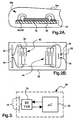
- the passive RF sensor 18a includes a capacitive pressure sensor 32 and a surface acoustic wave (SAW) device 34 mounted on a substrate 36. Since the sensor 18a is immersed in the fluid of bladder 16a, it may be encapsulated in the form of a pellet or the like so that the components 32, 34 and substrate 36 do not contact the bladder fluid.
- the pressure sensor 32 is a passive device responsive to the fluid pressure in bladder 16a, and exhibits a characteristic capacitance across its terminals 38, 40 that varies in relation to the fluid pressure, and hence, the occupant-related force applied to the seating surface of seat 14a.
- a suitable capacitive pressure sensor for this purpose is described, for example, in the U.S. Patent No.
- the SAW device 34 is a piezoelectric crystal imprinted with first and second spaced transducers 42 and 44.
- Each of the transducers 42, 44 has a pair of parallel linear terminals; a set of spaced conductor lines extend from each terminal toward the other terminal, and the conductor lines are interdigitated as indicated in FIG. 2B.
- the terminals of the first transducer 42 are connected to a set of antenna elements 46, 48 formed on the substrate 36, while the terminals of the second transducer 44 are connected to the terminals 38, 40 of capacitive pressure sensor 32.
- Communications to and from the SAW device 34 occur via antenna elements 46, 48 and the first transducer 42, while the capacitive impedance of the pressure sensor 32 variably loads the second transducer 44 in relation to the fluid pressure in bladder 16a.
- the first transducer 42 is tuned to resonate at characteristic fundamental RF frequency, and when excited by an RF interrogation signal, creates a surface acoustic wave in the piezoelectric crystal material of the SAW device 34. The surface acoustic wave propagates along the length of the SAW device 34 to the second transducer 44, and is then reflected back the first transducer 42.
- the frequency of the reflected surface acoustic wave differs from the fundamental frequency of the incident wave due to the capacitive loading of transducer 44 by the pressure sensor 32.
- the first transducer 42 converts the reflected surface acoustic wave to a corresponding RF electrical signal and the antenna elements 46, 48 transmit the RF signal as a response to the interrogation signal.
- the frequency shift of the RF response relative to the characteristic fundamental frequency of the SAW device 34 provides a measure of the fluid pressure in the respective seat bladder 16a-16d.
- the final component of the passenger detection apparatus of this invention is an electronic control unit (ECU) 50 that is disposed in a central location in the passenger compartment 10, such as in a console between the seats 12 and 14a, or in a ceiling or dome lamp assembly of the compartment 10.
- ECU 50 emits RF interrogation signals to the various passive sensors 18a-18d, and receives their RF responses.
- the ECU 50 achieves this functionality with a micro-computer 52, a RF transceiver 54 and an antenna 56.
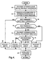
- Block 60 activates RF transceiver 54 to transmit an interrogation signal to a selected seat location (seat location N).
- the block 62 demodulates the response received by transceiver 54 (a frequency shift) and converts the result to a corresponding seat pressure for the selected seat location.
- the blocks 64 and 66 set the status for seat location N to EMPTY if the seat pressure is less than an empty seat pressure threshold. If the seat pressure exceeds the empty seat pressure threshold, the block 70 compares the seat pressure to a minimum adult pressure threshold. If the seat pressure is less than the minimum adult pressure threshold, the block 72 sets the status for seat location N to CHILD.
- the block 74 activates RF transceiver 54 to transmit an interrogation signal to the car seat RFID tag 28. If a response is received (indicating the presence of car seat 26), the blocks 76 and 78 set the status for seat location N to CAR SEAT. If no RFID response is received, the block 80 sets the status for seat location N to ADULT.
- a car seat 26 can be distinguished from a normally seated adult occupant through some other means; for example, one or more of the seat bladders 18a-18d may be configured to be provide an indication of the seat force distribution, or the dynamic variation of seat force during movement of the vehicle may be monitored and compared to patterns characteristic of the two occupant categories. In any event, once the status for seat location N has been determined, the block 82 indexes the selected seat location and the above-described steps are repeated for another seating location, as indicated.
- the present invention provides a reliable and easily installed apparatus for detecting the presence of occupants in a vehicle passenger compartment, and for identifying the presence and location of an infant or child car seat as well.
- the apparatus is inherently low in cost, as the sensors are inexpensive and passive, and no wiring is required between the sensors and the single-point ECU 50. While the invention has been described with respect to the illustrated embodiments, it is recognized that numerous modifications and variations in addition to those mentioned herein will occur to those skilled in the art.
- the interrogation signal issued by ECU 50 can alternately be a global interrogation signal that induces resonance in the SAW device of each sensor 18a-18d; in such an embodiment, the ECU 50 receives the various responses and sorts them by frequency band in order to associate each received response with a corresponding seating location.
- various system parameters such as the number of monitored seating locations and the placement of ECU 50 may also be different than shown.
- the passenger presence information obtained by ECU 50 can be used for purposes other than or in addition to scheduling deployment of restraint devices. Accordingly, it is intended that the invention not be limited to the disclosed embodiment, but that it have the full scope permitted by the language of the following claims.
Landscapes
- Engineering & Computer Science (AREA)
- Mechanical Engineering (AREA)
- Physics & Mathematics (AREA)
- Automation & Control Theory (AREA)
- Mathematical Physics (AREA)
- Transportation (AREA)
- Seats For Vehicles (AREA)
- Air Bags (AREA)
- Arrangements For Transmission Of Measured Signals (AREA)
Abstract
Description
- The present invention relates to detecting the presence passengers in a motor vehicle passenger compartment, and more particularly to a low-cost detection apparatus utilizing wireless acquisition of passenger-related data.
- Systems for detecting passenger presence in a motor vehicle are useful for determining if pyrotechnically deployed restraints such as air bags should be deployed in the event of sufficiently severe crash. Early systems focused primarily on the front passenger, but there is an increasing need to detect the presence of any passenger to ensure that various restraint devices of the vehicle are appropriately deployed. At the same time, there is great interest in minimizing the cost of the detection apparatus. Various systems and sensing technologies have been proposed for detecting passenger presence, but high system and installation costs have slowed their production usage. Accordingly, what is needed is a low-cost, easily installed passenger detection apparatus.
- The present invention is directed to an improved vehicle passenger presence detection apparatus including passive RF seat force sensors at each seating location and a single-point electronic control unit (ECU) for wirelessly acquiring passenger-related data from each of the sensors. According to the invention, a sensor-loaded surface acoustic wave (SAW) device is installed in each seating location of the vehicle, and the ECU wirelessly interrogates the SAW devices to determine passenger presence for each of the seating locations. The SAW devices have distinguishable fundamental resonance frequencies for differentiation among the seating locations.
- In a preferred embodiment, a fluid-filled elastomeric bladder is installed in the seat bottom of each seating location, and a pelletized sensor including a capacitive pressure sensor and a SAW device is disposed in each bladder. Each pressure sensor capacitively loads the respective SAW device so that when interrogated by the ECU, the SAW device emits an RF response indicative of the fluid pressure in the respective bladder, and hence, the passenger seat force. The ECU also wirelessly communicates with car seat RFID tags to identify the presence and location of a car seat. The apparatus is inherently low in cost, as the sensors are inexpensive and passive, and no wiring is required between the sensors and the ECU.
-
- FIG. 1A is an overhead diagram of a vehicle passenger compartment with multiple passenger seating locations and a wireless passenger detection apparatus according to this invention, including passive seat sensors and a centrally located electronic control unit (ECU);
- FIG. 1B depicts the ECU and a passive seat sensor installed in a vehicle seat, plus an infant or child car seat disposed on the vehicle seat;
- FIGS. 2A and 2B depict a passive seat sensor of FIGS. 1A-1B. FIG. 2A is a sectional view of the sensor and seat bladder, and FIG. 2B is a top view of the sensor;
- FIG. 3 is a block diagram of the ECU of FIG. 1; and
- FIG. 4 is a flow diagram representative of a software routine executed by the ECU of FIG. 1 according to this invention.
- Referring to FIG. 1A, the present invention is illustrated in the context of a
vehicle passenger compartment 10 having adriver seat 12 and fourpassenger seats passenger seats 14a-14d. Each of thepassenger seats elastomeric seat bladder passive RF sensor seat 14a in FIG. 1B, eachseat 14a-14d is supported on aframe 20, and includesfoam cushions bladder 16a is disposed in or under theseat bottom cushion 22 substantially parallel with the seating surface, and preferably contains a fluid such as silicone which is non-corrosive, and not subject to freezing at extreme ambient temperatures. - As illustrated with respect to
passenger seat 14a in FIGS. 1B and 2A, eachpassive RF sensor 18a-18b is disposed within itsrespective seat bladder 16a-16d. The fluid pressure in eachseat bladder 16a-16d varies in relation to the force applied to the seating surface of therespective seat 14a-14d by an occupant, and eachpassive RF sensor 18a-18d is responsive to the fluid pressure in which it is disposed. The occupant is typically a normally seated person, but may alternately be an infant orchild car seat 26 as depicted in FIG. 1B. In the illustrated embodiment, thecar seat 26 is equipped with aRFID tag device 28 as shown to facilitate its detection within thepassenger compartment 10. - Referring to FIGS. 2A-2B, the
passive RF sensor 18a includes acapacitive pressure sensor 32 and a surface acoustic wave (SAW)device 34 mounted on asubstrate 36. Since thesensor 18a is immersed in the fluid ofbladder 16a, it may be encapsulated in the form of a pellet or the like so that thecomponents substrate 36 do not contact the bladder fluid. Thepressure sensor 32 is a passive device responsive to the fluid pressure inbladder 16a, and exhibits a characteristic capacitance across itsterminals seat 14a. A suitable capacitive pressure sensor for this purpose is described, for example, in theU.S. Patent No. 5,706,565, issued on January 13, 1998 , and incorporated by reference herein. TheSAW device 34 is a piezoelectric crystal imprinted with first and second spacedtransducers transducers first transducer 42 are connected to a set ofantenna elements substrate 36, while the terminals of thesecond transducer 44 are connected to theterminals capacitive pressure sensor 32. Communications to and from theSAW device 34 occur viaantenna elements first transducer 42, while the capacitive impedance of thepressure sensor 32 variably loads thesecond transducer 44 in relation to the fluid pressure inbladder 16a. Thefirst transducer 42 is tuned to resonate at characteristic fundamental RF frequency, and when excited by an RF interrogation signal, creates a surface acoustic wave in the piezoelectric crystal material of theSAW device 34. The surface acoustic wave propagates along the length of theSAW device 34 to thesecond transducer 44, and is then reflected back thefirst transducer 42. The frequency of the reflected surface acoustic wave differs from the fundamental frequency of the incident wave due to the capacitive loading oftransducer 44 by thepressure sensor 32. Thefirst transducer 42 converts the reflected surface acoustic wave to a corresponding RF electrical signal and theantenna elements SAW device 34 provides a measure of the fluid pressure in therespective seat bladder 16a-16d. - The final component of the passenger detection apparatus of this invention is an electronic control unit (ECU) 50 that is disposed in a central location in the
passenger compartment 10, such as in a console between theseats compartment 10. As indicated by the arrows adjacent theECU 50 in FIGS. 1A and 1B, theECU 50 emits RF interrogation signals to the variouspassive sensors 18a-18d, and receives their RF responses. Referring to FIG. 3, the ECU 50 achieves this functionality with a micro-computer 52, aRF transceiver 54 and anantenna 56. - The flow diagram of FIG. 4 depicts software routine executed by the micro-computer 52 of
ECU 50 according to a preferred embodiment of this invention.Block 60 activatesRF transceiver 54 to transmit an interrogation signal to a selected seat location (seat location N). Theblock 62 demodulates the response received by transceiver 54 (a frequency shift) and converts the result to a corresponding seat pressure for the selected seat location. Theblocks block 70 compares the seat pressure to a minimum adult pressure threshold. If the seat pressure is less than the minimum adult pressure threshold, theblock 72 sets the status for seat location N to CHILD. If the seat pressure exceeds the minimum adult pressure threshold, theblock 74activates RF transceiver 54 to transmit an interrogation signal to the carseat RFID tag 28. If a response is received (indicating the presence of car seat 26), theblocks block 80 sets the status for seat location N to ADULT. In cases where thecar seat 26 is not equipped with anRFID tag 28, acar seat 26 can be distinguished from a normally seated adult occupant through some other means; for example, one or more of theseat bladders 18a-18d may be configured to be provide an indication of the seat force distribution, or the dynamic variation of seat force during movement of the vehicle may be monitored and compared to patterns characteristic of the two occupant categories. In any event, once the status for seat location N has been determined, the block 82 indexes the selected seat location and the above-described steps are repeated for another seating location, as indicated. - In summary, the present invention provides a reliable and easily installed apparatus for detecting the presence of occupants in a vehicle passenger compartment, and for identifying the presence and location of an infant or child car seat as well. The apparatus is inherently low in cost, as the sensors are inexpensive and passive, and no wiring is required between the sensors and the single-
point ECU 50. While the invention has been described with respect to the illustrated embodiments, it is recognized that numerous modifications and variations in addition to those mentioned herein will occur to those skilled in the art. For example, the interrogation signal issued byECU 50 can alternately be a global interrogation signal that induces resonance in the SAW device of eachsensor 18a-18d; in such an embodiment, theECU 50 receives the various responses and sorts them by frequency band in order to associate each received response with a corresponding seating location. Of course, various system parameters such as the number of monitored seating locations and the placement ofECU 50 may also be different than shown. Also, the passenger presence information obtained byECU 50 can be used for purposes other than or in addition to scheduling deployment of restraint devices. Accordingly, it is intended that the invention not be limited to the disclosed embodiment, but that it have the full scope permitted by the language of the following claims.
Claims (9)
- Apparatus for detecting presence of passengers in different seating locations (14a-14d) of a vehicle passenger compartment (10), comprising:passive seat force sensors (18a-18d) disposed in each of the seating locations (14a-14d), each passive seat force sensor (18a-18) including a surface acoustic wave device (34) loaded by a passive sensor device (32); anda controller (50) disposed in proximity to said seating locations (14a-14d) for issuing wireless interrogation signals (60) to the passive seat force sensors (18a-18d) disposed in said seating locations (14a-14d), receiving responses generated by said surface acoustic wave devices (34), obtaining seat force data from said responses (62), and detecting presence of passengers in the different seating locations (14a-14d) based on said seat force data.
- The apparatus of claim 1, where said surface acoustic wave devices (34) have distinguishable fundamental resonance frequencies, and the response generated by a given surface acoustic wave (34) device differs from its fundamental resonance frequency in relation to a seat force sensed by the passive sensor device (32) loading the given surface acoustic wave device (34).
- The apparatus of claim 1, further comprising:a fluid-filled elastomeric bladder (16a-16d) for each of the seating locations (14a-14d), where the passive sensor device (32) in a given seating location (14a-14d) is responsive to a fluid pressure in the fluid-filled elastomeric bladder (16a-16d) for that seating location (14a-14d).
- The apparatus of claim 3, wherein:said passive sensor devices (32) exhibit capacitance that varies in relation to the fluid pressure in a respective fluid-filled elastomeric bladder (16a-16d) that loads the respective surface acoustic wave device (34) in relation to such fluid pressure.
- The apparatus of claim 3, wherein:the passive seat force sensors (32) in each of the seating locations (14a-14d) are disposed in the fluid-filled elastomeric bladders (16a-16d) for such seating locations (14a-14d).
- The apparatus of claim 5, wherein the surface acoustic wave device (34) and passive sensor device (32) of each passive seat force sensor (18a-18d) are encapsulated in a pellet that is disposed in a respective fluid-filled elastomeric bladder (16a-16d).
- The apparatus of claim 1, wherein:said surface acoustic wave devices (34) have distinguishable fundamental resonance frequencies; andsaid controller (50) successively issues wireless interrogation signals (60) to the passive seat force sensors (18a-18d) disposed in the different seating locations (14a-14d).
- The apparatus of claim 1, wherein:said surface acoustic wave devices (34) have distinguishable fundamental resonance frequencies; andsaid controller (50) issues a global wireless interrogation signal (60) to said passive seat force sensors (18a-18d) and distinguishes responses from the different seating locations (14a-14d) by frequency band.
- The apparatus of claim 1, wherein:a car seat (26) equipped with an RFID tag (28) is present on a given seating location (14a-14d) of said vehicle passenger compartment (10); andsaid controller (50) issues a wireless interrogation signal (74) to said RFID tag (28) to distinguish said car seat (26) from a normally seated occupant when said seat force data is insufficient to distinguish between a car seat and a normally seated occupant (70).
Applications Claiming Priority (1)
| Application Number | Priority Date | Filing Date | Title |
|---|---|---|---|
| US11/154,225 US20060283651A1 (en) | 2005-06-16 | 2005-06-16 | Vehicle passenger detection apparatus with wireless acquisition of passenger-related data |
Publications (2)
| Publication Number | Publication Date |
|---|---|
| EP1733928A2 true EP1733928A2 (en) | 2006-12-20 |
| EP1733928A3 EP1733928A3 (en) | 2008-04-09 |
Family
ID=36991331
Family Applications (1)
| Application Number | Title | Priority Date | Filing Date |
|---|---|---|---|
| EP06076152A Withdrawn EP1733928A3 (en) | 2005-06-16 | 2006-06-02 | Vehicle passenger detection apparatus with wireless acquisition of passenger-related data |
Country Status (2)
| Country | Link |
|---|---|
| US (1) | US20060283651A1 (en) |
| EP (1) | EP1733928A3 (en) |
Families Citing this family (10)
| Publication number | Priority date | Publication date | Assignee | Title |
|---|---|---|---|---|
| US20050184496A1 (en) | 2003-10-03 | 2005-08-25 | Speckhart Frank H. | Sensor pad for controlling airbag deployment and associated support |
| EP1588905A1 (en) * | 2004-04-22 | 2005-10-26 | IEE INTERNATIONAL ELECTRONICS & ENGINEERING S.A. | Seat sensor system |
| JP5079565B2 (en) * | 2008-03-27 | 2012-11-21 | 株式会社ディーアンドエムホールディングス | Playback apparatus and playback method |
| US20100105356A1 (en) * | 2008-10-29 | 2010-04-29 | Ohannes Deir Ghazarian | Secure mobile communication system |
| US20110133755A1 (en) * | 2009-12-08 | 2011-06-09 | Delphi Technologies, Inc. | System and Method of Occupant Detection with a Resonant Frequency |
| US20180056814A1 (en) * | 2016-08-31 | 2018-03-01 | Paul Tanyi | Pressures Sensor Device for a Car Seat with Wireless Communication |
| JP7083682B2 (en) * | 2018-04-09 | 2022-06-13 | 矢崎総業株式会社 | Vehicle detection system |
| EP3623229A1 (en) * | 2018-09-12 | 2020-03-18 | Tribus Beheer B.V. | Vehicle passenger detection system |
| US20220130223A1 (en) * | 2020-10-23 | 2022-04-28 | Marc Garbey | Wireless Presence Check System |
| US11433781B1 (en) * | 2021-08-27 | 2022-09-06 | Leo Polosajian | Safety system and method for protecting unattended passengers in a vehicle |
Citations (1)
| Publication number | Priority date | Publication date | Assignee | Title |
|---|---|---|---|---|
| US5706565A (en) | 1996-09-03 | 1998-01-13 | Delco Electronics Corporation | Method for making an all-silicon capacitive pressure sensor |
Family Cites Families (10)
| Publication number | Priority date | Publication date | Assignee | Title |
|---|---|---|---|---|
| US6820897B2 (en) * | 1992-05-05 | 2004-11-23 | Automotive Technologies International, Inc. | Vehicle object detection system and method |
| US6738697B2 (en) * | 1995-06-07 | 2004-05-18 | Automotive Technologies International Inc. | Telematics system for vehicle diagnostics |
| US6958451B2 (en) * | 1995-06-07 | 2005-10-25 | Automotive Technologies International, Inc. | Apparatus and method for measuring weight of an occupying item of a seat |
| US6784379B2 (en) * | 1995-06-07 | 2004-08-31 | Automotive Technologies International, Inc. | Arrangement for obtaining information about an occupying item of a seat |
| US6662642B2 (en) * | 2000-09-08 | 2003-12-16 | Automotive Technologies International, Inc. | Vehicle wireless sensing and communication system |
| US5474327A (en) * | 1995-01-10 | 1995-12-12 | Delco Electronics Corporation | Vehicle occupant restraint with seat pressure sensor |
| CA2163045C (en) * | 1995-11-16 | 2003-08-05 | Udo Horst Mohaupt | Capacitance transducer |
| US6329914B1 (en) * | 1999-10-05 | 2001-12-11 | Nec Technologies, Inc. | Thickness measurement system and method for vehicle occupant detection |
| US6927678B2 (en) * | 2003-08-18 | 2005-08-09 | Delphi Technologies, Inc. | Fluid filled seat bladder with capacitive sensors for occupant classification and weight estimation |
| EP1531093A1 (en) * | 2003-11-14 | 2005-05-18 | IEE INTERNATIONAL ELECTRONICS & ENGINEERING S.A. | Seat occupancy detector |
-
2005
- 2005-06-16 US US11/154,225 patent/US20060283651A1/en not_active Abandoned
-
2006
- 2006-06-02 EP EP06076152A patent/EP1733928A3/en not_active Withdrawn
Patent Citations (1)
| Publication number | Priority date | Publication date | Assignee | Title |
|---|---|---|---|---|
| US5706565A (en) | 1996-09-03 | 1998-01-13 | Delco Electronics Corporation | Method for making an all-silicon capacitive pressure sensor |
Also Published As
| Publication number | Publication date |
|---|---|
| EP1733928A3 (en) | 2008-04-09 |
| US20060283651A1 (en) | 2006-12-21 |
Similar Documents
| Publication | Publication Date | Title |
|---|---|---|
| US7880594B2 (en) | Switch assemblies and method for controlling vehicular components | |
| US8169311B1 (en) | Wireless transmission system for vehicular component control and monitoring | |
| US7408453B2 (en) | Wheel-mounted tire pumping and energy generating system and method | |
| US7889096B2 (en) | Vehicular component control using wireless switch assemblies | |
| US7650210B2 (en) | Remote vehicle diagnostic management | |
| US7549327B2 (en) | Tire-mounted energy generator and monitor | |
| US7760080B2 (en) | Tire monitoring with passive and active modes | |
| US7467034B2 (en) | Tire monitoring techniques | |
| US7693626B2 (en) | Vehicular tire monitoring based on sensed acceleration | |
| US8019501B2 (en) | Vehicle diagnostic and prognostic methods and systems | |
| US7630802B2 (en) | Information management and monitoring system and method | |
| US7786864B1 (en) | Vehicular RFID and sensor assemblies | |
| EP1737712B1 (en) | Seat belt warning system | |
| US9084076B2 (en) | Techniques for obtaining information about objects | |
| US20070205881A1 (en) | Energy Harvesting Systems and Methods for Vehicles | |
| US20040039509A1 (en) | Method and apparatus for controlling a vehicular component | |
| EP1733928A2 (en) | Vehicle passenger detection apparatus with wireless acquisition of passenger-related data | |
| Kisic et al. | Detection of seat occupancy using a wireless inductive sensor | |
| CN1305711C (en) | Device for collision detection with at least two pressure sensors | |
| US20050023064A1 (en) | Restraint system | |
| US7536920B2 (en) | Seat occupancy detector | |
| US7225067B2 (en) | Vehicle occupant sensing system for a vehicle seat assembly and method of operating the same | |
| US7315002B2 (en) | Devices and method for detecting the position and the weight of a person | |
| GB2436956A (en) | A vehicle seat sensing system for detecting a presence of an unrestrained vehicle occupant | |
| EP1619521A1 (en) | Capacitive transmitter electrode |
Legal Events
| Date | Code | Title | Description |
|---|---|---|---|
| PUAI | Public reference made under article 153(3) epc to a published international application that has entered the european phase |
Free format text: ORIGINAL CODE: 0009012 |
|
| AK | Designated contracting states |
Kind code of ref document: A2 Designated state(s): AT BE BG CH CY CZ DE DK EE ES FI FR GB GR HU IE IS IT LI LT LU LV MC NL PL PT RO SE SI SK TR |
|
| AX | Request for extension of the european patent |
Extension state: AL BA HR MK YU |
|
| PUAL | Search report despatched |
Free format text: ORIGINAL CODE: 0009013 |
|
| AK | Designated contracting states |
Kind code of ref document: A3 Designated state(s): AT BE BG CH CY CZ DE DK EE ES FI FR GB GR HU IE IS IT LI LT LU LV MC NL PL PT RO SE SI SK TR |
|
| AX | Request for extension of the european patent |
Extension state: AL BA HR MK YU |
|
| RIC1 | Information provided on ipc code assigned before grant |
Ipc: B60R 21/015 20060101ALI20080229BHEP Ipc: B60W 40/08 20060101AFI20080229BHEP |
|
| 17P | Request for examination filed |
Effective date: 20081009 |
|
| 17Q | First examination report despatched |
Effective date: 20081112 |
|
| AKX | Designation fees paid |
Designated state(s): AT BE BG CH CY CZ DE DK EE ES FI FR GB GR HU IE IS IT LI LT LU LV MC NL PL PT RO SE SI SK TR |
|
| STAA | Information on the status of an ep patent application or granted ep patent |
Free format text: STATUS: THE APPLICATION IS DEEMED TO BE WITHDRAWN |
|
| 18D | Application deemed to be withdrawn |
Effective date: 20090324 |