EP1733405B1 - Mechanical limiter device - Google Patents
Mechanical limiter device Download PDFInfo
- Publication number
- EP1733405B1 EP1733405B1 EP05734961A EP05734961A EP1733405B1 EP 1733405 B1 EP1733405 B1 EP 1733405B1 EP 05734961 A EP05734961 A EP 05734961A EP 05734961 A EP05734961 A EP 05734961A EP 1733405 B1 EP1733405 B1 EP 1733405B1
- Authority
- EP
- European Patent Office
- Prior art keywords
- housing
- plunger
- mechanical limiter
- slot
- distal end
- Prior art date
- Legal status (The legal status is an assumption and is not a legal conclusion. Google has not performed a legal analysis and makes no representation as to the accuracy of the status listed.)
- Expired - Lifetime
Links
- 230000007246 mechanism Effects 0.000 claims abstract description 7
- 239000004020 conductor Substances 0.000 claims description 12
- 238000000034 method Methods 0.000 claims description 10
- 230000005499 meniscus Effects 0.000 claims description 3
- 229910000679 solder Inorganic materials 0.000 claims description 3
- 238000005476 soldering Methods 0.000 claims description 3
- 230000008901 benefit Effects 0.000 description 12
- 238000001746 injection moulding Methods 0.000 description 5
- 230000004913 activation Effects 0.000 description 3
- 230000000994 depressogenic effect Effects 0.000 description 3
- 238000002347 injection Methods 0.000 description 2
- 239000007924 injection Substances 0.000 description 2
- 230000014759 maintenance of location Effects 0.000 description 2
- 239000000463 material Substances 0.000 description 2
- 238000012414 sterilization procedure Methods 0.000 description 2
- 230000003213 activating effect Effects 0.000 description 1
- 239000000853 adhesive Substances 0.000 description 1
- 230000001070 adhesive effect Effects 0.000 description 1
- 230000008859 change Effects 0.000 description 1
- 239000011248 coating agent Substances 0.000 description 1
- 238000000576 coating method Methods 0.000 description 1
- 239000012777 electrically insulating material Substances 0.000 description 1
- 239000012799 electrically-conductive coating Substances 0.000 description 1
- 230000015654 memory Effects 0.000 description 1
- 239000002184 metal Substances 0.000 description 1
- 238000000465 moulding Methods 0.000 description 1
- 238000000059 patterning Methods 0.000 description 1
- 238000009420 retrofitting Methods 0.000 description 1
Images


Classifications
-
- H—ELECTRICITY
- H01—ELECTRIC ELEMENTS
- H01H—ELECTRIC SWITCHES; RELAYS; SELECTORS; EMERGENCY PROTECTIVE DEVICES
- H01H13/00—Switches having rectilinearly-movable operating part or parts adapted for pushing or pulling in one direction only, e.g. push-button switch
- H01H13/02—Details
- H01H13/12—Movable parts; Contacts mounted thereon
- H01H13/14—Operating parts, e.g. push-button
- H01H13/18—Operating parts, e.g. push-button adapted for actuation at a limit or other predetermined position in the path of a body, the relative movement of switch and body being primarily for a purpose other than the actuation of the switch, e.g. door switch, limit switch, floor-levelling switch of a lift
-
- H—ELECTRICITY
- H01—ELECTRIC ELEMENTS
- H01R—ELECTRICALLY-CONDUCTIVE CONNECTIONS; STRUCTURAL ASSOCIATIONS OF A PLURALITY OF MUTUALLY-INSULATED ELECTRICAL CONNECTING ELEMENTS; COUPLING DEVICES; CURRENT COLLECTORS
- H01R13/00—Details of coupling devices of the kinds covered by groups H01R12/70 or H01R24/00 - H01R33/00
- H01R13/66—Structural association with built-in electrical component
- H01R13/70—Structural association with built-in electrical component with built-in switch
- H01R13/703—Structural association with built-in electrical component with built-in switch operated by engagement or disengagement of coupling parts, e.g. dual-continuity coupling part
- H01R13/7035—Structural association with built-in electrical component with built-in switch operated by engagement or disengagement of coupling parts, e.g. dual-continuity coupling part comprising a separated limit switch
-
- A—HUMAN NECESSITIES
- A61—MEDICAL OR VETERINARY SCIENCE; HYGIENE
- A61B—DIAGNOSIS; SURGERY; IDENTIFICATION
- A61B2560/00—Constructional details of operational features of apparatus; Accessories for medical measuring apparatus
- A61B2560/02—Operational features
- A61B2560/0266—Operational features for monitoring or limiting apparatus function
- A61B2560/0276—Determining malfunction
-
- A—HUMAN NECESSITIES
- A61—MEDICAL OR VETERINARY SCIENCE; HYGIENE
- A61N—ELECTROTHERAPY; MAGNETOTHERAPY; RADIATION THERAPY; ULTRASOUND THERAPY
- A61N1/00—Electrotherapy; Circuits therefor
- A61N1/02—Details
- A61N1/04—Electrodes
- A61N1/0404—Electrodes for external use
- A61N1/0472—Structure-related aspects
- A61N1/048—Electrodes characterised by a specific connection between lead and electrode
-
- H—ELECTRICITY
- H01—ELECTRIC ELEMENTS
- H01H—ELECTRIC SWITCHES; RELAYS; SELECTORS; EMERGENCY PROTECTIVE DEVICES
- H01H3/00—Mechanisms for operating contacts
- H01H3/02—Operating parts, i.e. for operating driving mechanism by a mechanical force external to the switch
- H01H2003/0273—Manually irreversibly actuated switch
-
- H—ELECTRICITY
- H01—ELECTRIC ELEMENTS
- H01H—ELECTRIC SWITCHES; RELAYS; SELECTORS; EMERGENCY PROTECTIVE DEVICES
- H01H2300/00—Orthogonal indexing scheme relating to electric switches, relays, selectors or emergency protective devices covered by H01H
- H01H2300/014—Application surgical instrument
-
- H—ELECTRICITY
- H01—ELECTRIC ELEMENTS
- H01R—ELECTRICALLY-CONDUCTIVE CONNECTIONS; STRUCTURAL ASSOCIATIONS OF A PLURALITY OF MUTUALLY-INSULATED ELECTRICAL CONNECTING ELEMENTS; COUPLING DEVICES; CURRENT COLLECTORS
- H01R13/00—Details of coupling devices of the kinds covered by groups H01R12/70 or H01R24/00 - H01R33/00
- H01R13/66—Structural association with built-in electrical component
- H01R13/70—Structural association with built-in electrical component with built-in switch
- H01R13/703—Structural association with built-in electrical component with built-in switch operated by engagement or disengagement of coupling parts, e.g. dual-continuity coupling part
- H01R13/7031—Shorting, shunting or bussing of different terminals interrupted or effected on engagement of coupling part, e.g. for ESD protection, line continuity
- H01R13/7032—Shorting, shunting or bussing of different terminals interrupted or effected on engagement of coupling part, e.g. for ESD protection, line continuity making use of a separate bridging element directly cooperating with the terminals
-
- H—ELECTRICITY
- H01—ELECTRIC ELEMENTS
- H01R—ELECTRICALLY-CONDUCTIVE CONNECTIONS; STRUCTURAL ASSOCIATIONS OF A PLURALITY OF MUTUALLY-INSULATED ELECTRICAL CONNECTING ELEMENTS; COUPLING DEVICES; CURRENT COLLECTORS
- H01R13/00—Details of coupling devices of the kinds covered by groups H01R12/70 or H01R24/00 - H01R33/00
- H01R13/66—Structural association with built-in electrical component
- H01R13/70—Structural association with built-in electrical component with built-in switch
- H01R13/707—Structural association with built-in electrical component with built-in switch interlocked with contact members or counterpart
-
- H—ELECTRICITY
- H01—ELECTRIC ELEMENTS
- H01R—ELECTRICALLY-CONDUCTIVE CONNECTIONS; STRUCTURAL ASSOCIATIONS OF A PLURALITY OF MUTUALLY-INSULATED ELECTRICAL CONNECTING ELEMENTS; COUPLING DEVICES; CURRENT COLLECTORS
- H01R2201/00—Connectors or connections adapted for particular applications
- H01R2201/12—Connectors or connections adapted for particular applications for medicine and surgery
-
- Y—GENERAL TAGGING OF NEW TECHNOLOGICAL DEVELOPMENTS; GENERAL TAGGING OF CROSS-SECTIONAL TECHNOLOGIES SPANNING OVER SEVERAL SECTIONS OF THE IPC; TECHNICAL SUBJECTS COVERED BY FORMER USPC CROSS-REFERENCE ART COLLECTIONS [XRACs] AND DIGESTS
- Y10—TECHNICAL SUBJECTS COVERED BY FORMER USPC
- Y10T—TECHNICAL SUBJECTS COVERED BY FORMER US CLASSIFICATION
- Y10T29/00—Metal working
- Y10T29/49—Method of mechanical manufacture
- Y10T29/49002—Electrical device making
- Y10T29/49105—Switch making
-
- Y—GENERAL TAGGING OF NEW TECHNOLOGICAL DEVELOPMENTS; GENERAL TAGGING OF CROSS-SECTIONAL TECHNOLOGIES SPANNING OVER SEVERAL SECTIONS OF THE IPC; TECHNICAL SUBJECTS COVERED BY FORMER USPC CROSS-REFERENCE ART COLLECTIONS [XRACs] AND DIGESTS
- Y10—TECHNICAL SUBJECTS COVERED BY FORMER USPC
- Y10T—TECHNICAL SUBJECTS COVERED BY FORMER US CLASSIFICATION
- Y10T29/00—Metal working
- Y10T29/49—Method of mechanical manufacture
- Y10T29/49002—Electrical device making
- Y10T29/49117—Conductor or circuit manufacturing
- Y10T29/49124—On flat or curved insulated base, e.g., printed circuit, etc.
- Y10T29/49155—Manufacturing circuit on or in base
- Y10T29/49158—Manufacturing circuit on or in base with molding of insulated base
Definitions
- the present invention relates to mechanical devices that limit the number of times an electrical device can be used.
- the present invention relates to mechanical switches that prevent medical devices from being used more than a few times.
- Use-Limiter devices are used to prevent medical devices from being used more than the pre-determined number of uses designated by the manufacturer. For example, it may be desirable that a typical medical device is only operated three to five times. Once the device has reached the manufacturer's specificnumber of uses then the device is permanently disabled and cannot be reused, reconditioned or refurbished in any wayAfter that, the device should be disposed (for reasons of patient safety).
- International application WO 01/80932 A1 discloses a restricted use syringe having a housing and a plunger contained in the housing.
- the plunger rod of the syringe has non-return members and a locking member engaging with one another, so as to allow two aspirating strokes and two discharge strokes.
- Other typical limiter devices comprise electrical circuits with associated software. These systems permit a medical device to be plugged in into a power supply such that it will operate only several times. After that, the medical device will not operate when plugged back into a the power supply.
- the present invention provides a mechanical limiter device according to claim 1 that can be used to either open or close a circuit, and/or change the inductance, capacitance, and/or resistance of an electrical system.
- the present invention provides a mechanical use-limiting device, including: a housing having a slot passing at least partially therearound, the slot forming a plurality of teeth in a side of the housing; a plunger movable within the housing; a biasing mechanism configured to urge the plunger in a proximal direction within the housing; and a contact member extending through the slot in the side of the housing, the contact member being configured to advance past at least one of each of the plurality of teeth in the slot each time the plunger is moved back and forth within the housing.
- the number of times the device can be activated equals the number of teeth in the slot in the side of the housing.
- the biasing mechanism is a spring
- the contact member is an end of the spring.
- the spring is receivable into the housing through a side channel in the housing.
- the housing may comprise separate first and second portions, wherein the slot is formed in a space between the separate first and second portions.
- the housing is slidably received onto a pair of carrier pins which are in turn mounted on a printed circuit board.
- a flex circuit may optionally be mounted onto the printed circuit board.
- the housing comprises: an inner portion made of an electrically non-conducting material; and an outer portion made of an electrically conducting material.
- the slot in the housing may be formed solely by the outer portion of the housing.
- the present invention also provides a method of limiting the number of uses of an electrical device, by: advancing a biased plunger into a housing of a mechanical limiter device each time the electrical device is activated, and allowing the biased plunger to retract from the housing each time the electrical device is de-activated, wherein the mechanical limiter device has a contact member extending through a slot in the side of its housing, the slot forming a series of teeth, wherein the contact member is configured to advance past at least one of each of the plurality of teeth in the slot each time the plunger is moved back and forth within the housing.
- a first advantage of the present invention is that it is not damaged by typical sterilization procedures, such as Gamma, ETO, E-Beam, AutoClave, etc.
- a second advantage of the present invention is that it is physically small, but can be easily assembled for use inexpensively and in a short period of time.
- Fig. 1 is a perspective view of a first embodiment of the present invention having a one piece housing, wherein the spring is loaded distally.
- Fig. 2 is a perspective view of another embodiment of the invention having a one-piece housing, wherein the spring is loaded through the side of the housing.
- Fig. 3A is a perspective view of a second embodiment of the present invention having a two piece housing.
- Fig. 3B is a perspective view of a another embodiment of the present invention having a two piece housing.
- Fig. 4A is a perspective view of the mechanical limiter device of Fig. 1 , positioned for mounting onto a printed circuit board.
- Fig. 4B is a perspective view of the mechanical limiter device of Fig. 1 , integrally formed into a printed circuit board.
- Fig. 4C is a perspective view of the mechanical limiter device of Fig. 1 , positioned for receipt onto a printed circuit board, with a flex circuit also disposed on the printed circuit board.
- Fig. 5 is a perspective view of an embodiment of the invention having an electrically conductive material coating the teeth of the slot.
- Fig. 6 is a perspective view of an embodiment of the invention having a housing with inner and outer portions, the outer portion having a bendable tab at its distal end.
- Fig. 7 is a second perspective view of the device of Fig. 6 , with the tab bent to hold the distal ends of the inner portion of the housing and the spring.
- Fig. 8A is a perspective view of the inner portion of the housing of the device of Figs. 6 and 7 prior to receiving a contact pin therein.
- Fig. 8B is a perspective view of the inner portion of the housing of the device of Figs. 6 and 7 after receiving a contact pin therein.
- Fig. 9 is a perspective view of an embodiment of the invention similar to that shown in Fig. 6 , but with the plunger extending through the tab at the distal end of the housing.
- Fig. 10A is a first perspective view of an embodiment of the invention having a cut-out section near the distal end of the outer portion of the housing, for retention of a spring after loading.
- Fig. 10B is a second perspective view of the embodiment of the invention having a cut-out section near the distal end of the outer portion of the housing, showing a spring received therethrough, for retention of a spring after loading.
- Fig. 11A is a perspective view of an embodiment of the present invention mounted onto a printed circuit board.
- Fig. 11B is a close-up view of a portion of the device shown in Fig. 11A , showing a chamfered edge on the outer surface of the housing, with a solder meniscus adjacent thereto.
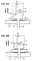
- Fig. 12A is a schematic illustration of the limiter device prior to use.
- Fig. 12B is a schematic illustration of the limiter device in use.
- the present invention provides a number of novel and non-obvious improvements over the Mechanical Limiter Switch as disclosed in U.S. Patent Application Ser. No. 60/434,297 and U.S. Application Ser. No. 10/739,252 .
- the present invention provides a mechanical limiter device which is used for shutting off an electrical device after it has been used a pre-determined number of times.
- the present system is particularly useful with medical devices since such devices should only be operated a small number of times before they are disposed.
- Figs. 1 to 3B show preferred embodiments of a mechanical limiter device having a one or two-part housing, with the housing received onto a pair of carrier pins.
- Figs. 4A to 4C show various embodiments of the mechanical limiter device mounted to, or formed integral with, a printed circuit board.
- Fig. 5 shows an embodiment of the mechanical limiter device with an electrically conductive coating on the teeth of the device.
- Figs. 6 to 9 show an embodiment of the mechanical limiter device having a two-part housing, with separate inner and outer portions, and with the slot formed in the outer portion of the housing.
- Figs. 10A and 10B show an embodiment of the mechanical limiter device having a cut-out section near the distal end of the outer portion of the housing, for receiving a spring therein.
- Figs. 11A and 11B show an embodiment of the mechanical limiter device mounted onto a printed circuit board with a chamfered edge on the outer surface of the housing.
- Fig. 12A is a schematic illustration of an optional embodiment of the present limiter device prior to use.
- Fig. 12B is a schematic illustration of an optional embodiment of the present limiter device in use.
- a mechanical limiter device 10 is provided.
- Device 10 includes a housing 12 having a slot 14 passing at least partially therearound. As can be seen, slot 14 forms a plurality of teeth 16 in a side of housing 12.
- a plunger 20 is movable back and forth within housing 12. End of the spring. For example, contact member 25 may alternately be positioned at a mid point of the spring, or even at a distal end of the spring.
- Fig. 2 shows a side perspective view of another embodiment of device 10 with carrier pins 30 removed.
- spring 22 is receivable into housing 12 through a large side channel 13 in housing 12.
- spring 22 is inserted into housing 12 through side channel 13 with the proximal end of spring 22 forming contact member 25, and the distal end 27 of spring 22 positioned at the distal end of side channel 13.
- plunger 20 may then be advanced through the center of spring 22 to assemble the device.
- the distal end 21 of plunger 20 may be barbed (and protrude through a small hole in the distal end of housing 12).
- distal end 27 of spring 22 may also act as an electrical contact point.
- one of carrier pins 30 may act as an electrical contact point.
- contact member 25 may be rotated into a final position where it contacts one of carrier pins 30.
- contact member 25 may be rotated into a final position where it contacts some other contact pin or member to open or close an electrical circuit.
- Figs. 3A and 3B show embodiments of the invention having a two-part housing, as follows.
- Device 10 in Fig. 3A has housing 12 made from separate first and second portions 12A and 12B, respectively.
- portion 12A is the distal portion of the housing and portion 12B is the proximal portion of the housing.
- Portions 12A and 12B are both mounted sequentially onto carrier pins 30.
- slot 14 is formed in the space between portions 12A and 12B.
- portion 12C is the distal portion of the housing and portion 12D is the proximal portion of the housing.
- portions 12A and 12B, or 12C and 12D can be made of different materials.
- one portion may be made of an electrically conducting material (e.g.: metal), while the other portion mad be made of an electrically insulating material (e.g.: plastic).
- both portions may be made of the same material.
- both may be made by injection molding plastic. If molded simultaneously, an off-set injection molding process can be used.
- the housing of the present invention made be manufactured inexpensively and at low cost.
- Fig. 4A shows an embodiment of device 10 positioned to be mounted onto a printed circuit board 40.
- a pair of carrier pins 30 are first positioned on printed circuit board 40.
- carrier pins 30 have barbed tips 31.
- Device 10 is slidably received down onto carrier pins 30 with barbed tips 31 projecting through side apertures 15 in the housing. (Side apertures 15 are also seen in Fig. 2 ).
- plunger 20 When device 10 is thus secured onto printed circuit board 40, the distal end of plunger 20 will protrude through an opening 41 in the printed circuit board 40. When the associated medical (or electrical) device is activated, it will be plugged into printed circuit board 40, causing plunger 20 to be moved in a distal direction, thus initialing the functioning of the mechanical limiter device 10. (Additional electric contact pins 42 in electrical contact with printed circuit board 40 are shown for comparison).
- Fig. 4B shows an alternate embodiment of the invention in which housing of the mechanical limiter device and the printed circuit board are integrally formed with one another together as a single block 45.
- the printed circuit board and the limiter device housing may be injection molded as a single, inseparable, body.
- Fig. 4C shows an alternate embodiment of the invention in which the housing of the mechanical limiter device and the printed circuit board and a flex circuit 46 are all formed together as a single unit 48.
- Such system advantageously provides various mounting pins and surface mount components.
- Fig. 5 shows an embodiment of the invention wherein teeth 16 are coated by an electrically conductive material 17 (which may include metalized plastic).
- the remainder of housing 12 may optionally be made of non-conducting plastic.
- Figs. 6 to 10B show an embodiment of the invention in which limiter device 50 also has a two-part housing.
- the housing comprises an inner portion 52 and an outer portion 54.
- the inner portion 52 is made of an electrically non-conducting material
- the outer portion 54 is made of an electrically conducting material.
- the slot 14 (and teeth 16) in the housing are formed solely by the outer portion 54 of the housing, as shown.
- outer portion 54 of the housing comprises a bendable tab 55 at its distal end.
- Tab 55 is configured to hold the distal end of the biasing mechanism against movement of plunger 20. Tab 55 also secures inner portion 52 of the housing. As shown in Fig. 6 , tab 55 is formed into outer portion 54 of the housing, initially projecting in a distal direction. As shown in Fig. 7 , once inner portion 52 is received into outer portion 54, tab 55 is bent down. Thereafter, spring 22 is loaded into the device (in a manner as described above). Tab 55 will then hold the distal end 27 of spring 22 in position as the spring expands. An advantage of this design is that it replaces the need for additional components such as a cap to hold the spring in place. In addition, tab 55 provides electrical contact with distal end 27 of spring 22.
- Figs. 8A and 8B show further details of the structure of the inner portion 52 of the housing.
- a pair of tabs 53 may be formed into inner portion 52.
- an electrical contact pin 56 may be secured to inner portion 52 by tabs 53.
- tabs 53 may be bendable, to further hold electrical contact pin 56 in a fixed stationary position within device 50. Such bendable tabs avoid the need for adhesives to retain contact pin 56 in place.
- Inner portion 52 of the housing also has a side opening 13 in which spring 22 is received (as was described with respect to Fig. 2 , above).
- inner portion 52 has a wide window area 51 (contiguous with side opening 13) through which contact member 25 rotates.
- An advantage of having a wide window area 51 in inner portion 52 is that the same inner portion 52 may be used with a variety of different outer portions 54, each having different tooth and slot patterns therein.
- contact member 25 touches stationary contact pin 56 when contact member 25 has advanced past each of the plurality of teeth 16 in slot 14.
- IE when contact pin 25 reaches its final position at the end of slot 14.
- the proximal end of contact pin 56 is also shown in Fig. 7 ).
- contact pin 56 adds the option of either opening or closing the circuit.
- contact pin 56 further advantageously adds structural integrity to the device.
- Fig. 9 shows an embodiment of the invention in which the distal end 21 of plunger 20 is received through a hole in bendable tab 55.
- An advantage of this embodiment of the invention is that it provides coaxial stability to the device.
- Figs. 10A and 10B show a further embodiment of the invention having a cut-out section 59 near the distal end of outer portion 54 of the housing.
- cut-out section 59 is dimensioned to receive a distal end 27 of a spring therein.
- the contact member 25 is formed by the proximal end of the spring.
- a leg of spring 22 may optionally pass along the outer surface of inner portion 52 of the housing.
- Figs. 11A and 11B show a proximal end of the inner portion of the housing having a chamfered edge 57 (also seen in Figs. 10A and 10B ).
- An advantage of chamfered edge 57 is that it allows a solder meniscus 49 to form when soldering the outer portion 54 of the housing to the surface of printed circuit board 40.
- Figs. 12A and 12B show an additional optional feature of the present invention which prevents an operator from using a medical (or other electrical) device without activating device 10 (or 50). Specifically, since an operator may realize activation of the present limiter device requires plunger 20 to be depressed, (s)he may be tempted to simply cut off the proximal end of plunger 20 (i.e.: the portion of the plunger projecting through opening 41 in printed circuit board 40) in the hopes that the limiter device is not activated.
- the proximal end of plunger 20 may include an electrical contact 60 thereon.
- Printed circuit board 40 may include an electrical contact 61 thereon.
- electrical contacts 60 and 61 touch one another. (Such contacts 60 and 61 may be used to short out the associated medical device prior to use).
- a portion of the housing of the limiter device (10 or 50) is shown in dotted lines. Slot 14 and teeth 16 are also shown in dotted lines.
- plunger 20 is depressed (i.e.: moved distally) to activate the limiter device (10 or 50) and thus turn on the associated medical device.
- contact member 25 moves along through slot 14 past the first tooth 16 when plunger 20 is depressed. As can be seen, this movement causes electrical contact 60 and 61 to separate. Consequently, the associated medical device is no longer shorted out.
- patterning of conductive and non-conductive portions of teeth 16 may also be used to prevent an operator from avoiding activation of the limiter device (by cutting off the proximal end of plunger 20) once contact member 25 has been advanced past the first tooth in slot 14. IE: once electrical contacts 60 and 61 have been separated.
- a method of limiting the number of uses of an electrical device is provided.
- Such electrical device may include, but is not limited to, a medical device.
- a method may include distally advancing a biased plunger 20 into a housing 12 of a mechanical limiter device 10 each time the electrical device is activated.
- the biased plunger 20 retracts (proximally) from the housing 12 each time the electrical device is de-activated.
- the mechanical limiter device 10 has a contact member 25 extending through a slot 14 in the side of the housing 12, with slot 14 forming a series of teeth 16, wherein contact member 25 is configured to advance past one of each of the plurality of teeth 16 in slot 14 each time plunger 20 is moved back and forth within the housing.
- movement of plunger 20 back and forth within housing 12 causes contact member 25 to advance into contact with a contact pin or member, thereby either completing or shorting out an electrical circuit.
- a method of forming a mechanical limiter device may include injection molding a first portion (12A or 52) of a housing; injection molding a second portion of the housing (12B or 54); assembling the first and second portions of the housing together; inserting a spring 22 into the housing; and inserting a plunger 20 into the housing, plunger 20 being received within spring 22.
- the first and second portions of the housing may be injection molded simultaneously in an offset injection molding process.
- An advantage of such off-set molding is that the second portion of the housing (i.e.: the distal end of the housing) can have a greater radial thickness than the first portion of the housing (i.e.: the proximal end of the housing).
- This design may be used to provide a distal end of greater radial thickness than the proximal end of the device.
- the teeth 16 formed by the distal end of the device can be made thicker, thereby providing more torque on contact member 25 of spring 22.
- a second advantage of having the proximal end of the limiter device be of a smaller diameter than the distal end is that the proximal end of the device does not impinge on other components mounted onto the printed circuit board.
Landscapes
- Electrotherapy Devices (AREA)
- Coupling Device And Connection With Printed Circuit (AREA)
- Measurement Of The Respiration, Hearing Ability, Form, And Blood Characteristics Of Living Organisms (AREA)
- Transmission Devices (AREA)
- Crushing And Grinding (AREA)
- Mechanical Control Devices (AREA)
- Earth Drilling (AREA)
Abstract
Description
- In general, the present invention relates to mechanical devices that limit the number of times an electrical device can be used. In particular, the present invention relates to mechanical switches that prevent medical devices from being used more than a few times.
- Use-Limiter devices are used to prevent medical devices from being used more than the pre-determined number of uses designated by the manufacturer. For example, it may be desirable that a typical medical device is only operated three to five times. Once the device has reached the manufacturer's specificnumber of uses then the device is permanently disabled and cannot be reused, reconditioned or refurbished in any wayAfter that, the device should be disposed (for reasons of patient safety).
- For example, International application
WO 01/80932 A1 - Problems with such system include the fact that they typically include electrical controllers. Installing such electrical controllers may necessitate retrofitting both the controller, and the medical device itself. A further problem common to such systems is that they rely on integrated circuits, and that the memories of such integrated circuits may be damaged by typical sterilization procedures, such as X rays.
- The present invention provides a mechanical limiter device according to claim 1 that can be used to either open or close a circuit, and/or change the inductance, capacitance, and/or resistance of an electrical system.
- In preferred embodiments, the present invention provides a mechanical use-limiting device, including: a housing having a slot passing at least partially therearound, the slot forming a plurality of teeth in a side of the housing; a plunger movable within the housing; a biasing mechanism configured to urge the plunger in a proximal direction within the housing; and a contact member extending through the slot in the side of the housing, the contact member being configured to advance past at least one of each of the plurality of teeth in the slot each time the plunger is moved back and forth within the housing. In preferred aspects, the number of times the device can be activated equals the number of teeth in the slot in the side of the housing.
- In preferred aspects, the biasing mechanism is a spring, and the contact member is an end of the spring. Also in preferred aspects, the spring is receivable into the housing through a side channel in the housing. In preferred aspects, the housing may comprise separate first and second portions, wherein the slot is formed in a space between the separate first and second portions.
- In preferred embodiments, the housing is slidably received onto a pair of carrier pins which are in turn mounted on a printed circuit board. A flex circuit may optionally be mounted onto the printed circuit board.
- In other preferred embodiments, the housing comprises: an inner portion made of an electrically non-conducting material; and an outer portion made of an electrically conducting material. In these embodiments, the slot in the housing may be formed solely by the outer portion of the housing.
- The present invention also provides a method of limiting the number of uses of an electrical device, by: advancing a biased plunger into a housing of a mechanical limiter device each time the electrical device is activated, and allowing the biased plunger to retract from the housing each time the electrical device is de-activated, wherein the mechanical limiter device has a contact member extending through a slot in the side of its housing, the slot forming a series of teeth, wherein the contact member is configured to advance past at least one of each of the plurality of teeth in the slot each time the plunger is moved back and forth within the housing.
- A first advantage of the present invention is that it is not damaged by typical sterilization procedures, such as Gamma, ETO, E-Beam, AutoClave, etc.
- A second advantage of the present invention is that it is physically small, but can be easily assembled for use inexpensively and in a short period of time.
-
Fig. 1 is a perspective view of a first embodiment of the present invention having a one piece housing, wherein the spring is loaded distally. -
Fig. 2 is a perspective view of another embodiment of the invention having a one-piece housing, wherein the spring is loaded through the side of the housing. -
Fig. 3A is a perspective view of a second embodiment of the present invention having a two piece housing. -
Fig. 3B is a perspective view of a another embodiment of the present invention having a two piece housing. -
Fig. 4A is a perspective view of the mechanical limiter device ofFig. 1 , positioned for mounting onto a printed circuit board. -
Fig. 4B is a perspective view of the mechanical limiter device ofFig. 1 , integrally formed into a printed circuit board. -
Fig. 4C is a perspective view of the mechanical limiter device ofFig. 1 , positioned for receipt onto a printed circuit board, with a flex circuit also disposed on the printed circuit board. -
Fig. 5 is a perspective view of an embodiment of the invention having an electrically conductive material coating the teeth of the slot. -
Fig. 6 is a perspective view of an embodiment of the invention having a housing with inner and outer portions, the outer portion having a bendable tab at its distal end. -
Fig. 7 is a second perspective view of the device ofFig. 6 , with the tab bent to hold the distal ends of the inner portion of the housing and the spring. -
Fig. 8A is a perspective view of the inner portion of the housing of the device ofFigs. 6 and 7 prior to receiving a contact pin therein. -
Fig. 8B is a perspective view of the inner portion of the housing of the device ofFigs. 6 and 7 after receiving a contact pin therein. -
Fig. 9 is a perspective view of an embodiment of the invention similar to that shown inFig. 6 , but with the plunger extending through the tab at the distal end of the housing. -
Fig. 10A is a first perspective view of an embodiment of the invention having a cut-out section near the distal end of the outer portion of the housing, for retention of a spring after loading. -
Fig. 10B is a second perspective view of the embodiment of the invention having a cut-out section near the distal end of the outer portion of the housing, showing a spring received therethrough, for retention of a spring after loading. -
Fig. 11A is a perspective view of an embodiment of the present invention mounted onto a printed circuit board. -
Fig. 11B is a close-up view of a portion of the device shown inFig. 11A , showing a chamfered edge on the outer surface of the housing, with a solder meniscus adjacent thereto. -
Fig. 12A is a schematic illustration of the limiter device prior to use. -
Fig. 12B is a schematic illustration of the limiter device in use. - Basic operation of a mechanical limiter device can be understood by referring to
Figs. 1 to 4 , and associated description, ofapplication 10/739,252. Further details of the operation of various mechanical limiter device embodiments of the invention are seen inFigs. 5a to 11b ofapplication 10/739,252 - However, the present invention provides a number of novel and non-obvious improvements over the Mechanical Limiter Switch as disclosed in
U.S. Patent Application Ser. No. 60/434,297 andU.S. Application Ser. No. 10/739,252 . - The present invention provides a mechanical limiter device which is used for shutting off an electrical device after it has been used a pre-determined number of times. The present system is particularly useful with medical devices since such devices should only be operated a small number of times before they are disposed.
-
Figs. 1 to 3B show preferred embodiments of a mechanical limiter device having a one or two-part housing, with the housing received onto a pair of carrier pins. -
Figs. 4A to 4C show various embodiments of the mechanical limiter device mounted to, or formed integral with, a printed circuit board. -
Fig. 5 shows an embodiment of the mechanical limiter device with an electrically conductive coating on the teeth of the device. -
Figs. 6 to 9 show an embodiment of the mechanical limiter device having a two-part housing, with separate inner and outer portions, and with the slot formed in the outer portion of the housing. -
Figs. 10A and10B show an embodiment of the mechanical limiter device having a cut-out section near the distal end of the outer portion of the housing, for receiving a spring therein. -
Figs. 11A and 11B show an embodiment of the mechanical limiter device mounted onto a printed circuit board with a chamfered edge on the outer surface of the housing. -
Fig. 12A is a schematic illustration of an optional embodiment of the present limiter device prior to use. -
Fig. 12B is a schematic illustration of an optional embodiment of the present limiter device in use. - Referring first to
Fig. 1 , amechanical limiter device 10 is provided.Device 10 includes ahousing 12 having aslot 14 passing at least partially therearound. As can be seen, slot 14 forms a plurality ofteeth 16 in a side ofhousing 12. Aplunger 20 is movable back and forth withinhousing 12.
end of the spring. For example,contact member 25 may alternately be positioned at a mid point of the spring, or even at a distal end of the spring. -
Fig. 2 shows a side perspective view of another embodiment ofdevice 10 with carrier pins 30 removed. As can be seen,spring 22 is receivable intohousing 12 through alarge side channel 13 inhousing 12. Specifically,spring 22 is inserted intohousing 12 throughside channel 13 with the proximal end ofspring 22 formingcontact member 25, and thedistal end 27 ofspring 22 positioned at the distal end ofside channel 13. Afterspring 22 has been inserted intohousing 12 throughside channel 13,plunger 20 may then be advanced through the center ofspring 22 to assemble the device. As can also be seen inFigs. 1 and 2 , thedistal end 21 ofplunger 20 may be barbed (and protrude through a small hole in the distal end of housing 12). As such, onceplunger 20 has been advanced through the center ofspring 22, with itsdistal end 21 projecting out through the distal end ofhousing 12, the barbeddistal end 21 ofplunger 20 will prevent removal ofplunger 20 fromhousing 12, thus ensuring thatspring 22 is always properly positioned inside housing 12. Afterwards,device 10 may be mounted onto carrier pins 30, with one of carrier pins 30 coveringside channel 13 inhousing 12. An advantage of the design of the present invention illustrated inFigs. 1 and 2 is its ease of assembly. - In various embodiments of the invention,
distal end 27 ofspring 22 may also act as an electrical contact point. Moreover, in various embodiments of the invention, one of carrier pins 30 may act as an electrical contact point. Specifically,contact member 25 may be rotated into a final position where it contacts one of carrier pins 30. As will be explained, in other embodiments,contact member 25 may be rotated into a final position where it contacts some other contact pin or member to open or close an electrical circuit. -
Figs. 3A and 3B show embodiments of the invention having a two-part housing, as follows.Device 10 inFig. 3A hashousing 12 made from separate first andsecond portions portion 12A is the distal portion of the housing andportion 12B is the proximal portion of the housing.Portions slot 14 is formed in the space betweenportions Fig. 3B , whereportion 12C is the distal portion of the housing and portion 12D is the proximal portion of the housing. - An advantage of the design of the present invention as shown in
Figs. 3A and 3B is thatportions Figs. 3A and 3B , the spring is loaded betweenportions -
Fig. 4A shows an embodiment ofdevice 10 positioned to be mounted onto a printedcircuit board 40. Specifically, a pair of carrier pins 30 are first positioned on printedcircuit board 40. Preferably, carrier pins 30 havebarbed tips 31.Device 10 is slidably received down onto carrier pins 30 withbarbed tips 31 projecting throughside apertures 15 in the housing. (Side apertures 15 are also seen inFig. 2 ). - When
device 10 is thus secured onto printedcircuit board 40, the distal end ofplunger 20 will protrude through anopening 41 in the printedcircuit board 40. When the associated medical (or electrical) device is activated, it will be plugged into printedcircuit board 40, causingplunger 20 to be moved in a distal direction, thus initialing the functioning of themechanical limiter device 10. (Additional electric contact pins 42 in electrical contact with printedcircuit board 40 are shown for comparison). -
Fig. 4B shows an alternate embodiment of the invention in which housing of the mechanical limiter device and the printed circuit board are integrally formed with one another together as asingle block 45. For example, the printed circuit board and the limiter device housing may be injection molded as a single, inseparable, body. -
Fig. 4C shows an alternate embodiment of the invention in which the housing of the mechanical limiter device and the printed circuit board and aflex circuit 46 are all formed together as asingle unit 48. Such system advantageously provides various mounting pins and surface mount components. -
Fig. 5 shows an embodiment of the invention whereinteeth 16 are coated by an electrically conductive material 17 (which may include metalized plastic). The remainder ofhousing 12 may optionally be made of non-conducting plastic. An advantage of this design is thatcontact member 25 can be maintained in electrical contact with carrier pins 30 during its progress alongslot 14 past each ofteeth 16. (In various alternate embodiments, electrical contact ofcontact member 25 does not occur untilcontact member 25 moves into its final position in slot 14). -
Figs. 6 to 10B show an embodiment of the invention in whichlimiter device 50 also has a two-part housing. In this embodiment, the housing comprises aninner portion 52 and anouter portion 54. Preferably, theinner portion 52 is made of an electrically non-conducting material, and theouter portion 54 is made of an electrically conducting material. In this embodiment, the slot 14 (and teeth 16) in the housing are formed solely by theouter portion 54 of the housing, as shown. Optionally,outer portion 54 of the housing comprises abendable tab 55 at its distal end. -
Tab 55 is configured to hold the distal end of the biasing mechanism against movement ofplunger 20.Tab 55 also securesinner portion 52 of the housing. As shown inFig. 6 ,tab 55 is formed intoouter portion 54 of the housing, initially projecting in a distal direction. As shown inFig. 7 , onceinner portion 52 is received intoouter portion 54,tab 55 is bent down. Thereafter,spring 22 is loaded into the device (in a manner as described above).Tab 55 will then hold thedistal end 27 ofspring 22 in position as the spring expands. An advantage of this design is that it replaces the need for additional components such as a cap to hold the spring in place. In addition,tab 55 provides electrical contact withdistal end 27 ofspring 22. -
Figs. 8A and8B show further details of the structure of theinner portion 52 of the housing. A pair oftabs 53 may be formed intoinner portion 52. As shown inFig. 8B , anelectrical contact pin 56 may be secured toinner portion 52 bytabs 53. In preferred embodiments,tabs 53 may be bendable, to further holdelectrical contact pin 56 in a fixed stationary position withindevice 50. Such bendable tabs avoid the need for adhesives to retaincontact pin 56 in place.Inner portion 52 of the housing also has aside opening 13 in which spring 22 is received (as was described with respect toFig. 2 , above). In addition,inner portion 52 has a wide window area 51 (contiguous with side opening 13) through whichcontact member 25 rotates. An advantage of having awide window area 51 ininner portion 52 is that the sameinner portion 52 may be used with a variety of differentouter portions 54, each having different tooth and slot patterns therein. - In accordance with this embodiment of the invention,
contact member 25 touchesstationary contact pin 56 whencontact member 25 has advanced past each of the plurality ofteeth 16 inslot 14. IE: whencontact pin 25 reaches its final position at the end ofslot 14. (The proximal end ofcontact pin 56 is also shown inFig. 7 ). As such,contact pin 56 adds the option of either opening or closing the circuit. Moreover,contact pin 56 further advantageously adds structural integrity to the device. -
Fig. 9 shows an embodiment of the invention in which thedistal end 21 ofplunger 20 is received through a hole inbendable tab 55. An advantage of this embodiment of the invention is that it provides coaxial stability to the device. -
Figs. 10A and10B show a further embodiment of the invention having a cut-outsection 59 near the distal end ofouter portion 54 of the housing. As shown inFig. 10B , cut-outsection 59 is dimensioned to receive adistal end 27 of a spring therein. As illustrated, thecontact member 25 is formed by the proximal end of the spring. As also shown inFig. 10B , a leg ofspring 22 may optionally pass along the outer surface ofinner portion 52 of the housing. An advantage of this design is thatdevice 50 may be plugged directly into printedcircuit board 40, saving assembly time and avoiding the need for additional parts. -
Figs. 11A and 11B show a proximal end of the inner portion of the housing having a chamfered edge 57 (also seen inFigs. 10A and10B ). An advantage of chamferededge 57 is that it allows asolder meniscus 49 to form when soldering theouter portion 54 of the housing to the surface of printedcircuit board 40. -
Figs. 12A and 12B show an additional optional feature of the present invention which prevents an operator from using a medical (or other electrical) device without activating device 10 (or 50). Specifically, since an operator may realize activation of the present limiter device requiresplunger 20 to be depressed, (s)he may be tempted to simply cut off the proximal end of plunger 20 (i.e.: the portion of the plunger projecting through opening 41 in printed circuit board 40) in the hopes that the limiter device is not activated. - As shown in
Fig. 12A , the proximal end ofplunger 20 may include anelectrical contact 60 thereon. Printedcircuit board 40 may include anelectrical contact 61 thereon. As can be seen, prior to use,electrical contacts Such contacts Slot 14 andteeth 16 are also shown in dotted lines. - As shown in
Fig. 12B ,plunger 20 is depressed (i.e.: moved distally) to activate the limiter device (10 or 50) and thus turn on the associated medical device. As explained above,contact member 25 moves along throughslot 14 past thefirst tooth 16 whenplunger 20 is depressed. As can be seen, this movement causeselectrical contact - As can be seen, should an operator initially cut the proximal end of
plunger 20 off, hoping to avoid the activation of the limiter device, the device will simply remain in the position shown inFig. 12A , withelectrical contacts - In additional embodiments, patterning of conductive and non-conductive portions of
teeth 16 may also be used to prevent an operator from avoiding activation of the limiter device (by cutting off the proximal end of plunger 20) oncecontact member 25 has been advanced past the first tooth inslot 14. IE: onceelectrical contacts - In a further aspect of the present invention, a method of limiting the number of uses of an electrical device is provided. Such electrical device may include, but is not limited to, a medical device. As shown throughout the attached figures, such method may include distally advancing a
biased plunger 20 into ahousing 12 of amechanical limiter device 10 each time the electrical device is activated. Thebiased plunger 20 retracts (proximally) from thehousing 12 each time the electrical device is de-activated. In this preferred method, themechanical limiter device 10 has acontact member 25 extending through aslot 14 in the side of thehousing 12, withslot 14 forming a series ofteeth 16, whereincontact member 25 is configured to advance past one of each of the plurality ofteeth 16 inslot 14 eachtime plunger 20 is moved back and forth within the housing. In preferred aspects of this method, movement ofplunger 20 back and forth withinhousing 12 causescontact member 25 to advance into contact with a contact pin or member, thereby either completing or shorting out an electrical circuit. - In a further aspect of the present invention, a method of forming a mechanical limiter device is provided. Such method may include injection molding a first portion (12A or 52) of a housing; injection molding a second portion of the housing (12B or 54); assembling the first and second portions of the housing together; inserting a
spring 22 into the housing; and inserting aplunger 20 into the housing,plunger 20 being received withinspring 22. - In preferred aspects of the method, the first and second portions of the housing may be injection molded simultaneously in an offset injection molding process. An advantage of such off-set molding is that the second portion of the housing (i.e.: the distal end of the housing) can have a greater radial thickness than the first portion of the housing (i.e.: the proximal end of the housing). This design may be used to provide a distal end of greater radial thickness than the proximal end of the device. As such, the
teeth 16 formed by the distal end of the device can be made thicker, thereby providing more torque oncontact member 25 ofspring 22. A second advantage of having the proximal end of the limiter device be of a smaller diameter than the distal end is that the proximal end of the device does not impinge on other components mounted onto the printed circuit board.
Claims (22)
- A mechanical limiter (10) for use with an electrical device, comprising:a housing (12) having a slot (14) passing at least partially therearound; anda plunger (20) movable within the housing (12),characterized bysaid plunger (20) having an electrically conductive material (60) associated with a proximal end thereof;a biasing mechanism (22) configured to proximally urge the plunger (20) into a position where the electrically conductive material (60) of the plunger contacts another electrical contact (61); anda contact member (25) extending through the slot (14) in the side of the housing (12), the contact member (25) being configured to move within the slot (14) each time the plunger (20) is moved back and forth within the housing (12).
- The mechanical limiter of claim 1, wherein the slot (14) permits back and forth movement of the contact member (25) within the slot (14).
- The mechanical limiter of claim 2, wherein the slot (14) forms a plurality of teeth (16), and the number of times the device can be activated equals the number of pairs of teeth (16) in the slot (14).
- The mechanical limiter device of claim 3, wherein the teeth (16) are coated with an electrically conducting material.
- The mechanical limiter of claim 1, wherein the biasing mechanism is a spring (22) and the contact member (25) is an end of the spring (22).
- The mechanical limiter of claim 1, wherein the housing (12) comprises separate first and second portions (12A, 12B), with the slot (14) being formed in a space between the first and second portions (12A, 12B) of the housing (12).
- The mechanical limiter of claim 1, wherein a distal end of the plunger (20) protrudes through an opening in the distal end of the housing (12), and the distal end of the plunger (20) is barbed.
- The mechanical limiter device of claim 1, wherein the contact member (25) is configured to advance along the slot (14).
- The mechanical limiter device of claim 1, wherein the slot (14) is defined in a side of the housing (12) and the side of the housing (12) is configured to receive a pair of carrier pins (30).
- The mechanical limiter of claim 9, wherein the biasing mechanism (22) is receivable into the housing (12) through a side channel defined in the housing (12), and wherein one of the carrier pins (30) is receivable over the side channel in the housing (12).
- The mechanical limiter device of claim 1, wherein the housing (12) is configured to be received onto a pair of carrier pins (30).
- The mechanical limiter device of claim 11, wherein the housing (12) is further configured to accept carrier pins (30) that are barbed.
- The mechanical limiter device of claim 9, wherein each of the pair of carrier pins (30) are mounted onto a printed circuit board (40).
- The mechanical limiter device of claim 1, wherein a distal end of the plunger (20) protrudes through an opening in the distal end of the housing (12), and wherein the distal end of the plunger (20) is barbed.
- The mechanical limiter device of claim 1, wherein the housing comprises:an inner portion (52) made of an electrically non-conducting material; andan outer portion (54) made of an electrically conducting material, with the slot (14) being formed in the outer portion (54).
- The mechanical limiter device of claim 15, wherein the outer portion (54) has a cut-out section (59) near the distal end thereof for receiving the spring (22) therein.
- The mechanical limiter device of claim 16, further comprising a tab (55) extending from the distal end of the housing for holding the spring (22) inside the housing. in soldering the housing device to the surface of the printed circuit board (40).
- The mechanical limiter device of claim 1, further comprising a chamfered edge (57) at a proximal end of the housing for association with a surface of a printed circuit board (40), said chamfered edge (57) being configured to accommodate a solder meniscus to assist in soldering the housing device to the surface of the printed circuit board (40).
- The mechanical limiter device of claim 1, wherein the housing (12) at the distal end has a greater radial thickness than the housing (12) at the proximal end.
- The mechanical limiter device of claim 1, further comprising a printed circuit board (40) extending therefrom, wherein the proximal end of the plunger (20) is in contact with the printed circuit board (40) prior to distally advancing the plunger (20), and the proximal end of the plunger (20) is not in contact with the printed circuit board (40) after the plunger (20) has been distally advanced.
- A method of limiting the use of an electrical device using the mechanical limiter of any of claims 1 to 20, comprising:biasing the plunger in a proximal direction such that the electrically conductive surface of the plunger is in contact with another electrically conductive surface such that the electrical connection between the two surfaces produces an electrical short,moving the plunger distally such that the electrically conductive surface of the plunger separates from the other electrically conductive surface in order to electrically activate an electrical device.
- The method of claim 21, wherein the electrical device is a medical device.
Applications Claiming Priority (2)
| Application Number | Priority Date | Filing Date | Title |
|---|---|---|---|
| US10/819,906 US7075023B2 (en) | 2002-12-17 | 2004-04-06 | Pushbutton mechanical limiter switch including movable contact located in housing passage way |
| PCT/US2005/011779 WO2005101436A1 (en) | 2004-04-06 | 2005-04-06 | Mechanical limiter device |
Publications (2)
| Publication Number | Publication Date |
|---|---|
| EP1733405A1 EP1733405A1 (en) | 2006-12-20 |
| EP1733405B1 true EP1733405B1 (en) | 2009-03-04 |
Family
ID=34965558
Family Applications (1)
| Application Number | Title | Priority Date | Filing Date |
|---|---|---|---|
| EP05734961A Expired - Lifetime EP1733405B1 (en) | 2004-04-06 | 2005-04-06 | Mechanical limiter device |
Country Status (5)
| Country | Link |
|---|---|
| US (2) | US7075023B2 (en) |
| EP (1) | EP1733405B1 (en) |
| AT (1) | ATE424617T1 (en) |
| DE (1) | DE602005013070D1 (en) |
| WO (1) | WO2005101436A1 (en) |
Families Citing this family (16)
| Publication number | Priority date | Publication date | Assignee | Title |
|---|---|---|---|---|
| US7075023B2 (en) * | 2002-12-17 | 2006-07-11 | Medconx, Inc. | Pushbutton mechanical limiter switch including movable contact located in housing passage way |
| US6846996B2 (en) * | 2002-12-17 | 2005-01-25 | Medconx, Inc. | Pushbutton mechanical limiter switch including movable contact with conductive radial segment located in serrated housing passageway |
| US8996486B2 (en) * | 2004-12-15 | 2015-03-31 | Applied Invention, Llc | Data store with lock-free stateless paging capability |
| US7435112B1 (en) | 2008-02-08 | 2008-10-14 | Tyco Electronics Corporation | Electrical connector having a mechanical mating cycle limitation |
| US7632126B1 (en) * | 2008-05-23 | 2009-12-15 | Tyco Electronics Corporation | High density circular interconnect with bayonet action |
| US7976342B2 (en) * | 2008-06-04 | 2011-07-12 | Tyco Electronics Corporation | High density rectangular interconnect |
| US8367953B2 (en) * | 2008-06-17 | 2013-02-05 | Mac Valves, Inc. | Pneumatic system electrical contact device |
| US8764487B2 (en) | 2011-05-05 | 2014-07-01 | Precision Concepts Group Llc | Connector assembly, device, and kit |
| US9147950B2 (en) | 2011-05-25 | 2015-09-29 | Precision Concepts Group Llc | Connector assembly and device and methods of assembling same |
| US10132408B2 (en) * | 2016-08-17 | 2018-11-20 | GM Global Technology Operations LLC | Park actuator assembly for an automatic transmission and a transmission including a park actuator assembly |
| US10003135B1 (en) | 2017-03-23 | 2018-06-19 | Atl Technology, Llc | Mechanical use-limiting connector for electrical tool |
| US10665995B2 (en) | 2017-03-23 | 2020-05-26 | Atl Technology, Llc | Mechanical use-limiting connector for electrical tool |
| GB2562853B (en) * | 2017-03-23 | 2021-06-30 | Atl Tech Llc | Mechanical use-limiting connector for electrical tool |
| US10495223B2 (en) | 2018-01-11 | 2019-12-03 | GM Global Technology Operations LLC | Shift by wire parking system |
| US10914378B2 (en) * | 2019-05-07 | 2021-02-09 | GM Global Technology Operations LLC | Roller-gear shift by wire parking system |
| US12322912B2 (en) | 2023-03-06 | 2025-06-03 | International Business Machines Corporation | Plug count limiter for cables |
Family Cites Families (16)
| Publication number | Priority date | Publication date | Assignee | Title |
|---|---|---|---|---|
| US233087A (en) * | 1880-10-12 | Jambs h | ||
| US3226496A (en) * | 1964-09-15 | 1965-12-28 | Radio Frequency Lab Inc | Rotary electrical switch with improved spring contact and rotor structure |
| US3548137A (en) * | 1968-06-20 | 1970-12-15 | Chicago Switch Inc | Switch construction |
| DE2854096C2 (en) * | 1978-12-14 | 1982-04-08 | Siemens AG, 1000 Berlin und 8000 München | Key switches, in particular for keyboards in typewriters and similar devices |
| US4284862A (en) * | 1980-03-20 | 1981-08-18 | The United States Of America As Represented By The Secretary Of The Army | Acceleration switch |
| US4533803A (en) * | 1983-10-17 | 1985-08-06 | The Singer Company | Switch construction |
| US5678802A (en) * | 1995-11-06 | 1997-10-21 | Valterra Products, Inc. | Cable guide casing apparatus |
| US6204493B1 (en) * | 1998-08-21 | 2001-03-20 | Drexel University | Fault tolerant electric current regulator |
| US6364286B1 (en) * | 1999-08-19 | 2002-04-02 | Bpc Manufacturing, Inc. | Manually actuated valve |
| US6237604B1 (en) | 1999-09-07 | 2001-05-29 | Scimed Life Systems, Inc. | Systems and methods for preventing automatic identification of re-used single use devices |
| US6204463B1 (en) | 1999-12-21 | 2001-03-20 | Methode Electronics Malta Ltd. | Self-adjusting switch mechanism with anti-adjustment protection |
| WO2001080932A1 (en) | 2000-04-26 | 2001-11-01 | Smithkline Beecham Biologicals S.A. | Restricted use syringe |
| US20040245179A1 (en) | 2001-12-21 | 2004-12-09 | Elsegood Stewart D. | Magnetic fluid filter adapter |
| US6849074B2 (en) * | 2002-06-17 | 2005-02-01 | Medconx, Inc. | Disposable surgical devices |
| US6846996B2 (en) * | 2002-12-17 | 2005-01-25 | Medconx, Inc. | Pushbutton mechanical limiter switch including movable contact with conductive radial segment located in serrated housing passageway |
| US7075023B2 (en) * | 2002-12-17 | 2006-07-11 | Medconx, Inc. | Pushbutton mechanical limiter switch including movable contact located in housing passage way |
-
2004
- 2004-04-06 US US10/819,906 patent/US7075023B2/en not_active Expired - Fee Related
-
2005
- 2005-04-06 AT AT05734961T patent/ATE424617T1/en not_active IP Right Cessation
- 2005-04-06 DE DE602005013070T patent/DE602005013070D1/en not_active Expired - Fee Related
- 2005-04-06 EP EP05734961A patent/EP1733405B1/en not_active Expired - Lifetime
- 2005-04-06 WO PCT/US2005/011779 patent/WO2005101436A1/en not_active Ceased
-
2006
- 2006-06-14 US US11/424,021 patent/US7273992B2/en not_active Expired - Lifetime
Also Published As
| Publication number | Publication date |
|---|---|
| WO2005101436A1 (en) | 2005-10-27 |
| US20060219540A1 (en) | 2006-10-05 |
| US7075023B2 (en) | 2006-07-11 |
| EP1733405A1 (en) | 2006-12-20 |
| US7273992B2 (en) | 2007-09-25 |
| US20040245079A1 (en) | 2004-12-09 |
| DE602005013070D1 (en) | 2009-04-16 |
| ATE424617T1 (en) | 2009-03-15 |
Similar Documents
| Publication | Publication Date | Title |
|---|---|---|
| US7075023B2 (en) | Pushbutton mechanical limiter switch including movable contact located in housing passage way | |
| WO2004057630A3 (en) | A mechanical limiter switch | |
| EP1744334B1 (en) | Switch mechanisms for safe activation of energy on an electrosurgical instrument | |
| EP3706841B1 (en) | Needle shield remover and a medicament delivery device comprising the needle shield remover | |
| US7705700B2 (en) | Relay with overtravel adjustment | |
| WO2005027163A1 (en) | Switch device provided with a light source | |
| JP2005203277A (en) | Safety device using bimetal | |
| US7081026B2 (en) | Electrical device connecting a line to an electrode | |
| KR100420190B1 (en) | Multi-operation switch device | |
| US4239947A (en) | Cruise control switch assembly | |
| EP0320216A1 (en) | Torsion spring contact switch | |
| US8648268B2 (en) | Electro-mechanical microwave switch | |
| EP1004128A1 (en) | Universal switch | |
| WO2004102075A1 (en) | High-frequency heating device | |
| EP0496123A1 (en) | Switch assembly | |
| US6861597B2 (en) | Safety switch with unlatching disc | |
| EP3591681B1 (en) | Switch | |
| EP1223594A1 (en) | Slide actuated switch | |
| JP2007519448A (en) | Apparatus and method for attaching peritoneal dialysis patient connector with closure plug | |
| US5634552A (en) | Terminal/blade contact assembly | |
| US5661275A (en) | Self adjusting switch mechanism | |
| KR20100101592A (en) | Housing having an assembly disposed therein | |
| JP2002245892A (en) | Switching unit for electrical equipment | |
| EP3352195B1 (en) | Electromechanical relay with test button | |
| JP2882557B2 (en) | Switch device |
Legal Events
| Date | Code | Title | Description |
|---|---|---|---|
| PUAI | Public reference made under article 153(3) epc to a published international application that has entered the european phase |
Free format text: ORIGINAL CODE: 0009012 |
|
| 17P | Request for examination filed |
Effective date: 20061006 |
|
| AK | Designated contracting states |
Kind code of ref document: A1 Designated state(s): AT BE BG CH CY CZ DE DK EE ES FI FR GB GR HU IE IS IT LI LT LU MC NL PL PT RO SE SI SK TR |
|
| 17Q | First examination report despatched |
Effective date: 20070117 |
|
| DAX | Request for extension of the european patent (deleted) | ||
| GRAP | Despatch of communication of intention to grant a patent |
Free format text: ORIGINAL CODE: EPIDOSNIGR1 |
|
| GRAS | Grant fee paid |
Free format text: ORIGINAL CODE: EPIDOSNIGR3 |
|
| GRAA | (expected) grant |
Free format text: ORIGINAL CODE: 0009210 |
|
| AK | Designated contracting states |
Kind code of ref document: B1 Designated state(s): AT BE BG CH CY CZ DE DK EE ES FI FR GB GR HU IE IS IT LI LT LU MC NL PL PT RO SE SI SK TR |
|
| REG | Reference to a national code |
Ref country code: GB Ref legal event code: FG4D |
|
| REG | Reference to a national code |
Ref country code: CH Ref legal event code: EP |
|
| REG | Reference to a national code |
Ref country code: IE Ref legal event code: FG4D |
|
| REF | Corresponds to: |
Ref document number: 602005013070 Country of ref document: DE Date of ref document: 20090416 Kind code of ref document: P |
|
| PG25 | Lapsed in a contracting state [announced via postgrant information from national office to epo] |
Ref country code: SI Free format text: LAPSE BECAUSE OF FAILURE TO SUBMIT A TRANSLATION OF THE DESCRIPTION OR TO PAY THE FEE WITHIN THE PRESCRIBED TIME-LIMIT Effective date: 20090304 Ref country code: LT Free format text: LAPSE BECAUSE OF FAILURE TO SUBMIT A TRANSLATION OF THE DESCRIPTION OR TO PAY THE FEE WITHIN THE PRESCRIBED TIME-LIMIT Effective date: 20090304 Ref country code: NL Free format text: LAPSE BECAUSE OF FAILURE TO SUBMIT A TRANSLATION OF THE DESCRIPTION OR TO PAY THE FEE WITHIN THE PRESCRIBED TIME-LIMIT Effective date: 20090304 Ref country code: FI Free format text: LAPSE BECAUSE OF FAILURE TO SUBMIT A TRANSLATION OF THE DESCRIPTION OR TO PAY THE FEE WITHIN THE PRESCRIBED TIME-LIMIT Effective date: 20090304 |
|
| NLV1 | Nl: lapsed or annulled due to failure to fulfill the requirements of art. 29p and 29m of the patents act | ||
| PG25 | Lapsed in a contracting state [announced via postgrant information from national office to epo] |
Ref country code: SE Free format text: LAPSE BECAUSE OF FAILURE TO SUBMIT A TRANSLATION OF THE DESCRIPTION OR TO PAY THE FEE WITHIN THE PRESCRIBED TIME-LIMIT Effective date: 20090604 Ref country code: PL Free format text: LAPSE BECAUSE OF FAILURE TO SUBMIT A TRANSLATION OF THE DESCRIPTION OR TO PAY THE FEE WITHIN THE PRESCRIBED TIME-LIMIT Effective date: 20090304 Ref country code: AT Free format text: LAPSE BECAUSE OF FAILURE TO SUBMIT A TRANSLATION OF THE DESCRIPTION OR TO PAY THE FEE WITHIN THE PRESCRIBED TIME-LIMIT Effective date: 20090304 |
|
| PG25 | Lapsed in a contracting state [announced via postgrant information from national office to epo] |
Ref country code: BE Free format text: LAPSE BECAUSE OF FAILURE TO SUBMIT A TRANSLATION OF THE DESCRIPTION OR TO PAY THE FEE WITHIN THE PRESCRIBED TIME-LIMIT Effective date: 20090304 |
|
| PG25 | Lapsed in a contracting state [announced via postgrant information from national office to epo] |
Ref country code: PT Free format text: LAPSE BECAUSE OF FAILURE TO SUBMIT A TRANSLATION OF THE DESCRIPTION OR TO PAY THE FEE WITHIN THE PRESCRIBED TIME-LIMIT Effective date: 20090818 Ref country code: ES Free format text: LAPSE BECAUSE OF FAILURE TO SUBMIT A TRANSLATION OF THE DESCRIPTION OR TO PAY THE FEE WITHIN THE PRESCRIBED TIME-LIMIT Effective date: 20090615 Ref country code: EE Free format text: LAPSE BECAUSE OF FAILURE TO SUBMIT A TRANSLATION OF THE DESCRIPTION OR TO PAY THE FEE WITHIN THE PRESCRIBED TIME-LIMIT Effective date: 20090304 Ref country code: CZ Free format text: LAPSE BECAUSE OF FAILURE TO SUBMIT A TRANSLATION OF THE DESCRIPTION OR TO PAY THE FEE WITHIN THE PRESCRIBED TIME-LIMIT Effective date: 20090304 |
|
| PG25 | Lapsed in a contracting state [announced via postgrant information from national office to epo] |
Ref country code: IS Free format text: LAPSE BECAUSE OF FAILURE TO SUBMIT A TRANSLATION OF THE DESCRIPTION OR TO PAY THE FEE WITHIN THE PRESCRIBED TIME-LIMIT Effective date: 20090704 Ref country code: SK Free format text: LAPSE BECAUSE OF FAILURE TO SUBMIT A TRANSLATION OF THE DESCRIPTION OR TO PAY THE FEE WITHIN THE PRESCRIBED TIME-LIMIT Effective date: 20090304 Ref country code: RO Free format text: LAPSE BECAUSE OF FAILURE TO SUBMIT A TRANSLATION OF THE DESCRIPTION OR TO PAY THE FEE WITHIN THE PRESCRIBED TIME-LIMIT Effective date: 20090304 |
|
| REG | Reference to a national code |
Ref country code: CH Ref legal event code: PL |
|
| PLBE | No opposition filed within time limit |
Free format text: ORIGINAL CODE: 0009261 |
|
| STAA | Information on the status of an ep patent application or granted ep patent |
Free format text: STATUS: NO OPPOSITION FILED WITHIN TIME LIMIT |
|
| REG | Reference to a national code |
Ref country code: FR Ref legal event code: ST Effective date: 20091231 |
|
| PG25 | Lapsed in a contracting state [announced via postgrant information from national office to epo] |
Ref country code: DE Free format text: LAPSE BECAUSE OF NON-PAYMENT OF DUE FEES Effective date: 20091103 Ref country code: CH Free format text: LAPSE BECAUSE OF NON-PAYMENT OF DUE FEES Effective date: 20090430 Ref country code: LI Free format text: LAPSE BECAUSE OF NON-PAYMENT OF DUE FEES Effective date: 20090430 Ref country code: DK Free format text: LAPSE BECAUSE OF FAILURE TO SUBMIT A TRANSLATION OF THE DESCRIPTION OR TO PAY THE FEE WITHIN THE PRESCRIBED TIME-LIMIT Effective date: 20090304 Ref country code: BG Free format text: LAPSE BECAUSE OF FAILURE TO SUBMIT A TRANSLATION OF THE DESCRIPTION OR TO PAY THE FEE WITHIN THE PRESCRIBED TIME-LIMIT Effective date: 20090604 |
|
| REG | Reference to a national code |
Ref country code: IE Ref legal event code: MM4A |
|
| 26N | No opposition filed |
Effective date: 20091207 |
|
| GBPC | Gb: european patent ceased through non-payment of renewal fee |
Effective date: 20090604 |
|
| PG25 | Lapsed in a contracting state [announced via postgrant information from national office to epo] |
Ref country code: MC Free format text: LAPSE BECAUSE OF NON-PAYMENT OF DUE FEES Effective date: 20090430 Ref country code: IE Free format text: LAPSE BECAUSE OF NON-PAYMENT OF DUE FEES Effective date: 20090406 Ref country code: FR Free format text: LAPSE BECAUSE OF NON-PAYMENT OF DUE FEES Effective date: 20091222 |
|
| PG25 | Lapsed in a contracting state [announced via postgrant information from national office to epo] |
Ref country code: GB Free format text: LAPSE BECAUSE OF NON-PAYMENT OF DUE FEES Effective date: 20090604 |
|
| PG25 | Lapsed in a contracting state [announced via postgrant information from national office to epo] |
Ref country code: GR Free format text: LAPSE BECAUSE OF FAILURE TO SUBMIT A TRANSLATION OF THE DESCRIPTION OR TO PAY THE FEE WITHIN THE PRESCRIBED TIME-LIMIT Effective date: 20090605 |
|
| PG25 | Lapsed in a contracting state [announced via postgrant information from national office to epo] |
Ref country code: IT Free format text: LAPSE BECAUSE OF FAILURE TO SUBMIT A TRANSLATION OF THE DESCRIPTION OR TO PAY THE FEE WITHIN THE PRESCRIBED TIME-LIMIT Effective date: 20090304 |
|
| PG25 | Lapsed in a contracting state [announced via postgrant information from national office to epo] |
Ref country code: LU Free format text: LAPSE BECAUSE OF NON-PAYMENT OF DUE FEES Effective date: 20090406 |
|
| PG25 | Lapsed in a contracting state [announced via postgrant information from national office to epo] |
Ref country code: HU Free format text: LAPSE BECAUSE OF FAILURE TO SUBMIT A TRANSLATION OF THE DESCRIPTION OR TO PAY THE FEE WITHIN THE PRESCRIBED TIME-LIMIT Effective date: 20090905 |
|
| PG25 | Lapsed in a contracting state [announced via postgrant information from national office to epo] |
Ref country code: TR Free format text: LAPSE BECAUSE OF FAILURE TO SUBMIT A TRANSLATION OF THE DESCRIPTION OR TO PAY THE FEE WITHIN THE PRESCRIBED TIME-LIMIT Effective date: 20090304 |
|
| PG25 | Lapsed in a contracting state [announced via postgrant information from national office to epo] |
Ref country code: CY Free format text: LAPSE BECAUSE OF FAILURE TO SUBMIT A TRANSLATION OF THE DESCRIPTION OR TO PAY THE FEE WITHIN THE PRESCRIBED TIME-LIMIT Effective date: 20090304 |