EP1732828B1 - Metal membrane panel of insulated lng cargo tank - Google Patents
Metal membrane panel of insulated lng cargo tank Download PDFInfo
- Publication number
- EP1732828B1 EP1732828B1 EP04808205A EP04808205A EP1732828B1 EP 1732828 B1 EP1732828 B1 EP 1732828B1 EP 04808205 A EP04808205 A EP 04808205A EP 04808205 A EP04808205 A EP 04808205A EP 1732828 B1 EP1732828 B1 EP 1732828B1
- Authority
- EP
- European Patent Office
- Prior art keywords
- corrugations
- metal membrane
- transverse
- membrane panel
- longitudinal
- Prior art date
- Legal status (The legal status is an assumption and is not a legal conclusion. Google has not performed a legal analysis and makes no representation as to the accuracy of the status listed.)
- Expired - Fee Related
Links
- 239000012528 membrane Substances 0.000 title claims description 77
- 229910052751 metal Inorganic materials 0.000 title claims description 77
- 239000002184 metal Substances 0.000 title claims description 77
- 230000035882 stress Effects 0.000 description 18
- 238000003466 welding Methods 0.000 description 11
- 239000011120 plywood Substances 0.000 description 5
- 230000008646 thermal stress Effects 0.000 description 5
- 239000007788 liquid Substances 0.000 description 4
- 238000010521 absorption reaction Methods 0.000 description 3
- 230000008602 contraction Effects 0.000 description 3
- 238000005304 joining Methods 0.000 description 3
- 238000004519 manufacturing process Methods 0.000 description 3
- PXHVJJICTQNCMI-UHFFFAOYSA-N Nickel Chemical compound [Ni] PXHVJJICTQNCMI-UHFFFAOYSA-N 0.000 description 2
- 238000009835 boiling Methods 0.000 description 2
- 230000003247 decreasing effect Effects 0.000 description 2
- 229910000838 Al alloy Inorganic materials 0.000 description 1
- 229910001374 Invar Inorganic materials 0.000 description 1
- 229910000831 Steel Inorganic materials 0.000 description 1
- 230000008878 coupling Effects 0.000 description 1
- 238000010168 coupling process Methods 0.000 description 1
- 238000005859 coupling reaction Methods 0.000 description 1
- 239000007769 metal material Substances 0.000 description 1
- 238000000034 method Methods 0.000 description 1
- 229910052759 nickel Inorganic materials 0.000 description 1
- 230000003252 repetitive effect Effects 0.000 description 1
- 239000010959 steel Substances 0.000 description 1
- 238000003860 storage Methods 0.000 description 1
Images



Classifications
-
- B—PERFORMING OPERATIONS; TRANSPORTING
- B65—CONVEYING; PACKING; STORING; HANDLING THIN OR FILAMENTARY MATERIAL
- B65D—CONTAINERS FOR STORAGE OR TRANSPORT OF ARTICLES OR MATERIALS, e.g. BAGS, BARRELS, BOTTLES, BOXES, CANS, CARTONS, CRATES, DRUMS, JARS, TANKS, HOPPERS, FORWARDING CONTAINERS; ACCESSORIES, CLOSURES, OR FITTINGS THEREFOR; PACKAGING ELEMENTS; PACKAGES
- B65D90/00—Component parts, details or accessories for large containers
- B65D90/02—Wall construction
- B65D90/08—Interconnections of wall parts; Sealing means therefor
-
- F—MECHANICAL ENGINEERING; LIGHTING; HEATING; WEAPONS; BLASTING
- F17—STORING OR DISTRIBUTING GASES OR LIQUIDS
- F17C—VESSELS FOR CONTAINING OR STORING COMPRESSED, LIQUEFIED OR SOLIDIFIED GASES; FIXED-CAPACITY GAS-HOLDERS; FILLING VESSELS WITH, OR DISCHARGING FROM VESSELS, COMPRESSED, LIQUEFIED, OR SOLIDIFIED GASES
- F17C13/00—Details of vessels or of the filling or discharging of vessels
- F17C13/001—Thermal insulation specially adapted for cryogenic vessels
-
- B—PERFORMING OPERATIONS; TRANSPORTING
- B65—CONVEYING; PACKING; STORING; HANDLING THIN OR FILAMENTARY MATERIAL
- B65D—CONTAINERS FOR STORAGE OR TRANSPORT OF ARTICLES OR MATERIALS, e.g. BAGS, BARRELS, BOTTLES, BOXES, CANS, CARTONS, CRATES, DRUMS, JARS, TANKS, HOPPERS, FORWARDING CONTAINERS; ACCESSORIES, CLOSURES, OR FITTINGS THEREFOR; PACKAGING ELEMENTS; PACKAGES
- B65D90/00—Component parts, details or accessories for large containers
- B65D90/02—Wall construction
- B65D90/027—Corrugated or zig-zag structures; Folded plate
-
- B—PERFORMING OPERATIONS; TRANSPORTING
- B65—CONVEYING; PACKING; STORING; HANDLING THIN OR FILAMENTARY MATERIAL
- B65D—CONTAINERS FOR STORAGE OR TRANSPORT OF ARTICLES OR MATERIALS, e.g. BAGS, BARRELS, BOTTLES, BOXES, CANS, CARTONS, CRATES, DRUMS, JARS, TANKS, HOPPERS, FORWARDING CONTAINERS; ACCESSORIES, CLOSURES, OR FITTINGS THEREFOR; PACKAGING ELEMENTS; PACKAGES
- B65D90/00—Component parts, details or accessories for large containers
- B65D90/02—Wall construction
- B65D90/028—Wall construction hollow-walled, e.g. double-walled with spacers
-
- F—MECHANICAL ENGINEERING; LIGHTING; HEATING; WEAPONS; BLASTING
- F17—STORING OR DISTRIBUTING GASES OR LIQUIDS
- F17C—VESSELS FOR CONTAINING OR STORING COMPRESSED, LIQUEFIED OR SOLIDIFIED GASES; FIXED-CAPACITY GAS-HOLDERS; FILLING VESSELS WITH, OR DISCHARGING FROM VESSELS, COMPRESSED, LIQUEFIED, OR SOLIDIFIED GASES
- F17C2209/00—Vessel construction, in particular methods of manufacturing
- F17C2209/22—Assembling processes
- F17C2209/221—Welding
-
- F—MECHANICAL ENGINEERING; LIGHTING; HEATING; WEAPONS; BLASTING
- F17—STORING OR DISTRIBUTING GASES OR LIQUIDS
- F17C—VESSELS FOR CONTAINING OR STORING COMPRESSED, LIQUEFIED OR SOLIDIFIED GASES; FIXED-CAPACITY GAS-HOLDERS; FILLING VESSELS WITH, OR DISCHARGING FROM VESSELS, COMPRESSED, LIQUEFIED, OR SOLIDIFIED GASES
- F17C2221/00—Handled fluid, in particular type of fluid
- F17C2221/03—Mixtures
- F17C2221/032—Hydrocarbons
- F17C2221/033—Methane, e.g. natural gas, CNG, LNG, GNL, GNC, PLNG
-
- F—MECHANICAL ENGINEERING; LIGHTING; HEATING; WEAPONS; BLASTING
- F17—STORING OR DISTRIBUTING GASES OR LIQUIDS
- F17C—VESSELS FOR CONTAINING OR STORING COMPRESSED, LIQUEFIED OR SOLIDIFIED GASES; FIXED-CAPACITY GAS-HOLDERS; FILLING VESSELS WITH, OR DISCHARGING FROM VESSELS, COMPRESSED, LIQUEFIED, OR SOLIDIFIED GASES
- F17C2223/00—Handled fluid before transfer, i.e. state of fluid when stored in the vessel or before transfer from the vessel
- F17C2223/01—Handled fluid before transfer, i.e. state of fluid when stored in the vessel or before transfer from the vessel characterised by the phase
- F17C2223/0146—Two-phase
- F17C2223/0153—Liquefied gas, e.g. LPG, GPL
- F17C2223/0161—Liquefied gas, e.g. LPG, GPL cryogenic, e.g. LNG, GNL, PLNG
-
- F—MECHANICAL ENGINEERING; LIGHTING; HEATING; WEAPONS; BLASTING
- F17—STORING OR DISTRIBUTING GASES OR LIQUIDS
- F17C—VESSELS FOR CONTAINING OR STORING COMPRESSED, LIQUEFIED OR SOLIDIFIED GASES; FIXED-CAPACITY GAS-HOLDERS; FILLING VESSELS WITH, OR DISCHARGING FROM VESSELS, COMPRESSED, LIQUEFIED, OR SOLIDIFIED GASES
- F17C2223/00—Handled fluid before transfer, i.e. state of fluid when stored in the vessel or before transfer from the vessel
- F17C2223/03—Handled fluid before transfer, i.e. state of fluid when stored in the vessel or before transfer from the vessel characterised by the pressure level
- F17C2223/033—Small pressure, e.g. for liquefied gas
-
- F—MECHANICAL ENGINEERING; LIGHTING; HEATING; WEAPONS; BLASTING
- F17—STORING OR DISTRIBUTING GASES OR LIQUIDS
- F17C—VESSELS FOR CONTAINING OR STORING COMPRESSED, LIQUEFIED OR SOLIDIFIED GASES; FIXED-CAPACITY GAS-HOLDERS; FILLING VESSELS WITH, OR DISCHARGING FROM VESSELS, COMPRESSED, LIQUEFIED, OR SOLIDIFIED GASES
- F17C2270/00—Applications
- F17C2270/01—Applications for fluid transport or storage
- F17C2270/0102—Applications for fluid transport or storage on or in the water
- F17C2270/0105—Ships
- F17C2270/0107—Wall panels
Definitions
- the present invention relates to a metal membrane panel of an insulated LNG cargo tank, and, more particularly, to a metal membrane panel of an insulated LNG cargo tank, which includes a plurality of rectangular unit corrugations formed thereon, and transverse and longitudinal connecting corrugations which connect the rectangular unit corrugations to each other, so as to alleviate localized stress concentrations, and thus, to improve a functional stability.
- Document JP-A-55 082898 discloses that a joint structure in low temperature storage tank to ensure absorption of thermal stress by forming folds in crisscross in circumferential direction of ring corrugation between each engaging part in such a way that fluted corrugations are engaged from three directions or more to a ring corrugatation lower than the top part of the ring corrugation.
- a quasi-octagonal flat plate is encircled by a convex undulate ring corrugation which has somewhat higher top part than fluted corrugations at even angular parts with the fluted corrugations in convex undulate at the section to cross the straight edge part by 90 deg.
- Document JP-A-55 078895 discloses a membrane structure of low temperature liquid tank to absorb thermal distortion of membrane used for a low temperature liquid tank, by joining each flat portion of oval-shaped ring corrugation with straight corrugations, the phase of major and minor axes of adjacent ring corrugations being alternated.
- each juncture of straight corrugation with ring corrugation in the direction of minor axis is expendable in the widthwise direction of ring corrugation to absorb the thermal stress.
- the major and minor axes of adjacent ring corrugations are so configurated, with their phase being changed alternately by 90 deg, that the flat portions distorted in the straight corrugations 9 are distorted in the turning direction as shown by arrows,
- the widthwise distortion in the straight corrugations is absorbed through contraction or expansion in the said direction.
- the partial thermal stress is elastically absorbed, which prevents distortion caused by contraction or expansion.
- LNG is extremely cold liquid having a boiling point of -162 °C, and is stored in an insulated cargo tank having a multiple wall structure.
- the insulated cargo tank is comprised of an internal tank wall made of a metal membrane panel and an externally insulated wall surrounding the internal tank wall.
- the metal membrane panel comes into close contact with LNG in an extremely cold state
- the metal membrane panel is made of metal material, such as aluminum alloy, Invar, and 9% nickel steel, which are considerably reduced in a low temperature brittleness to resist distortion due to heat shrinkage.
- the metal membrane panel includes a plurality of linear corrugations such that the metal membrane panel easily expands and contracts according to repetitive temperature variations and load variations of stored liquid.
- a conventional metal membrane panel is shaped in a rectangular form by a thin metal plate, and is provided throughout area thereof with a plurality of longitudinal and transverse linear corrugations, to allow for the expansion and contraction according to variations in temperature and load.
- An inner wall of a conventional insulated LNG cargo tank is typically constructed by a plurality of such metal membrane panels.
- respective metal membrane panels are first overlapped at four edges thereof with edges of other adjacent metal membrane panels, and the overlapped edges of the metal membrane panels are welded by lap welding, thereby providing the resulting tank with airtightness.
- Such a conventional metal membrane panel is constructed in such a way that a plurality of longitudinal linear corrugations and a plurality of transverse linear corrugations are crossed to form a plurality of intersections on the metal membrane panel. Since each of the intersections is provided with curved surfaces which have a radius of curvature smaller than that of curved surfaces of the longitudinal and transverse linear corrugations, the intersections are easily subjected to a stress concentration. Furthermore, since the metal membrane panel has a relatively complicated configuration, an operation of constructing the metal membrane panel requires increased working time and processing stages, thereby causing the production of the metal membrane panel to be costly. Further, when performing an operation of joining adjacent metal membrane panels to each other by lap welding, the large number of curved portions on a welding line of the metal membrane panel causes a welding efficiency to be lowered.
- an object of the present invention is to provide a metal membrane panel of an insulated LNG cargo tank, which is improved in a stability in terms of stress by decreasing localized stress concentration areas, and which is also improved in a welding efficiency by reducing the number of corrugations on overlapped welding edges of an adjacent metal membrane panel to reduce the number of curved portions to be welded.
- the present invention provides a metal membrane panel of an insulated LNG cargo tank, which includes a plurality of rectangular unit corrugations arranged on the panel to be spaced from each other by predetermined intervals, each of the plurality of rectangular unit corrugations being comprised of a pair of transverse bulging portions and a pair of longitudinal bulging portions and being shaped to have gently curved corners, transverse and longitudinal connecting corrugations, which connect the plurality of rectangular unit corrugations to each other, and transverse and longitudinal extending corrugation, which are extended to the edges of the metal membrane panel from the transverse and longitudinal bulging portions of the outermost unit corrugations which are positioned adjacent to the edges of the metal membrane panel.
- the transverse and longitudinal connecting corrugations may be increased in width from the centers thereof toward the unit corrugations, and the transverse and longitudinal extending corrugations may be increased in width from the edges of the metal membrane panel toward the unit corrugations.
- the unit corrugations, the transverse and longitudinal connecting corrugations, and the transverse and longitudinal extending corrugations may be shaped to have any of semicircular, elliptical and parabolic sections, and portions where the unit corrugations, the transverse and longitudinal connecting corrugations, and the transverse and longitudinal extending corrugations are connected to a flat surface of the metal membrane panel may be shaped to have a concave-curved section.
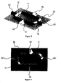
- FIG. 1 is a perspective view showing a metal membrane panel according to the present invention
- FIG. 2 is a top plan view of the metal membrane panel of FIG. 1 ;
- FIG. 3 is an enlarged perspective view of the metal membrane panel of FIG. 1 ;
- FIG. 4 is an enlarged top plan view of the metal membrane panel of FIG. 3 ;
- FIG. 5 is an enlarged top plan view showing a connecting corrugation section of the metal membrane panel according to the present invention.
- FIG. 6 is a cross-sectional view of the metal membrane panel according to the present invention.
- FIG. 7 is a perspective view of the metal membrane panel according to the present invention, which is attached on a plywood;
- FIG. 8 is a view showing a result of an elastic stress analysis of the metal m embrane panel according to the present invention.
- FIG. 9 is a perspective view showing a conventional metal membrane panel.
- FIG. 1 is a perspective view showing a metal membrane panel according to the present invention
- FIG. 2 is a top plan view of the metal membrane panel of FIG. 1
- FIG. 3 is an enlarged perspective view of the metal membrane panel of FIG. 1
- FIG. 4 is an enlarged top plan view of the metal membrane panel of FIG. 3
- FIG. 5 is an enlarged top plan view showing a connecting corrugation section of the metal membrane panel according to the present invention
- FIG. 6 is a cross-sectional view of the metal membrane panel according to the present invention
- FIG. 7 is a perspective view of the metal membrane panel according to the present invention, which is attached on a plywood.
- the metal membrane panel "A" includes a plurality of rectangular unit corrugations 10 which enable low stress regions to be formed on inside and outside thereof, and a plurality of transverse corrugations 20 and a plurality of longitudinal corrugations 30, which serves to connect the plurality of unit corrugations 10 to each other.
- Each of the unit corrugations 10 is comprised of combination of longitudinal bulging portion 11 and transverse bulging portion 12 such that the longitudinal and transverse bulging portions 11 and 12 defines a rectangular bulging strip, as viewed from plan view, which is gently rounded at corners thereof.
- the unit corrugations 10 are arranged to be spaced from each other by predetermined intervals.
- the corners of the unit corrugations 10, at which the longitudinal bulging portions 11 are connected to the transverse bulging portions 12, are gently curved, so as to disperse and alleviate stress concentrating on the corners and to allow an easy operation of manufacturing the metal membrane panel "A".
- the unit corrugations 10 are constructed such that the unit corrugations 10 are positioned at points where the transverse corrugations 20 intersect the longitudinal corrugations 30. Consequently, low stress regions are formed inside and outside the unit corrugations 10. More specifically, since an inside area of the unit corrugation 10 is smoothly curved at corners thereof, thereby defining a closed curve, the unit corrugation 10 enables a low stress to be distributed on the inside and outside areas thereof, which is equal to or less than 1/5 of the maximum stress which may otherwise occur at the intersection of the transverse and longitudinal corrugations 20 and 30.
- the transverse and longitudinal corrugations 20 and 30 are comprised of transverse and longitudinal connecting corrugation sections 40 and 50, which are adapted to connect adjacent unit corrugations to each other, and transverse and longitudinal extending corrugation sections 60 and 60', which are extended to edges of the metal membrane panel "A" from the longitudinal and transverse bulging portions 11 and 12 of the outermost unit corrugations 10 which are positioned adjacent to the edges of the metal membrane panel "A", respectively.
- transverse and longitudinal connecting corrugation sections 40 and 50 and the transverse and longitudinal extending corrugation sections 60 and 60' are arranged such that the transverse connecting corrugation sections 40 are aligned with the transverse extending corrugation sections 60 and the longitudinal connecting corrugation sections 50 are aligned with the longitudinal extending corrugation sections 60'.
- the unit corrugations 10, which has low stress regions on inside and outside areas thereof, are provided at points where the transverse and longitudinal corrugations 20 and 30 intersect, a spacing between the adjacent transverse extending corrugation sections 60 and a spacing between the adjacent longitudinal extending corrugation sections 60' are increased. Consequently, the number of the extending corrugation sections 60 and 60' formed on welding edges of the metal membrane panel "A" is reduced to about 1/2 of the number of the corresponding corrugations of a conventional metal membrane panel, thereby enabling easy application of an automatic welding.
- the unit corrugations 10, the transverse and longitudinal connecting corrugation sections 40 and 50, and the transverse and longitudinal extending corrugation sections 60 and 60' are shaped to have any of semicircular, elliptical and parabolic sections, and portions where the unit corrugations 10, the transverse and longitudinal connecting corrugation sections 40 and 50, and the transverse and longitudinal extending corrugation sections 60 and 60' are connected to a flat surface of the metal membrane panel "A" are shaped to have a concave-curved section.
- the transverse and longitudinal connecting corrugation sections 40 and 50 and the transverse and longitudinal extending corrugation sections 60 and 60' are continuously increased toward junction portions 13 where the transverse and longitudinal connecting corrugation sections 40 and 50 and the transverse and longitudinal extending corrugation sections 60 and 60' are connected to the unit corrugations 10. Accordingly, the transverse and longitudinal connecting corrugation sections 40 and 50 and the transverse and longitudinal extending corrugation sections 60 and 60' are shaped to have curved lines at the junction portions, as viewed from above, thereby preventing localized stress concentration and improving a workability of the metal membrane panel "A".
- the transverse and longitudinal connecting corrugation sections 40 and 50 are increased in width from the centers thereof toward the junction portions while forming gently curved outlines at the junction portions, and the transverse and longitudinal extending corrugation sections 60 and 60' are also increased in width from the edges of the metal membrane panel "A" toward the junction portions, as shown in FIG. 5 .
- the metal membrane panel "A” which is constructed in the above-described manner, is attached to an insulated wall to constitute an internal surface of an insulated LNG cargo tank.
- the metal membrane panel “A” is placed on a plywood 70 such that the metal membrane panel “A” is positioned at metal attaching strips 71 which are arranged on the plywood 70 into a lattice pattern, as shown in FIG. 7 .
- the metal membrane panel “A” is joined to other adjacent metal membrane panels "A” by lap welding, thereby constructing a sealed wall.
- the metal membrane panels "A", which placed on the plywood 70 are joined to each other by intermittent welding without additional joining devices, and then the resulting metal membrane panels "A” are attached to an insulated cargo tank.
- FIG. 8 shows a result of an elastic stress analysis of the metal membrane panel according to the present invention.
- an MSC/NASTRAN program is used, and an SUS304L stainless panel having a size length 3m x width 1m is used.
- FIG. 8 shows stress variations at various positions according to temperature variations from a roan temperature to -162°C As seen in FIG. 8 , curved and connected portions of the metal membrane panel exhibit the maximum stress while flat surface areas of the metal membrane panel exhibit relatively low stress.
- the present invention provides a metal membrane panel of an insulated LNG cargo tank, in which a plurality of unit rectangular corrugations, which are shaped to have curved corners, are arranged on the metal membrane panel at predetermined intervals such that the unit rectangular corrugations are positioned at intersections of transverse and longitudinal corrugations and connected to them, and junctions of the unit corrugations and the transverse and longitudinal corrugations are shaped to have gently curved outlines, so as to alleviate stress concentration acting on the transverse and longitudinal corrugations and to facilitate a manufacturing operation of the metal membrane panel. Consequently, an insulated cargo tank, which is achieved by combination of the metal membrane panels, is improved in reliability. Furthermore, since the number of corrugations formed on edge areas of the metal membrane panels to be welded is decreased, weldability is improved during a welding process.
Landscapes
- Engineering & Computer Science (AREA)
- Mechanical Engineering (AREA)
- General Engineering & Computer Science (AREA)
- Filling Or Discharging Of Gas Storage Vessels (AREA)
Description
- The present invention relates to a metal membrane panel of an insulated LNG cargo tank, and, more particularly, to a metal membrane panel of an insulated LNG cargo tank, which includes a plurality of rectangular unit corrugations formed thereon, and transverse and longitudinal connecting corrugations which connect the rectangular unit corrugations to each other, so as to alleviate localized stress concentrations, and thus, to improve a functional stability.
- Document
JP-A-55 082898 - Document
JP-A-55 078895 - Generally, LNG is extremely cold liquid having a boiling point of -162 °C, and is stored in an insulated cargo tank having a multiple wall structure. To safely store LNG having a boiling point of -162 °C, the insulated cargo tank is comprised of an internal tank wall made of a metal membrane panel and an externally insulated wall surrounding the internal tank wall. By such a multiple wall configuration, it is possible to minimize an amount of vaporized gas due to heat infiltrated into the tank from the outside.
- Since the metal membrane panel comes into close contact with LNG in an extremely cold state, the metal membrane panel is made of metal material, such as aluminum alloy, Invar, and 9% nickel steel, which are considerably reduced in a low temperature brittleness to resist distortion due to heat shrinkage. Furthermore, the metal membrane panel includes a plurality of linear corrugations such that the metal membrane panel easily expands and contracts according to repetitive temperature variations and load variations of stored liquid.
- As shown in
FIG. 9 , a conventional metal membrane panel is shaped in a rectangular form by a thin metal plate, and is provided throughout area thereof with a plurality of longitudinal and transverse linear corrugations, to allow for the expansion and contraction according to variations in temperature and load. An inner wall of a conventional insulated LNG cargo tank is typically constructed by a plurality of such metal membrane panels. In an operation of coupling the metal membrane panels to each other, respective metal membrane panels are first overlapped at four edges thereof with edges of other adjacent metal membrane panels, and the overlapped edges of the metal membrane panels are welded by lap welding, thereby providing the resulting tank with airtightness. - Such a conventional metal membrane panel is constructed in such a way that a plurality of longitudinal linear corrugations and a plurality of transverse linear corrugations are crossed to form a plurality of intersections on the metal membrane panel. Since each of the intersections is provided with curved surfaces which have a radius of curvature smaller than that of curved surfaces of the longitudinal and transverse linear corrugations, the intersections are easily subjected to a stress concentration. Furthermore, since the metal membrane panel has a relatively complicated configuration, an operation of constructing the metal membrane panel requires increased working time and processing stages, thereby causing the production of the metal membrane panel to be costly. Further, when performing an operation of joining adjacent metal membrane panels to each other by lap welding, the large number of curved portions on a welding line of the metal membrane panel causes a welding efficiency to be lowered.
- Accordingly, the present invention has been made keeping in mind the above problems occurring in the prior art, and an object of the present invention is to provide a metal membrane panel of an insulated LNG cargo tank, which is improved in a stability in terms of stress by decreasing localized stress concentration areas, and which is also improved in a welding efficiency by reducing the number of corrugations on overlapped welding edges of an adjacent metal membrane panel to reduce the number of curved portions to be welded.
- In order to accomplish the above object, the present invention provides a metal membrane panel of an insulated LNG cargo tank, which includes a plurality of rectangular unit corrugations arranged on the panel to be spaced from each other by predetermined intervals, each of the plurality of rectangular unit corrugations being comprised of a pair of transverse bulging portions and a pair of longitudinal bulging portions and being shaped to have gently curved corners, transverse and longitudinal connecting corrugations, which connect the plurality of rectangular unit corrugations to each other, and transverse and longitudinal extending corrugation, which are extended to the edges of the metal membrane panel from the transverse and longitudinal bulging portions of the outermost unit corrugations which are positioned adjacent to the edges of the metal membrane panel.
- The transverse and longitudinal connecting corrugations may be increased in width from the centers thereof toward the unit corrugations, and the transverse and longitudinal extending corrugations may be increased in width from the edges of the metal membrane panel toward the unit corrugations.
- The unit corrugations, the transverse and longitudinal connecting corrugations, and the transverse and longitudinal extending corrugations may be shaped to have any of semicircular, elliptical and parabolic sections, and portions where the unit corrugations, the transverse and longitudinal connecting corrugations, and the transverse and longitudinal extending corrugations are connected to a flat surface of the metal membrane panel may be shaped to have a concave-curved section.
- The above and other objects, features and other advantages of the present invention will be more clearly understood from the following detailed description taken in conjunction with the accompanying drawings, in which:
-
FIG. 1 is a perspective view showing a metal membrane panel according to the present invention; -
FIG. 2 is a top plan view of the metal membrane panel ofFIG. 1 ; -
FIG. 3 is an enlarged perspective view of the metal membrane panel ofFIG. 1 ; -
FIG. 4 is an enlarged top plan view of the metal membrane panel ofFIG. 3 ; -
FIG. 5 is an enlarged top plan view showing a connecting corrugation section of the metal membrane panel according to the present invention; -
FIG. 6 is a cross-sectional view of the metal membrane panel according to the present invention; -
FIG. 7 is a perspective view of the metal membrane panel according to the present invention, which is attached on a plywood; -
FIG. 8 is a view showing a result of an elastic stress analysis of the metal m embrane panel according to the present invention; and -
FIG. 9 is a perspective view showing a conventional metal membrane panel. - This invention will be described in further detail by way of example with reference to the accompanying drawings.
-
FIG. 1 is a perspective view showing a metal membrane panel according to the present invention,FIG. 2 is a top plan view of the metal membrane panel ofFIG. 1 ,FIG. 3 is an enlarged perspective view of the metal membrane panel ofFIG. 1 ,FIG. 4 is an enlarged top plan view of the metal membrane panel ofFIG. 3 ,FIG. 5 is an enlarged top plan view showing a connecting corrugation section of the metal membrane panel according to the present invention,FIG. 6 is a cross-sectional view of the metal membrane panel according to the present invention, andFIG. 7 is a perspective view of the metal membrane panel according to the present invention, which is attached on a plywood. - As showing in the drawings, the metal membrane panel "A" according to the present invention includes a plurality of
rectangular unit corrugations 10 which enable low stress regions to be formed on inside and outside thereof, and a plurality oftransverse corrugations 20 and a plurality oflongitudinal corrugations 30, which serves to connect the plurality ofunit corrugations 10 to each other. - Each of the
unit corrugations 10 is comprised of combination of longitudinal bulgingportion 11 and transverse bulgingportion 12 such that the longitudinal and transverse bulgingportions unit corrugations 10 are arranged to be spaced from each other by predetermined intervals. As mentioned above, the corners of theunit corrugations 10, at which the longitudinal bulgingportions 11 are connected to the transverse bulgingportions 12, are gently curved, so as to disperse and alleviate stress concentrating on the corners and to allow an easy operation of manufacturing the metal membrane panel "A". - The
unit corrugations 10 are constructed such that theunit corrugations 10 are positioned at points where thetransverse corrugations 20 intersect thelongitudinal corrugations 30. Consequently, low stress regions are formed inside and outside theunit corrugations 10. More specifically, since an inside area of theunit corrugation 10 is smoothly curved at corners thereof, thereby defining a closed curve, theunit corrugation 10 enables a low stress to be distributed on the inside and outside areas thereof, which is equal to or less than 1/5 of the maximum stress which may otherwise occur at the intersection of the transverse andlongitudinal corrugations - The transverse and
longitudinal corrugations corrugation sections corrugation sections 60 and 60', which are extended to edges of the metal membrane panel "A" from the longitudinal and transverse bulgingportions outermost unit corrugations 10 which are positioned adjacent to the edges of the metal membrane panel "A", respectively. In this configuration, the transverse and longitudinal connectingcorrugation sections corrugation sections 60 and 60' are arranged such that the transverse connectingcorrugation sections 40 are aligned with the transverse extendingcorrugation sections 60 and the longitudinal connectingcorrugation sections 50 are aligned with the longitudinal extending corrugation sections 60'. - According to the present invention, since the
unit corrugations 10, which has low stress regions on inside and outside areas thereof, are provided at points where the transverse andlongitudinal corrugations corrugation sections 60 and a spacing between the adjacent longitudinal extending corrugation sections 60' are increased. Consequently, the number of the extendingcorrugation sections 60 and 60' formed on welding edges of the metal membrane panel "A" is reduced to about 1/2 of the number of the corresponding corrugations of a conventional metal membrane panel, thereby enabling easy application of an automatic welding. - As shown in
FIG. 6 , theunit corrugations 10, the transverse and longitudinal connectingcorrugation sections corrugation sections 60 and 60' are shaped to have any of semicircular, elliptical and parabolic sections, and portions where theunit corrugations 10, the transverse and longitudinal connectingcorrugation sections corrugation sections 60 and 60' are connected to a flat surface of the metal membrane panel "A" are shaped to have a concave-curved section. - Widths of the transverse and longitudinal connecting
corrugation sections corrugation sections 60 and 60' are continuously increased towardjunction portions 13 where the transverse and longitudinal connectingcorrugation sections corrugation sections 60 and 60' are connected to theunit corrugations 10. Accordingly, the transverse and longitudinal connectingcorrugation sections corrugation sections 60 and 60' are shaped to have curved lines at the junction portions, as viewed from above, thereby preventing localized stress concentration and improving a workability of the metal membrane panel "A". In other words, the transverse and longitudinal connectingcorrugation sections corrugation sections 60 and 60' are also increased in width from the edges of the metal membrane panel "A" toward the junction portions, as shown inFIG. 5 . - In application, the metal membrane panel "A" according to the present invention, which is constructed in the above-described manner, is attached to an insulated wall to constitute an internal surface of an insulated LNG cargo tank. At this point, the metal membrane panel "A" is placed on a
plywood 70 such that the metal membrane panel "A" is positioned atmetal attaching strips 71 which are arranged on theplywood 70 into a lattice pattern, as shown inFIG. 7 . The metal membrane panel "A" is joined to other adjacent metal membrane panels "A" by lap welding, thereby constructing a sealed wall. At this time, the metal membrane panels "A", which placed on theplywood 70, are joined to each other by intermittent welding without additional joining devices, and then the resulting metal membrane panels "A" are attached to an insulated cargo tank. -
FIG. 8 shows a result of an elastic stress analysis of the metal membrane panel according to the present invention. In performing this elastic stress analysis, an MSC/NASTRAN program is used, and an SUS304L stainless panel having a size length 3m x width 1m is used.FIG. 8 shows stress variations at various positions according to temperature variations from a roan temperature to -162°C As seen inFIG. 8 , curved and connected portions of the metal membrane panel exhibit the maximum stress while flat surface areas of the metal membrane panel exhibit relatively low stress. - As described above, the present invention provides a metal membrane panel of an insulated LNG cargo tank, in which a plurality of unit rectangular corrugations, which are shaped to have curved corners, are arranged on the metal membrane panel at predetermined intervals such that the unit rectangular corrugations are positioned at intersections of transverse and longitudinal corrugations and connected to them, and junctions of the unit corrugations and the transverse and longitudinal corrugations are shaped to have gently curved outlines, so as to alleviate stress concentration acting on the transverse and longitudinal corrugations and to facilitate a manufacturing operation of the metal membrane panel. Consequently, an insulated cargo tank, which is achieved by combination of the metal membrane panels, is improved in reliability. Furthermore, since the number of corrugations formed on edge areas of the metal membrane panels to be welded is decreased, weldability is improved during a welding process.
Claims (3)
- A metal membrane panel (A) of an insulated LNG cargo tank, comprising:a plurality of rectangular unit corrugations (10) arranged on the panel to be spaced from each other by predetermined intervals, each of the plurality of rectangular unit corrugations (10) being comprised of a pair of transverse bulging portions (12) and a pair of longitudinal bulging portions (11) and being shaped to have gently curved comers;transverse and longitudinal connecting corrugations (40, 50), which connect the plurality of rectangular unit corrugations (10) to each other; andtransverse and longitudinal extending corrugations (60, 60'), which are extended to edges of the metal membrane panel (A) from the transverse and longitudinal bulging portions (12, 11) of the outermost unit corrugations which are positioned adjacent to the edges of the metal membrane panel (A).
- The metal membrane panel (A) as set forth in claim 1, wherein the transverse and longitudinal connecting corrugations (40, 50) are increased in width from the centers thereof toward the unit corrugations (10), and the transverse and longitudinal extending corrugations (60, 60') are increased in width from the edges of the metal membrane panel (A) toward the unit corrugations (10).
- The metal membrane panel (A) as set forth in claim 1 or 2, wherein the unit corrugations (10), the transverse and longitudinal connecting corrugations (40, 50), and the transverse and longitudinal extending corrugations (60, 60') are shaped to have any of semicircular, elliptical and parabolic sections, and portions where the unit corrugations (10), the transverse and longitudinal connecting corrugations (40, 50), and the transverse and longitudinal extending corrugations (60, 60') are connected to a flat surface of the metal membrane panel (A) are shaped to have a concave-curved section.
Applications Claiming Priority (2)
| Application Number | Priority Date | Filing Date | Title |
|---|---|---|---|
| KR1020040021526A KR100707675B1 (en) | 2004-03-30 | 2004-03-30 | Membrane Metal Panels for LAN Storage Tanks |
| PCT/KR2004/003028 WO2005095234A1 (en) | 2004-03-30 | 2004-11-23 | Metal membrane panel of insulated lng cargo tank |
Publications (3)
| Publication Number | Publication Date |
|---|---|
| EP1732828A1 EP1732828A1 (en) | 2006-12-20 |
| EP1732828A4 EP1732828A4 (en) | 2008-03-26 |
| EP1732828B1 true EP1732828B1 (en) | 2010-02-10 |
Family
ID=35063646
Family Applications (1)
| Application Number | Title | Priority Date | Filing Date |
|---|---|---|---|
| EP04808205A Expired - Fee Related EP1732828B1 (en) | 2004-03-30 | 2004-11-23 | Metal membrane panel of insulated lng cargo tank |
Country Status (4)
| Country | Link |
|---|---|
| EP (1) | EP1732828B1 (en) |
| JP (1) | JP4564051B2 (en) |
| KR (1) | KR100707675B1 (en) |
| WO (1) | WO2005095234A1 (en) |
Families Citing this family (4)
| Publication number | Priority date | Publication date | Assignee | Title |
|---|---|---|---|---|
| KR102201249B1 (en) * | 2013-09-06 | 2021-01-11 | 대우조선해양 주식회사 | Membrane panel of membrane type tank for cryogenic fluid storage |
| CN112145954B (en) * | 2020-09-21 | 2022-04-26 | 浙江振申绝热科技股份有限公司 | Tank bottom structure of metal inner tank of membrane type low-temperature storage tank |
| CN117190057B (en) * | 2023-09-12 | 2025-09-12 | 沪东中华造船(集团)有限公司 | Sealing film, tank body and manufacturing method of low-temperature liquefied gas sealed insulation storage tank |
| CN117718755B (en) * | 2024-02-18 | 2024-06-21 | 中太能源科技(上海)有限公司 | Processing system of metal plate |
Family Cites Families (10)
| Publication number | Priority date | Publication date | Assignee | Title |
|---|---|---|---|---|
| NL297976A (en) * | 1963-05-06 | |||
| DE1450432B2 (en) | 1963-06-27 | 1976-01-08 | Technigaz S.A., Paris | Developable expansion wall for a container |
| JPS4111104Y1 (en) * | 1965-08-02 | 1966-05-24 | ||
| JPS4935060U (en) * | 1972-06-28 | 1974-03-28 | ||
| JPS5578895A (en) * | 1978-12-12 | 1980-06-13 | Kawasaki Heavy Ind Ltd | Membrane structure of low temperature liquid tank |
| JPS5582898A (en) * | 1978-12-13 | 1980-06-21 | Kawasaki Heavy Ind Ltd | Joint structure in low temperature storage tank |
| JPS5754797A (en) * | 1980-09-12 | 1982-04-01 | Kawasaki Heavy Ind Ltd | Construction of membrane tank |
| KR970005076B1 (en) * | 1994-05-28 | 1997-04-12 | 한국가스공사 | Membrane Structure for LNG Tank and Manufacturing Method |
| FR2735847B1 (en) * | 1995-06-22 | 1997-08-14 | Korea Gas Corp | MEMBRANE FOR LIQUEFIED NATURAL GAS STORAGE TANK |
| KR100213686B1 (en) * | 1997-01-30 | 1999-09-01 | 이해규 | Membrane Corrugation Structure of Low Temperature Liquid Storage Tank |
-
2004
- 2004-03-30 KR KR1020040021526A patent/KR100707675B1/en not_active Expired - Fee Related
- 2004-11-23 JP JP2007506068A patent/JP4564051B2/en not_active Expired - Fee Related
- 2004-11-23 EP EP04808205A patent/EP1732828B1/en not_active Expired - Fee Related
- 2004-11-23 WO PCT/KR2004/003028 patent/WO2005095234A1/en not_active Ceased
Also Published As
| Publication number | Publication date |
|---|---|
| JP4564051B2 (en) | 2010-10-20 |
| JP2007530892A (en) | 2007-11-01 |
| EP1732828A4 (en) | 2008-03-26 |
| EP1732828A1 (en) | 2006-12-20 |
| WO2005095234A1 (en) | 2005-10-13 |
| KR100707675B1 (en) | 2007-04-13 |
| KR20050096357A (en) | 2005-10-06 |
Similar Documents
| Publication | Publication Date | Title |
|---|---|---|
| KR101722377B1 (en) | Sealed and insulating vessel comprising a support foot | |
| EP0486276A1 (en) | Carrier for automobile exhaust gas purifying catalyst | |
| KR101205369B1 (en) | Membrane panel for a liquid storage tank | |
| KR101556259B1 (en) | Membrane of cargo for liquefied gas | |
| KR101732621B1 (en) | Membrane of cargo, cargo including same and manufacturing method thereof | |
| KR970005076B1 (en) | Membrane Structure for LNG Tank and Manufacturing Method | |
| KR102033536B1 (en) | Strake-end connection structure of lng carrier cargo tank | |
| EP1732828A1 (en) | Metal membrane panel of insulated lng cargo tank | |
| KR20100022679A (en) | Angle pieces for mounted on corner panel of lng cargo containment system | |
| KR20200082579A (en) | Mebrane of cryogenic fluid storage tank | |
| CN1965205B (en) | Distillation tower | |
| US3994693A (en) | Expandable metal membrane | |
| CN118463014A (en) | Film shell structure of low-temperature storage tank | |
| KR102897565B1 (en) | Metal membrane for liquefied gas storage tank | |
| KR100781031B1 (en) | Membrane metal panel of thermal insulation tank for LAN carriers with excellent durability and welding workability | |
| WO2025055424A1 (en) | Low-temperature-resistant sealing film for covering insulating material, storage tank and manufacturing method | |
| KR20050078789A (en) | Membrane metal panel with flat welding joint part for insulated cargo tanks of lng carrier | |
| KR20200026557A (en) | Insulation structure of membrane type strorage tank | |
| KR100750489B1 (en) | Membrane metal panel of low temperature liquid storage tank with welded surface | |
| KR970005077B1 (en) | Membrane Structure for LNG Tanks | |
| CN117799771A (en) | Heat insulation supporting film component of semi-film cargo containment system and application mode thereof | |
| KR20200031417A (en) | Anchorstrip and panel assembly for lng cargo including same | |
| JPS6246759B2 (en) | ||
| KR20050060590A (en) | Membrane metal panel of insulated lng tank | |
| JPH09236200A (en) | Membrane structure for liquefied natural gas storage tank |
Legal Events
| Date | Code | Title | Description |
|---|---|---|---|
| PUAI | Public reference made under article 153(3) epc to a published international application that has entered the european phase |
Free format text: ORIGINAL CODE: 0009012 |
|
| 17P | Request for examination filed |
Effective date: 20061030 |
|
| AK | Designated contracting states |
Kind code of ref document: A1 Designated state(s): FR |
|
| DAX | Request for extension of the european patent (deleted) | ||
| RBV | Designated contracting states (corrected) |
Designated state(s): FR |
|
| A4 | Supplementary search report drawn up and despatched |
Effective date: 20080227 |
|
| 17Q | First examination report despatched |
Effective date: 20080701 |
|
| GRAP | Despatch of communication of intention to grant a patent |
Free format text: ORIGINAL CODE: EPIDOSNIGR1 |
|
| GRAS | Grant fee paid |
Free format text: ORIGINAL CODE: EPIDOSNIGR3 |
|
| GRAA | (expected) grant |
Free format text: ORIGINAL CODE: 0009210 |
|
| AK | Designated contracting states |
Kind code of ref document: B1 Designated state(s): FR |
|
| PLBE | No opposition filed within time limit |
Free format text: ORIGINAL CODE: 0009261 |
|
| STAA | Information on the status of an ep patent application or granted ep patent |
Free format text: STATUS: NO OPPOSITION FILED WITHIN TIME LIMIT |
|
| 26N | No opposition filed |
Effective date: 20101111 |
|
| REG | Reference to a national code |
Ref country code: FR Ref legal event code: PLFP Year of fee payment: 12 |
|
| PGFP | Annual fee paid to national office [announced via postgrant information from national office to epo] |
Ref country code: FR Payment date: 20151026 Year of fee payment: 12 |
|
| REG | Reference to a national code |
Ref country code: FR Ref legal event code: ST Effective date: 20170731 |
|
| PG25 | Lapsed in a contracting state [announced via postgrant information from national office to epo] |
Ref country code: FR Free format text: LAPSE BECAUSE OF NON-PAYMENT OF DUE FEES Effective date: 20161130 |