EP1732725B1 - Pipe cutting apparatus - Google Patents
Pipe cutting apparatus Download PDFInfo
- Publication number
- EP1732725B1 EP1732725B1 EP05731361A EP05731361A EP1732725B1 EP 1732725 B1 EP1732725 B1 EP 1732725B1 EP 05731361 A EP05731361 A EP 05731361A EP 05731361 A EP05731361 A EP 05731361A EP 1732725 B1 EP1732725 B1 EP 1732725B1
- Authority
- EP
- European Patent Office
- Prior art keywords
- pipe
- cutting
- cutter head
- support rolls
- crank plate
- Prior art date
- Legal status (The legal status is an assumption and is not a legal conclusion. Google has not performed a legal analysis and makes no representation as to the accuracy of the status listed.)
- Expired - Lifetime
Links
Images


Classifications
-
- B—PERFORMING OPERATIONS; TRANSPORTING
- B23—MACHINE TOOLS; METAL-WORKING NOT OTHERWISE PROVIDED FOR
- B23D—PLANING; SLOTTING; SHEARING; BROACHING; SAWING; FILING; SCRAPING; LIKE OPERATIONS FOR WORKING METAL BY REMOVING MATERIAL, NOT OTHERWISE PROVIDED FOR
- B23D21/00—Machines or devices for shearing or cutting tubes
- B23D21/04—Tube-severing machines with rotating tool-carrier
Definitions
- the invention relates to a pipe cutting apparatus, comprising a body, a cutter head bearing-mounted rotatably on the body, having a centre rotation axis and having a cutting gap which opens radially sideways for receiving a pipe to be cut, pipe securing elements for fixing the pipe on said centre rotation axis immovably relative to the body, support rolls in the cutter head for supporting the pipe during a cutting process, and a cutting blade in the shape of a sharp-edged disk present in the cutter head, which, during rotation of the cutter head, is adapted to be advanced towards the centre rotation axis for cutting the pipe by chipless cutting.
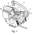
- the pipe cutting apparatus shown in fig. 1 comprises a body, which is fitted with handles 4 and 5 and on which a cutter head 1 is rotatably mounted with bearings.
- the cutter head 1 has a centre rotation axis C ( Fig. 2 ) and the cutter head 1 has a radially sideways opening cutting gap (2), through which the centre rotation axis C extends and which receives a pipe to be cut.
- the apparatus is provided with a protective cover 3, which houses the cutter head 1, closes and opens the cutting gap 2, and which is displaceable back and forth in the direction of an arrow A, whereby a handle or gripping bar 3a present at the edge of the cover 3 travels from side to side across the opening in a cutter head housing.
- the apparatus has also a service connection 6 and an operating switch 7.
- the pipe to be cut can be fixed on said centre rotation axis C by means of securing elements 8, comprising in the present case two jaws 8 which are linearly conveyable towards and away from each other with a driving screw. Accordingly, the pipe to be cut is secured immovably relative to the apparatus' body on the centre rotation axis C of the cutter head 1.
- Fig. 2 illustrates components essential with regard to the operation of a cutter head.
- the cutter head has its body 11 fitted with a slotted crank plate 12 for rotation over a limited distance around the axis C.
- the slotted crank plate 12 is provided with an arcuate guide slot 15 pivoting a swing arm 16 for a support roll 21 about an axle 18.
- a swing arm 17 for a second support roll 21 pivots therealong about an axle 20 by means of a meshed engagement 19 between the swing arms 16, 17.
- a cutting blade 22 in the shape of a sharp-edged disk is rotatably mounted with bearings on the end of a cam arm 23.
- the cam arm 23 is bearing-mounted for pivoting about an axle 23c into a blade cradle 23b.
- the cam arm 23 is only capable of pivoting about the axle 23c against the load of a spring over a limited distance relative to the blade cradle 23b. This limited distance is equal to or slightly longer than the maximum wall thickness of a pipe to be cut.
- An arcuate guide slot 23a present in the slotted crank plate 12 is designed in such a shape that, as it is turning (the cutter head body 11 and the slotted crank plate 12 pivoting relative to each other), the blade cradle 23b carries the blade 22 towards the centre axis C over a distance substantially equal to a displacement of the support rolls 21 in response to the guide slot 15.
- the blade 22 must trail slightly behind to have the support rolls 21 colliding first with the pipe surface.
- This approaching motion for the support rolls 21 and the blade 22 is created by means of a pulling device 13 engaging in a recess 14 in the slotted crank plate 12.
- the mutually responding bevel faces of the recess 14 and the pulling device 13 and the radial mobility of the pulling device 13 enable the pulling device 13 to slip off the recess 14 as the support rolls 21 collide with a pipe surface.
- the pivoting motion of the slotted crank plate 12 stops automatically whenever the support rolls 21 collide with a pipe surface, i.e. approaching and stopping of the motion are effected automatically with a single drive and/or control, regardless of the diameter of a pipe.
- the pulling device 13 is preferably linked with a displacement A of the protective cover 3, such that the displacement of the protective cover 3 in one direction carries the support rolls 21 and the cutting blade 22 to a cutting-ready position and the displacement A in the opposite direction returns the support rolls 21 and the cutting blade 22 to a home position.
- the pulling device 13 upon opening the cover 3, the pulling device 13 becomes a pushing device which falls into the recess 14 and returns the slotted crank plate 12 with respect to the body 11 across a distance A'.
- the side of an elongated hole present in the slotted crank plate 12 is provided with a toothed arc 28 which is in meshed engagement with a gear 31 mounted on a crank plate shaft 30 extended through an opening 29 in the body 11.
- the toothed arc 28 rotates the crank plate shaft 30 as the slotted crank plate 12 is pivoted relative to the body 11 for conveying the support rolls 21 against a pipe surface.
- a freewheel clutch 32 Around the crank plate shaft 30 is a freewheel clutch 32, allowing rotation of the crank plate shaft 30 in one direction, yet blocking rotation in the opposite direction.
- the crank plate shaft 30 and the freewheel clutch 32 function to lock the slotted crank plate 12 in any position at which the support rolls 21 collide with a pipe surface.
- the crank plate shaft 30 In order to enable returning the support rolls 21 and the blade 22 to a home position after a pipe cutting process described hereinafter, the crank plate shaft 30 must be released for rotation in both directions.
- the freewheel clutch 32 is encircled with a cylinder 33, its outer surface being provided with recesses 34 around its periphery, any one of these being able to receive a locking ball 35 present in a hole at a stationary cylinder 37a.
- the cylinder 37a houses a piston 37 held by a spring 38 in a position which blocks the escape of the locking ball 35 from the recess 34.
- the piston 37 has its pin 39 received in a bevel-faced groove in a release plate 40.
- shifting mechanism 12-20 and locking mechanism 28-40 for the support rolls 21. It is indeed essential in the invention that a single drive and/or control can be used for shifting and locking support rolls against the surface of pipes with varying diameters as this has previously required an individual setting for every pipe diameter.
Landscapes
- Engineering & Computer Science (AREA)
- Mechanical Engineering (AREA)
- Sawing (AREA)
- Rigid Pipes And Flexible Pipes (AREA)
- Accessories And Tools For Shearing Machines (AREA)
Abstract
Description
- The invention relates to a pipe cutting apparatus, comprising a body, a cutter head bearing-mounted rotatably on the body, having a centre rotation axis and having a cutting gap which opens radially sideways for receiving a pipe to be cut, pipe securing elements for fixing the pipe on said centre rotation axis immovably relative to the body, support rolls in the cutter head for supporting the pipe during a cutting process, and a cutting blade in the shape of a sharp-edged disk present in the cutter head, which, during rotation of the cutter head, is adapted to be advanced towards the centre rotation axis for cutting the pipe by chipless cutting.
- This type of pipe cutting devices are known e.g. from patent publications
US-4,111,346 andUS-6,065,212 . The latter comprises two concentric gears adapted for relative rotation, and a cutting blade is mounted on one of the gears. Both the cutting blade and support rolls must be conveyed by means of a separate motor drive to a cutting position and returned to a home position by means of a reversed motor drive. This hampers and complicates operation of the apparatus. - It is an object of the invention to provide an improved pipe cutting apparatus, wherein support rolls are shifted and locked with a single drive and/or control, regardless of a pipe diameter, against the pipe surface for cutting support. This object is achieved on the basis of characterizing features of the invention as set forth in the appended
claim 1. A more detailed implementation for a preferred exemplary embodiment of the invention is set forth in the dependent claims. - One exemplary embodiment of the invention will now be described in more detail with reference to the accompanying drawings, in which
- Fig. 1
- shows a pipe cutting apparatus of the invention as a portable tool,
- Fig. 2
- shows an essential part of a
cutter head 1 in the pipe cutting apparatus as seen in axial direction, - Fig. 3
- shows a part of the cutter head of the pipe cutting apparatus in section,
- Figs. 4-6
- show the cutter head of
fig. 2 in various positions of its components in a cutting-ready position with various pipe diameters, and - Fig. 7
- shows the cutter head of
fig. 2 with the support rolls and the cutting blade in a home position. - The pipe cutting apparatus shown in
fig. 1 comprises a body, which is fitted withhandles cutter head 1 is rotatably mounted with bearings. Thecutter head 1 has a centre rotation axis C (Fig. 2 ) and thecutter head 1 has a radially sideways opening cutting gap (2), through which the centre rotation axis C extends and which receives a pipe to be cut. - The apparatus is provided with a
protective cover 3, which houses thecutter head 1, closes and opens thecutting gap 2, and which is displaceable back and forth in the direction of an arrow A, whereby a handle or grippingbar 3a present at the edge of thecover 3 travels from side to side across the opening in a cutter head housing. The apparatus has also a service connection 6 and anoperating switch 7. - The pipe to be cut can be fixed on said centre rotation axis C by means of securing
elements 8, comprising in the present case twojaws 8 which are linearly conveyable towards and away from each other with a driving screw. Accordingly, the pipe to be cut is secured immovably relative to the apparatus' body on the centre rotation axis C of thecutter head 1. -
Fig. 2 illustrates components essential with regard to the operation of a cutter head. The cutter head has itsbody 11 fitted with a slottedcrank plate 12 for rotation over a limited distance around the axis C. The slottedcrank plate 12 is provided with anarcuate guide slot 15 pivoting aswing arm 16 for asupport roll 21 about anaxle 18. Aswing arm 17 for a second support roll 21 pivots therealong about anaxle 20 by means of ameshed engagement 19 between theswing arms cutting blade 22 in the shape of a sharp-edged disk is rotatably mounted with bearings on the end of acam arm 23. Thecam arm 23 is bearing-mounted for pivoting about anaxle 23c into ablade cradle 23b. Thecam arm 23 is only capable of pivoting about theaxle 23c against the load of a spring over a limited distance relative to theblade cradle 23b. This limited distance is equal to or slightly longer than the maximum wall thickness of a pipe to be cut. Anarcuate guide slot 23a present in theslotted crank plate 12 is designed in such a shape that, as it is turning (thecutter head body 11 and the slottedcrank plate 12 pivoting relative to each other), theblade cradle 23b carries theblade 22 towards the centre axis C over a distance substantially equal to a displacement of thesupport rolls 21 in response to theguide slot 15. Theblade 22 must trail slightly behind to have thesupport rolls 21 colliding first with the pipe surface. - This approaching motion for the
support rolls 21 and theblade 22 is created by means of apulling device 13 engaging in arecess 14 in the slottedcrank plate 12. The mutually responding bevel faces of therecess 14 and thepulling device 13 and the radial mobility of thepulling device 13 enable thepulling device 13 to slip off therecess 14 as thesupport rolls 21 collide with a pipe surface. Thus, the pivoting motion of the slottedcrank plate 12 stops automatically whenever the support rolls 21 collide with a pipe surface, i.e. approaching and stopping of the motion are effected automatically with a single drive and/or control, regardless of the diameter of a pipe. In the presently described manually operated cutting apparatus, thepulling device 13 is preferably linked with a displacement A of theprotective cover 3, such that the displacement of theprotective cover 3 in one direction carries thesupport rolls 21 and thecutting blade 22 to a cutting-ready position and the displacement A in the opposite direction returns thesupport rolls 21 and thecutting blade 22 to a home position. Thus, upon opening thecover 3, thepulling device 13 becomes a pushing device which falls into therecess 14 and returns the slottedcrank plate 12 with respect to thebody 11 across a distance A'. - In reference to
figs. 2 and3 , there will now be explained how the support rolls 21 also automatically lock themselves in any displaced position when bearing against the surface of pipes with varying diameters. The side of an elongated hole present in the slottedcrank plate 12 is provided with atoothed arc 28 which is in meshed engagement with agear 31 mounted on acrank plate shaft 30 extended through anopening 29 in thebody 11. Hence, thetoothed arc 28 rotates thecrank plate shaft 30 as the slottedcrank plate 12 is pivoted relative to thebody 11 for conveying thesupport rolls 21 against a pipe surface. Around thecrank plate shaft 30 is afreewheel clutch 32, allowing rotation of thecrank plate shaft 30 in one direction, yet blocking rotation in the opposite direction. Thus, thecrank plate shaft 30 and thefreewheel clutch 32 function to lock the slottedcrank plate 12 in any position at which the support rolls 21 collide with a pipe surface. - In order to enable returning the
support rolls 21 and theblade 22 to a home position after a pipe cutting process described hereinafter, thecrank plate shaft 30 must be released for rotation in both directions. In the presently depicted exemplary embodiment, thefreewheel clutch 32 is encircled with acylinder 33, its outer surface being provided withrecesses 34 around its periphery, any one of these being able to receive alocking ball 35 present in a hole at astationary cylinder 37a. Thecylinder 37a houses apiston 37 held by aspring 38 in a position which blocks the escape of thelocking ball 35 from therecess 34. Thepiston 37 has itspin 39 received in a bevel-faced groove in arelease plate 40. In response to turning therelease plate 40, thepiston 37 is pushed by thepin 39 to a position which allows thelocking ball 35 to enter arecess 36, whereby thecrank plate shaft 30 is able to rotate in both directions. The turning motion of therelease plate 40 can also be transmitted from the opening motion of thecover 3 by means of an appropriate linkage which releases thecrank plate shaft 30 for rotation before the pulling and pushingdevice 13 falls into therecess 14 for rotating the slottedcrank plate 12 to a home position (arrow A'). Infig. 3 ,reference numerals cutter head 1. - In reference to
fig. 2 , there is still described an advancement of theblade 22 during a cutting operation. Once thesupport rolls 21 have been brought, as described above, to a cutting-ready position, rotation of thecutter head 1 is started by means of theoperating switch 7. Alongside the cutter head is astar pinion 26 which, upon colliding with a detent 27, rotates over one point in every cycle of the cutter head. Thestar pinion 26 has a screw on its axis for slowly rotating aspindle 24 of acam wheel 25, whereby thecam arm 23 is gradually pivoted by thecam wheel 25 about theaxle 23c for advancing theblade 22 towards the centre axis C. Thus, thecam arm 23 pivots against a spring load across the above-mentioned limited distance with respect to theblade cradle 23b. - There are many structural options for implementing the above described shifting mechanism 12-20 and locking mechanism 28-40 for the
support rolls 21. It is indeed essential in the invention that a single drive and/or control can be used for shifting and locking support rolls against the surface of pipes with varying diameters as this has previously required an individual setting for every pipe diameter.
Claims (4)
- A pipe cutting apparatus, comprising a body, a cutter head (1) bearing-mounted rotatably on the body, having a centre rotation axis (C) and having a cutting gap (2) which opens radially sideways for receiving a pipe to be cut, pipe securing elements (8) for fixing the pipe on said centre rotation axis (C) immovably relative to the body, support rolls (21) in the cutter head (1) for supporting the pipe during a cutting process, and a cutting blade (22) in the shape of a sharp-edged disk present in the cutter head (1), which, during rotation of the cutter head (1), is adapted to be advanced towards the centre rotation axis (C) for cutting the pipe by chipless cutting, characterized in that the cutter head (1) is provided with a shifting and locking mechanism (12-20, 28-40) for the support rolls (21), which, regardless of the diameter of a pipe to be cut, shifts and locks the support rolls (21) with a single drive and/or control against the surface of a pipe for said cutting support.
- An apparatus as set forth in claim 1, characterized in that the shifting and locking mechanism (12-20, 28-40) comprises- a slotted crank plate (12), rotatable about said rotation axis (C) relative to the cutter head (1) and including an arcuate guide slot (15) pivoting a swing arm (16) for the support roll (21),- a crank plate shaft (30), having its gear (31) meshed with a toothed arc (28) of the slotted crank plate (12) for rotating the crank plate shaft (30) as the slotted crank plate (12) is turned for shifting the support rolls (21) against the surface of a pipe,- a freewheel clutch (32) in association with the crank plate shaft (30) for allowing said rotational motion of the crank plate shaft (30), yet blocking rotational motion in the opposite direction and thereby locking the slotted crank plate (12) in any position at which the support rolls (21) collide with the surface of a pipe to be cut.
- An apparatus as set forth in claim 1 or 2, characterized in that the cutting apparatus is a portable tool with handles (4, 5), which includes a displaceable protective cover (3) that houses the cutter head (1), opens and closes the cutting gap (2) and has its displacement (A) transmitted to the shifting and locking mechanism (12-20, 28-40) of the support rolls, such that the protective cover (3) has its displacement (A) in one direction shifting the support rolls (21) and the cutting blade (22) to a cutting-ready position and its displacement (A) in the opposite direction returning the support rolls (21) and the cutting blade (22) to a home position in which the cutting gap (2) is vacant.
- An apparatus as set forth in claim 2 or 3, characterized in that the freewheel clutch (32) is encircled by a clamping mechanism (34-40) for optionally locking the freewheel clutch (32) over its outer periphery for no rotation or releasing it for rotation in both directions.
Applications Claiming Priority (2)
| Application Number | Priority Date | Filing Date | Title |
|---|---|---|---|
| FI20045103A FI117328B (en) | 2004-03-26 | 2004-03-26 | tube cutting assembly |
| PCT/FI2005/050107 WO2005092550A1 (en) | 2004-03-26 | 2005-03-24 | Pipe cutting apparatus |
Publications (2)
| Publication Number | Publication Date |
|---|---|
| EP1732725A1 EP1732725A1 (en) | 2006-12-20 |
| EP1732725B1 true EP1732725B1 (en) | 2009-05-20 |
Family
ID=32039530
Family Applications (1)
| Application Number | Title | Priority Date | Filing Date |
|---|---|---|---|
| EP05731361A Expired - Lifetime EP1732725B1 (en) | 2004-03-26 | 2005-03-24 | Pipe cutting apparatus |
Country Status (8)
| Country | Link |
|---|---|
| US (1) | US7464472B2 (en) |
| EP (1) | EP1732725B1 (en) |
| JP (1) | JP4832424B2 (en) |
| AT (1) | ATE431767T1 (en) |
| DE (1) | DE602005014551D1 (en) |
| ES (1) | ES2326180T3 (en) |
| FI (1) | FI117328B (en) |
| WO (1) | WO2005092550A1 (en) |
Families Citing this family (14)
| Publication number | Priority date | Publication date | Assignee | Title |
|---|---|---|---|---|
| DE112008000686B4 (en) * | 2007-03-15 | 2016-07-28 | Milwaukee Electric Tool Corp. | Rohrschneider |
| CN102064234B (en) * | 2010-11-01 | 2012-10-17 | 江苏永能光伏科技有限公司 | Perforating machine |
| USD653266S1 (en) * | 2011-08-02 | 2012-01-31 | Woodward Stephen W | PVC cut and bevel machine |
| CN103317180A (en) * | 2013-06-20 | 2013-09-25 | 江苏丰立精密制管有限公司 | Chipless cutting machine |
| CN205218181U (en) | 2015-06-15 | 2016-05-11 | 米沃奇电动工具公司 | Pipeline cutterbar |
| USD813006S1 (en) | 2015-06-15 | 2018-03-20 | Milwaukee Electric Tool Corporation | Knob for a cutter |
| CN105058470A (en) * | 2015-09-18 | 2015-11-18 | 南通联恒新材料有限公司 | All-in-one machine for chipless cutting of plastic pipes |
| US10052701B2 (en) * | 2015-12-16 | 2018-08-21 | Ridge Tool Company | C-type tubing cutter |
| EP3431732B1 (en) | 2017-07-21 | 2020-04-22 | Bosal Emission Control Systems NV | Method for forming a collar in a muffler housing |
| CN107984511A (en) * | 2017-11-14 | 2018-05-04 | 天津市金颐有色线材有限公司 | A kind of novel plastic particle Chipless cutting machine |
| CN109986357B (en) * | 2019-03-22 | 2023-03-28 | 佛山市天箭机械设备有限公司 | Short pipe chipless cutting machine |
| CN111590536B (en) * | 2020-05-22 | 2022-03-22 | 福建得乾集团有限责任公司 | Cutting device is used in installation of nodular cast iron pipeline |
| GB2592767B (en) * | 2021-03-24 | 2022-05-04 | Scott Cutters Ltd | Cutting tool |
| CN113319362B (en) * | 2021-07-13 | 2024-08-13 | 邱强生 | Multi-blade rotary feeding pipe cutting knife disc and pipe cutter |
Family Cites Families (13)
| Publication number | Priority date | Publication date | Assignee | Title |
|---|---|---|---|---|
| GB572217A (en) * | 1943-01-09 | 1945-09-27 | Der Eisenund Stahlwerke Ag | Improvements in or relating to pipe- and other profiled- bar cutting apparatus |
| JPS5120290A (en) * | 1974-08-10 | 1976-02-18 | Sumitomo Chemical Co | |
| US4111346A (en) * | 1977-01-11 | 1978-09-05 | Bertolette Machines, Inc. | Tube cutting machine with break-off means |
| JPS57211410A (en) * | 1981-06-17 | 1982-12-25 | Hitachi Ltd | Pipe cutting device |
| JPS61121813A (en) * | 1984-11-17 | 1986-06-09 | Dia Kogyo Kk | Pipe cutoff machine |
| JPS6261416A (en) * | 1985-09-12 | 1987-03-18 | Fujitsu Ltd | Multi-input logical chatteringless circuit |
| JP2919869B2 (en) * | 1989-09-29 | 1999-07-19 | アイシン・エイ・ダブリュ株式会社 | Automatic part insertion device and method |
| US5243760A (en) * | 1991-11-18 | 1993-09-14 | May Jr Myron R | Adjustable gear driven tube cutter |
| JP2567809B2 (en) * | 1993-12-29 | 1996-12-25 | 株式会社イシノ | Pipe processing equipment |
| US6065212A (en) * | 1998-12-08 | 2000-05-23 | Lazarevic; Milisav | Powered tube cutter and cutting process |
| JP2001087931A (en) * | 1999-09-17 | 2001-04-03 | Phoenix:Kk | Pipe cutter |
| JP2002066835A (en) * | 2000-06-13 | 2002-03-05 | Kenji Jitsuhara | Steel pipe cutting apparatus and method |
| US6430815B1 (en) * | 2001-06-01 | 2002-08-13 | Gregory R. Wickline | Pipe cutting device |
-
2004
- 2004-03-26 FI FI20045103A patent/FI117328B/en active IP Right Grant
-
2005
- 2005-03-24 EP EP05731361A patent/EP1732725B1/en not_active Expired - Lifetime
- 2005-03-24 AT AT05731361T patent/ATE431767T1/en not_active IP Right Cessation
- 2005-03-24 WO PCT/FI2005/050107 patent/WO2005092550A1/en not_active Ceased
- 2005-03-24 US US10/594,411 patent/US7464472B2/en not_active Expired - Lifetime
- 2005-03-24 ES ES05731361T patent/ES2326180T3/en not_active Expired - Lifetime
- 2005-03-24 JP JP2007504434A patent/JP4832424B2/en not_active Expired - Lifetime
- 2005-03-24 DE DE602005014551T patent/DE602005014551D1/en not_active Expired - Lifetime
Also Published As
| Publication number | Publication date |
|---|---|
| US20070240311A1 (en) | 2007-10-18 |
| ES2326180T3 (en) | 2009-10-02 |
| DE602005014551D1 (en) | 2009-07-02 |
| FI117328B (en) | 2006-09-15 |
| FI20045103L (en) | 2005-09-27 |
| US7464472B2 (en) | 2008-12-16 |
| ATE431767T1 (en) | 2009-06-15 |
| FI20045103A0 (en) | 2004-03-26 |
| JP2007530295A (en) | 2007-11-01 |
| WO2005092550A1 (en) | 2005-10-06 |
| JP4832424B2 (en) | 2011-12-07 |
| EP1732725A1 (en) | 2006-12-20 |
Similar Documents
| Publication | Publication Date | Title |
|---|---|---|
| US7464472B2 (en) | Pipe cutting apparatus | |
| US8689449B2 (en) | Powered tube cutter | |
| US6065212A (en) | Powered tube cutter and cutting process | |
| AU627398B2 (en) | Pipe cutter | |
| US6981437B2 (en) | Pipe cutting machine | |
| EP2943306B1 (en) | Pipe machining apparatus and method of operating the same | |
| US4369573A (en) | Pipe cutter | |
| JP2001205510A (en) | Power-driven device with geared tool holder | |
| KR19980063281A (en) | Pipe cutting method and device | |
| JP7125071B2 (en) | Cutting device | |
| US11548082B2 (en) | Powered threaded rod cutter | |
| US11548081B2 (en) | Powered threaded rod cutter | |
| WO2008052106A2 (en) | Tripper assembly for clamshell type machining lathe | |
| US11179786B2 (en) | Eccentric cutting drive having a variable stroke | |
| US3243879A (en) | Machine for cutting pipe from the inside thereof | |
| EP1468796B1 (en) | Chain saw with a clutch braking mechanism | |
| CN212191496U (en) | Major diameter pipe cutting machine in pipeline installation | |
| EP1936239B1 (en) | Gear with built-in overtorque protection | |
| GB2029751A (en) | Rotary tools | |
| JPH09155627A (en) | Cutting device | |
| US3608410A (en) | Rotary severing method and apparatus | |
| WO2019003803A1 (en) | MACHINE TOOL TOOL HOLDER | |
| JPS6210007Y2 (en) | ||
| SU1761435A1 (en) | Device for tools automatic changing while spindle rotating | |
| SU923755A1 (en) | CUTTING DEVICE1 |
Legal Events
| Date | Code | Title | Description |
|---|---|---|---|
| PUAI | Public reference made under article 153(3) epc to a published international application that has entered the european phase |
Free format text: ORIGINAL CODE: 0009012 |
|
| 17P | Request for examination filed |
Effective date: 20061026 |
|
| AK | Designated contracting states |
Kind code of ref document: A1 Designated state(s): AT BE BG CH CY CZ DE DK EE ES FI FR GB GR HU IE IS IT LI LT LU MC NL PL PT RO SE SI SK TR |
|
| DAX | Request for extension of the european patent (deleted) | ||
| GRAP | Despatch of communication of intention to grant a patent |
Free format text: ORIGINAL CODE: EPIDOSNIGR1 |
|
| GRAS | Grant fee paid |
Free format text: ORIGINAL CODE: EPIDOSNIGR3 |
|
| GRAA | (expected) grant |
Free format text: ORIGINAL CODE: 0009210 |
|
| AK | Designated contracting states |
Kind code of ref document: B1 Designated state(s): AT BE BG CH CY CZ DE DK EE ES FI FR GB GR HU IE IS IT LI LT LU MC NL PL PT RO SE SI SK TR |
|
| REG | Reference to a national code |
Ref country code: GB Ref legal event code: FG4D |
|
| REG | Reference to a national code |
Ref country code: CH Ref legal event code: EP |
|
| REG | Reference to a national code |
Ref country code: IE Ref legal event code: FG4D |
|
| REF | Corresponds to: |
Ref document number: 602005014551 Country of ref document: DE Date of ref document: 20090702 Kind code of ref document: P |
|
| REG | Reference to a national code |
Ref country code: ES Ref legal event code: FG2A Ref document number: 2326180 Country of ref document: ES Kind code of ref document: T3 |
|
| PG25 | Lapsed in a contracting state [announced via postgrant information from national office to epo] |
Ref country code: LT Free format text: LAPSE BECAUSE OF FAILURE TO SUBMIT A TRANSLATION OF THE DESCRIPTION OR TO PAY THE FEE WITHIN THE PRESCRIBED TIME-LIMIT Effective date: 20090520 Ref country code: FI Free format text: LAPSE BECAUSE OF FAILURE TO SUBMIT A TRANSLATION OF THE DESCRIPTION OR TO PAY THE FEE WITHIN THE PRESCRIBED TIME-LIMIT Effective date: 20090520 Ref country code: AT Free format text: LAPSE BECAUSE OF FAILURE TO SUBMIT A TRANSLATION OF THE DESCRIPTION OR TO PAY THE FEE WITHIN THE PRESCRIBED TIME-LIMIT Effective date: 20090520 Ref country code: PT Free format text: LAPSE BECAUSE OF FAILURE TO SUBMIT A TRANSLATION OF THE DESCRIPTION OR TO PAY THE FEE WITHIN THE PRESCRIBED TIME-LIMIT Effective date: 20090920 |
|
| PG25 | Lapsed in a contracting state [announced via postgrant information from national office to epo] |
Ref country code: SE Free format text: LAPSE BECAUSE OF FAILURE TO SUBMIT A TRANSLATION OF THE DESCRIPTION OR TO PAY THE FEE WITHIN THE PRESCRIBED TIME-LIMIT Effective date: 20090820 Ref country code: PL Free format text: LAPSE BECAUSE OF FAILURE TO SUBMIT A TRANSLATION OF THE DESCRIPTION OR TO PAY THE FEE WITHIN THE PRESCRIBED TIME-LIMIT Effective date: 20090520 Ref country code: IS Free format text: LAPSE BECAUSE OF FAILURE TO SUBMIT A TRANSLATION OF THE DESCRIPTION OR TO PAY THE FEE WITHIN THE PRESCRIBED TIME-LIMIT Effective date: 20090920 Ref country code: SI Free format text: LAPSE BECAUSE OF FAILURE TO SUBMIT A TRANSLATION OF THE DESCRIPTION OR TO PAY THE FEE WITHIN THE PRESCRIBED TIME-LIMIT Effective date: 20090520 |
|
| PG25 | Lapsed in a contracting state [announced via postgrant information from national office to epo] |
Ref country code: CZ Free format text: LAPSE BECAUSE OF FAILURE TO SUBMIT A TRANSLATION OF THE DESCRIPTION OR TO PAY THE FEE WITHIN THE PRESCRIBED TIME-LIMIT Effective date: 20090520 Ref country code: DK Free format text: LAPSE BECAUSE OF FAILURE TO SUBMIT A TRANSLATION OF THE DESCRIPTION OR TO PAY THE FEE WITHIN THE PRESCRIBED TIME-LIMIT Effective date: 20090520 Ref country code: EE Free format text: LAPSE BECAUSE OF FAILURE TO SUBMIT A TRANSLATION OF THE DESCRIPTION OR TO PAY THE FEE WITHIN THE PRESCRIBED TIME-LIMIT Effective date: 20090520 Ref country code: RO Free format text: LAPSE BECAUSE OF FAILURE TO SUBMIT A TRANSLATION OF THE DESCRIPTION OR TO PAY THE FEE WITHIN THE PRESCRIBED TIME-LIMIT Effective date: 20090520 |
|
| PG25 | Lapsed in a contracting state [announced via postgrant information from national office to epo] |
Ref country code: SK Free format text: LAPSE BECAUSE OF FAILURE TO SUBMIT A TRANSLATION OF THE DESCRIPTION OR TO PAY THE FEE WITHIN THE PRESCRIBED TIME-LIMIT Effective date: 20090520 Ref country code: BE Free format text: LAPSE BECAUSE OF FAILURE TO SUBMIT A TRANSLATION OF THE DESCRIPTION OR TO PAY THE FEE WITHIN THE PRESCRIBED TIME-LIMIT Effective date: 20090520 |
|
| PLBE | No opposition filed within time limit |
Free format text: ORIGINAL CODE: 0009261 |
|
| STAA | Information on the status of an ep patent application or granted ep patent |
Free format text: STATUS: NO OPPOSITION FILED WITHIN TIME LIMIT |
|
| PG25 | Lapsed in a contracting state [announced via postgrant information from national office to epo] |
Ref country code: BG Free format text: LAPSE BECAUSE OF FAILURE TO SUBMIT A TRANSLATION OF THE DESCRIPTION OR TO PAY THE FEE WITHIN THE PRESCRIBED TIME-LIMIT Effective date: 20090820 |
|
| 26N | No opposition filed |
Effective date: 20100223 |
|
| PG25 | Lapsed in a contracting state [announced via postgrant information from national office to epo] |
Ref country code: MC Free format text: LAPSE BECAUSE OF NON-PAYMENT OF DUE FEES Effective date: 20100331 Ref country code: GR Free format text: LAPSE BECAUSE OF FAILURE TO SUBMIT A TRANSLATION OF THE DESCRIPTION OR TO PAY THE FEE WITHIN THE PRESCRIBED TIME-LIMIT Effective date: 20090821 |
|
| REG | Reference to a national code |
Ref country code: CH Ref legal event code: PL |
|
| REG | Reference to a national code |
Ref country code: IE Ref legal event code: MM4A |
|
| PG25 | Lapsed in a contracting state [announced via postgrant information from national office to epo] |
Ref country code: IE Free format text: LAPSE BECAUSE OF NON-PAYMENT OF DUE FEES Effective date: 20100324 |
|
| PG25 | Lapsed in a contracting state [announced via postgrant information from national office to epo] |
Ref country code: LI Free format text: LAPSE BECAUSE OF NON-PAYMENT OF DUE FEES Effective date: 20100331 Ref country code: CH Free format text: LAPSE BECAUSE OF NON-PAYMENT OF DUE FEES Effective date: 20100331 |
|
| PG25 | Lapsed in a contracting state [announced via postgrant information from national office to epo] |
Ref country code: CY Free format text: LAPSE BECAUSE OF FAILURE TO SUBMIT A TRANSLATION OF THE DESCRIPTION OR TO PAY THE FEE WITHIN THE PRESCRIBED TIME-LIMIT Effective date: 20090520 |
|
| PG25 | Lapsed in a contracting state [announced via postgrant information from national office to epo] |
Ref country code: HU Free format text: LAPSE BECAUSE OF FAILURE TO SUBMIT A TRANSLATION OF THE DESCRIPTION OR TO PAY THE FEE WITHIN THE PRESCRIBED TIME-LIMIT Effective date: 20091121 Ref country code: LU Free format text: LAPSE BECAUSE OF NON-PAYMENT OF DUE FEES Effective date: 20100324 |
|
| PG25 | Lapsed in a contracting state [announced via postgrant information from national office to epo] |
Ref country code: TR Free format text: LAPSE BECAUSE OF FAILURE TO SUBMIT A TRANSLATION OF THE DESCRIPTION OR TO PAY THE FEE WITHIN THE PRESCRIBED TIME-LIMIT Effective date: 20090520 |
|
| REG | Reference to a national code |
Ref country code: FR Ref legal event code: PLFP Year of fee payment: 12 |
|
| REG | Reference to a national code |
Ref country code: FR Ref legal event code: PLFP Year of fee payment: 13 |
|
| REG | Reference to a national code |
Ref country code: FR Ref legal event code: PLFP Year of fee payment: 14 |
|
| PGFP | Annual fee paid to national office [announced via postgrant information from national office to epo] |
Ref country code: NL Payment date: 20240320 Year of fee payment: 20 |
|
| PGFP | Annual fee paid to national office [announced via postgrant information from national office to epo] |
Ref country code: DE Payment date: 20240320 Year of fee payment: 20 Ref country code: GB Payment date: 20240320 Year of fee payment: 20 |
|
| PGFP | Annual fee paid to national office [announced via postgrant information from national office to epo] |
Ref country code: IT Payment date: 20240329 Year of fee payment: 20 Ref country code: FR Payment date: 20240321 Year of fee payment: 20 |
|
| PGFP | Annual fee paid to national office [announced via postgrant information from national office to epo] |
Ref country code: ES Payment date: 20240426 Year of fee payment: 20 |
|
| REG | Reference to a national code |
Ref country code: DE Ref legal event code: R071 Ref document number: 602005014551 Country of ref document: DE |
|
| REG | Reference to a national code |
Ref country code: NL Ref legal event code: MK Effective date: 20250323 |
|
| REG | Reference to a national code |
Ref country code: ES Ref legal event code: FD2A Effective date: 20250331 |
|
| REG | Reference to a national code |
Ref country code: GB Ref legal event code: PE20 Expiry date: 20250323 |
|
| PG25 | Lapsed in a contracting state [announced via postgrant information from national office to epo] |
Ref country code: ES Free format text: LAPSE BECAUSE OF EXPIRATION OF PROTECTION Effective date: 20250325 |
|
| PG25 | Lapsed in a contracting state [announced via postgrant information from national office to epo] |
Ref country code: GB Free format text: LAPSE BECAUSE OF EXPIRATION OF PROTECTION Effective date: 20250323 |