EP1731764A1 - Extruder with gear pump - Google Patents
Extruder with gear pump Download PDFInfo
- Publication number
- EP1731764A1 EP1731764A1 EP04807741A EP04807741A EP1731764A1 EP 1731764 A1 EP1731764 A1 EP 1731764A1 EP 04807741 A EP04807741 A EP 04807741A EP 04807741 A EP04807741 A EP 04807741A EP 1731764 A1 EP1731764 A1 EP 1731764A1
- Authority
- EP
- European Patent Office
- Prior art keywords
- extrusion screw
- pinion
- driven
- pinions
- discharge
- Prior art date
- Legal status (The legal status is an assumption and is not a legal conclusion. Google has not performed a legal analysis and makes no representation as to the accuracy of the status listed.)
- Granted
Links
Images



Classifications
-
- F—MECHANICAL ENGINEERING; LIGHTING; HEATING; WEAPONS; BLASTING
- F04—POSITIVE - DISPLACEMENT MACHINES FOR LIQUIDS; PUMPS FOR LIQUIDS OR ELASTIC FLUIDS
- F04C—ROTARY-PISTON, OR OSCILLATING-PISTON, POSITIVE-DISPLACEMENT MACHINES FOR LIQUIDS; ROTARY-PISTON, OR OSCILLATING-PISTON, POSITIVE-DISPLACEMENT PUMPS
- F04C15/00—Component parts, details or accessories of machines, pumps or pumping installations, not provided for in groups F04C2/00 - F04C14/00
- F04C15/06—Arrangements for admission or discharge of the working fluid, e.g. constructional features of the inlet or outlet
-
- B—PERFORMING OPERATIONS; TRANSPORTING
- B29—WORKING OF PLASTICS; WORKING OF SUBSTANCES IN A PLASTIC STATE IN GENERAL
- B29C—SHAPING OR JOINING OF PLASTICS; SHAPING OF MATERIAL IN A PLASTIC STATE, NOT OTHERWISE PROVIDED FOR; AFTER-TREATMENT OF THE SHAPED PRODUCTS, e.g. REPAIRING
- B29C48/00—Extrusion moulding, i.e. expressing the moulding material through a die or nozzle which imparts the desired form; Apparatus therefor
- B29C48/25—Component parts, details or accessories; Auxiliary operations
- B29C48/36—Means for plasticising or homogenising the moulding material or forcing it through the nozzle or die
- B29C48/365—Means for plasticising or homogenising the moulding material or forcing it through the nozzle or die using pumps, e.g. piston pumps
- B29C48/37—Gear pumps
-
- B—PERFORMING OPERATIONS; TRANSPORTING
- B29—WORKING OF PLASTICS; WORKING OF SUBSTANCES IN A PLASTIC STATE IN GENERAL
- B29C—SHAPING OR JOINING OF PLASTICS; SHAPING OF MATERIAL IN A PLASTIC STATE, NOT OTHERWISE PROVIDED FOR; AFTER-TREATMENT OF THE SHAPED PRODUCTS, e.g. REPAIRING
- B29C48/00—Extrusion moulding, i.e. expressing the moulding material through a die or nozzle which imparts the desired form; Apparatus therefor
- B29C48/25—Component parts, details or accessories; Auxiliary operations
- B29C48/36—Means for plasticising or homogenising the moulding material or forcing it through the nozzle or die
- B29C48/375—Plasticisers, homogenisers or feeders comprising two or more stages
- B29C48/387—Plasticisers, homogenisers or feeders comprising two or more stages using a screw extruder and a gear pump
-
- B—PERFORMING OPERATIONS; TRANSPORTING
- B29—WORKING OF PLASTICS; WORKING OF SUBSTANCES IN A PLASTIC STATE IN GENERAL
- B29C—SHAPING OR JOINING OF PLASTICS; SHAPING OF MATERIAL IN A PLASTIC STATE, NOT OTHERWISE PROVIDED FOR; AFTER-TREATMENT OF THE SHAPED PRODUCTS, e.g. REPAIRING
- B29C48/00—Extrusion moulding, i.e. expressing the moulding material through a die or nozzle which imparts the desired form; Apparatus therefor
- B29C48/25—Component parts, details or accessories; Auxiliary operations
- B29C48/36—Means for plasticising or homogenising the moulding material or forcing it through the nozzle or die
- B29C48/395—Means for plasticising or homogenising the moulding material or forcing it through the nozzle or die using screws surrounded by a cooperating barrel, e.g. single screw extruders
- B29C48/397—Means for plasticising or homogenising the moulding material or forcing it through the nozzle or die using screws surrounded by a cooperating barrel, e.g. single screw extruders using a single screw
-
- B—PERFORMING OPERATIONS; TRANSPORTING
- B29—WORKING OF PLASTICS; WORKING OF SUBSTANCES IN A PLASTIC STATE IN GENERAL
- B29C—SHAPING OR JOINING OF PLASTICS; SHAPING OF MATERIAL IN A PLASTIC STATE, NOT OTHERWISE PROVIDED FOR; AFTER-TREATMENT OF THE SHAPED PRODUCTS, e.g. REPAIRING
- B29C48/00—Extrusion moulding, i.e. expressing the moulding material through a die or nozzle which imparts the desired form; Apparatus therefor
- B29C48/25—Component parts, details or accessories; Auxiliary operations
- B29C48/36—Means for plasticising or homogenising the moulding material or forcing it through the nozzle or die
- B29C48/395—Means for plasticising or homogenising the moulding material or forcing it through the nozzle or die using screws surrounded by a cooperating barrel, e.g. single screw extruders
- B29C48/40—Means for plasticising or homogenising the moulding material or forcing it through the nozzle or die using screws surrounded by a cooperating barrel, e.g. single screw extruders using two or more parallel screws or at least two parallel non-intermeshing screws, e.g. twin screw extruders
- B29C48/435—Sub-screws
-
- B—PERFORMING OPERATIONS; TRANSPORTING
- B29—WORKING OF PLASTICS; WORKING OF SUBSTANCES IN A PLASTIC STATE IN GENERAL
- B29C—SHAPING OR JOINING OF PLASTICS; SHAPING OF MATERIAL IN A PLASTIC STATE, NOT OTHERWISE PROVIDED FOR; AFTER-TREATMENT OF THE SHAPED PRODUCTS, e.g. REPAIRING
- B29C48/00—Extrusion moulding, i.e. expressing the moulding material through a die or nozzle which imparts the desired form; Apparatus therefor
- B29C48/25—Component parts, details or accessories; Auxiliary operations
- B29C48/36—Means for plasticising or homogenising the moulding material or forcing it through the nozzle or die
- B29C48/395—Means for plasticising or homogenising the moulding material or forcing it through the nozzle or die using screws surrounded by a cooperating barrel, e.g. single screw extruders
- B29C48/40—Means for plasticising or homogenising the moulding material or forcing it through the nozzle or die using screws surrounded by a cooperating barrel, e.g. single screw extruders using two or more parallel screws or at least two parallel non-intermeshing screws, e.g. twin screw extruders
- B29C48/435—Sub-screws
- B29C48/44—Planetary screws
-
- B—PERFORMING OPERATIONS; TRANSPORTING
- B29—WORKING OF PLASTICS; WORKING OF SUBSTANCES IN A PLASTIC STATE IN GENERAL
- B29C—SHAPING OR JOINING OF PLASTICS; SHAPING OF MATERIAL IN A PLASTIC STATE, NOT OTHERWISE PROVIDED FOR; AFTER-TREATMENT OF THE SHAPED PRODUCTS, e.g. REPAIRING
- B29C48/00—Extrusion moulding, i.e. expressing the moulding material through a die or nozzle which imparts the desired form; Apparatus therefor
- B29C48/25—Component parts, details or accessories; Auxiliary operations
- B29C48/36—Means for plasticising or homogenising the moulding material or forcing it through the nozzle or die
- B29C48/50—Details of extruders
- B29C48/505—Screws
- B29C48/585—Screws provided with gears interacting with the flow
-
- B—PERFORMING OPERATIONS; TRANSPORTING
- B29—WORKING OF PLASTICS; WORKING OF SUBSTANCES IN A PLASTIC STATE IN GENERAL
- B29C—SHAPING OR JOINING OF PLASTICS; SHAPING OF MATERIAL IN A PLASTIC STATE, NOT OTHERWISE PROVIDED FOR; AFTER-TREATMENT OF THE SHAPED PRODUCTS, e.g. REPAIRING
- B29C48/00—Extrusion moulding, i.e. expressing the moulding material through a die or nozzle which imparts the desired form; Apparatus therefor
- B29C48/25—Component parts, details or accessories; Auxiliary operations
- B29C48/36—Means for plasticising or homogenising the moulding material or forcing it through the nozzle or die
- B29C48/50—Details of extruders
- B29C48/505—Screws
- B29C48/67—Screws having incorporated mixing devices not provided for in groups B29C48/52 - B29C48/66
-
- F—MECHANICAL ENGINEERING; LIGHTING; HEATING; WEAPONS; BLASTING
- F04—POSITIVE - DISPLACEMENT MACHINES FOR LIQUIDS; PUMPS FOR LIQUIDS OR ELASTIC FLUIDS
- F04C—ROTARY-PISTON, OR OSCILLATING-PISTON, POSITIVE-DISPLACEMENT MACHINES FOR LIQUIDS; ROTARY-PISTON, OR OSCILLATING-PISTON, POSITIVE-DISPLACEMENT PUMPS
- F04C11/00—Combinations of two or more machines or pumps, each being of rotary-piston or oscillating-piston type; Pumping installations
- F04C11/005—Combinations of two or more machines or pumps, each being of rotary-piston or oscillating-piston type; Pumping installations of dissimilar working principle
-
- F—MECHANICAL ENGINEERING; LIGHTING; HEATING; WEAPONS; BLASTING
- F04—POSITIVE - DISPLACEMENT MACHINES FOR LIQUIDS; PUMPS FOR LIQUIDS OR ELASTIC FLUIDS
- F04C—ROTARY-PISTON, OR OSCILLATING-PISTON, POSITIVE-DISPLACEMENT MACHINES FOR LIQUIDS; ROTARY-PISTON, OR OSCILLATING-PISTON, POSITIVE-DISPLACEMENT PUMPS
- F04C13/00—Adaptations of machines or pumps for special use, e.g. for extremely high pressures
- F04C13/001—Pumps for particular liquids
- F04C13/002—Pumps for particular liquids for homogeneous viscous liquids
-
- F—MECHANICAL ENGINEERING; LIGHTING; HEATING; WEAPONS; BLASTING
- F04—POSITIVE - DISPLACEMENT MACHINES FOR LIQUIDS; PUMPS FOR LIQUIDS OR ELASTIC FLUIDS
- F04C—ROTARY-PISTON, OR OSCILLATING-PISTON, POSITIVE-DISPLACEMENT MACHINES FOR LIQUIDS; ROTARY-PISTON, OR OSCILLATING-PISTON, POSITIVE-DISPLACEMENT PUMPS
- F04C14/00—Control of, monitoring of, or safety arrangements for, machines, pumps or pumping installations
- F04C14/02—Control of, monitoring of, or safety arrangements for, machines, pumps or pumping installations specially adapted for several machines or pumps connected in series or in parallel
-
- F—MECHANICAL ENGINEERING; LIGHTING; HEATING; WEAPONS; BLASTING
- F04—POSITIVE - DISPLACEMENT MACHINES FOR LIQUIDS; PUMPS FOR LIQUIDS OR ELASTIC FLUIDS
- F04C—ROTARY-PISTON, OR OSCILLATING-PISTON, POSITIVE-DISPLACEMENT MACHINES FOR LIQUIDS; ROTARY-PISTON, OR OSCILLATING-PISTON, POSITIVE-DISPLACEMENT PUMPS
- F04C2/00—Rotary-piston machines or pumps
- F04C2/08—Rotary-piston machines or pumps of intermeshing-engagement type, i.e. with engagement of co-operating members similar to that of toothed gearing
- F04C2/082—Details specially related to intermeshing engagement type machines or pumps
- F04C2/086—Carter
-
- F—MECHANICAL ENGINEERING; LIGHTING; HEATING; WEAPONS; BLASTING
- F04—POSITIVE - DISPLACEMENT MACHINES FOR LIQUIDS; PUMPS FOR LIQUIDS OR ELASTIC FLUIDS
- F04C—ROTARY-PISTON, OR OSCILLATING-PISTON, POSITIVE-DISPLACEMENT MACHINES FOR LIQUIDS; ROTARY-PISTON, OR OSCILLATING-PISTON, POSITIVE-DISPLACEMENT PUMPS
- F04C2/00—Rotary-piston machines or pumps
- F04C2/08—Rotary-piston machines or pumps of intermeshing-engagement type, i.e. with engagement of co-operating members similar to that of toothed gearing
- F04C2/12—Rotary-piston machines or pumps of intermeshing-engagement type, i.e. with engagement of co-operating members similar to that of toothed gearing of other than internal-axis type
- F04C2/14—Rotary-piston machines or pumps of intermeshing-engagement type, i.e. with engagement of co-operating members similar to that of toothed gearing of other than internal-axis type with toothed rotary pistons
- F04C2/18—Rotary-piston machines or pumps of intermeshing-engagement type, i.e. with engagement of co-operating members similar to that of toothed gearing of other than internal-axis type with toothed rotary pistons with similar tooth forms
-
- B—PERFORMING OPERATIONS; TRANSPORTING
- B29—WORKING OF PLASTICS; WORKING OF SUBSTANCES IN A PLASTIC STATE IN GENERAL
- B29C—SHAPING OR JOINING OF PLASTICS; SHAPING OF MATERIAL IN A PLASTIC STATE, NOT OTHERWISE PROVIDED FOR; AFTER-TREATMENT OF THE SHAPED PRODUCTS, e.g. REPAIRING
- B29C48/00—Extrusion moulding, i.e. expressing the moulding material through a die or nozzle which imparts the desired form; Apparatus therefor
- B29C48/03—Extrusion moulding, i.e. expressing the moulding material through a die or nozzle which imparts the desired form; Apparatus therefor characterised by the shape of the extruded material at extrusion
Definitions
- the present invention relates to an extruder system with an integrated gear pump, applicable for measuring and extruding a predetermined amount of rubber or plastic material, and contemplates to provide a compact arrangement of such an extruder.
- FIG. 1 is a fragmentary longitudinal-sectional view showing the known extruder system in a plane including the rotational axis of the extrusion screw
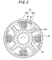
- FIG 2 is a cross-sectional view taken along the line II-II in FIG 1.
- the extruder system 80 includes an extruder 81 for axially extruding a rubber or plastic material G in a barrel 83 by rotation of an extrusion screw 82 arranged in the barrel, and a gear pump 91 driven by a rotational force for rotating the extrusion screw 82 so that a predetermined amount of the material G extruded from the extruder is discharged by engagement of gears.
- the gear pump 91 includes a casing 93 that is secured to the barrel 83, a ring gear 94 fixedly secured to the radially inner side of the casing 93, and a rotatable wall body 85 secured to the extrusion screw 82.
- the rotatable wall body 85 includes two side plates 85a, 85b extending perpendicularly to the rotational axis of the extrusion screw 82, and partition walls 85c for dividing the space between the side plates 85a, 85b in the circumferential direction, for example, into four chambers 87 as shown.
- Each chamber 87 is provided therein with a planetary pinion 86 that is rotatable about an axis in parallel with the rotational axis of the extrusion screw 82.
- Each planetary pinion 86 is arranged so as to divide the chamber 87 into a suction sub-chamber and a discharge sub-chamber, and meshed with the ring gear 94.
- the rotatable wall body 85 is rotated to cause an orbital revolution of the planetary pinions 86.
- the planetary pinions 86 undergo a planetary rotation in a direction opposite to the direction of the orbital revolution.
- the side plate 85a is situated on the suction side adjacent to the extrusion screw 82, and the side plate 85b is situated on the discharge side remote from the extrusion screw 82.
- the side plate 85a on the suction side is formed with suction ports 88a which are in communication with the respective suction sub-chambers 87a, while the side plate 85b on the discharge side is formed with discharge ports 88b which are in communication with the respective discharge sub-chambers 87b.
- the material G extruded by the rotation of the extrusion screw 82 is passed through the suction port 88a in the side plate 85a on the suction side, fed into the radially outer side of the suction sub-chamber 87a, and forced into the gap between the neighboring teeth of the planetary pinions 86.
- the material G is successively moved to the radially inner side of the suction sub-chamber 87a, the radially inner side of the discharge sub-chamber 87a, and the radially outer side of the discharge sub-chamber 87a.
- the volume of the material G that can be discharged by advancement of the planetary pinion 86 by one pitch is determined by the teeth profile of the planetary pinion 86, and it is possible to maintain a constant discharge volume of the material G by maintaining the rotational speed of the extrusion screw 82 constant.
- the known extruder system 80 described above is considered to be generally satisfactory in terms of its basic functions, though the following problems may be encountered.
- the extruder system 80 is limited in its application in view of a poor response characteristic, which is noticeable particularly when the operation of the extruder system 80 is started or stopped, or when the discharge volume of the material G is controlled in a real-time manner by continuously changing the rotational speed of the extrusion screw. This is due to a large inertia of the rotating elements as a whole, inclusive of the rotatable wall body 85 and the planetary pinions 86 which are rotated together with the extrusion screw 82.
- a second problem is that the known extruder system 80 as a whole is highly costly due to a particular arrangement wherein the planetary rotation force of the planetary pinions 86 for transferring the extruded material G is generated by the orbital revolution of the planetary pinions in engagement with the ring gear 94, given that the ring gear 94 has to be formed with precisely machined internal teeth and is thus very expensive.
- a third problem of the known extruder system 80 is that, in order to increase the discharge volume of the system by increasing the rotational speed of the planetary pinions 86, the ring gear 92 must have a large diameter. This not only results in increased dimension and cost of the gear pump section, but also necessitates that the engagement region of the gear teeth to be fed with the material G from the extrusion screw 82 be shifted to the radially outer side of the gear pump with an increased dimension. In order to smoothly guide the material G from the tip end of the extrusion screw 82 to the suction port 88a, from a practical viewpoint, it is necessary to increase the diameter of the extrusion screw 82 at its tip end, with the result that the production cost of the extrusion screw also increases.
- a fourth problem is that it is difficult to effectively cool the material G which generates heat within the gear pump 91 of the known extrusion system 80.
- it is necessary to suppress the discharge volume in order to prevent scorching of the material G.
- Heat generation of the material G occurs mainly as a result of its friction with the surrounding wall surface. In the case of the known extrusion system, such friction takes place in the radially inner region of the chamber 87.
- it would be necessary to supply coolant through a cooling jacket which extends through the wall body 85.
- the cooling jacket would be very complicated in structure.
- the present invention has been achieved in view of these problems of the prior art. It is therefore an object of the present invention to provide an extruder system comprising a gear pump, which is excellent in response characteristics in operation, which can be realized at low cost, and which is capable of cooling the material.
- a first aspect of the present invention resides in an extruder system with a gear pump, comprising an extruder for axially extruding a rubber or plastic material in a barrel by rotation of an extrusion screw arranged in the barrel, and a gear pump driven by a rotational force for rotating the extrusion screw so that a predetermined amount of the material extruded from the extruder is discharged by engagement of gears.
- the gear pump comprises a driving pinion arranged coaxially to the extrusion screw and fixedly secured to a tip end of the extrusion screw, at least one driven pinion meshed with, and driven by the driving pinion and rotatable about a rotational shaft that is parallel to a rotational shaft of the extrusion screw, and a gear casing accommodating these pinions therein.
- the gear casing comprises side plates arranged on both axial sides of the pinions leaving a small clearance therefrom, and extending perpendicularly to the rotational shaft of the extrusion screw, and a casing body arranged between the side plates and enclosing a space on a radially outer side of the pinions.
- the rotational shaft of the driven pinion is fixedly secured to the side plates.
- the side plates include a side plate situated on the suction side adjacent to the extrusion screw and a side plate situated on the discharge side remote from the extrusion screw.
- the side plate on the suction side has a suction port that is arranged opposite to that side of engagement region between the driving pinion and the driven pinion, where their teeth are being disengaged from each other.
- the side plate on the discharge side has a discharge port that is arranged opposite to that side of the engagement region between the driving pinion and the driven pinion, where their teeth are being engaged from each other.
- the suction port and the discharge port are maintained out of an axial communication with each other by said pinions.
- a second aspect of the present resides in an extruder system according to the first aspect, wherein the teeth of the driving pinion and the driven pinion are comprised of bevel gear teeth.
- a third aspect of the present invention resides in an extruder system according to the first or second aspect, wherein the side plate on the suction side and the side plate on the discharge side are formed with recesses for preventing jamming of the material, are these recesses are situated at locations on those side of the suction port and the discharge port, which are adjacent to the engagement region of the driving pinion and the driven pinion, respectively.
- a fourth aspect of the present invention resides in an extruder system according to any one of the first to the third aspects, wherein the casing includes a cooling jacket.
- the material extruded axially from the tip end of the extrusion screw is forced into the gap between the neighboring teeth of the driven pinion, at a location adjacent to the engagement region between the driving pinion and the driven pinion, and is subsequently once moved away from the center axis of the driving pinion and then toward the center axis of the driving pinion so as to be discharged at a location adjacent to the engagement region between the driving pinion and the driven pinion. Therefore, the following advantages are achieved.
- the teeth of the driving pinion and the driven pinion are comprised of bevel gear teeth, it is possible, during the rotation of these pinions, to generate a force having a component effective to advance the material axially toward the tip end side, thereby allowing efficient suction and discharge of the material.
- the side plates are formed with recesses for preventing jamming of the material, it is possible to avoid a situation wherein the material leaks into the engagement region thereby causing forced deformation of the pinions, and also to avoid leakage of the material from the suction side to the discharge side, thereby improving a material metering accuracy.
- the casing is provided with a cooling jacket, it is possible to prevent abnormal elevation in temperature of the material, and suppress scorching of the material and deterioration in terms of the material quality.
- FIG. 1 is a fragmentary longitudinal-sectional view showing the known extruder system in a plane including the rotational axis of the extrusion screw;
- FIG. 3 is a fragmentary longitudinal-sectional view showing the extruder system according to the embodiment of the present invention, the section being taken in a plane including the rotational axis of the extrusion screw;
- FIG 4 is a cross-sectional view taken along the line A-A in FIG 3;
- FIG 5 is a perspective view showing the engagement of driving and driven pinions;
- FIG 6 is a perspective view of the side plate;
- FIG 7 is a perspective view of the casing;
- FIGS. 8(a) and 8(b) are perspective views showing the locations of the openings and the recesses as being associated with the pinions.
- the following description refers to the material to be extruded as being a rubber, though the description applies equally to plastic materials as well.
- the extruder system with integrated gear pump according to the invention which is designated as a whole by reference numeral 1, includes an extruder 2 that comprises an extrusion screw 21 and a barrel 22 accommodating the extrusion screw 21 so that a rubber G within the barrel 22 is extruded in the axial direction under the rotation of the extrusion screw 21, as well as a gear pump 3 that is driven by a rotational force for rotating the extrusion screw 21 so as to discharge a constant volume of the extruded rubber G by engagement of the gear teeth.
- the gear pump 3 includes a driving pinion 4 which is arranged coaxially to the extrusion screw 21 and fixedly secured to a tip end of the extrusion screw 21, at least one driven pinion 5 engaged with, and driven by the driving pinion 4 so as to rotate about a shaft that is parallel to the rotational axis L of the driving pinion 4, and a gear casing 11 fixedly secured to the barrel 22 to accommodate these pinions therein.
- a driving pinion 4 which is arranged coaxially to the extrusion screw 21 and fixedly secured to a tip end of the extrusion screw 21, at least one driven pinion 5 engaged with, and driven by the driving pinion 4 so as to rotate about a shaft that is parallel to the rotational axis L of the driving pinion 4, and a gear casing 11 fixedly secured to the barrel 22 to accommodate these pinions therein.
- the gear casing 11 includes side plates 12, 13 arranged on both axial sides of the pinions 4, 5 leaving a small clearance therefrom, and extending perpendicularly to the rotational axis L of the extrusion screw, and a casing body 14 arranged between the side plates 12, 13 and enclosing a space on a radially outer side of the pinions 4, 5.
- the driven pinion 4 has a rotary shaft 15 which is fixedly secured to the side plates 12, 13.
- the side plate 12 situated on the suction side adjacent to the extrusion screw 21 has a suction port 12a that is arranged opposite to that side of engagement region between the driving pinion 4 and the driven pinion 5, where their teeth are being disengaged from each other.
- the side plate 13 situated on the discharge side remote from the extrusion screw 21 has a discharge port 13a that is arranged opposite to that side of the engagement region between the driving pinion 4 and the driven pinion 5, where their teeth are being engaged from each other.
- the suction port 12a and the discharge port 13a are maintained out of an axial communication with each other by the pinions 4, 5.
- a discharge head 24 having a mouthpiece orifice 25 is secured to the side plate 13 on the discharge side, on its side that is remote from the extrusion screw 21.
- the discharge head 24 cooperates with the side plate 13 to define a straightening chamber 26 for the rubber G
- the rubber G extruded axially from the tip end of the extrusion screw 21 under the rotation thereof is guided into the gear casing 11 through the suction port 12a in the side plate 12, and forced into the gap between the neighboring teeth of the driven pinion 5.
- the rubber G is once moved away from the driving pinion 4 to pass the radially outermost region in the gear casing 11, and then moved back toward the driving pinion 5.
- the gap of the driven pinion 5 filled with the rubber G reaches an engagement region between the driven pinion 5 and the driving pinion 4, the rubber G is removed out of the gap due to the progressive engagement of the pinions 4, 5.
- the removed rubber G is discharged out of the gear casing 11 through the discharge port 13a, supplied into the straightening chamber 26, and then extruded from the mouthpiece orifice 25 with a constant cross-sectional shape.
- FIG. 8(a) is a perspective view showing the locations of the suction ports 12a and the recesses for preventing jamming of the rubber G, as being associated with the pinions, wherein reference numeral 12a1 denotes the portions corresponding to the suction ports 12a, and 12b1 denotes the portions corresponding to the recesses for preventing jamming of the rubber G Similarly, FIG 8(b) is a perspective view showing the locations of the discharge ports 13a and the recesses for preventing jamming of the rubber G, as being associated with the pinions, wherein reference numeral 13a1 denotes the portions corresponding to the discharge ports 13a, and 13b1 denotes the portions corresponding to the recesses for preventing jamming of the rubber G.
- the extruder system 1 having a construction as described above, is capable of achieving the following advantages.
- Third, since the suction port 12a is situated immediately on the outer side of the driving pinion 4, it is unnecessary to enlarge the diameter of the extrusion screw 21 at its tip end.
- the teeth of the driving pinion 4 and the driven pinion 5 are comprised of bevel gear teeth, in order to efficiently achieve the suction and discharge of the rubber G
Landscapes
- Engineering & Computer Science (AREA)
- Mechanical Engineering (AREA)
- General Engineering & Computer Science (AREA)
- Extrusion Moulding Of Plastics Or The Like (AREA)
- Rotary Pumps (AREA)
- Details And Applications Of Rotary Liquid Pumps (AREA)
Abstract
Description
- The present invention relates to an extruder system with an integrated gear pump, applicable for measuring and extruding a predetermined amount of rubber or plastic material, and contemplates to provide a compact arrangement of such an extruder.
- In order to extrude a constant amount of rubber or plastic material, it has been a conventional practice to use a combined system wherein a gear pump is arranged on a downstream side of an extruder, and to drive the gear pump independently from the extruder. However, such a combined system requires considerable space for installation. Thus, there has been proposed an extruder system provided with a gear pump, wherein the drive shaft for the extrusion screw is simultaneously used to drive the gear pump. Attention is drawn, e.g., to the pamphlet of International Publication
WO 2003/011561 . - FIG. 1 is a fragmentary longitudinal-sectional view showing the known extruder system in a plane including the rotational axis of the extrusion screw, and FIG 2 is a cross-sectional view taken along the line II-II in FIG 1. The
extruder system 80 includes anextruder 81 for axially extruding a rubber or plastic material G in abarrel 83 by rotation of anextrusion screw 82 arranged in the barrel, and agear pump 91 driven by a rotational force for rotating theextrusion screw 82 so that a predetermined amount of the material G extruded from the extruder is discharged by engagement of gears. Thegear pump 91 includes acasing 93 that is secured to thebarrel 83, aring gear 94 fixedly secured to the radially inner side of thecasing 93, and arotatable wall body 85 secured to theextrusion screw 82. - The
rotatable wall body 85 includes twoside plates extrusion screw 82, andpartition walls 85c for dividing the space between theside plates chambers 87 as shown. Eachchamber 87 is provided therein with aplanetary pinion 86 that is rotatable about an axis in parallel with the rotational axis of theextrusion screw 82. Eachplanetary pinion 86 is arranged so as to divide thechamber 87 into a suction sub-chamber and a discharge sub-chamber, and meshed with thering gear 94. Thus, when theextrusion screw 82 is rotated, therotatable wall body 85 is rotated to cause an orbital revolution of theplanetary pinions 86. On this occasion, being meshed with thering gear 94, theplanetary pinions 86 undergo a planetary rotation in a direction opposite to the direction of the orbital revolution. - Among the two
side plates side plate 85a is situated on the suction side adjacent to theextrusion screw 82, and theside plate 85b is situated on the discharge side remote from theextrusion screw 82. Theside plate 85a on the suction side is formed with suction ports 88a which are in communication with therespective suction sub-chambers 87a, while theside plate 85b on the discharge side is formed withdischarge ports 88b which are in communication with therespective discharge sub-chambers 87b. - In operation of the known
extruder system 80 described above, the material G extruded by the rotation of theextrusion screw 82 is passed through the suction port 88a in theside plate 85a on the suction side, fed into the radially outer side of thesuction sub-chamber 87a, and forced into the gap between the neighboring teeth of theplanetary pinions 86. As theplanetary pinion 86 undergoes planetary rotation, while being retained in the gap between the neighboring teeth of theplanetary pinion 86, the material G is successively moved to the radially inner side of thesuction sub-chamber 87a, the radially inner side of thedischarge sub-chamber 87a, and the radially outer side of thedischarge sub-chamber 87a. When the material G reaches the radially outermost position in thedischarge sub-chamber 87b, where theplanetary pinion 86 comes into engagement with thering gear 94, the material G is discharged through thedischarge port 88b toward the axial tip end of the extruder system, due to the engagement between theplanetary pinion 86 and theplanetary pinion 86. On the other hand, the gap of theplanetary pinion 86, from which the material has been discharged, is moved to thesuction sub-chamber 87a so as to be filled with a new batch of the extruded material G. - In this way, the volume of the material G that can be discharged by advancement of the
planetary pinion 86 by one pitch is determined by the teeth profile of theplanetary pinion 86, and it is possible to maintain a constant discharge volume of the material G by maintaining the rotational speed of theextrusion screw 82 constant. - The known
extruder system 80 described above is considered to be generally satisfactory in terms of its basic functions, though the following problems may be encountered. First of all, theextruder system 80 is limited in its application in view of a poor response characteristic, which is noticeable particularly when the operation of theextruder system 80 is started or stopped, or when the discharge volume of the material G is controlled in a real-time manner by continuously changing the rotational speed of the extrusion screw. This is due to a large inertia of the rotating elements as a whole, inclusive of therotatable wall body 85 and theplanetary pinions 86 which are rotated together with theextrusion screw 82. - A second problem is that the known
extruder system 80 as a whole is highly costly due to a particular arrangement wherein the planetary rotation force of theplanetary pinions 86 for transferring the extruded material G is generated by the orbital revolution of the planetary pinions in engagement with thering gear 94, given that thering gear 94 has to be formed with precisely machined internal teeth and is thus very expensive. - A third problem of the known
extruder system 80 is that, in order to increase the discharge volume of the system by increasing the rotational speed of theplanetary pinions 86, the ring gear 92 must have a large diameter. This not only results in increased dimension and cost of the gear pump section, but also necessitates that the engagement region of the gear teeth to be fed with the material G from theextrusion screw 82 be shifted to the radially outer side of the gear pump with an increased dimension. In order to smoothly guide the material G from the tip end of theextrusion screw 82 to the suction port 88a, from a practical viewpoint, it is necessary to increase the diameter of theextrusion screw 82 at its tip end, with the result that the production cost of the extrusion screw also increases. - A fourth problem is that it is difficult to effectively cool the material G which generates heat within the
gear pump 91 of theknown extrusion system 80. In the absence of effective cooling of the material G, it is necessary to suppress the discharge volume in order to prevent scorching of the material G. Heat generation of the material G occurs mainly as a result of its friction with the surrounding wall surface. In the case of the known extrusion system, such friction takes place in the radially inner region of thechamber 87. Thus, in order to achieve an effective cooling, it would be necessary to supply coolant through a cooling jacket which extends through thewall body 85. However, since thewall body 85 itself undergoes rotation during the operation of the extrusion system, the cooling jacket would be very complicated in structure. - The present invention has been achieved in view of these problems of the prior art. It is therefore an object of the present invention to provide an extruder system comprising a gear pump, which is excellent in response characteristics in operation, which can be realized at low cost, and which is capable of cooling the material.
- (1) A first aspect of the present invention resides in an extruder system with a gear pump, comprising an extruder for axially extruding a rubber or plastic material in a barrel by rotation of an extrusion screw arranged in the barrel, and a gear pump driven by a rotational force for rotating the extrusion screw so that a predetermined amount of the material extruded from the extruder is discharged by engagement of gears. The gear pump comprises a driving pinion arranged coaxially to the extrusion screw and fixedly secured to a tip end of the extrusion screw, at least one driven pinion meshed with, and driven by the driving pinion and rotatable about a rotational shaft that is parallel to a rotational shaft of the extrusion screw, and a gear casing accommodating these pinions therein. The gear casing comprises side plates arranged on both axial sides of the pinions leaving a small clearance therefrom, and extending perpendicularly to the rotational shaft of the extrusion screw, and a casing body arranged between the side plates and enclosing a space on a radially outer side of the pinions. The rotational shaft of the driven pinion is fixedly secured to the side plates. The side plates include a side plate situated on the suction side adjacent to the extrusion screw and a side plate situated on the discharge side remote from the extrusion screw. The side plate on the suction side has a suction port that is arranged opposite to that side of engagement region between the driving pinion and the driven pinion, where their teeth are being disengaged from each other. The side plate on the discharge side has a discharge port that is arranged opposite to that side of the engagement region between the driving pinion and the driven pinion, where their teeth are being engaged from each other. The suction port and the discharge port are maintained out of an axial communication with each other by said pinions.
- (2) A second aspect of the present resides in an extruder system according to the first aspect, wherein the teeth of the driving pinion and the driven pinion are comprised of bevel gear teeth.
- (3) A third aspect of the present invention resides in an extruder system according to the first or second aspect, wherein the side plate on the suction side and the side plate on the discharge side are formed with recesses for preventing jamming of the material, are these recesses are situated at locations on those side of the suction port and the discharge port, which are adjacent to the engagement region of the driving pinion and the driven pinion, respectively.
- (4) A fourth aspect of the present invention resides in an extruder system according to any one of the first to the third aspects, wherein the casing includes a cooling jacket.
- With the features of the present invention in its first aspect, the material extruded axially from the tip end of the extrusion screw is forced into the gap between the neighboring teeth of the driven pinion, at a location adjacent to the engagement region between the driving pinion and the driven pinion, and is subsequently once moved away from the center axis of the driving pinion and then toward the center axis of the driving pinion so as to be discharged at a location adjacent to the engagement region between the driving pinion and the driven pinion. Therefore, the following advantages are achieved.
- First, since it is only the driving pinion, which is secured to, and rotatable with the extrusion screw, the rotating elements in the extruder system has a low inertia to ensure an excellent response characteristic.
- Second, since a ring gear with internal teeth is not required, it is possible to reduce the cost.
- Third, since the material suction port is situated adjacent to the engagement region between the driving pinion and the driven pinion, and at least closer to the driving pinion than the center axis of the driven pinion, it is unnecessary to enlarge the diameter of the extrusion screw at its tip end, and possible to further reduce the cost.
- Fourth, even though friction causing heat generation occurs between the material and the casing, the stationary casing is provided with a cooling jacket to effectively cool the material and prevent scorching of the material.
- With the features of the present invention in its second aspect, since the teeth of the driving pinion and the driven pinion are comprised of bevel gear teeth, it is possible, during the rotation of these pinions, to generate a force having a component effective to advance the material axially toward the tip end side, thereby allowing efficient suction and discharge of the material.
- With the features of the present invention in its third aspect, since the side plates are formed with recesses for preventing jamming of the material, it is possible to avoid a situation wherein the material leaks into the engagement region thereby causing forced deformation of the pinions, and also to avoid leakage of the material from the suction side to the discharge side, thereby improving a material metering accuracy.
- With the features of the present invention in its fourth aspect, since the casing is provided with a cooling jacket, it is possible to prevent abnormal elevation in temperature of the material, and suppress scorching of the material and deterioration in terms of the material quality.
- FIG. 1 is a fragmentary longitudinal-sectional view showing the known extruder system in a plane including the rotational axis of the extrusion screw;
- FIG 2 is a cross-sectional view taken along the line II-II in FIG 1;
- FIG 3 is a fragmentary longitudinal-sectional view showing the extruder system according to an embodiment of the present invention, the section being taken in a plane including the rotational axis of the extrusion screw;
- FIG 4 is a cross-sectional view taken along the line A-A in FIG 3;
- FIG 5 is a perspective view showing the engagement of driving and driven pinions;
- FIG 6 is a perspective view of the side plate;
- FIG 7 is a perspective view of the casing; and
- FIGS. 8(a) and 8(b) are perspective views showing the locations of the openings and the recesses as being associated with the pinions.
- A preferred embodiment of the present invention will be described below with reference to the drawings, wherein FIG. 3 is a fragmentary longitudinal-sectional view showing the extruder system according to the embodiment of the present invention, the section being taken in a plane including the rotational axis of the extrusion screw; FIG 4 is a cross-sectional view taken along the line A-A in FIG 3; FIG 5 is a perspective view showing the engagement of driving and driven pinions; FIG 6 is a perspective view of the side plate; FIG 7 is a perspective view of the casing; and FIGS. 8(a) and 8(b) are perspective views showing the locations of the openings and the recesses as being associated with the pinions. The following description refers to the material to be extruded as being a rubber, though the description applies equally to plastic materials as well.
- The extruder system with integrated gear pump according to the invention, which is designated as a whole by reference numeral 1, includes an
extruder 2 that comprises anextrusion screw 21 and abarrel 22 accommodating theextrusion screw 21 so that a rubber G within thebarrel 22 is extruded in the axial direction under the rotation of theextrusion screw 21, as well as a gear pump 3 that is driven by a rotational force for rotating theextrusion screw 21 so as to discharge a constant volume of the extruded rubber G by engagement of the gear teeth. - The gear pump 3 includes a
driving pinion 4 which is arranged coaxially to theextrusion screw 21 and fixedly secured to a tip end of theextrusion screw 21, at least one drivenpinion 5 engaged with, and driven by the drivingpinion 4 so as to rotate about a shaft that is parallel to the rotational axis L of the drivingpinion 4, and agear casing 11 fixedly secured to thebarrel 22 to accommodate these pinions therein. - The
gear casing 11 includesside plates pinions casing body 14 arranged between theside plates pinions pinion 4 has arotary shaft 15 which is fixedly secured to theside plates side plates side plate 12 situated on the suction side adjacent to theextrusion screw 21 has asuction port 12a that is arranged opposite to that side of engagement region between the drivingpinion 4 and the drivenpinion 5, where their teeth are being disengaged from each other. Theside plate 13 situated on the discharge side remote from theextrusion screw 21 has adischarge port 13a that is arranged opposite to that side of the engagement region between the drivingpinion 4 and the drivenpinion 5, where their teeth are being engaged from each other. Thesuction port 12a and thedischarge port 13a are maintained out of an axial communication with each other by thepinions - Furthermore, a
discharge head 24 having amouthpiece orifice 25 is secured to theside plate 13 on the discharge side, on its side that is remote from theextrusion screw 21. Thedischarge head 24 cooperates with theside plate 13 to define a straighteningchamber 26 for the rubber G - In the extruder system 1 having a construction as described above, the rubber G extruded axially from the tip end of the
extrusion screw 21 under the rotation thereof is guided into thegear casing 11 through thesuction port 12a in theside plate 12, and forced into the gap between the neighboring teeth of the drivenpinion 5. As the driven pinion undergoes a planetary rotation, the rubber G is once moved away from the drivingpinion 4 to pass the radially outermost region in thegear casing 11, and then moved back toward the drivingpinion 5. When the gap of the drivenpinion 5 filled with the rubber G reaches an engagement region between the drivenpinion 5 and thedriving pinion 4, the rubber G is removed out of the gap due to the progressive engagement of thepinions gear casing 11 through thedischarge port 13a, supplied into the straighteningchamber 26, and then extruded from themouthpiece orifice 25 with a constant cross-sectional shape. - As shown in FIG 7, the
casing body 14 is provided withrecesses 14a at locations adjacent to thesuction ports 12a and thedischarge ports 13a in theside plates suction ports 12a and the recesses for preventing jamming of the rubber G, as being associated with the pinions, wherein reference numeral 12a1 denotes the portions corresponding to thesuction ports 12a, and 12b1 denotes the portions corresponding to the recesses for preventing jamming of the rubber G Similarly, FIG 8(b) is a perspective view showing the locations of thedischarge ports 13a and the recesses for preventing jamming of the rubber G, as being associated with the pinions, wherein reference numeral 13a1 denotes the portions corresponding to thedischarge ports 13a, and 13b1 denotes the portions corresponding to the recesses for preventing jamming of the rubber G. - The extruder system 1 having a construction as described above, is capable of achieving the following advantages. First, in the
gear pump 11, since it is only the drivingpinion 4, which is secured to, and rotatable with theextrusion screw 21, the rotating elements in the extruder system has a low inertia to ensure an excellent response characteristic. Second, since the drivenpinions 5 for transferring the rubber G from the suction side to the discharge side is directly engaged with, and driven by the drivingpinion 4, an expensive ring gear is not required. Third, since thesuction port 12a is situated immediately on the outer side of the drivingpinion 4, it is unnecessary to enlarge the diameter of theextrusion screw 21 at its tip end. Fourth, in connection with thecasing body 14 fixedly secured to thebarrel 22, which undergoes a friction with the rubber G, when it is desired to suppress heat generation of the rubber G, a coolingjacket 16 may be readily provided, as shown in FIG 7. - Preferably, the teeth of the driving
pinion 4 and the drivenpinion 5 are comprised of bevel gear teeth, in order to efficiently achieve the suction and discharge of the rubber G
Claims (4)
- An extruder system with a gear pump, comprising an extruder for axially extruding a rubber or plastic material in a barrel by rotation of an extrusion screw arranged in the barrel, and a gear pump driven by a rotational force for rotating the extrusion screw so that a predetermined amount of the material extruded from the extruder is discharged by engagement of gears, wherein:said gear pump comprises a driving pinion arranged coaxially to the extrusion screw and fixedly secured to a tip end of the extrusion screw, at least one driven pinion meshed with, and driven by the driving pinion and rotatable about a rotational shaft that is parallel to a rotational shaft of the extrusion screw, and a gear casing accommodating these pinions therein;said gear casing comprises side plates arranged on both axial sides of the pinions leaving a small clearance therefrom, and extending perpendicularly to the rotational shaft of the extrusion screw, and a casing body arranged between the side plates and enclosing a space on a radially outer side of the pinions;said rotational shaft of the driven pinion is fixedly secured to the side plates; andsaid side plates includes a side plate situated on the suction side adjacent to the extrusion screw and a side plate situated on the discharge side remote from the extrusion screw, said side plate on the suction side having a suction port that is arranged opposite to that side of engagement region between the driving pinion and the driven pinion, where their teeth are being disengaged from each other, and said side plate on the discharge side having a discharge port that is arranged opposite to that side of the engagement region between the driving pinion and the driven pinion, where their teeth are being engaged from each other, said suction port and said discharge port being maintained out of an axial communication with each other by said pinions.
- The extruder system according to claim 1, wherein the teeth of said driving pinion and said driven pinion are comprised of bevel gear teeth.
- The extruder system according to claim 1 or 2, wherein said side plates on the suction and discharge sides are formed with recesses for preventing jamming of the material, respectively, said recesses being situated at locations on those side of the suction port and the discharge port, which are adjacent to the engagement region of the driving pinion and the driven pinion, respectively.
- The extruder system according to any one of claims 1 to 3, wherein said casing includes a cooling jacket.
Applications Claiming Priority (2)
| Application Number | Priority Date | Filing Date | Title |
|---|---|---|---|
| JP2004010882A JP4462938B2 (en) | 2004-01-19 | 2004-01-19 | Extruder with gear pump |
| PCT/JP2004/019385 WO2005068837A1 (en) | 2004-01-19 | 2004-12-24 | Extruder with gear pump |
Publications (3)
| Publication Number | Publication Date |
|---|---|
| EP1731764A1 true EP1731764A1 (en) | 2006-12-13 |
| EP1731764A4 EP1731764A4 (en) | 2012-01-04 |
| EP1731764B1 EP1731764B1 (en) | 2016-11-16 |
Family
ID=34792314
Family Applications (1)
| Application Number | Title | Priority Date | Filing Date |
|---|---|---|---|
| EP04807741.6A Expired - Lifetime EP1731764B1 (en) | 2004-01-19 | 2004-12-24 | Extruder with gear pump |
Country Status (4)
| Country | Link |
|---|---|
| US (1) | US7942567B2 (en) |
| EP (1) | EP1731764B1 (en) |
| JP (1) | JP4462938B2 (en) |
| WO (1) | WO2005068837A1 (en) |
Cited By (1)
| Publication number | Priority date | Publication date | Assignee | Title |
|---|---|---|---|---|
| US7607818B2 (en) * | 2007-02-16 | 2009-10-27 | Vmi-Az Extrusion Gmbh | Extruder with gear pump |
Families Citing this family (8)
| Publication number | Priority date | Publication date | Assignee | Title |
|---|---|---|---|---|
| DE102005048847A1 (en) * | 2005-10-12 | 2007-04-19 | Vmi-Az Extrusion Gmbh | conveyor |
| US8007163B2 (en) * | 2009-05-28 | 2011-08-30 | Chernoff Larry J | Mechanical fluid mixer system |
| JP5395631B2 (en) * | 2009-11-13 | 2014-01-22 | 上田鉄工株式会社 | Gear pump |
| EP3112133B1 (en) * | 2014-02-25 | 2020-07-01 | Yuyama, Seiichi | 3d printer |
| DE102017111275B4 (en) * | 2017-05-23 | 2020-02-13 | Gneuss Gmbh | Extruder screw for a multi-screw extruder for plastic extrusion and multi-screw extruder |
| MY210493A (en) * | 2019-03-20 | 2025-09-25 | Mitsubishi Chem Corp | Twin-screw extruder |
| CN109940848A (en) * | 2019-04-11 | 2019-06-28 | 德清县宏兴轻工机械厂 | A kind of flow of material control device of reciprocating push plate machine inlet |
| CN115056453B (en) * | 2022-07-06 | 2023-12-15 | 宁波迈巴赫工程塑料有限公司 | Plastic plate extrusion device for insulating end plate of hydrogen fuel cell stack |
Family Cites Families (13)
| Publication number | Priority date | Publication date | Assignee | Title |
|---|---|---|---|---|
| US1595470A (en) * | 1924-05-12 | 1926-08-10 | Edgar H Johnson | Extruding machine |
| US2785438A (en) * | 1954-08-18 | 1957-03-19 | Frank W Egan & Company | Plastics extruder with mixing head |
| US4336213A (en) * | 1980-02-06 | 1982-06-22 | Fox Steve A | Plastic extrusion apparatus and method |
| US5156781A (en) * | 1990-12-24 | 1992-10-20 | Bridgestone Corporation | Compact precision extrusion method |
| US5267847A (en) * | 1990-12-24 | 1993-12-07 | Bridgestone Corporation | Compact precision extrusion system |
| JP2000034985A (en) * | 1998-07-16 | 2000-02-02 | Shimadzu Corp | Gear pump |
| US6468067B1 (en) * | 1999-09-16 | 2002-10-22 | Toyo Tire & Rubber Co., Ltd. | Composite extruding apparatus of rubber and method of extruding unvulcanized rubber |
| JP2001241386A (en) * | 2000-02-28 | 2001-09-07 | Naoteru Maeda | In-tank installation type screw pump |
| GB0009307D0 (en) * | 2000-04-15 | 2000-05-31 | Az Formen & Masch Gmbh | Cold feed gear pump extruders |
| EP1390190B1 (en) * | 2001-05-30 | 2005-03-02 | Röhm GmbH & Co. KG | Method and device for regulating pressure in a single-screw degassing extruder or in a cascade extruder |
| DE10136851A1 (en) * | 2001-07-24 | 2003-02-13 | Berstorff Gmbh | Extruder gear pump combination for use as an injection unit in injection molding machines |
| DE10154860A1 (en) * | 2001-11-08 | 2003-05-22 | Az Formen & Maschbau Gmbh | extruder arrangement |
| DE10348985B3 (en) * | 2003-10-22 | 2005-05-19 | Berstorff Gmbh | gear pump |
-
2004
- 2004-01-19 JP JP2004010882A patent/JP4462938B2/en not_active Expired - Fee Related
- 2004-12-24 US US10/586,475 patent/US7942567B2/en not_active Expired - Fee Related
- 2004-12-24 WO PCT/JP2004/019385 patent/WO2005068837A1/en not_active Ceased
- 2004-12-24 EP EP04807741.6A patent/EP1731764B1/en not_active Expired - Lifetime
Cited By (3)
| Publication number | Priority date | Publication date | Assignee | Title |
|---|---|---|---|---|
| US7607818B2 (en) * | 2007-02-16 | 2009-10-27 | Vmi-Az Extrusion Gmbh | Extruder with gear pump |
| EP1958757A3 (en) * | 2007-02-16 | 2011-08-03 | VMI - AZ Extrusion GmbH | Extruder |
| KR101276937B1 (en) | 2007-02-16 | 2013-06-19 | 파우엠이-아체트 엑스트루지온 게엠베하 | Extruder |
Also Published As
| Publication number | Publication date |
|---|---|
| JP2005201215A (en) | 2005-07-28 |
| US7942567B2 (en) | 2011-05-17 |
| JP4462938B2 (en) | 2010-05-12 |
| US20070264144A1 (en) | 2007-11-15 |
| WO2005068837A1 (en) | 2005-07-28 |
| EP1731764A4 (en) | 2012-01-04 |
| EP1731764B1 (en) | 2016-11-16 |
Similar Documents
| Publication | Publication Date | Title |
|---|---|---|
| EP1731764B1 (en) | Extruder with gear pump | |
| US4457677A (en) | High torque, low speed hydraulic motor | |
| TW201741575A (en) | Speed-switchable reduction gear | |
| JP5060014B2 (en) | Screw extruder and gear pump for high viscosity media | |
| US5620315A (en) | Gear pump for feeding of fluids | |
| DE2601880C2 (en) | Hydraulic internal gear pump | |
| CA2500411C (en) | Extruder/gear pump assembly | |
| US20110128812A1 (en) | Multiple-screw extruder | |
| US20190284974A1 (en) | Oil supply structure of transmission | |
| DE102011054607A1 (en) | vacuum pump | |
| RU2294436C1 (en) | Internal engagement rotary machine | |
| US20200271210A1 (en) | Planet gear support shaft, method for manufacturing planet gear support shaft, and planetary gear unit | |
| EP2634430B1 (en) | Gear pump assembly | |
| JP2009006607A (en) | Extruder with gear pump | |
| US12234823B2 (en) | Internal gear pump and internal gear motor | |
| JP2006103199A (en) | Gear pump extruder | |
| JP2017112671A (en) | Electric motor | |
| JP2009052481A (en) | Fluid discharge device and extruder | |
| EP1897673B1 (en) | Method for extruding strip rubber for tire structuring member | |
| US20070234836A1 (en) | Drive union for a twin-screw machine | |
| JPH04255584A (en) | Internal gear pump for hydraulic fluid | |
| CN101293397A (en) | Complex screw multifunctional extruding machine | |
| US20210170661A1 (en) | System and method for extruding complex profiles from elastomer mixtures | |
| JP2004538182A (en) | Positive displacement pump | |
| JP7851492B2 (en) | extruder |
Legal Events
| Date | Code | Title | Description |
|---|---|---|---|
| PUAI | Public reference made under article 153(3) epc to a published international application that has entered the european phase |
Free format text: ORIGINAL CODE: 0009012 |
|
| 17P | Request for examination filed |
Effective date: 20060718 |
|
| AK | Designated contracting states |
Kind code of ref document: A1 Designated state(s): DE FR IT |
|
| DAX | Request for extension of the european patent (deleted) | ||
| RBV | Designated contracting states (corrected) |
Designated state(s): DE FR IT |
|
| A4 | Supplementary search report drawn up and despatched |
Effective date: 20111205 |
|
| RIC1 | Information provided on ipc code assigned before grant |
Ipc: B29C 47/12 20060101ALI20111129BHEP Ipc: F04C 2/18 20060101AFI20111129BHEP |
|
| 17Q | First examination report despatched |
Effective date: 20120420 |
|
| GRAP | Despatch of communication of intention to grant a patent |
Free format text: ORIGINAL CODE: EPIDOSNIGR1 |
|
| INTG | Intention to grant announced |
Effective date: 20160530 |
|
| GRAS | Grant fee paid |
Free format text: ORIGINAL CODE: EPIDOSNIGR3 |
|
| GRAA | (expected) grant |
Free format text: ORIGINAL CODE: 0009210 |
|
| AK | Designated contracting states |
Kind code of ref document: B1 Designated state(s): DE FR IT |
|
| REG | Reference to a national code |
Ref country code: FR Ref legal event code: PLFP Year of fee payment: 13 |
|
| REG | Reference to a national code |
Ref country code: DE Ref legal event code: R096 Ref document number: 602004050323 Country of ref document: DE |
|
| REG | Reference to a national code |
Ref country code: DE Ref legal event code: R096 Ref document number: 602004050323 Country of ref document: DE |
|
| PGFP | Annual fee paid to national office [announced via postgrant information from national office to epo] |
Ref country code: DE Payment date: 20161213 Year of fee payment: 13 |
|
| PGFP | Annual fee paid to national office [announced via postgrant information from national office to epo] |
Ref country code: FR Payment date: 20161222 Year of fee payment: 13 |
|
| PGFP | Annual fee paid to national office [announced via postgrant information from national office to epo] |
Ref country code: IT Payment date: 20170227 Year of fee payment: 13 |
|
| REG | Reference to a national code |
Ref country code: DE Ref legal event code: R097 Ref document number: 602004050323 Country of ref document: DE |
|
| PLBE | No opposition filed within time limit |
Free format text: ORIGINAL CODE: 0009261 |
|
| STAA | Information on the status of an ep patent application or granted ep patent |
Free format text: STATUS: NO OPPOSITION FILED WITHIN TIME LIMIT |
|
| 26N | No opposition filed |
Effective date: 20170817 |
|
| REG | Reference to a national code |
Ref country code: DE Ref legal event code: R119 Ref document number: 602004050323 Country of ref document: DE |
|
| REG | Reference to a national code |
Ref country code: FR Ref legal event code: ST Effective date: 20180831 |
|
| PG25 | Lapsed in a contracting state [announced via postgrant information from national office to epo] |
Ref country code: IT Free format text: LAPSE BECAUSE OF NON-PAYMENT OF DUE FEES Effective date: 20171224 Ref country code: DE Free format text: LAPSE BECAUSE OF NON-PAYMENT OF DUE FEES Effective date: 20180703 Ref country code: FR Free format text: LAPSE BECAUSE OF NON-PAYMENT OF DUE FEES Effective date: 20180102 |