EP1731671A1 - Arrangement and method for starting a machine - Google Patents
Arrangement and method for starting a machine Download PDFInfo
- Publication number
- EP1731671A1 EP1731671A1 EP06011171A EP06011171A EP1731671A1 EP 1731671 A1 EP1731671 A1 EP 1731671A1 EP 06011171 A EP06011171 A EP 06011171A EP 06011171 A EP06011171 A EP 06011171A EP 1731671 A1 EP1731671 A1 EP 1731671A1
- Authority
- EP
- European Patent Office
- Prior art keywords
- alarm
- machine
- sound
- sound sources
- arrangement according
- Prior art date
- Legal status (The legal status is an assumption and is not a legal conclusion. Google has not performed a legal analysis and makes no representation as to the accuracy of the status listed.)
- Granted
Links
Images


Classifications
-
- D—TEXTILES; PAPER
- D21—PAPER-MAKING; PRODUCTION OF CELLULOSE
- D21G—CALENDERS; ACCESSORIES FOR PAPER-MAKING MACHINES
- D21G9/00—Other accessories for paper-making machines
- D21G9/0009—Paper-making control systems
-
- G—PHYSICS
- G08—SIGNALLING
- G08B—SIGNALLING SYSTEMS, e.g. PERSONAL CALLING SYSTEMS; ORDER TELEGRAPHS; ALARM SYSTEMS
- G08B3/00—Audible signalling systems, e.g. audible personal calling systems
- G08B3/10—Audible signalling systems, e.g. audible personal calling systems using electric transmission; using electromagnetic transmission
Definitions
- the object of the invention is an arrangement according to the preamble of claim 1 and a method according to the preamble of claim 10 for use when starting an electric motor used in an industrial drive such as a paper mill, or several electric motors simultaneously.
- paper making and finishing machines require a function known as a start-up alarm before any part of the machine is allowed to be started.
- a simple horn or horns controlled by digital outputs from the control system of paper machine drives have been used for this purpose.
- the safety standard for paper making and finishing machines EN1034-1 (CEN, European Committee for standardization: EN 1034-1:2000, "Safety of machinery ⁇ Safety requirements for the design and construction of paper making and finishing machines", approved 17 September 1999)
- EN954-1 CEN: "Safety of machinery ⁇ Safety-related part of control systems, approved 11 July 1996. According to Category 2, a fault in an alarm device must be detected.
- Prior art solutions for detecting a fault in an alarm device include, for example, the one described in the publication US 5652566 .
- An acoustic sensor is fitted beside the alarm device, and the sensor must detect the alarm sound and provide the control unit with a feedback signal. In the absence of a feedback signal, another alarm device is activated.
- the use of an acoustic sensor in an industrial environment requires an analysis of detected noise in order to reliably determine whether the sound originates from an alarm device or another source.
- Environmental sources of noise in an industrial facility can vary considerably depending on the location, which makes analysis even more difficult.
- people with normal hearing can distinguish between relatively quiet sounds despite background noise.
- the objective of the invention is to create a solution for developing a new, economical and functionally reliable way of detecting faults in an alarm system.
- the arrangement according to the invention is characterised by the features specified in the characteristics section of claim 1.
- the method according to the invention is characterised by the features specified in the characterising portion of claim 10.
- the solution according to the invention provides a reliable and secure indication of a fault in an alarm device.
- Operating personnel will always receive definite information of a fault situation as they must also monitor actual alarms and react to them in a way called for by the operating conditions and prescribed in the instructions.
- instructions must be provided for alarm device fault indication with a different audible signal and the measures called for by such a situation.
- the start-up alarm comprises a continuous and solid alarm sound that has been used in a conventional solution and thus does not impose any changes to customary operations.
- the first horn of each alarm device is daisy-chained with the first horns of the other alarm devices, which facilitates in locating the position of a fault.
- the sound sources within a pair of alarm horns are fitted in connection with each other, which means that installation and maintenance will not require any additional work.
- a test button is arranged in connection with the start-up alarm and can be used to operate the alarm device. Normally, the sound sources for the start-up alarm are activated automatically during machine start-up.
- FIG. 1 is a schematic illustration of an industrial drive in connection with which the invention is applied.
- a drive control device 2 is used to provide a start-up instruction to the motors 4.
- a signal is transmitted from the control device 2 through the start-up alarm circuit 6 to the alarm devices 8, causing an alarm sound signal to be generated at the site of the motors.
- the placement and operating method of the horns depends on the application and its requirements.
- the standard EN-1034 referred to above defines the duration of the start-up alarm, a waiting period for staff to move to a safe area, and a start-up readiness period during which start-up may occur.
- each alarm horn is doubled, meaning that each location in which the start-up alarm must be audible includes two horns with mutually independent controls.
- the alarm device comprises several sound sources, half of which are connected to a first chain and the other half connected to a second chain, the first chain being controlled with a first means of control and the second chain being controlled with a second means of control, and each sound source within the first chain forming a pair of alarm horns with one sound source within the second chain.
- Figure 2 illustrates an embodiment of the invention. In a normal start-up situation, the control output of the machine being started provides a start-up alarm signal 10 belonging to the start-up sequence. When active, this signal controls the oscillator 12.
- the oscillator 12 generates a sequence of pulses in opposite phases with a pulse frequency of approximately 0.5 to 1 second.
- Two chains controlling alarm horns are connected after the oscillator, the first one controlling the horns 14 and the second one controlling the horns 16.
- the output 18 of the oscillator 12 is conducted to an OR circuit 20 whose output is used to control the horns 14 chained to the first chain through the first bus 15.
- the second output 22 of the oscillator 12 is inverted in relation to the pulse from output 18.
- the output 22 is conducted through an AND circuit 23 to an OR circuit 24, the output of which is correspondingly used to control the horns 16 chained to the second chain through the second bus 17.
- the second input 25 of the AND circuit 23 is taken from the start-up alarm signal, meaning that the output of the AND circuit 23 will only have a signal when the start-up alarm signal is active.
- Figure 3 illustrates the sequences of pulses K1 and K2 from output 18 and output 22 of the oscillator 12.
- the pulse duration T is equal to the phase difference between the outputs. Therefore, alarm signals having a duration of T are alternately generated from horns 14 and 16, and these combined result in an uninterrupted alarm sound H that can be heard by personnel on site and responded to accordingly.
- Two sound sources forming a pair of alarm horns are preferably installed substantially close to each other.
- the pair of horns can also be installed within the same enclosure.
- the horns emit an intermittent sound signal indicating a fault in the alarm system.
- the operation of the alarm device is tested using test buttons 26 and, correspondingly, 28 arranged for both alarm chains.
- button 26 When button 26 is pressed, a signal is activated at output 30 and conducted to the second input of the OR circuit 20, causing the horns 14 to generate a continuous alarm sound.
- button 28 when button 28 is pressed, a signal is activated at the second input of the OR circuit 24, resulting in a continuous alarm sound to be heard from the second horns 16. Pressing the test button does not initiate the normal start-up sequence. It only generates a test alarm that applies to each of the alarm chains separately.
- a solid alarm signal is generated at the start of the machine start-up sequence.
- a fault situation is indicated by an intermittent sound, and the operation of the alarm devices is tested using a designated test button for each of the parallel circuits.
Landscapes
- Physics & Mathematics (AREA)
- Electromagnetism (AREA)
- General Physics & Mathematics (AREA)
- Alarm Systems (AREA)
- Paper (AREA)
- Control Of Multiple Motors (AREA)
- Pinball Game Machines (AREA)
- Control Of Conveyors (AREA)
- Injection Moulding Of Plastics Or The Like (AREA)
- Component Parts Of Construction Machinery (AREA)
- Control Of Vending Devices And Auxiliary Devices For Vending Devices (AREA)
- Piezo-Electric Or Mechanical Vibrators, Or Delay Or Filter Circuits (AREA)
- Control Of Electric Motors In General (AREA)
Abstract
Description
- The object of the invention is an arrangement according to the preamble of
claim 1 and a method according to the preamble ofclaim 10 for use when starting an electric motor used in an industrial drive such as a paper mill, or several electric motors simultaneously. - Automation has increased the number of applications in which machines are started from control rooms or away from the site without visual contact with the machine. Drives in which such situations occur are used in the paper industry and various hoist drives. Safety and protection systems have been implemented to protect personnel, machinery and equipment from injury and damage. The safety aspect is important both financially and in terms of the working environment and working comfort, and mandatory regulations have been issued in several areas.
- For example, paper making and finishing machines require a function known as a start-up alarm before any part of the machine is allowed to be started. A simple horn or horns controlled by digital outputs from the control system of paper machine drives have been used for this purpose. With safety requirements further increasing, even stricter criteria for alarm devices have been developed and are under development. For example, the safety standard for paper making and finishing machines EN1034-1 (CEN, European Committee for standardization: EN 1034-1:2000, "Safety of machinery ― Safety requirements for the design and construction of paper making and finishing machines", approved 17 September 1999), currently requires a level of safety corresponding to
Category 2 as defined in the standard EN954-1 (CEN: "Safety of machinery ― Safety-related part of control systems, approved 11 July 1996). According toCategory 2, a fault in an alarm device must be detected. - Prior art solutions for detecting a fault in an alarm device include, for example, the one described in the publication
US 5652566 . An acoustic sensor is fitted beside the alarm device, and the sensor must detect the alarm sound and provide the control unit with a feedback signal. In the absence of a feedback signal, another alarm device is activated. The use of an acoustic sensor in an industrial environment requires an analysis of detected noise in order to reliably determine whether the sound originates from an alarm device or another source. Environmental sources of noise in an industrial facility can vary considerably depending on the location, which makes analysis even more difficult. On the other hand, people with normal hearing can distinguish between relatively quiet sounds despite background noise. - The objective of the invention is to create a solution for developing a new, economical and functionally reliable way of detecting faults in an alarm system. In order to achieve this, the arrangement according to the invention is characterised by the features specified in the characteristics section of
claim 1. The method according to the invention is characterised by the features specified in the characterising portion ofclaim 10. - The solution according to the invention provides a reliable and secure indication of a fault in an alarm device. Operating personnel will always receive definite information of a fault situation as they must also monitor actual alarms and react to them in a way called for by the operating conditions and prescribed in the instructions. Correspondingly, instructions must be provided for alarm device fault indication with a different audible signal and the measures called for by such a situation.
- Under normal operating conditions, the start-up alarm comprises a continuous and solid alarm sound that has been used in a conventional solution and thus does not impose any changes to customary operations.
- If the sound sources are controlled by digital outputs from the machine controls, no additional equipment needs to be developed to secure the start-up alarm. The first horn of each alarm device is daisy-chained with the first horns of the other alarm devices, which facilitates in locating the position of a fault.
- According to a preferred embodiment, the sound sources within a pair of alarm horns are fitted in connection with each other, which means that installation and maintenance will not require any additional work.
- According to a preferred embodiment, a test button is arranged in connection with the start-up alarm and can be used to operate the alarm device. Normally, the sound sources for the start-up alarm are activated automatically during machine start-up.
- In the following the invention will be described in detail with the help of certain embodiments by referring to the enclosed drawings, where
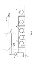
- Figure 1 is a schematic illustration of an industrial drive in connection with which the invention is applied,
- Figure 2 illustrates an arrangement according to the invention, and
- Figure 3 illustrates signals according to the invention.
- Figure 1 is a schematic illustration of an industrial drive in connection with which the invention is applied. A
drive control device 2 is used to provide a start-up instruction to the motors 4. Before start-up, a signal is transmitted from thecontrol device 2 through the start-up alarm circuit 6 to thealarm devices 8, causing an alarm sound signal to be generated at the site of the motors. The placement and operating method of the horns depends on the application and its requirements. For example, the standard EN-1034 referred to above defines the duration of the start-up alarm, a waiting period for staff to move to a safe area, and a start-up readiness period during which start-up may occur. There may be several alarm horns in the same room, controlled by the same device. On the other hand, there may only be one motor and one alarm device if the start-up control is located away from the operating site. - In a solution according to the invention, each alarm horn is doubled, meaning that each location in which the start-up alarm must be audible includes two horns with mutually independent controls. The alarm device comprises several sound sources, half of which are connected to a first chain and the other half connected to a second chain, the first chain being controlled with a first means of control and the second chain being controlled with a second means of control, and each sound source within the first chain forming a pair of alarm horns with one sound source within the second chain. Figure 2 illustrates an embodiment of the invention. In a normal start-up situation, the control output of the machine being started provides a start-
up alarm signal 10 belonging to the start-up sequence. When active, this signal controls theoscillator 12. Theoscillator 12 generates a sequence of pulses in opposite phases with a pulse frequency of approximately 0.5 to 1 second. Two chains controlling alarm horns are connected after the oscillator, the first one controlling thehorns 14 and the second one controlling thehorns 16. Theoutput 18 of theoscillator 12 is conducted to anOR circuit 20 whose output is used to control thehorns 14 chained to the first chain through thefirst bus 15. Thesecond output 22 of theoscillator 12 is inverted in relation to the pulse fromoutput 18. Theoutput 22 is conducted through anAND circuit 23 to anOR circuit 24, the output of which is correspondingly used to control thehorns 16 chained to the second chain through thesecond bus 17. Thesecond input 25 of theAND circuit 23 is taken from the start-up alarm signal, meaning that the output of theAND circuit 23 will only have a signal when the start-up alarm signal is active. Figure 3 illustrates the sequences of pulses K1 and K2 fromoutput 18 andoutput 22 of theoscillator 12. The pulse duration T is equal to the phase difference between the outputs. Therefore, alarm signals having a duration of T are alternately generated fromhorns - Two sound sources forming a pair of alarm horns are preferably installed substantially close to each other. The pair of horns can also be installed within the same enclosure.
- If one of the alarm chains or a horn connected to a chain fails, the horns emit an intermittent sound signal indicating a fault in the alarm system. In such a case, the operation of the alarm device is tested using
test buttons 26 and, correspondingly, 28 arranged for both alarm chains. Whenbutton 26 is pressed, a signal is activated atoutput 30 and conducted to the second input of theOR circuit 20, causing thehorns 14 to generate a continuous alarm sound. Correspondingly, whenbutton 28 is pressed, a signal is activated at the second input of theOR circuit 24, resulting in a continuous alarm sound to be heard from thesecond horns 16. Pressing the test button does not initiate the normal start-up sequence. It only generates a test alarm that applies to each of the alarm chains separately. - According to the invention, a solid alarm signal is generated at the start of the machine start-up sequence. A fault situation is indicated by an intermittent sound, and the operation of the alarm devices is tested using a designated test button for each of the parallel circuits.
- In the above, the invention has been described by reference to certain embodiments. However, the description should not be considered as limiting the scope of patent protection; the embodiments of the invention may vary within the scope of the claims.
Claims (11)
- An arrangement for an industrial drive, such as a paper machine, in which at least one machine (4) or part of machine can be started from a location separate from the machine or part of machine, said arrangement including an alarm device that can be activated before the part of machine is started, characterised in that the alarm device comprises two sound sources (14, 16) and two means for controlling a sound source (18, 20, 22, 23, 24) that can be activated before starting the machine (4) so that the alarm sounds from both sound sources (14, 16) are intermittent and jointly comprise a substantially solid continuous sound.
- An arrangement according to claim 1, characterised in that the sound sources are controlled on the basis of the digital outputs (10) of the machine controls using substantially similar control signals (K1, K2) with a mutual phase difference equal to the duration (T) of the control signal.
- An arrangement according to claim 1 or 2, characterised in that the alarm device comprises several sound sources, half of which are connected to a first chain and the other half connected to a second chain, the first chain being controlled with a first means of control (18, 20) and the second chain being controlled with a second means of control (22, 23, 24), and each sound source (14) within the first chain forming a pair of alarm horns with one sound source (16) within the second chain.
- An arrangement according to any of the claims from 1 to 3, characterised in that two sound sources form a pair of alarm horns installed substantially close to each other.
- An arrangement according to claim 4, characterised in that the sound sources within the pair of alarm horns are fitted within the same enclosure.
- An arrangement according to any of the claims from 1 to 5, characterised in that a fault in one of the sound sources within an alarm device and/or its means of control only affects the alarm sound from the particular sound source, resulting in that the alarm sound produced by the alarm device is intermittent in the case of a fault.
- An arrangement according to any of the claims from 1 to 6, characterised in that the arrangement includes a test button (26, 28) for activating the alarm device.
- An arrangement according to claim 7, characterised in that each of the sound sources within a pair of alarm horns has a designated test button (26, 28) for generating a test alarm.
- An arrangement according to any of the claims from 1 to 8, characterised in that during the start-up of the machine or part of machine, all of the sound sources (14, 16) are activated automatically.
- A method for generating a start-up alarm in an industrial facility such as a paper machine in which a machine or part of machine can be started from a separate location, characterised in that the method involves generating a first (18) and second (22) control signal that are alternately active, conducting the first control signal through a first bus (15) to a first sound source (14) and conducting the second control signal through a second bus (17) to a second sound source (16), resulting in that the first and second sound sources generate an alarm sound that is substantially uninterrupted.
- A method according to claim 10, characterised in that several sound sources daisy-chained with each other are connected to the first and the second bus, correspondingly.
Applications Claiming Priority (1)
| Application Number | Priority Date | Filing Date | Title |
|---|---|---|---|
| FI20050581A FI117255B (en) | 2005-05-31 | 2005-05-31 | Start-up alarm generating arrangement for industrial drive i.e. paper machine, has sound sources and chains controlling sound source such that alarm sounds include substantially solid continuous sound |
Publications (2)
| Publication Number | Publication Date |
|---|---|
| EP1731671A1 true EP1731671A1 (en) | 2006-12-13 |
| EP1731671B1 EP1731671B1 (en) | 2011-04-06 |
Family
ID=34630141
Family Applications (1)
| Application Number | Title | Priority Date | Filing Date |
|---|---|---|---|
| EP06011171A Not-in-force EP1731671B1 (en) | 2005-05-31 | 2006-05-31 | Arrangement and method for starting a machine |
Country Status (6)
| Country | Link |
|---|---|
| US (1) | US7482942B2 (en) |
| EP (1) | EP1731671B1 (en) |
| AT (1) | ATE504696T1 (en) |
| BR (1) | BRPI0601948A (en) |
| DE (1) | DE602006021096D1 (en) |
| FI (1) | FI117255B (en) |
Families Citing this family (1)
| Publication number | Priority date | Publication date | Assignee | Title |
|---|---|---|---|---|
| US9587829B1 (en) | 2013-08-12 | 2017-03-07 | Procom Heating, Inc. | Pre-start indicator for portable heater |
Citations (2)
| Publication number | Priority date | Publication date | Assignee | Title |
|---|---|---|---|---|
| US4266221A (en) * | 1979-09-20 | 1981-05-05 | Hawkins J C | Personnel alarm circuit for industrial machinery |
| US5652566A (en) | 1995-12-15 | 1997-07-29 | Aequitron Medical, Inc. | Alarm system |
Family Cites Families (9)
| Publication number | Priority date | Publication date | Assignee | Title |
|---|---|---|---|---|
| GB1387828A (en) | 1971-07-30 | 1975-03-19 | Anderson Mavor Ltd | Circuit for a prestart warning system |
| GB1586036A (en) * | 1978-04-12 | 1981-03-11 | Dresser Europe Sa | Pre-start warning device for a machine |
| GB2100039B (en) | 1981-05-28 | 1985-11-20 | Wultex Machine | Alarms |
| GB2126025B (en) | 1982-08-14 | 1986-01-15 | Dresser Europe Sa | Power supply system and mining machine incorporating such system |
| DE3624099A1 (en) | 1986-07-17 | 1988-01-21 | Stein Gmbh | Device for audibly warning persons via a radio-frequency information channel |
| US5189388A (en) * | 1991-03-04 | 1993-02-23 | Mosley Judy A | Oil well pump start-up alarm |
| JP3141472B2 (en) | 1991-12-03 | 2001-03-05 | 日本電気株式会社 | Switching control method |
| US5264834A (en) * | 1992-04-20 | 1993-11-23 | Howard Silken | Power equipment warning device |
| DE4418998C1 (en) * | 1994-05-31 | 1995-12-21 | Roland Man Druckmasch | Safety device for a printing machine |
-
2005
- 2005-05-31 FI FI20050581A patent/FI117255B/en not_active IP Right Cessation
-
2006
- 2006-05-30 BR BRPI0601948-0A patent/BRPI0601948A/en not_active IP Right Cessation
- 2006-05-31 EP EP06011171A patent/EP1731671B1/en not_active Not-in-force
- 2006-05-31 US US11/443,261 patent/US7482942B2/en not_active Expired - Fee Related
- 2006-05-31 AT AT06011171T patent/ATE504696T1/en active
- 2006-05-31 DE DE602006021096T patent/DE602006021096D1/en active Active
Patent Citations (2)
| Publication number | Priority date | Publication date | Assignee | Title |
|---|---|---|---|---|
| US4266221A (en) * | 1979-09-20 | 1981-05-05 | Hawkins J C | Personnel alarm circuit for industrial machinery |
| US5652566A (en) | 1995-12-15 | 1997-07-29 | Aequitron Medical, Inc. | Alarm system |
Non-Patent Citations (1)
| Title |
|---|
| "Safety of machinery - Safety requirements for the design and construction of paper making and finishing machines", CEN, EUROPEAN COMMITTEE FOR STANDARDIZATION: EN 1034-1:2000, 17 September 1999 (1999-09-17) |
Also Published As
| Publication number | Publication date |
|---|---|
| US20070008161A1 (en) | 2007-01-11 |
| US7482942B2 (en) | 2009-01-27 |
| FI117255B (en) | 2006-08-15 |
| DE602006021096D1 (en) | 2011-05-19 |
| ATE504696T1 (en) | 2011-04-15 |
| EP1731671B1 (en) | 2011-04-06 |
| BRPI0601948A (en) | 2007-02-21 |
| FI20050581A0 (en) | 2005-05-31 |
Similar Documents
| Publication | Publication Date | Title |
|---|---|---|
| JP4826921B2 (en) | Automatic machine system and wireless communication method thereof | |
| EP1403010B1 (en) | Robot system comprising an operator detection unit | |
| JP2011516365A (en) | Remote observation analysis for elevator equipment | |
| JPH0737310B2 (en) | Elevator monitoring equipment | |
| EP0740278A1 (en) | Alarm device | |
| KR20070049213A (en) | Power-on-Reset of the Elevator Controller | |
| US6778079B2 (en) | Input/output methodology for control reliable interconnection of safety light curtains and other machine safety controls | |
| EP1731671B1 (en) | Arrangement and method for starting a machine | |
| GB2199466A (en) | Monitoring loudspeakers | |
| KR101879385B1 (en) | Signal processing apparatus for vibration supervisory | |
| JP5022736B2 (en) | Passenger conveyor driving device | |
| JP4116099B2 (en) | Safety device for drive unit | |
| JPH1019662A (en) | Self-diagnosis device | |
| JPS61164138A (en) | Method for detecting abnormality at operating section of machine | |
| JPH02271256A (en) | Decision device of rotational speed detector | |
| CN114076852A (en) | Detection mechanism for OSSD signal of safety equipment | |
| JP2008097285A (en) | Plant monitoring and control system | |
| JP2002037561A (en) | Abnormal sound monitoring device for elevator | |
| KR101201471B1 (en) | Bridge Alarm Management Device and Method | |
| KR20120053098A (en) | Robot control system | |
| JP2002312869A (en) | Slope descent object detection device | |
| EP3518265A1 (en) | Switch device | |
| JPH01112398A (en) | Abnormality alarm device | |
| KR200290161Y1 (en) | Checking device for abnormality of robot automatic control device | |
| JP2023086557A (en) | Water supply device |
Legal Events
| Date | Code | Title | Description |
|---|---|---|---|
| PUAI | Public reference made under article 153(3) epc to a published international application that has entered the european phase |
Free format text: ORIGINAL CODE: 0009012 |
|
| AK | Designated contracting states |
Kind code of ref document: A1 Designated state(s): AT BE BG CH CY CZ DE DK EE ES FI FR GB GR HU IE IS IT LI LT LU LV MC NL PL PT RO SE SI SK TR |
|
| AX | Request for extension of the european patent |
Extension state: AL BA HR MK YU |
|
| 17P | Request for examination filed |
Effective date: 20070530 |
|
| AKX | Designation fees paid |
Designated state(s): AT BE BG CH CY CZ DE DK EE ES FI FR GB GR HU IE IS IT LI LT LU LV MC NL PL PT RO SE SI SK TR |
|
| 17Q | First examination report despatched |
Effective date: 20100414 |
|
| GRAP | Despatch of communication of intention to grant a patent |
Free format text: ORIGINAL CODE: EPIDOSNIGR1 |
|
| GRAS | Grant fee paid |
Free format text: ORIGINAL CODE: EPIDOSNIGR3 |
|
| GRAA | (expected) grant |
Free format text: ORIGINAL CODE: 0009210 |
|
| AK | Designated contracting states |
Kind code of ref document: B1 Designated state(s): AT BE BG CH CY CZ DE DK EE ES FI FR GB GR HU IE IS IT LI LT LU LV MC NL PL PT RO SE SI SK TR |
|
| REG | Reference to a national code |
Ref country code: GB Ref legal event code: FG4D |
|
| REG | Reference to a national code |
Ref country code: CH Ref legal event code: EP |
|
| REG | Reference to a national code |
Ref country code: IE Ref legal event code: FG4D |
|
| REF | Corresponds to: |
Ref document number: 602006021096 Country of ref document: DE Date of ref document: 20110519 Kind code of ref document: P |
|
| REG | Reference to a national code |
Ref country code: DE Ref legal event code: R096 Ref document number: 602006021096 Country of ref document: DE Effective date: 20110519 |
|
| REG | Reference to a national code |
Ref country code: SE Ref legal event code: TRGR |
|
| REG | Reference to a national code |
Ref country code: NL Ref legal event code: VDEP Effective date: 20110406 |
|
| PG25 | Lapsed in a contracting state [announced via postgrant information from national office to epo] |
Ref country code: SI Free format text: LAPSE BECAUSE OF FAILURE TO SUBMIT A TRANSLATION OF THE DESCRIPTION OR TO PAY THE FEE WITHIN THE PRESCRIBED TIME-LIMIT Effective date: 20110406 |
|
| LTIE | Lt: invalidation of european patent or patent extension |
Effective date: 20110406 |
|
| PG25 | Lapsed in a contracting state [announced via postgrant information from national office to epo] |
Ref country code: LT Free format text: LAPSE BECAUSE OF FAILURE TO SUBMIT A TRANSLATION OF THE DESCRIPTION OR TO PAY THE FEE WITHIN THE PRESCRIBED TIME-LIMIT Effective date: 20110406 Ref country code: PT Free format text: LAPSE BECAUSE OF FAILURE TO SUBMIT A TRANSLATION OF THE DESCRIPTION OR TO PAY THE FEE WITHIN THE PRESCRIBED TIME-LIMIT Effective date: 20110808 |
|
| PG25 | Lapsed in a contracting state [announced via postgrant information from national office to epo] |
Ref country code: BE Free format text: LAPSE BECAUSE OF FAILURE TO SUBMIT A TRANSLATION OF THE DESCRIPTION OR TO PAY THE FEE WITHIN THE PRESCRIBED TIME-LIMIT Effective date: 20110406 Ref country code: LV Free format text: LAPSE BECAUSE OF FAILURE TO SUBMIT A TRANSLATION OF THE DESCRIPTION OR TO PAY THE FEE WITHIN THE PRESCRIBED TIME-LIMIT Effective date: 20110406 Ref country code: FI Free format text: LAPSE BECAUSE OF FAILURE TO SUBMIT A TRANSLATION OF THE DESCRIPTION OR TO PAY THE FEE WITHIN THE PRESCRIBED TIME-LIMIT Effective date: 20110406 Ref country code: IS Free format text: LAPSE BECAUSE OF FAILURE TO SUBMIT A TRANSLATION OF THE DESCRIPTION OR TO PAY THE FEE WITHIN THE PRESCRIBED TIME-LIMIT Effective date: 20110806 Ref country code: ES Free format text: LAPSE BECAUSE OF FAILURE TO SUBMIT A TRANSLATION OF THE DESCRIPTION OR TO PAY THE FEE WITHIN THE PRESCRIBED TIME-LIMIT Effective date: 20110717 Ref country code: GR Free format text: LAPSE BECAUSE OF FAILURE TO SUBMIT A TRANSLATION OF THE DESCRIPTION OR TO PAY THE FEE WITHIN THE PRESCRIBED TIME-LIMIT Effective date: 20110707 Ref country code: CY Free format text: LAPSE BECAUSE OF FAILURE TO SUBMIT A TRANSLATION OF THE DESCRIPTION OR TO PAY THE FEE WITHIN THE PRESCRIBED TIME-LIMIT Effective date: 20110406 |
|
| PG25 | Lapsed in a contracting state [announced via postgrant information from national office to epo] |
Ref country code: MC Free format text: LAPSE BECAUSE OF NON-PAYMENT OF DUE FEES Effective date: 20110531 Ref country code: NL Free format text: LAPSE BECAUSE OF FAILURE TO SUBMIT A TRANSLATION OF THE DESCRIPTION OR TO PAY THE FEE WITHIN THE PRESCRIBED TIME-LIMIT Effective date: 20110406 |
|
| REG | Reference to a national code |
Ref country code: CH Ref legal event code: PL |
|
| PG25 | Lapsed in a contracting state [announced via postgrant information from national office to epo] |
Ref country code: CZ Free format text: LAPSE BECAUSE OF FAILURE TO SUBMIT A TRANSLATION OF THE DESCRIPTION OR TO PAY THE FEE WITHIN THE PRESCRIBED TIME-LIMIT Effective date: 20110406 Ref country code: CH Free format text: LAPSE BECAUSE OF NON-PAYMENT OF DUE FEES Effective date: 20110531 Ref country code: LI Free format text: LAPSE BECAUSE OF NON-PAYMENT OF DUE FEES Effective date: 20110531 Ref country code: EE Free format text: LAPSE BECAUSE OF FAILURE TO SUBMIT A TRANSLATION OF THE DESCRIPTION OR TO PAY THE FEE WITHIN THE PRESCRIBED TIME-LIMIT Effective date: 20110406 |
|
| PLBE | No opposition filed within time limit |
Free format text: ORIGINAL CODE: 0009261 |
|
| STAA | Information on the status of an ep patent application or granted ep patent |
Free format text: STATUS: NO OPPOSITION FILED WITHIN TIME LIMIT |
|
| PG25 | Lapsed in a contracting state [announced via postgrant information from national office to epo] |
Ref country code: RO Free format text: LAPSE BECAUSE OF FAILURE TO SUBMIT A TRANSLATION OF THE DESCRIPTION OR TO PAY THE FEE WITHIN THE PRESCRIBED TIME-LIMIT Effective date: 20110406 Ref country code: PL Free format text: LAPSE BECAUSE OF FAILURE TO SUBMIT A TRANSLATION OF THE DESCRIPTION OR TO PAY THE FEE WITHIN THE PRESCRIBED TIME-LIMIT Effective date: 20110406 Ref country code: SK Free format text: LAPSE BECAUSE OF FAILURE TO SUBMIT A TRANSLATION OF THE DESCRIPTION OR TO PAY THE FEE WITHIN THE PRESCRIBED TIME-LIMIT Effective date: 20110406 Ref country code: DK Free format text: LAPSE BECAUSE OF FAILURE TO SUBMIT A TRANSLATION OF THE DESCRIPTION OR TO PAY THE FEE WITHIN THE PRESCRIBED TIME-LIMIT Effective date: 20110406 |
|
| REG | Reference to a national code |
Ref country code: IE Ref legal event code: MM4A |
|
| 26N | No opposition filed |
Effective date: 20120110 |
|
| GBPC | Gb: european patent ceased through non-payment of renewal fee |
Effective date: 20110706 |
|
| PG25 | Lapsed in a contracting state [announced via postgrant information from national office to epo] |
Ref country code: IE Free format text: LAPSE BECAUSE OF NON-PAYMENT OF DUE FEES Effective date: 20110531 |
|
| REG | Reference to a national code |
Ref country code: DE Ref legal event code: R097 Ref document number: 602006021096 Country of ref document: DE Effective date: 20120110 |
|
| PG25 | Lapsed in a contracting state [announced via postgrant information from national office to epo] |
Ref country code: GB Free format text: LAPSE BECAUSE OF NON-PAYMENT OF DUE FEES Effective date: 20110706 |
|
| PG25 | Lapsed in a contracting state [announced via postgrant information from national office to epo] |
Ref country code: LU Free format text: LAPSE BECAUSE OF NON-PAYMENT OF DUE FEES Effective date: 20110531 |
|
| PG25 | Lapsed in a contracting state [announced via postgrant information from national office to epo] |
Ref country code: BG Free format text: LAPSE BECAUSE OF FAILURE TO SUBMIT A TRANSLATION OF THE DESCRIPTION OR TO PAY THE FEE WITHIN THE PRESCRIBED TIME-LIMIT Effective date: 20110706 |
|
| PG25 | Lapsed in a contracting state [announced via postgrant information from national office to epo] |
Ref country code: TR Free format text: LAPSE BECAUSE OF FAILURE TO SUBMIT A TRANSLATION OF THE DESCRIPTION OR TO PAY THE FEE WITHIN THE PRESCRIBED TIME-LIMIT Effective date: 20110406 |
|
| PG25 | Lapsed in a contracting state [announced via postgrant information from national office to epo] |
Ref country code: HU Free format text: LAPSE BECAUSE OF FAILURE TO SUBMIT A TRANSLATION OF THE DESCRIPTION OR TO PAY THE FEE WITHIN THE PRESCRIBED TIME-LIMIT Effective date: 20110406 |
|
| PGFP | Annual fee paid to national office [announced via postgrant information from national office to epo] |
Ref country code: AT Payment date: 20140513 Year of fee payment: 9 Ref country code: DE Payment date: 20140521 Year of fee payment: 9 Ref country code: IT Payment date: 20140527 Year of fee payment: 9 Ref country code: FR Payment date: 20140527 Year of fee payment: 9 Ref country code: SE Payment date: 20140520 Year of fee payment: 9 |
|
| REG | Reference to a national code |
Ref country code: DE Ref legal event code: R119 Ref document number: 602006021096 Country of ref document: DE |
|
| REG | Reference to a national code |
Ref country code: AT Ref legal event code: MM01 Ref document number: 504696 Country of ref document: AT Kind code of ref document: T Effective date: 20150531 |
|
| PG25 | Lapsed in a contracting state [announced via postgrant information from national office to epo] |
Ref country code: IT Free format text: LAPSE BECAUSE OF NON-PAYMENT OF DUE FEES Effective date: 20150531 |
|
| REG | Reference to a national code |
Ref country code: SE Ref legal event code: EUG |
|
| REG | Reference to a national code |
Ref country code: FR Ref legal event code: ST Effective date: 20160129 |
|
| PG25 | Lapsed in a contracting state [announced via postgrant information from national office to epo] |
Ref country code: SE Free format text: LAPSE BECAUSE OF NON-PAYMENT OF DUE FEES Effective date: 20150601 Ref country code: AT Free format text: LAPSE BECAUSE OF NON-PAYMENT OF DUE FEES Effective date: 20150531 |
|
| PG25 | Lapsed in a contracting state [announced via postgrant information from national office to epo] |
Ref country code: DE Free format text: LAPSE BECAUSE OF NON-PAYMENT OF DUE FEES Effective date: 20151201 |
|
| PG25 | Lapsed in a contracting state [announced via postgrant information from national office to epo] |
Ref country code: FR Free format text: LAPSE BECAUSE OF NON-PAYMENT OF DUE FEES Effective date: 20150601 |