EP1731322A2 - Image generating apparatus - Google Patents
Image generating apparatus Download PDFInfo
- Publication number
- EP1731322A2 EP1731322A2 EP06251519A EP06251519A EP1731322A2 EP 1731322 A2 EP1731322 A2 EP 1731322A2 EP 06251519 A EP06251519 A EP 06251519A EP 06251519 A EP06251519 A EP 06251519A EP 1731322 A2 EP1731322 A2 EP 1731322A2
- Authority
- EP
- European Patent Office
- Prior art keywords
- head portion
- pressing member
- head
- spring
- spring fixing
- Prior art date
- Legal status (The legal status is an assumption and is not a legal conclusion. Google has not performed a legal analysis and makes no representation as to the accuracy of the status listed.)
- Granted
Links
- 230000008878 coupling Effects 0.000 claims description 11
- 238000010168 coupling process Methods 0.000 claims description 11
- 238000005859 coupling reaction Methods 0.000 claims description 11
- 239000002184 metal Substances 0.000 description 3
- 238000010586 diagram Methods 0.000 description 1
- 239000011347 resin Substances 0.000 description 1
- 229920005989 resin Polymers 0.000 description 1
- 230000000452 restraining effect Effects 0.000 description 1
Images




Classifications
-
- B—PERFORMING OPERATIONS; TRANSPORTING
- B41—PRINTING; LINING MACHINES; TYPEWRITERS; STAMPS
- B41J—TYPEWRITERS; SELECTIVE PRINTING MECHANISMS, i.e. MECHANISMS PRINTING OTHERWISE THAN FROM A FORME; CORRECTION OF TYPOGRAPHICAL ERRORS
- B41J25/00—Actions or mechanisms not otherwise provided for
- B41J25/304—Bodily-movable mechanisms for print heads or carriages movable towards or from paper surface
- B41J25/312—Bodily-movable mechanisms for print heads or carriages movable towards or from paper surface with print pressure adjustment mechanisms, e.g. pressure-on-the paper mechanisms
Definitions
- the present invention relates to an image generating apparatus, and more particularly, it relates to an image generating apparatus comprising a print head.
- thermal printer is generally known as an image generating apparatus performing printing by pressing a print head against a platen provided in the form of a roll or the like.
- Japanese Patent Laying-Open No. 6-122246 (1994 ) discloses such a thermal printer (thermal transfer printer).
- the aforementioned Japanese Patent Laying-Open No. 6-122246 discloses a thermal printer pressing a print head against a platen roller by urging the printing head portion downward with a spring.
- the conventional thermal printer disclosed in the aforementioned Japanese Patent Laying-Open No. 6-122246 is provided with no mechanical portion for automatically separating the print head from the platen roller, and hence it is disadvantageously necessary to manually lift up the print head, in order to separate the same from the platen roller.
- a print head printer provided with a mechanical portion for automatically separating a print head from a printer is proposed in general, as disclosed in Japanese Patent Laying-Open No. 5-309905 (1993 ), Japanese Patent Laying-Open No. 6-15852 (1994 ), Japanese Patent Laying-Open No. 6-191066 (1994 ) or Japanese Patent Laying-Open No. 9-188027 (1997 ), for example.
- the aforementioned Japanese Patent Laying-Open No. 5-309905 discloses a print head, pressed against a platen with urging force of a spring, provided with a mechanical portion (head portion retraction means) formed by a gear wheel, a follower plate and an arm for moving the print head oppositely to the platen against the urging force of the spring.
- Each of the aforementioned Japanese Patent Laying-Open No. 6-15852 , Japanese Patent Laying-Open No. 6-191066 and Japanese Patent Laying-Open No. 9-188027 discloses a thermal printer, having a print head mounted on an arm synchronously rotating with a cam, capable of pressing and separating the print head against and from a platen roller by rotating the cam thereby rotating the arm.
- coupling arms coupling a support shaft rotatably supporting the print head and the print head with each other are provided on both ends of the print head for rotating the print head about the support shaft by engaging the coupling arms with the arm synchronously rotating with the cam.
- the arm presses only one of the coupling arms of the print head and applies pressing force to only the corresponding end of the print head if the thermal printer has only a single cam since the arm engaging with the cam engages with the coupling arms, and hence the print head cannot be uniformly pressed against the platen roller.
- two cams must be provided on both ends of the print head for pressing both ends of a coupling portion of the print head.
- the cams must be arranged on both ends of the print head, and arms synchronously rotating with the cams must also be provided on both ends of the print head. Consequently, the number of components is disadvantageously increased in the conventional thermal printer disclosed in each of the aforementioned Japanese Patent Laying-Open No. 6-15852 , Japanese Patent Laying-Open No. 6-191066 and Japanese Patent Laying-Open No. 9-188027 , although the print head can be automatically separated from the platen roller. Further, the size of the thermal printer is disadvantageously increased due to the cams arranged on both ends of the print head.
- the present invention has been proposed in order to solve the aforementioned problems, and an object of the present invention is to provide a downsizable image generating apparatus capable of reducing the number of components.
- An image generating apparatus comprises a platen roller, a print head, opposed to the platen roller, having a head portion pressed against the platen roller, a head portion pressing member provided independently of the print head and mounted on a rotary shaft for pressing the head portion of the print head against the platen roller and a gear arranged on a first end of the rotary shaft for rotating the head portion, while the head portion pressing member is provided with a gear portion meshing with the gear and a first engaging portion, and the head portion is provided with a second engaging portion engaging with the first engaging portion of the head portion pressing member upon upward rotation of the head portion pressing member.
- the gear for rotating the head portion pressing member mounted on the rotary shaft by transmitting driving force from a drive source thereto is arranged on the first end of the rotary shaft while the gear portion meshing with the gear is formed on the head portion pressing member so that the driving force can be transmitted from the drive source to the head portion pressing member through the gear, whereby the upper portion of the print head can be pressed with the head portion pressing member by rotating the head portion pressing member through the rotary shaft.
- the print head can be uniformly pressed against the platen roller with the head portion pressing member through the rotary shaft with the gear arranged on the first end of the rotary shaft, whereby the image generating apparatus can be inhibited from applying nonuniform pressing force against the print head although the gear is not arranged on each end of the rotary shaft.
- the gear for rotating the head portion pressing member may not be arranged on each side of the rotary shaft, whereby the number of components can be reduced.
- the head portion pressing member is provided with the first engaging portion and the head portion of the print head is provided with the second engaging portion engaging with the first engaging portion of the head portion pressing member upon upward rotation of the head portion pressing member so that the head portion of the print head can be rotated upward by engaging the second engaging portion mounted on the head portion of the print head and the first engaging portion of the head portion pressing member with each other upon upward rotation of the head portion pressing member, whereby the head portion of the print head can be separated from the platen roller by upwardly rotating the head portion pressing member. Therefore, no mechanical portion may be additionally provided for separating the head portion of the print head from the platen roller, whereby the number of components can be reduced also according to this structure.
- the gear for rotating the head portion pressing member mounted on the rotary shaft may not be arranged on each end of the rotary shaft and no mechanical portion may be additionally provided for separating the head portion of the print head from the platen roller, whereby the image generating apparatus can be downsized.
- the print head preferably includes a spring fixing member, mounted on the head portion, having a first spring fixing portion and a second spring fixing portion arranged in the axial direction of the platen roller at a prescribed interval as well as a first spring member and a second spring member fixed to the first spring fixing portion and the second spring fixing portion of the spring fixing member respectively for urging the head portion toward the platen roller
- the head portion pressing member preferably includes a first head portion pressing member for generating urging force in the spring member by pressing the first spring member through rotation following driving of the gear and a second head portion pressing member for generating urging force in the second spring member by pressing the second spring member through corotation with the first head portion pressing member.
- the print head can be urged toward the platen roller with the first and second spring members, whereby the head portion of the print head can be stably pressed against the platen roller as compared with a case of urging the head portion of the print head toward the platen roller with urging force of a single spring member.
- the first head portion pressing member is preferably integrally provided with the gear portion meshing with the gear. According to this structure, the number of components can be inhibited from increase despite the gear portion provided on the first head portion pressing member.
- the first engaging portion is preferably provided on either the first head portion pressing member or the second head portion pressing member
- the second engaging portion is preferably provided on either the first spring fixing portion or the second spring fixing portion corresponding to the first or second head portion pressing member provided with the first engaging portion.
- the first engaging portion preferably includes a protrusion integrally provided on the second head portion to protrude in the extensional direction of the rotary shaft
- the second engaging portion preferably includes a notch integrally provided on the second spring fixing portion of the spring fixing member for engaging with the protrusion of the second head portion pressing member upon upward rotation of the second head portion pressing member.
- the second spring fixing portion preferably includes an upright wall formed by partially uprighting the spring fixing member formed by a plate body, and the notch is preferably formed on the upright wall.
- the upright wall having the notch can be easily integrally formed on the second spring fixing portion by partially uprighting the spring fixing member formed by a plate body.
- a chamfer is preferably formed on the opening side of the notch. According to this structure, the opening space of the notch is increased on the opening side, whereby the protrusion of the second head portion pressing member can be easily engaged with the notch.
- the first head portion pressing member and the second head portion pressing member preferably press the first spring member and the second spring member respectively while the engagement between the first engaging portion and the second engaging portion is canceled.
- the operation of the first engaging portion of the second head portion pressing member is not restrained by the second engaging portion of the second spring member when the first and second head portion pressing members press the first and second spring members respectively, whereby the first and second spring members can be easily pressed with the first and second head portion pressing members respectively.
- the first spring member and the second spring member may be torsion coil springs.
- the print head preferably further includes a support shaft and an arm coupling the support shaft and the head portion with each other and is preferably rotatable about the support shaft, the head portion pressing member preferably rotates in a first direction thereby rotating the print head for pressing and moving the head portion toward the platen roller in printing, and the head portion pressing member preferably rotates in a second direction opposite to the first direction upon engagement between the first engaging portion and the second engaging portion thereby rotating the print head for separating the head portion from the platen roller in nonprinting.
- the print head can be easily rotated about the support shaft by rotating the head portion pressing member.
- An image generating apparatus comprises a platen roller, a print head, opposed to the platen roller, having a head portion pressed against the platen roller, a head portion pressing member provided independently of the print head and mounted on a rotary shaft for pressing the head portion of the print head against the platen roller and a gear arranged on a first end of the rotary shaft for rotating the head portion by transmitting driving force of a motor to the head portion pressing member
- the print head further includes a spring fixing member, mounted on the head portion, having a first spring fixing portion and a second spring fixing portion arranged in the axial direction of the platen roller at a prescribed interval as well as a first spring member and a second spring member fixed to the first spring fixing portion and the second spring fixing portion of the spring fixing member respectively for urging the head portion toward the platen roller
- the head portion pressing member further includes a first head portion pressing member for generating urging force in the spring member by pressing the first spring member through rotation following driving of the gear and a second head portion pressing
- the gear for rotating the head portion pressing member mounted on the rotary shaft by transmitting the driving force from the motor thereto is arranged on the first end of the rotary shaft while the gear portion meshing with the gear is formed on the first head portion pressing member constituting the head portion pressing member so that the driving force of the motor can be transmitted to the head portion pressing member through the gear, whereby the upper portion of the print head can be pressed with the head portion pressing member by rotating the head portion pressing member through the rotary shaft.
- the print head can be uniformly pressed against the platen roller with the head portion pressing member through the rotary shaft with the gear arranged on the first end of the rotary shaft, whereby the image generating apparatus can be inhibited from applying nonuniform pressing force against the print head although the gear is not arranged on each end of the rotary shaft.
- the gear for rotating the head portion pressing member may not be arranged on each side of the rotary shaft, whereby the number of components can be reduced.
- the second head portion pressing member constituting the head portion pressing member is provided with the protrusion protruding in the extensional direction of the rotary shaft and the second spring fixing portion of the spring fixing member mounted on the head portion of the print head is provided with the notch engaging with the protrusion of the second head portion pressing member upon upward rotation of the second head portion pressing member so that the head portion of the print head can be rotated upward by engaging the notch of the second spring fixing portion of the spring fixing member mounted on the head portion of the print head and the protrusion of the second head portion pressing member with each other upon upward rotation of the head portion pressing member, whereby the head portion of the print head can be separated from the platen roller by upwardly rotating the head portion pressing member.
- no mechanical portion may be additionally provided for separating the head portion of the print head from the platen roller, whereby the number of components can be reduced also according to this structure.
- the gear for rotating the head portion pressing member mounted on the rotary shaft may not be arranged on each end of the rotary shaft and no mechanical portion may be additionally provided for separating the head portion of the print head from the platen roller, whereby the image generating apparatus can be downsized.
- the spring fixing member having the first and second spring fixing portions arranged in the axial direction of the platen roller at the prescribed interval is mounted on the head portion of the print head and the first and second spring members urging the head portion toward the platen roller are fixed to the first and second spring fixing portions of the spring fixing member respectively for generating urging force in the first spring member by pressing the first spring member with the first head portion pressing member rotating following driving of the gear and generating urging force in the second spring member by pressing the second spring member with the second head portion pressing member corotating with the first head portion pressing member, whereby the print head can be urged toward the platen roller with the first and second spring members.
- the head portion of the print head can be stably pressed against the platen roller as compared with a case of urging the head portion of the print head toward the platen roller with urging force of a single spring member.
- the gear portion meshing with the gear is integrally provided on the first head portion pressing member, whereby the number of components can be inhibited from increase despite the gear provided on the first head portion pressing member.
- the protrusion protruding in the extensional direction of the rotary shaft is integrally provided on the second head portion pressing member and the engaging portion engaging with the protrusion of the second head portion pressing member is integrally provided on the second spring fixing portion of the spring fixing member, whereby the number of components can be inhibited from increase despite the protrusion and the notch provided on the second head portion pressing member and the second spring fixing portion of the spring fixing member respectively.
- the print head can be also employed for printing pictures, in addition to characters.
- the first engaging portion is preferably provided on either the first head portion pressing member or the second head portion pressing member
- the second engaging portion is preferably provided on either the first spring fixing portion or the second spring fixing portion corresponding to the first or second head portion pressing member provided with the first engaging portion.
- the second spring fixing portion preferably includes an upright wall formed by partially uprighting the spring fixing member formed by a plate body, and the notch is preferably formed on the upright wall. According to this structure, the upright wall having the notch can be easily integrally formed on the second spring fixing portion by partially uprighting the spring fixing member formed by a plate body.
- a chamfer is preferably formed on the opening side of the notch. According to this structure, the opening space of the notch is increased on the opening side, whereby the protrusion of the second head portion pressing member can be easily engaged with the notch.
- the first head portion pressing member and the second head portion pressing member preferably press the first spring member and the second spring member respectively while the engagement between the first engaging portion and the second engaging portion is canceled.
- the operation of the first engaging portion of the second head portion pressing member is not restrained by the second engaging portion of the second spring member when the first and second head portion pressing members press the first and second spring members respectively, whereby the first and second spring members can be easily pressed with the first and second head portion pressing members respectively.
- the first spring member and the second spring member may be torsion coil springs.
- the print head preferably further includes a support shaft and an arm coupling the support shaft and the head portion with each other and is preferably rotatable about the support shaft, the head portion pressing member preferably rotates in a first direction thereby rotating the print head for pressing and moving the head portion toward the platen roller in printing, and the head portion pressing member preferably rotates in a second direction opposite to the first direction upon engagement between the first engaging portion and the second engaging portion thereby rotating the print head for separating the head portion from the platen roller in nonprinting.
- the print head can be easily rotated about the support shaft by rotating the head portion pressing member.
- thermal transfer printer First, the structure of a thermal transfer printer according to this embodiment is described with reference to Figs. 1 to 8.
- the embodiment of the present invention is applied to the thermal transfer printer, an exemplary image generating apparatus.
- the thermal transfer printer comprises a metal chassis 1, a print head 2 for printing, a platen roller 3, two platen roller bearings 4, a metal support rod 5, two head portion pressing members 6a and 6b, a resin drive gear 7, a motor 8 (see Fig. 2), a motor bracket 9 and an intermediate gear 10.
- the support rod 5 is an example of the "rotary shaft” in the present invention
- the drive gear 7 is an example of the "gear” in the present invention.
- the chassis 1 has first and second side surfaces 1a and 1b opposed to each other.
- the first and second side surfaces 1a and 1b of the chassis 1 are provided with support holes 1c for rotatably supporting the support rod 5 respectively.
- An ink sheet receiving hole 1d is provided on the second side surface 1b of the chassis 1, for receiving an ink sheet (not shown).
- the two platen roller bearings 4 are mounted on the first and second side surfaces 1a and 1b of the chassis 1 respectively, for rotatably supporting the platen roller 3.
- Support portions 5a are provided on both ends of the support rod 5 respectively.
- the support portions 5a of the support rod 5 are fitted into the support holes 1c provided on the first and second side surfaces 1a and 1b of the chassis 1 respectively.
- head portion pressing members 6a and 6b are mounted on both ends of the support rod 5 respectively in an unidling manner.
- D-shaped insert portions 5b are provided around both ends of the support rod 5 respectively, as shown in Figs. 4 and 5.
- the two head portion pressing members 6a and 6b are formed with D-shaped receiving holes 61a and 61b receiving the insert portions 5b provided around both ends of the support rod 5 respectively.
- the support rod 5 as well as the second head portion pressing member 6b rotate upon rotation of the first head portion pressing member 6a.
- the head portion pressing members 6a and 6b are arranged on the first and second side surfaces 1a and 1b of the chassis 1 respectively, as shown in Figs. 1 and 2.
- the first head portion pressing member 6a is integrally formed with a pressing portion 62a and a gear portion 63a, as shown in Fig. 4.
- the second head portion pressing member 6b is integrally formed with a pressing portion 62b and a protrusion 63b protruding from the pressing portion 62b in the extensional direction of the support rod 5, as shown in Fig. 5.
- the protrusion 63b is an example of the "first engaging portion" in the present invention.
- the print head 2 has a pair of support shafts 2a, a head portion 2b opposed to the platen roller 3 (see Figs. 1 and 2) and a pair of arms 2c coupling the support shafts 2a and the head portion 2b with each other.
- This print head 2 is rotatable about the support shafts 2a.
- the pair of support shafts 2a of the print head 2 are rotatably mounted on the first and second side surfaces 1a and 1b of the chassis 1 respectively.
- first and second torsion coil springs 2d and 2e for urging the head portion 2b toward the platen roller 3 are arranged on the upper portion of the head portion 2b in regions corresponding to the first and second head portion pressing members 6a and 6b (see Figs. 1 and 2) respectively.
- a metal spring fixing member 2f formed by a plate body consisting of first and second spring fixing portions 2g and 2h is mounted on the upper portion of the head portion 2b with a screw 2i.
- the first and second spring fixing portions 2g and 2h of the spring fixing member 2f are arranged in the axial direction of the platen roller 3 at a prescribed interval.
- the first and second spring fixing portions 2g and 2h are formed with an uprighted spring fixing section 23g and an upright wall-shaped engaging portion 23h, also serving as a spring fixing section, opposed to each other respectively.
- the first and second torsion coil springs 2d and 2e are fixed to the first and second spring fixing portions 2g and 2h of the spring fixing member 2f respectively.
- the first spring fixing portion 2g of the spring fixing member 2f is provided with a stop portion 21g and a protrusion 22g, as shown in Figs. 6 and 7.
- the second spring fixing portion 2h of the spring fixing member 2f is also provided with a stop portion 21h and a protrusion 22h.
- the first torsion coil spring 2d is an example of the "first spring member” in the present invention
- the second torsion coil spring 2e is an example of the "second spring member” in the present invention.
- the first torsion coil spring 2d has a first end 21d pressed by the pressing portion 62a of the first head portion pressing member 6a upon downward rotation of the first head portion pressing member 6a and a second end 22d transmitting urging force resulting from the pressed first end 21d to the head portion 2b, as shown in Figs. 2, 6 and 7.
- the second torsion coil spring 2e has a first end 21e pressed by the pressing portion 62b of the second head portion pressing member 6b upon downward rotation of the second head portion pressing member 6b and a second end 22e transmitting urging force resulting from the pressed first end 21e to the head portion 2b.
- the head portion 2b is pressed against the platen roller 3 due to the urging force transmitted thereto from the torsion coil springs 2d and 2e.
- the first end 21d of the first torsion coil spring 2d is stopped on the stop portion 21g of the spring fixing member 2f, while the second end 22d thereof is fixed to the protrusion 22g of the spring fixing member 2f.
- the first end 21e of the second torsion coil spring 2e is stopped on the stop portion 21h of the spring fixing member 2f, while the second end 22e thereof is fixed to the protrusion 22h of the spring fixing member 2f.
- the engaging portion 23h having a notch 24h engaging with the protrusion 63b of the second head portion pressing member 6b is integrally formed on the second spring fixing portion 2h of the spring fixing member 2f by partially uprighting the spring fixing member 2f, as shown in Fig. 8.
- the protrusion 63b of the second head portion pressing member 6b and the notch 24h of the second spring fixing portion 2h engage with each other upon upward rotation of the second head portion pressing member 6b, thereby upwardly rotating the head portion 2b. Consequently, the head portion 2b having been pressed against the platen roller 3 (see Figs. 1 and 2) is separated from the platen roller 3 upon rotation of the second head portion pressing member 6b.
- a chamfer 25h is formed on the opening side of the notch 24h, in order to simplify the engagement with the protrusion 63b.
- the engaging portion 23h is an example of the "second engaging portion" in the present invention.
- the drive gear 7 and the intermediate gear 10 are provided for rotating the head portion pressing members 6a and 6b by transmitting driving force of the motor 8 thereto, as shown in Figs. 1 and 2.
- the drive gear 7 and the intermediate gear 10 are mounted only on the first side surface 1a of the chassis 1.
- the motor 8 is mounted on the first side surface 1a of the chassis 1 through the motor bracket 9.
- a small diameter gear portion 7a of the drive gear 7 meshes with the gear portion 63a of the first head portion pressing member 6a, while a large diameter gear portion 7b of the drive gear 7 meshes with a small diameter gear 10a of the intermediate gear 10.
- a large diameter gear 10b of the intermediate gear 10 meshes with a motor gear 8a of the motor 8.
- the head portion 2b of the print head 2 is held on a spaced position with respect to the platen roller 3, as shown in Figs. 9 and 10.
- the protrusion 63b of the second head portion pressing member 6b engages with the notch 24h of the engaging portion 23h of the second spring fixing portion 2h provided on the upper portion of the head portion 2b as shown in Fig. 10, thereby restraining the head portion 2b from rotation along arrow B in Fig. 10.
- the head portion 2b having been restrained from rotating along arrow B by the protrusion 63b, is also rotated along arrow B due to rotation of the protrusion 63b of the second head portion pressing member 6b along arrow A.
- the head portion 2b is moved toward the platen roller 3 (press side), as shown in Figs. 13 and 14.
- the direction of arrow A is an example of the "first direction" in the present invention.
- the head portion pressing members 6a and 6b are further rotated along arrow A.
- the pressing portion 62a of the first head portion pressing member 6a presses the first end 21d of the first torsion coil spring 2d of the print head 2.
- the pressing portion 62b of the second head portion pressing member 6b presses the first end 21e of the second torsion coil spring 2e of the print head 2.
- urging force is generated in the torsion coil springs 2d and 2e and transmitted to the head portion 2b through the second ends 22d and 22e of the torsion coil springs 2d and 2e.
- the head portion 2b is urged toward the platen roller 3.
- the engagement between the protrusion 63b of the second head portion pressing member 6b and the notch 24h of the engaging portion 23h of the spring fixing member 2f is canceled.
- the head portion 2b is in the state urged toward the platen roller 3.
- the motor 8 (see Fig. 2) is so driven that the driving force thereof is transmitted to the gear portion 63a of the first head portion pressing member 6a through the intermediate gear 10 and the drive gear 7, thereby rotating the first head portion pressing member 6a about the support rod 5 along arrow C in Fig. 13.
- the first and second head portion pressing members 6a and 6b remain unidling with respect to the support rod 5, whereby the second head portion pressing member 6b is also rotated along arrow C in Fig. 14.
- the head portion 2b is released from the force urging the same toward the platen roller 3 through the torsion coil springs 2d and 2e pressed by the head portion pressing members 6a and 6b.
- the protrusion 63b of the second head portion pressing member 6b engages with the notch 24h of the engaging portion 23h of the second spring fixing portion 2h of the spring fixing member 2f mounted on the head portion 2b.
- the direction of arrow C is an example of the "second direction" in the present invention.
- the print head 2 is also lifted up and rotated along arrow D in Fig. 12 following this rotation of the head portion pressing members 6a and 6b along arrow C in Fig. 14, due to the engagement between the protrusion 63b of the second head portion pressing member 6b and the notch 24h of the engaging portion 23h of the spring fixing member 2f mounted on the head portion 2b.
- the head portion 2b is separated from the platen roller 3.
- the head portion pressing members 6a and 6b are further rotated along arrow C so that the print head 2 is also rotated along arrow D and moved to the spaced position with respect to the platen roller 3, as shown in Fig. 10.
- This spaced position of the print head 2 corresponds to the initial state of the operation of pressing the head portion 2b against the platen roller 3.
- the print head 2 is moved from the position urged toward the platen roller 3 (see Fig. 14) to the spaced position where the head portion 2b is separated from the platen roller 3 (see Fig. 10).
- the drive gear 7 is arranged on the first end of the support rod 5 for rotating the head portion pressing members 6a and 6b mounted on the support rod 5 by transmitting the driving force of the motor 8 thereto and the gear portion 63a meshing with the drive gear 7 is formed on the first head portion pressing member 6a so that the driving force of the motor 8 can be transmitted to the head portion pressing members 6a and 6b through the drive gear 7, whereby the upper portion of the head portion 2b of the print head 2 can be pressed with the head portion pressing members 6a and 6b by rotating the same through the support rod 5.
- the print head 2 can be uniformly pressed against the platen roller 3 with the head portion pressing members 6a and 6b through the support rod 5 with the gear portion 63a arranged on the first end of the support rod 5, whereby the thermal transfer printer can be inhibited from applying nonuniform pressing force against the print head 2 although the drive gear 7 is not arranged on each end of the support rod 5.
- the drive gear 7 for rotating the head portion pressing members 6a and 6b may not be arranged on each side of the support rod 5, whereby the number of components can be reduced.
- the second head portion pressing member 6b is provided with the protrusion protruding in the extensional direction of the support rod 5 while the second spring fixing portion 2h of the spring fixing member 2f mounted on the head portion 2b of the print head 2 is provided with the notch 24h engaging with the protrusion 63b of the second head portion pressing member 6b upon upward rotation of the second head portion pressing member 6b so that the head portion 2b of the print head 2 can be upwardly rotated due to the engagement between the notch 24h of the second spring fixing portion 2h of the spring fixing member 2f mounted on the head portion 2b of the print head 2 and the protrusion 63b of the second head portion pressing member 6b upon upward rotation of the second head portion pressing member 6b, whereby the head portion 2b of the print head 2 can be separated from the platen roller 3 through the upward rotation of the second head portion pressing member 6b.
- no mechanical portion may be additionally provided for separating the head portion 2b of the print head 2 from the platen roller 3, whereby the number of components can be
- the drive gear 7 for rotating the head portion pressing members 6a and 6b mounted on the support rod 5 may not be arranged on each end of the support rod 5 and no mechanical portion may be additionally provided for separating the head portion 2b of the print head 2 from the platen roller 3, whereby the thermal transfer printer can be downsized.
- the spring fixing member 2f having the first and second spring fixing portions 2g and 2h arranged in the extensional direction of the platen roller 3 at the prescribed interval is mounted on the head portion 2b of the print head 2 while the first and second torsion coil springs 2d and 2e urging the head portion 2b toward the platen roller 3 are fixed to the first and second spring fixing portions 2g and 2h of the spring fixing member 2f respectively for generating urging force in the first torsion coil spring 2d by pressing the same with the first head portion pressing member 6a rotated following driving of the drive gear 7 and generating urging force in the second torsion coil spring 2e by pressing the same with the second head portion pressing member 6b corotating with the first head portion pressing member 6a, whereby the print head 2 can be urged toward the platen roller 3 with the two torsion coil springs 2d and 2e.
- the head portion 2b of the print head 2 can be stably pressed against the platen roller 3 as compared with a case of urging the head portion
- the gear portion 63a meshing with the drive gear 7 is so integrally provided on the first head portion pressing member 6a that the number of components can be inhibited from increase despite the gear portion 63a provided on the first head portion pressing member 6a.
- the protrusion 63b protruding in the extensional direction of the support rod 5 is integrally provided on the second head portion pressing member 6b while the engaging portion 23h including the notch 24h engaging with the protrusion 63b of the second head portion pressing member 6b is integrally provided on the second spring fixing portion 2h of the spring fixing member 2f, whereby the number of components can be inhibited from increase despite the protrusion 63b and the engaging portion 23h including the notch 24h provided on the second head portion pressing member 6b and the second spring fixing portion 2h of the spring fixing member 2f respectively.
- the present invention is not restricted to this but is also applicable to another image generating apparatus other than the thermal transfer printer.
- the present invention is not restricted to this but the first head portion pressing member may alternatively be formed with a protrusion so that the first spring fixing portion of the spring fixing member provided on the upper portion of the head portion is formed with an engaging portion including a notch engaging with the protrusion.
- the present invention is not restricted to this but a member other than the head portion pressing member corotating with the head portion pressing member may alternatively be formed with a protrusion so that another member other than the spring fixing member of the head portion is formed with an engaging portion including a notch engaging with this protrusion.
- the present invention is not restricted to this but a single torsion coil spring may alternatively be pressed with a single head portion pressing member for urging the head portion of the print head toward the platen roller with urging force generated in the single torsion coil spring. Further alternatively, at least three torsion coil springs may be pressed with at least three head portion pressing members respectively for urging the head portion of the print head toward the platen roller with urging force generated in at least three torsion coil springs.
- gear portion is integrally provided on the first head portion pressing member for rotating the head portion pressing member by transmitting the driving force of the motor to the gear portion in the aforementioned embodiment
- the present invention is not restricted to this but a gear portion may alternatively be provided independently of the head portion pressing member for rotating the head portion pressing member by transmitting the driving force of the motor to the independently provided gear portion.
- the engaging portion including the notch engaging with the protrusion of the second head portion pressing member is integrally formed on the spring fixing member in the aforementioned embodiment, the present invention is not restricted to this but the engaging portion may alternatively be provided on another member including a notch, other than the spring fixing member, constituting the print head. Further alternatively, a single engaging member including a notch may be mounted on the print head.
Landscapes
- Electronic Switches (AREA)
- Common Mechanisms (AREA)
Abstract
Description
- The present invention relates to an image generating apparatus, and more particularly, it relates to an image generating apparatus comprising a print head.
- A thermal printer (thermal transfer printer) is generally known as an image generating apparatus performing printing by pressing a print head against a platen provided in the form of a roll or the like. For example,
Japanese Patent Laying-Open No. 6-122246 (1994 - The aforementioned
Japanese Patent Laying-Open No. 6-122246 - However, the conventional thermal printer disclosed in the aforementioned
Japanese Patent Laying-Open No. 6-122246 - In this regard, a print head printer provided with a mechanical portion for automatically separating a print head from a printer is proposed in general, as disclosed in
Japanese Patent Laying-Open No. 5-309905 (1993 Japanese Patent Laying-Open No. 6-15852 (1994 Japanese Patent Laying-Open No. 6-191066 (1994 Japanese Patent Laying-Open No. 9-188027 (1997 - The aforementioned
Japanese Patent Laying-Open No. 5-309905 - Each of the aforementioned
Japanese Patent Laying-Open No. 6-15852 Japanese Patent Laying-Open No. 6-191066 Japanese Patent Laying-Open No. 9-188027 - In the conventional thermal printer disclosed in the aforementioned
Japanese Patent Laying-Open No. 5-309905 - In the conventional thermal printer having the print head mounted on the arm synchronously rotating with the cam disclosed in each of the aforementioned
Japanese Patent Laying-Open No. 6-15852 Japanese Patent Laying-Open No. 6-191066 Japanese Patent Laying-Open No. 9-188027 Japanese Patent Laying-Open No. 6-15852 Japanese Patent Laying-Open No. 6-191066 Japanese Patent Laying-Open No. 9-188027 - The present invention has been proposed in order to solve the aforementioned problems, and an object of the present invention is to provide a downsizable image generating apparatus capable of reducing the number of components.
- An image generating apparatus according to a first aspect of the present invention comprises a platen roller, a print head, opposed to the platen roller, having a head portion pressed against the platen roller, a head portion pressing member provided independently of the print head and mounted on a rotary shaft for pressing the head portion of the print head against the platen roller and a gear arranged on a first end of the rotary shaft for rotating the head portion, while the head portion pressing member is provided with a gear portion meshing with the gear and a first engaging portion, and the head portion is provided with a second engaging portion engaging with the first engaging portion of the head portion pressing member upon upward rotation of the head portion pressing member.
- In the image generating apparatus according to the first aspect, as hereinabove described, the gear for rotating the head portion pressing member mounted on the rotary shaft by transmitting driving force from a drive source thereto is arranged on the first end of the rotary shaft while the gear portion meshing with the gear is formed on the head portion pressing member so that the driving force can be transmitted from the drive source to the head portion pressing member through the gear, whereby the upper portion of the print head can be pressed with the head portion pressing member by rotating the head portion pressing member through the rotary shaft. When the head portion pressing member is arranged on a position uniformizing pressing force against the print head, therefore, the print head can be uniformly pressed against the platen roller with the head portion pressing member through the rotary shaft with the gear arranged on the first end of the rotary shaft, whereby the image generating apparatus can be inhibited from applying nonuniform pressing force against the print head although the gear is not arranged on each end of the rotary shaft. Thus, the gear for rotating the head portion pressing member may not be arranged on each side of the rotary shaft, whereby the number of components can be reduced. Further, the head portion pressing member is provided with the first engaging portion and the head portion of the print head is provided with the second engaging portion engaging with the first engaging portion of the head portion pressing member upon upward rotation of the head portion pressing member so that the head portion of the print head can be rotated upward by engaging the second engaging portion mounted on the head portion of the print head and the first engaging portion of the head portion pressing member with each other upon upward rotation of the head portion pressing member, whereby the head portion of the print head can be separated from the platen roller by upwardly rotating the head portion pressing member. Therefore, no mechanical portion may be additionally provided for separating the head portion of the print head from the platen roller, whereby the number of components can be reduced also according to this structure. In addition, the gear for rotating the head portion pressing member mounted on the rotary shaft may not be arranged on each end of the rotary shaft and no mechanical portion may be additionally provided for separating the head portion of the print head from the platen roller, whereby the image generating apparatus can be downsized.
- In the aforementioned image generating apparatus according to the first aspect, the print head preferably includes a spring fixing member, mounted on the head portion, having a first spring fixing portion and a second spring fixing portion arranged in the axial direction of the platen roller at a prescribed interval as well as a first spring member and a second spring member fixed to the first spring fixing portion and the second spring fixing portion of the spring fixing member respectively for urging the head portion toward the platen roller, and the head portion pressing member preferably includes a first head portion pressing member for generating urging force in the spring member by pressing the first spring member through rotation following driving of the gear and a second head portion pressing member for generating urging force in the second spring member by pressing the second spring member through corotation with the first head portion pressing member. According to this structure, the print head can be urged toward the platen roller with the first and second spring members, whereby the head portion of the print head can be stably pressed against the platen roller as compared with a case of urging the head portion of the print head toward the platen roller with urging force of a single spring member.
- In the aforementioned image generating apparatus according to the first aspect, the first head portion pressing member is preferably integrally provided with the gear portion meshing with the gear. According to this structure, the number of components can be inhibited from increase despite the gear portion provided on the first head portion pressing member.
- In the aforementioned image generating apparatus comprising the head portion pressing member including the first and second head portion pressing members and the spring fixing member having the first and second spring fixing portions, the first engaging portion is preferably provided on either the first head portion pressing member or the second head portion pressing member, and the second engaging portion is preferably provided on either the first spring fixing portion or the second spring fixing portion corresponding to the first or second head portion pressing member provided with the first engaging portion. According to this structure, the head portion of the print head can be easily rotated following rotation of the head portion pressing member by engaging the first and second engaging portions with each other.
- In the aforementioned image generating apparatus according to the first aspect, the first engaging portion preferably includes a protrusion integrally provided on the second head portion to protrude in the extensional direction of the rotary shaft, and the second engaging portion preferably includes a notch integrally provided on the second spring fixing portion of the spring fixing member for engaging with the protrusion of the second head portion pressing member upon upward rotation of the second head portion pressing member. According to this structure, the number of components can be inhibited from increase despite the first and second engaging portions formed by the protrusion and the notch respectively provided on the second head portion pressing member and the second spring fixing portion of the spring fixing member respectively.
- In this case, the second spring fixing portion preferably includes an upright wall formed by partially uprighting the spring fixing member formed by a plate body, and the notch is preferably formed on the upright wall. According to this structure, the upright wall having the notch can be easily integrally formed on the second spring fixing portion by partially uprighting the spring fixing member formed by a plate body.
- In the aforementioned structure including the notch, a chamfer is preferably formed on the opening side of the notch. According to this structure, the opening space of the notch is increased on the opening side, whereby the protrusion of the second head portion pressing member can be easily engaged with the notch.
- In the aforementioned image generating apparatus comprising the head portion pressing member including the first and second head portion pressing members and the spring fixing member having the first and second spring members, the first head portion pressing member and the second head portion pressing member preferably press the first spring member and the second spring member respectively while the engagement between the first engaging portion and the second engaging portion is canceled. According to this structure, the operation of the first engaging portion of the second head portion pressing member is not restrained by the second engaging portion of the second spring member when the first and second head portion pressing members press the first and second spring members respectively, whereby the first and second spring members can be easily pressed with the first and second head portion pressing members respectively.
- In the aforementioned image generating apparatus comprising the spring fixing member having the first and second spring members, the first spring member and the second spring member may be torsion coil springs.
- In the aforementioned image generating apparatus according to the first aspect, the print head preferably further includes a support shaft and an arm coupling the support shaft and the head portion with each other and is preferably rotatable about the support shaft, the head portion pressing member preferably rotates in a first direction thereby rotating the print head for pressing and moving the head portion toward the platen roller in printing, and the head portion pressing member preferably rotates in a second direction opposite to the first direction upon engagement between the first engaging portion and the second engaging portion thereby rotating the print head for separating the head portion from the platen roller in nonprinting. According to this structure, the print head can be easily rotated about the support shaft by rotating the head portion pressing member.
- An image generating apparatus according to a second aspect of the present invention comprises a platen roller, a print head, opposed to the platen roller, having a head portion pressed against the platen roller, a head portion pressing member provided independently of the print head and mounted on a rotary shaft for pressing the head portion of the print head against the platen roller and a gear arranged on a first end of the rotary shaft for rotating the head portion by transmitting driving force of a motor to the head portion pressing member, the print head further includes a spring fixing member, mounted on the head portion, having a first spring fixing portion and a second spring fixing portion arranged in the axial direction of the platen roller at a prescribed interval as well as a first spring member and a second spring member fixed to the first spring fixing portion and the second spring fixing portion of the spring fixing member respectively for urging the head portion toward the platen roller, the head portion pressing member further includes a first head portion pressing member for generating urging force in the spring member by pressing the first spring member through rotation following driving of the gear and a second head portion pressing member for generating urging force in the second spring member by pressing the second spring member through corotation with the first head portion pressing member, the first head portion pressing member is integrally provided with a gear portion meshing with the gear, and the second head portion pressing member is integrally provided with a protrusion protruding in the extensional direction of the rotary shaft while the second spring fixing portion of the spring fixing member is integrally provided with a notch engaging with the protrusion of the second head portion pressing member upon upward rotation of the second head portion pressing member.
- In the image generating apparatus according to the second aspect, as hereinabove described, the gear for rotating the head portion pressing member mounted on the rotary shaft by transmitting the driving force from the motor thereto is arranged on the first end of the rotary shaft while the gear portion meshing with the gear is formed on the first head portion pressing member constituting the head portion pressing member so that the driving force of the motor can be transmitted to the head portion pressing member through the gear, whereby the upper portion of the print head can be pressed with the head portion pressing member by rotating the head portion pressing member through the rotary shaft. When the head portion pressing member is arranged on a position uniformizing pressing force against the print head, therefore, the print head can be uniformly pressed against the platen roller with the head portion pressing member through the rotary shaft with the gear arranged on the first end of the rotary shaft, whereby the image generating apparatus can be inhibited from applying nonuniform pressing force against the print head although the gear is not arranged on each end of the rotary shaft. Thus, the gear for rotating the head portion pressing member may not be arranged on each side of the rotary shaft, whereby the number of components can be reduced. Further, the second head portion pressing member constituting the head portion pressing member is provided with the protrusion protruding in the extensional direction of the rotary shaft and the second spring fixing portion of the spring fixing member mounted on the head portion of the print head is provided with the notch engaging with the protrusion of the second head portion pressing member upon upward rotation of the second head portion pressing member so that the head portion of the print head can be rotated upward by engaging the notch of the second spring fixing portion of the spring fixing member mounted on the head portion of the print head and the protrusion of the second head portion pressing member with each other upon upward rotation of the head portion pressing member, whereby the head portion of the print head can be separated from the platen roller by upwardly rotating the head portion pressing member. Therefore, no mechanical portion may be additionally provided for separating the head portion of the print head from the platen roller, whereby the number of components can be reduced also according to this structure. In addition, the gear for rotating the head portion pressing member mounted on the rotary shaft may not be arranged on each end of the rotary shaft and no mechanical portion may be additionally provided for separating the head portion of the print head from the platen roller, whereby the image generating apparatus can be downsized. Further, the spring fixing member having the first and second spring fixing portions arranged in the axial direction of the platen roller at the prescribed interval is mounted on the head portion of the print head and the first and second spring members urging the head portion toward the platen roller are fixed to the first and second spring fixing portions of the spring fixing member respectively for generating urging force in the first spring member by pressing the first spring member with the first head portion pressing member rotating following driving of the gear and generating urging force in the second spring member by pressing the second spring member with the second head portion pressing member corotating with the first head portion pressing member, whereby the print head can be urged toward the platen roller with the first and second spring members. Thus, the head portion of the print head can be stably pressed against the platen roller as compared with a case of urging the head portion of the print head toward the platen roller with urging force of a single spring member. Further, the gear portion meshing with the gear is integrally provided on the first head portion pressing member, whereby the number of components can be inhibited from increase despite the gear provided on the first head portion pressing member. Further, the protrusion protruding in the extensional direction of the rotary shaft is integrally provided on the second head portion pressing member and the engaging portion engaging with the protrusion of the second head portion pressing member is integrally provided on the second spring fixing portion of the spring fixing member, whereby the number of components can be inhibited from increase despite the protrusion and the notch provided on the second head portion pressing member and the second spring fixing portion of the spring fixing member respectively. According to the present invention, the print head can be also employed for printing pictures, in addition to characters.
- In the aforementioned image generating apparatus according to the second aspect, the first engaging portion is preferably provided on either the first head portion pressing member or the second head portion pressing member, and the second engaging portion is preferably provided on either the first spring fixing portion or the second spring fixing portion corresponding to the first or second head portion pressing member provided with the first engaging portion. According to this structure, the head portion of the print head can be easily rotated following rotation of the head portion pressing member by engaging the first and second engaging portions with each other.
- In the aforementioned image generating apparatus according to the second aspect, the second spring fixing portion preferably includes an upright wall formed by partially uprighting the spring fixing member formed by a plate body, and the notch is preferably formed on the upright wall. According to this structure, the upright wall having the notch can be easily integrally formed on the second spring fixing portion by partially uprighting the spring fixing member formed by a plate body.
- In the aforementioned image generating apparatus according to the second aspect, a chamfer is preferably formed on the opening side of the notch. According to this structure, the opening space of the notch is increased on the opening side, whereby the protrusion of the second head portion pressing member can be easily engaged with the notch.
- In the aforementioned image generating apparatus according to the second aspect, the first head portion pressing member and the second head portion pressing member preferably press the first spring member and the second spring member respectively while the engagement between the first engaging portion and the second engaging portion is canceled. According to this structure, the operation of the first engaging portion of the second head portion pressing member is not restrained by the second engaging portion of the second spring member when the first and second head portion pressing members press the first and second spring members respectively, whereby the first and second spring members can be easily pressed with the first and second head portion pressing members respectively.
- In the aforementioned image generating apparatus according to the second aspect, the first spring member and the second spring member may be torsion coil springs.
- In the aforementioned image generating apparatus according to the second aspect, the print head preferably further includes a support shaft and an arm coupling the support shaft and the head portion with each other and is preferably rotatable about the support shaft, the head portion pressing member preferably rotates in a first direction thereby rotating the print head for pressing and moving the head portion toward the platen roller in printing, and the head portion pressing member preferably rotates in a second direction opposite to the first direction upon engagement between the first engaging portion and the second engaging portion thereby rotating the print head for separating the head portion from the platen roller in nonprinting. According to this structure, the print head can be easily rotated about the support shaft by rotating the head portion pressing member.
- The foregoing and other objects, features, aspects and advantages of the present invention will become more apparent from the following detailed description of the present invention when taken in conjunction with the accompanying drawings.
-
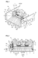
- Fig. 1 is a perspective view showing the internal structure of a thermal transfer printer according to an embodiment of the present invention;
- Fig. 2 is a front elevational view of the thermal transfer printer according to the embodiment shown in Fig. 1:
- Fig. 3 is a front elevational view showing a head portion pressing member and a shaft of the thermal transfer printer according to the embodiment shown in Fig. 1;
- Figs. 4 and 5 are perspective views for illustrating the mounting structures of the head portion pressing member and the shaft of the thermal transfer printer according to the embodiment shown in Fig. 1;
- Figs. 6 and 7 are perspective views showing the structure of a print head of the thermal transfer printer according to the embodiment shown in Fig. 1;
- Fig. 8 is an enlarged detailed diagram of the head portion pressing member of the thermal transfer printer according to the embodiment shown in Fig. 1; and
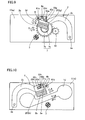
- Figs. 9 to 14 are sectional views for illustrating operations for pressing and separating the print head against and from the platen roller in the thermal transfer printer according to the embodiment shown in Fig. 1.
- An embodiment of the present invention is now described with reference to the drawings.
- First, the structure of a thermal transfer printer according to this embodiment is described with reference to Figs. 1 to 8. The embodiment of the present invention is applied to the thermal transfer printer, an exemplary image generating apparatus.
- As shown in Figs. 1 and 2, the thermal transfer printer according to this embodiment comprises a
metal chassis 1, aprint head 2 for printing, aplaten roller 3, twoplaten roller bearings 4, ametal support rod 5, two headportion pressing members resin drive gear 7, a motor 8 (see Fig. 2), amotor bracket 9 and anintermediate gear 10. Thesupport rod 5 is an example of the "rotary shaft" in the present invention, and thedrive gear 7 is an example of the "gear" in the present invention. - The
chassis 1 has first and second side surfaces 1a and 1b opposed to each other. The first and second side surfaces 1a and 1b of thechassis 1 are provided withsupport holes 1c for rotatably supporting thesupport rod 5 respectively. An inksheet receiving hole 1d is provided on thesecond side surface 1b of thechassis 1, for receiving an ink sheet (not shown). The twoplaten roller bearings 4 are mounted on the first and second side surfaces 1a and 1b of thechassis 1 respectively, for rotatably supporting theplaten roller 3. -
Support portions 5a are provided on both ends of thesupport rod 5 respectively. Thesupport portions 5a of thesupport rod 5 are fitted into the support holes 1c provided on the first and second side surfaces 1a and 1b of thechassis 1 respectively. As shown in Fig. 3, headportion pressing members support rod 5 respectively in an unidling manner. More specifically, D-shapedinsert portions 5b are provided around both ends of thesupport rod 5 respectively, as shown in Figs. 4 and 5. The two headportion pressing members holes insert portions 5b provided around both ends of thesupport rod 5 respectively. Thus, thesupport rod 5 as well as the second headportion pressing member 6b rotate upon rotation of the first headportion pressing member 6a. The headportion pressing members chassis 1 respectively, as shown in Figs. 1 and 2. - According to this embodiment, the first head
portion pressing member 6a is integrally formed with apressing portion 62a and agear portion 63a, as shown in Fig. 4. The second headportion pressing member 6b is integrally formed with apressing portion 62b and aprotrusion 63b protruding from thepressing portion 62b in the extensional direction of thesupport rod 5, as shown in Fig. 5. Theprotrusion 63b is an example of the "first engaging portion" in the present invention. - As shown in Figs. 6 and 7, the
print head 2 has a pair ofsupport shafts 2a, ahead portion 2b opposed to the platen roller 3 (see Figs. 1 and 2) and a pair ofarms 2c coupling thesupport shafts 2a and thehead portion 2b with each other. Thisprint head 2 is rotatable about thesupport shafts 2a. In other words, the pair ofsupport shafts 2a of theprint head 2 are rotatably mounted on the first and second side surfaces 1a and 1b of thechassis 1 respectively. - According to this embodiment, first and second
torsion coil springs head portion 2b toward the platen roller 3 (see Figs. 1 and 2) are arranged on the upper portion of thehead portion 2b in regions corresponding to the first and second headportion pressing members spring fixing member 2f formed by a plate body consisting of first and secondspring fixing portions head portion 2b with ascrew 2i. The first and secondspring fixing portions spring fixing member 2f are arranged in the axial direction of theplaten roller 3 at a prescribed interval. The first and secondspring fixing portions spring fixing section 23g and an upright wall-shapedengaging portion 23h, also serving as a spring fixing section, opposed to each other respectively. The first and secondtorsion coil springs spring fixing portions spring fixing member 2f respectively. The firstspring fixing portion 2g of thespring fixing member 2f is provided with astop portion 21g and aprotrusion 22g, as shown in Figs. 6 and 7. The secondspring fixing portion 2h of thespring fixing member 2f is also provided with astop portion 21h and aprotrusion 22h. The firsttorsion coil spring 2d is an example of the "first spring member" in the present invention, and the secondtorsion coil spring 2e is an example of the "second spring member" in the present invention. - According to this embodiment, the first
torsion coil spring 2d has afirst end 21d pressed by thepressing portion 62a of the first headportion pressing member 6a upon downward rotation of the first headportion pressing member 6a and asecond end 22d transmitting urging force resulting from the pressedfirst end 21d to thehead portion 2b, as shown in Figs. 2, 6 and 7. The secondtorsion coil spring 2e has afirst end 21e pressed by thepressing portion 62b of the second headportion pressing member 6b upon downward rotation of the second headportion pressing member 6b and asecond end 22e transmitting urging force resulting from the pressedfirst end 21e to thehead portion 2b. Thehead portion 2b is pressed against theplaten roller 3 due to the urging force transmitted thereto from thetorsion coil springs first end 21d of the firsttorsion coil spring 2d is stopped on thestop portion 21g of thespring fixing member 2f, while thesecond end 22d thereof is fixed to theprotrusion 22g of thespring fixing member 2f. Thefirst end 21e of the secondtorsion coil spring 2e is stopped on thestop portion 21h of thespring fixing member 2f, while thesecond end 22e thereof is fixed to theprotrusion 22h of thespring fixing member 2f. - According to this embodiment, the engaging
portion 23h having anotch 24h engaging with theprotrusion 63b of the second headportion pressing member 6b is integrally formed on the secondspring fixing portion 2h of thespring fixing member 2f by partially uprighting thespring fixing member 2f, as shown in Fig. 8. Thus, theprotrusion 63b of the second headportion pressing member 6b and thenotch 24h of the secondspring fixing portion 2h engage with each other upon upward rotation of the second headportion pressing member 6b, thereby upwardly rotating thehead portion 2b. Consequently, thehead portion 2b having been pressed against the platen roller 3 (see Figs. 1 and 2) is separated from theplaten roller 3 upon rotation of the second headportion pressing member 6b. Achamfer 25h is formed on the opening side of thenotch 24h, in order to simplify the engagement with theprotrusion 63b. The engagingportion 23h is an example of the "second engaging portion" in the present invention. - According to this embodiment, the
drive gear 7 and theintermediate gear 10 are provided for rotating the headportion pressing members motor 8 thereto, as shown in Figs. 1 and 2. Thedrive gear 7 and theintermediate gear 10 are mounted only on thefirst side surface 1a of thechassis 1. Themotor 8 is mounted on thefirst side surface 1a of thechassis 1 through themotor bracket 9. A smalldiameter gear portion 7a of thedrive gear 7 meshes with thegear portion 63a of the first headportion pressing member 6a, while a largediameter gear portion 7b of thedrive gear 7 meshes with asmall diameter gear 10a of theintermediate gear 10. Alarge diameter gear 10b of theintermediate gear 10 meshes with amotor gear 8a of themotor 8. Thus, driving of themotor 8 is transmitted to the first headportion pressing member 6a through theintermediate gear 10 and thedrive gear 7. - Operations of the thermal transfer printer according to this embodiment for pressing the
print head 2, separated from theplaten roller 3, against theplaten roller 3 are now described with reference to Figs. 2 and 9 to 14. - In an initial state, the
head portion 2b of theprint head 2 is held on a spaced position with respect to theplaten roller 3, as shown in Figs. 9 and 10. At this time, theprotrusion 63b of the second headportion pressing member 6b engages with thenotch 24h of the engagingportion 23h of the secondspring fixing portion 2h provided on the upper portion of thehead portion 2b as shown in Fig. 10, thereby restraining thehead portion 2b from rotation along arrow B in Fig. 10. - When the motor 8 (see Fig. 2) is driven from the initial state shown in Figs. 9 and 10, the driving force of the
motor 8 is transmitted to thegear portion 63a of the first headportion pressing member 6a through theintermediate gear 10 and thedrive gear 7, thereby rotating the first headportion pressing member 6a about thesupport rod 5 along arrow A as shown in Fig. 11. At this time, the first and second headportion pressing members support rod 5, whereby the second headportion pressing member 6b is also rotated along arrow A. Thehead portion 2b, having been restrained from rotating along arrow B by theprotrusion 63b, is also rotated along arrow B due to rotation of theprotrusion 63b of the second headportion pressing member 6b along arrow A. Thus, thehead portion 2b is moved toward the platen roller 3 (press side), as shown in Figs. 13 and 14. The direction of arrow A is an example of the "first direction" in the present invention. - In this state where the
print head 2 is moved toward theplaten roller 3, the headportion pressing members pressing portion 62a of the first headportion pressing member 6a presses thefirst end 21d of the firsttorsion coil spring 2d of theprint head 2. Further, thepressing portion 62b of the second headportion pressing member 6b presses thefirst end 21e of the secondtorsion coil spring 2e of theprint head 2. At this time, urging force is generated in thetorsion coil springs head portion 2b through the second ends 22d and 22e of thetorsion coil springs head portion 2b is urged toward theplaten roller 3. In this state, the engagement between theprotrusion 63b of the second headportion pressing member 6b and thenotch 24h of the engagingportion 23h of thespring fixing member 2f is canceled. - Operations of separating the
print head 2 of the thermal transfer printer according to this embodiment from theplaten roller 3 are now described with reference to Figs. 9 to 14. - As shown in Figs. 13 and 14, the
head portion 2b is in the state urged toward theplaten roller 3. From the state shown in Fig. 13, the motor 8 (see Fig. 2) is so driven that the driving force thereof is transmitted to thegear portion 63a of the first headportion pressing member 6a through theintermediate gear 10 and thedrive gear 7, thereby rotating the first headportion pressing member 6a about thesupport rod 5 along arrow C in Fig. 13. At this time, the first and second headportion pressing members support rod 5, whereby the second headportion pressing member 6b is also rotated along arrow C in Fig. 14. Thus, thehead portion 2b is released from the force urging the same toward theplaten roller 3 through thetorsion coil springs portion pressing members protrusion 63b of the second headportion pressing member 6b engages with thenotch 24h of the engagingportion 23h of the secondspring fixing portion 2h of thespring fixing member 2f mounted on thehead portion 2b. The direction of arrow C is an example of the "second direction" in the present invention. - When the head
portion pressing members print head 2 is also lifted up and rotated along arrow D in Fig. 12 following this rotation of the headportion pressing members protrusion 63b of the second headportion pressing member 6b and thenotch 24h of the engagingportion 23h of thespring fixing member 2f mounted on thehead portion 2b. Thus, thehead portion 2b is separated from theplaten roller 3. The headportion pressing members print head 2 is also rotated along arrow D and moved to the spaced position with respect to theplaten roller 3, as shown in Fig. 10. This spaced position of theprint head 2 corresponds to the initial state of the operation of pressing thehead portion 2b against theplaten roller 3. Thus, theprint head 2 is moved from the position urged toward the platen roller 3 (see Fig. 14) to the spaced position where thehead portion 2b is separated from the platen roller 3 (see Fig. 10). - According to this embodiment, as hereinabove described, the
drive gear 7 is arranged on the first end of thesupport rod 5 for rotating the headportion pressing members support rod 5 by transmitting the driving force of themotor 8 thereto and thegear portion 63a meshing with thedrive gear 7 is formed on the first headportion pressing member 6a so that the driving force of themotor 8 can be transmitted to the headportion pressing members drive gear 7, whereby the upper portion of thehead portion 2b of theprint head 2 can be pressed with the headportion pressing members support rod 5. When the headportion pressing members print head 2, therefore, theprint head 2 can be uniformly pressed against theplaten roller 3 with the headportion pressing members support rod 5 with thegear portion 63a arranged on the first end of thesupport rod 5, whereby the thermal transfer printer can be inhibited from applying nonuniform pressing force against theprint head 2 although thedrive gear 7 is not arranged on each end of thesupport rod 5. Thus, thedrive gear 7 for rotating the headportion pressing members support rod 5, whereby the number of components can be reduced. - According to this embodiment, the second head
portion pressing member 6b is provided with the protrusion protruding in the extensional direction of thesupport rod 5 while the secondspring fixing portion 2h of thespring fixing member 2f mounted on thehead portion 2b of theprint head 2 is provided with thenotch 24h engaging with theprotrusion 63b of the second headportion pressing member 6b upon upward rotation of the second headportion pressing member 6b so that thehead portion 2b of theprint head 2 can be upwardly rotated due to the engagement between thenotch 24h of the secondspring fixing portion 2h of thespring fixing member 2f mounted on thehead portion 2b of theprint head 2 and theprotrusion 63b of the second headportion pressing member 6b upon upward rotation of the second headportion pressing member 6b, whereby thehead portion 2b of theprint head 2 can be separated from theplaten roller 3 through the upward rotation of the second headportion pressing member 6b. Thus, no mechanical portion may be additionally provided for separating thehead portion 2b of theprint head 2 from theplaten roller 3, whereby the number of components can be reduced also according to this structure. - According to this embodiment, the
drive gear 7 for rotating the headportion pressing members support rod 5 may not be arranged on each end of thesupport rod 5 and no mechanical portion may be additionally provided for separating thehead portion 2b of theprint head 2 from theplaten roller 3, whereby the thermal transfer printer can be downsized. - According to this embodiment, the
spring fixing member 2f having the first and secondspring fixing portions platen roller 3 at the prescribed interval is mounted on thehead portion 2b of theprint head 2 while the first and secondtorsion coil springs head portion 2b toward theplaten roller 3 are fixed to the first and secondspring fixing portions spring fixing member 2f respectively for generating urging force in the firsttorsion coil spring 2d by pressing the same with the first headportion pressing member 6a rotated following driving of thedrive gear 7 and generating urging force in the secondtorsion coil spring 2e by pressing the same with the second headportion pressing member 6b corotating with the first headportion pressing member 6a, whereby theprint head 2 can be urged toward theplaten roller 3 with the twotorsion coil springs head portion 2b of theprint head 2 can be stably pressed against theplaten roller 3 as compared with a case of urging thehead portion 2b of theprint head 2 toward theplaten roller 3 with urging force of a single spring member. - According to this embodiment, the
gear portion 63a meshing with thedrive gear 7 is so integrally provided on the first headportion pressing member 6a that the number of components can be inhibited from increase despite thegear portion 63a provided on the first headportion pressing member 6a. - According to this embodiment, the
protrusion 63b protruding in the extensional direction of thesupport rod 5 is integrally provided on the second headportion pressing member 6b while the engagingportion 23h including thenotch 24h engaging with theprotrusion 63b of the second headportion pressing member 6b is integrally provided on the secondspring fixing portion 2h of thespring fixing member 2f, whereby the number of components can be inhibited from increase despite theprotrusion 63b and the engagingportion 23h including thenotch 24h provided on the second headportion pressing member 6b and the secondspring fixing portion 2h of thespring fixing member 2f respectively. - Although the present invention has been described and illustrated in detail, it is clearly understood that the same is by way of illustration and example only and is not to be taken by way of limitation, the spirit and scope of the present invention being limited only by the terms of the appended claims.
- For example, while the aforementioned embodiment of the present invention is applied to the thermal transfer printer, the present invention is not restricted to this but is also applicable to another image generating apparatus other than the thermal transfer printer.
- While the second head portion pressing member is formed with the protrusion and the second spring fixing portion of the spring fixing member provided on the upper portion of the head portion is formed with the engaging portion including the notch engaging with the protrusion in the aforementioned embodiment, the present invention is not restricted to this but the first head portion pressing member may alternatively be formed with a protrusion so that the first spring fixing portion of the spring fixing member provided on the upper portion of the head portion is formed with an engaging portion including a notch engaging with the protrusion.
- While the head portion pressing member is formed with the protrusion and the spring fixing member is provided with the engaging portion including the notch engaging with the protrusion in the aforementioned embodiment, the present invention is not restricted to this but a member other than the head portion pressing member corotating with the head portion pressing member may alternatively be formed with a protrusion so that another member other than the spring fixing member of the head portion is formed with an engaging portion including a notch engaging with this protrusion.
- While the two torsion coil springs are pressed with the two head portion pressing members while the head portion of the print head is urged toward the platen roller with the urging force generated in the two torsion coil springs in the aforementioned embodiment, the present invention is not restricted to this but a single torsion coil spring may alternatively be pressed with a single head portion pressing member for urging the head portion of the print head toward the platen roller with urging force generated in the single torsion coil spring. Further alternatively, at least three torsion coil springs may be pressed with at least three head portion pressing members respectively for urging the head portion of the print head toward the platen roller with urging force generated in at least three torsion coil springs.
- While the gear portion is integrally provided on the first head portion pressing member for rotating the head portion pressing member by transmitting the driving force of the motor to the gear portion in the aforementioned embodiment, the present invention is not restricted to this but a gear portion may alternatively be provided independently of the head portion pressing member for rotating the head portion pressing member by transmitting the driving force of the motor to the independently provided gear portion.
- While the engaging portion including the notch engaging with the protrusion of the second head portion pressing member is integrally formed on the spring fixing member in the aforementioned embodiment, the present invention is not restricted to this but the engaging portion may alternatively be provided on another member including a notch, other than the spring fixing member, constituting the print head. Further alternatively, a single engaging member including a notch may be mounted on the print head.
Claims (17)
- An image generating apparatus comprising:a platen roller (3);a print head (2), opposed to said platen roller (3), having a head portion (2b) pressed against said platen roller (3);a head portion pressing member (6a, 6b) provided independently of said print head (2) and mounted on a rotary shaft for pressing said head portion (2b) of said print head (2) against said platen roller (3); anda gear (7) arranged on a first end of said rotary shaft for rotating said head portion (2b), whereinsaid head portion pressing member (6a, 6b) is provided with a gear portion (63a) meshing with said gear (7) and a first engaging portion (63b), andsaid head portion (2b) is provided with a second engaging portion (23h) engaging with said first engaging portion (63b) of said head portion pressing member (6a, 6b) upon upward rotation of said head portion pressing member (6a, 6b).
- The image generating apparatus according to claim 1, wherein
said print head (2) includes a spring fixing member (2f), mounted on said head portion (2b), having a first spring fixing portion (2g) and a second spring fixing portion (2h) arranged in the axial direction of said platen roller (3) at a prescribed interval as well as a first spring member (2d) and a second spring member (2e) fixed to said first spring fixing portion (2g) and said second spring fixing portion (2h) of said spring fixing member (2f) respectively for urging said head portion (2b) toward said platen roller (3), and
said head portion pressing member (6a, 6b) includes a first head portion pressing member (6a) for generating urging force in said spring member (2d, 2e) by pressing said first spring member (2d) through rotation following driving of said gear (7) and a second head portion pressing member (6b) for generating urging force in said second spring member (2e) by pressing said second spring member (2e) through corotation with said first head portion pressing member (6a). - The image generating apparatus according to claim 1, wherein
said first head portion pressing member (6a) is integrally provided with said gear portion (63a) meshing with said gear (7). - The image generating apparatus according to claim 2, wherein
said first engaging portion (63b) is provided on either said first head portion pressing member (6a) or said second head portion pressing member (6b), and
said second engaging portion (23h) is provided on either said first spring fixing portion (2g) or said second spring fixing portion (2h) corresponding to said first or second head portion pressing member (6a, 6b) provided with said first engaging portion (63b). - The image generating apparatus according to claim 4, wherein
said first engaging portion (63b) includes a protrusion (63b) integrally provided on said second head portion pressing member (6b) to protrude in the extensional direction of said rotary shaft, and
said second engaging portion (23h) includes a notch (24h) integrally provided on said second spring fixing portion (2h) of said spring fixing member (2f) for engaging with said protrusion (63b) of said second head portion pressing member (6b) upon upward rotation of said second head portion pressing member (6b). - The image generating apparatus according to claim 5, wherein
said second spring fixing portion (2h) includes an upright wall (23h) formed by partially uprighting said spring fixing member (2f) formed by a plate body, and
said notch (24h) is formed on said upright wall (23h). - The image generating apparatus according to claim 4, wherein
a chamfer is formed on the opening side of said notch (24h). - The image generating apparatus according to claim 2, wherein
said first head portion pressing member (6a) and said second head portion pressing member (6b) press said first spring member (2d) and said second spring member (2e) respectively while the engagement between said first engaging portion (63b) and said second engaging portion (23h) is canceled. - The image generating apparatus according to claim 2, wherein
said first spring member (2d) and said second spring member (2e) are torsion coil springs. - The image generating apparatus according to claim 1, wherein
said print head (2) further includes a support shaft (2a) and an arm (2c) coupling said support shaft (2a) and said head portion (2b) with each other and is rotatable about said support shaft (2a),
said head portion pressing member (6a, 6b) rotates in a first direction thereby rotating said print head (2) for pressing and moving said head portion (2b) toward said platen roller (3) in printing, and
said head portion pressing member (6a, 6b) rotates in a second direction opposite to said first direction upon engagement between said first engaging portion (63b) and said second engaging portion (23h) thereby rotating said print head (2) for separating said head portion (2b) from said platen roller (3) in nonprinting. - An image generating apparatus comprising:a platen roller (3);a print head (2), opposed to said platen roller (3), having a head portion (2b) pressed against said platen roller (3);a head portion pressing member (6a, 6b) provided independently of said print head (2) and mounted on a rotary shaft for pressing said head portion (2b) of said print head (2) against said platen roller (3); anda gear (7) arranged on a first end of said rotary shaft for rotating said head portion (2b) by transmitting driving force of a motor to said head portion pressing member (6a, 6b), whereinsaid print head (2) further includes a spring fixing member (2f), mounted on said head portion (2b), having a first spring fixing portion (2g) and a second spring fixing portion (2h) arranged in the axial direction of said platen roller (3) at a prescribed interval as well as a first spring member (2d) and a second spring member (2e) fixed to said first spring fixing portion (2g) and said second spring fixing portion (2h) of said spring fixing member (2f) respectively for urging said head portion (2b) toward said platen roller (3),said head portion pressing member (6a, 6b) further includes a first head portion pressing member (6a) for generating urging force in said spring member (2d, 2e) by pressing said first spring member (2d) through rotation following driving of said gear (7) and a second head portion pressing member (6b) for generating urging force in said second spring member (2e) by pressing said second spring member (2e) through corotation with said first head portion pressing member (6a),said first head portion pressing member (6a) is integrally provided with a gear portion (63a) meshing with said gear (7), andsaid second head portion pressing member (6b) is integrally provided with a protrusion (63b) protruding in the extensional direction of said rotary shaft while said second spring fixing portion (2h) of said spring fixing member (2f) is integrally provided with a notch (24h) engaging with said protrusion (63b) of said second head portion pressing member (6b) upon upward rotation of said second head portion pressing member (6b).
- The image generating apparatus according to claim 11, wherein
said first engaging portion (63b) is provided on either said first head portion pressing member (6a) or said second head portion pressing member (6b), and
said second engaging portion (23h) is provided on either said first spring fixing portion (2g) or said second spring fixing portion (2h) corresponding to said first or second head portion pressing member (6a, 6b) provided with said first engaging portion (63b). - The image generating apparatus according to claim 11, wherein
said second spring fixing portion (2h) includes an upright wall (23h) formed by partially uprighting said spring fixing member (2f) formed by a plate body, and
said notch (24h) is formed on said upright wall (23h). - The image generating apparatus according to claim 11, wherein
a chamfer is formed on the opening side of said notch (24h). - The image generating apparatus according to claim 11, wherein
said first head portion pressing member (6a) and said second head portion pressing member (6b) press said first spring member (2d) and said second spring member (2e) respectively while the engagement between said first engaging portion (63b) and said second engaging portion (23h) is canceled. - The image generating apparatus according to claim 11, wherein
said first spring member (2d) and said second spring member (2e) are torsion coil springs. - The image generating apparatus according to claim 11, wherein
said print head (2) further includes a support shaft (2a) and an arm (2c) coupling said support shaft (2a) and said head portion (2b) with each other and is rotatable about said support shaft (2a),
said head portion pressing member (6a, 6b) rotates in a first direction thereby rotating said print head (2) for pressing and moving said head portion (2b) toward said platen roller (3) in printing, and
said head portion pressing member (6a, 6b) rotates in a second direction opposite to said first direction upon engagement between said first engaging portion (63b) and said second engaging portion (23h) thereby rotating said print head (2) for separating said head portion (2b) from said platen roller (3) in nonprinting.
Applications Claiming Priority (1)
| Application Number | Priority Date | Filing Date | Title |
|---|---|---|---|
| JP2005165079A JP4945928B2 (en) | 2005-06-06 | 2005-06-06 | Image forming apparatus |
Publications (3)
| Publication Number | Publication Date |
|---|---|
| EP1731322A2 true EP1731322A2 (en) | 2006-12-13 |
| EP1731322A3 EP1731322A3 (en) | 2008-06-25 |
| EP1731322B1 EP1731322B1 (en) | 2010-06-30 |
Family
ID=36928575
Family Applications (1)
| Application Number | Title | Priority Date | Filing Date |
|---|---|---|---|
| EP06251519A Expired - Fee Related EP1731322B1 (en) | 2005-06-06 | 2006-03-22 | Image generating apparatus |
Country Status (4)
| Country | Link |
|---|---|
| US (1) | US7495685B2 (en) |
| EP (1) | EP1731322B1 (en) |
| JP (1) | JP4945928B2 (en) |
| DE (1) | DE602006015127D1 (en) |
Cited By (1)
| Publication number | Priority date | Publication date | Assignee | Title |
|---|---|---|---|---|
| EP1900539A3 (en) * | 2006-09-15 | 2009-05-13 | Funai Electric Co., Ltd. | Image generating apparatus |
Families Citing this family (3)
| Publication number | Priority date | Publication date | Assignee | Title |
|---|---|---|---|---|
| CN101434151B (en) * | 2007-11-13 | 2010-10-13 | 旭丽电子(广州)有限公司 | Heat sublimation printer |
| JP5167989B2 (en) * | 2008-07-04 | 2013-03-21 | 船井電機株式会社 | Image forming apparatus |
| JP6324062B2 (en) * | 2013-12-26 | 2018-05-16 | サトーホールディングス株式会社 | Printer |
Citations (4)
| Publication number | Priority date | Publication date | Assignee | Title |
|---|---|---|---|---|
| JPH0615852A (en) | 1992-06-30 | 1994-01-25 | Matsushita Electric Ind Co Ltd | Printer |
| JPH06191066A (en) | 1992-12-28 | 1994-07-12 | Sharp Corp | Thermal transfer printer device |
| JPH09188027A (en) | 1996-01-11 | 1997-07-22 | Victor Co Of Japan Ltd | Thermal transfer printer |
| US20050062834A1 (en) | 2003-07-28 | 2005-03-24 | Kunio Sawai | Thermal-transfer printer |
Family Cites Families (7)
| Publication number | Priority date | Publication date | Assignee | Title |
|---|---|---|---|---|
| US4879566A (en) * | 1987-01-13 | 1989-11-07 | Canon Kabushiki Kaisha | Thermal recording apparatus |
| JPH06122246A (en) | 1991-06-18 | 1994-05-06 | Fujitsu Ltd | Thermal printer |
| JP3100225B2 (en) | 1992-05-01 | 2000-10-16 | チノン株式会社 | Printing device |
| JPH05318857A (en) * | 1992-05-26 | 1993-12-03 | Sony Corp | Paper transport device for line type thermal printer |
| JP2004223731A (en) * | 2003-01-20 | 2004-08-12 | Alps Electric Co Ltd | Thermal printer |
| JP4006700B2 (en) * | 2003-07-28 | 2007-11-14 | 船井電機株式会社 | Thermal transfer printer |
| JP3821389B2 (en) * | 2004-04-13 | 2006-09-13 | 船井電機株式会社 | Thermal transfer printer and image forming apparatus |
-
2005
- 2005-06-06 JP JP2005165079A patent/JP4945928B2/en not_active Expired - Fee Related
-
2006
- 2006-03-22 DE DE602006015127T patent/DE602006015127D1/en not_active Expired - Lifetime
- 2006-03-22 EP EP06251519A patent/EP1731322B1/en not_active Expired - Fee Related
- 2006-05-10 US US11/431,027 patent/US7495685B2/en not_active Expired - Fee Related
Patent Citations (4)
| Publication number | Priority date | Publication date | Assignee | Title |
|---|---|---|---|---|
| JPH0615852A (en) | 1992-06-30 | 1994-01-25 | Matsushita Electric Ind Co Ltd | Printer |
| JPH06191066A (en) | 1992-12-28 | 1994-07-12 | Sharp Corp | Thermal transfer printer device |
| JPH09188027A (en) | 1996-01-11 | 1997-07-22 | Victor Co Of Japan Ltd | Thermal transfer printer |
| US20050062834A1 (en) | 2003-07-28 | 2005-03-24 | Kunio Sawai | Thermal-transfer printer |
Cited By (1)
| Publication number | Priority date | Publication date | Assignee | Title |
|---|---|---|---|---|
| EP1900539A3 (en) * | 2006-09-15 | 2009-05-13 | Funai Electric Co., Ltd. | Image generating apparatus |
Also Published As
| Publication number | Publication date |
|---|---|
| JP4945928B2 (en) | 2012-06-06 |
| EP1731322B1 (en) | 2010-06-30 |
| US7495685B2 (en) | 2009-02-24 |
| US20060274143A1 (en) | 2006-12-07 |
| DE602006015127D1 (en) | 2010-08-12 |
| JP2006335021A (en) | 2006-12-14 |
| EP1731322A3 (en) | 2008-06-25 |
Similar Documents
| Publication | Publication Date | Title |
|---|---|---|
| US7246959B2 (en) | Image formation apparatus and sublimation printer | |
| EP1900531B1 (en) | Thermal printer | |
| EP1731322B1 (en) | Image generating apparatus | |
| EP2060399A2 (en) | Head mechanism of thermal printer | |
| JP3821389B2 (en) | Thermal transfer printer and image forming apparatus | |
| US7453482B2 (en) | Image generating apparatus | |
| US7410162B2 (en) | Image forming apparatus | |
| US20080199238A1 (en) | Image Generating Apparatus | |
| US7344324B2 (en) | Image forming apparatus having a member for pressing a print head element against a platen roller | |
| US20070170642A1 (en) | Image generating apparatus | |
| US7073962B2 (en) | Thermal-transfer printer | |
| US20070041767A1 (en) | Image generating apparatus | |
| EP1714789A3 (en) | Image generating apparatus | |
| JP4006704B2 (en) | Image forming apparatus | |
| JP3891439B2 (en) | Thermal transfer printer and image forming apparatus | |
| US20070040322A1 (en) | Image generating apparatus | |
| US20200276837A1 (en) | Photo printer | |
| US6945719B2 (en) | Cam action shaft lock device and method | |
| JP2003154714A (en) | Thermal printer | |
| JP2005313419A (en) | Sublimation type printer | |
| JPH09277647A (en) | Thermal printer | |
| JP2863394B2 (en) | Thermal transfer printer | |
| JP4336571B2 (en) | Thermal head pressure contact mechanism and thermal printer using the same | |
| JP2005329683A (en) | Image formation apparatus | |
| EP1892111A1 (en) | Image generating apparatus |
Legal Events
| Date | Code | Title | Description |
|---|---|---|---|
| PUAI | Public reference made under article 153(3) epc to a published international application that has entered the european phase |
Free format text: ORIGINAL CODE: 0009012 |
|
| AK | Designated contracting states |
Kind code of ref document: A2 Designated state(s): AT BE BG CH CY CZ DE DK EE ES FI FR GB GR HU IE IS IT LI LT LU LV MC NL PL PT RO SE SI SK TR |
|
| AX | Request for extension of the european patent |
Extension state: AL BA HR MK YU |
|
| PUAL | Search report despatched |
Free format text: ORIGINAL CODE: 0009013 |
|
| AK | Designated contracting states |
Kind code of ref document: A3 Designated state(s): AT BE BG CH CY CZ DE DK EE ES FI FR GB GR HU IE IS IT LI LT LU LV MC NL PL PT RO SE SI SK TR |
|
| AX | Request for extension of the european patent |
Extension state: AL BA HR MK YU |
|
| 17P | Request for examination filed |
Effective date: 20081127 |
|
| AKX | Designation fees paid |
Designated state(s): DE GB |
|
| 17Q | First examination report despatched |
Effective date: 20090206 |
|
| GRAP | Despatch of communication of intention to grant a patent |
Free format text: ORIGINAL CODE: EPIDOSNIGR1 |
|
| GRAS | Grant fee paid |
Free format text: ORIGINAL CODE: EPIDOSNIGR3 |
|
| GRAA | (expected) grant |
Free format text: ORIGINAL CODE: 0009210 |
|
| AK | Designated contracting states |
Kind code of ref document: B1 Designated state(s): DE GB |
|
| REG | Reference to a national code |
Ref country code: GB Ref legal event code: FG4D |
|
| REF | Corresponds to: |
Ref document number: 602006015127 Country of ref document: DE Date of ref document: 20100812 Kind code of ref document: P |
|
| PLBE | No opposition filed within time limit |
Free format text: ORIGINAL CODE: 0009261 |
|
| STAA | Information on the status of an ep patent application or granted ep patent |
Free format text: STATUS: NO OPPOSITION FILED WITHIN TIME LIMIT |
|
| 26N | No opposition filed |
Effective date: 20110331 |
|
| REG | Reference to a national code |
Ref country code: DE Ref legal event code: R097 Ref document number: 602006015127 Country of ref document: DE Effective date: 20110330 |
|
| PGFP | Annual fee paid to national office [announced via postgrant information from national office to epo] |
Ref country code: DE Payment date: 20150317 Year of fee payment: 10 |
|
| PGFP | Annual fee paid to national office [announced via postgrant information from national office to epo] |
Ref country code: GB Payment date: 20150318 Year of fee payment: 10 |
|
| REG | Reference to a national code |
Ref country code: DE Ref legal event code: R119 Ref document number: 602006015127 Country of ref document: DE |
|
| GBPC | Gb: european patent ceased through non-payment of renewal fee |
Effective date: 20160322 |
|
| PG25 | Lapsed in a contracting state [announced via postgrant information from national office to epo] |
Ref country code: GB Free format text: LAPSE BECAUSE OF NON-PAYMENT OF DUE FEES Effective date: 20160322 Ref country code: DE Free format text: LAPSE BECAUSE OF NON-PAYMENT OF DUE FEES Effective date: 20161001 |