EP1731048A1 - Monitoring apparatus for a helmet - Google Patents
Monitoring apparatus for a helmet Download PDFInfo
- Publication number
- EP1731048A1 EP1731048A1 EP06076108A EP06076108A EP1731048A1 EP 1731048 A1 EP1731048 A1 EP 1731048A1 EP 06076108 A EP06076108 A EP 06076108A EP 06076108 A EP06076108 A EP 06076108A EP 1731048 A1 EP1731048 A1 EP 1731048A1
- Authority
- EP
- European Patent Office
- Prior art keywords
- helmet
- user
- head
- force
- contact forces
- Prior art date
- Legal status (The legal status is an assumption and is not a legal conclusion. Google has not performed a legal analysis and makes no representation as to the accuracy of the status listed.)
- Ceased
Links
- 238000012544 monitoring process Methods 0.000 title claims description 14
- 238000005259 measurement Methods 0.000 abstract 1
- 238000010586 diagram Methods 0.000 description 7
- 230000000694 effects Effects 0.000 description 3
- 206010019196 Head injury Diseases 0.000 description 1
- 239000011358 absorbing material Substances 0.000 description 1
- 230000001133 acceleration Effects 0.000 description 1
- 238000006243 chemical reaction Methods 0.000 description 1
- 230000001351 cycling effect Effects 0.000 description 1
- 239000004744 fabric Substances 0.000 description 1
- 238000001914 filtration Methods 0.000 description 1
- 239000012530 fluid Substances 0.000 description 1
- 230000007257 malfunction Effects 0.000 description 1
- 238000000034 method Methods 0.000 description 1
- 238000012986 modification Methods 0.000 description 1
- 230000004048 modification Effects 0.000 description 1
- 229920006327 polystyrene foam Polymers 0.000 description 1
- 230000001105 regulatory effect Effects 0.000 description 1
- 230000000452 restraining effect Effects 0.000 description 1
Images


Classifications
-
- A—HUMAN NECESSITIES
- A42—HEADWEAR
- A42B—HATS; HEAD COVERINGS
- A42B3/00—Helmets; Helmet covers ; Other protective head coverings
- A42B3/04—Parts, details or accessories of helmets
- A42B3/0406—Accessories for helmets
- A42B3/0433—Detecting, signalling or lighting devices
Definitions
- the present invention relates to an electronic monitoring apparatus incorporated into a safety helmet for detecting and alerting the user of improper helmet fit.
- Safety helmets are routinely worn for various vehicle-related and sport-related activities. Although the helmet is designed to protect the user from head injury, the user remains at risk if the helmet is not worn properly. For example, the helmet may not fit properly, the restraining strap(s) may be unfastened or improperly tensioned, and so forth.
- the U.S. Patent No. 6,157,298 to Garfinkel et al. addresses some of these concerns with a safety helmet electronic control module that alerts the user with a prerecorded voice message or warning signal if the chin strap is not fastened or is fastened incorrectly, or if the helmet is situated on the user's head in an unsafe manner.
- a safety helmet can fit improperly even when fastened with a chin strap, and the user may not know what constitutes a proper fit. Accordingly, what is needed is a monitoring apparatus for detecting and alerting the user of improper helmet fit.
- the present invention is directed to an improved safety helmet apparatus for monitoring safety-related parameters including helmet fit and alerting the user of any detected improper usage or fit.
- a distributed array of force sensors disposed in the inner lining of the helmet monitor the helmet attachment force, and a microcontroller responsive to the force sensors and other sensor data determines if the helmet fits the user properly.
- force sensors are provided at the front, back, sides and top of the inner lining, and the microcontroller compares the measured forces to preestablished threshold values to evaluate the fit of the helmet.
- the reference numeral 10 generally designates a safety helmet such as a cycling or sports helmet.
- the helmet 10 has a hard outer shell 12 covering a layer 14 of energy absorbing material such as polystyrene foam and a fabric lining 16 that contacts the head of a person wearing the helmet 10.
- An array of thin pressure or force-responsive sensors designated in FIG. 1 as S1, S2, S3, S4 and S5 are mounted between the energy absorbing layer 14 and the liner 16 for measuring contact forces between the inner periphery of helmet 10 and the front, back, sides and top of the user's head.
- the sensors S1-S5 are in the form of variable resistive sensor pads having characteristic electrical resistances that vary with the amount of compressive force applied thereto.
- piezo-resistive or capacitive sensors can be utilized. It is also possible to implement the invention with a multi-chamber fluid-filled bladder and a set of capacitive or pressure-responsive sensors for indicating the force applied to each chamber. Also, it will be understood that the sensors S1-S5 may be different in number and/or placement than shown in FIG. 1.
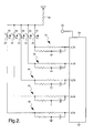
- FIG. 2 is a circuit diagram of a control module mounted in a cavity of the energy absorbing layer 14, for example.
- the module includes a number of small components mounted on a rigid or flexible circuit board, including a battery (not shown), a microcontroller 30, an alarm or indicator 32 that is visible or audible to the user, and a number of passive elements for interfacing the sensors 20-28 with microcontroller 30.
- a regulated voltage VCC is coupled to one terminal of each sensor 20-28 via a current-limiting resistor 34, and a set of interface circuits generally designated by the reference numerals 36, 38, 40, 42 and 44 couple the other terminal of each sensor 20-28 to analog-to-digital input ports AD1-AD5 of microcontroller 30.
- each interface circuit 36-44 includes passive voltage dividing and filtering elements selected to optimize pressure or force sensing range and noise rejection.
- the control module may include additional components such as acceleration-responsive sensors, a low battery indicator and so forth; likewise, the helmet 10 may be equipped with additional sensors for detecting proper use and tensioning of head straps and chin straps, and sensors for detecting the orientation of the helmet 10 on the user's head, for example.
- FIG. 3 depicts an easily implemented processing technique utilized by microcontroller 30 in respect to the sensors 20-28.
- each sensor input Prior to analog-to-digital conversion, each sensor input is an analog voltage that varies over the range of 0-5 VDC in proportion to the respective sensed pressure.
- the microcontroller 30 establishes a pair of calibrated thresholds THRmin and THRmax for each sensor location defining a range of input signal variation (shaded in FIG. 3) for which the contact force between the user's head and the energy absorbing layer 14 is consistent with proper fit of the helmet 10.
- the contact force is too high for a proper fit, indicating that the retaining strap(s) should be loosened or that the helmet 10 is simply too small for the user; and if the sensor input voltage is less than THRmin, the contact force is too low for a proper fit, indicating that the retaining strap(s) should be tightened or that the helmet 10 is simply too large for the user.
- the flow diagram of FIG. 4 represents a software routine that is executed by microcontroller 30 according to this invention.
- the sensors and control module circuitry are powered up at block 70 in response to a user-activated switch or motion sensor.
- the blocks 72, 74 and 76 are then executed before the helmet 10 is placed on the user's head to measure a bias voltage indicative of the sensors' state of health (SOH) and to indicate a sensor malfunction with warning indicator 32 if the measured bias voltage is out of range.
- SOH state of health
- the microcontroller 30 executes the remainder of the routine to compare the sensor readings to the calibrated minimum and maximum thresholds THRmin and THRmax to determine if the helmet fit is proper.
- the blocks 78-84 check for conditions indicative of a helmet that is too small to adequately protect the user.
- the block 78 determines if the inputs for front and rear sensors S1 and S2 exceed THRmax, or if the inputs for the side sensors S3 and S4 exceed THRmax. If either or both conditions are true, the block 80 is periodically executed to determine if the input for the top sensor S5 is also less than THRmin. If block 80 is answered in the affirmative, the helmet 10 is considered to be too small to provide adequate protection to the user, and the blocks 82-84 are executed to provide a warning to that effect via indicator 32.
- the blocks 86-92 check for conditions indicative of a helmet that is too large to adequately protect the user.
- the block 86 determines if the inputs for front and rear sensors S 1 and S2 are less than THRmin, or if the inputs for the side sensors S3 and S4 are less than THRmin. If either or both conditions are true, the block 88 is periodically executed to determine if the input for the top sensor S5 is also greater than THRmin. If block 88 is answered in the affirmative, the helmet 10 is considered to be too large to provide adequate protection to the user, and the blocks 90-92 are executed to provide a warning to that effect via indicator 32.
- the block 94 is executed to determine if the helmet 10 is properly sized for the user. In this case, all of the sensor readings will be within the shaded portion of the diagram of FIG. 3 - that is between THRmin and THRmax. If block 94 determines that this condition is true, the block 96 is executed to provide a suitable indication via indicator 32.
- the present invention provides a simple and convenient way of monitoring for improper fit of a safety helmet, and alerting the user when an improper fit is detected.
- the illustrated apparatus may be used in conjunction with other sensors to provide comprehensive helmet fit and usage monitoring.
- the described functionality of microcontroller 30 may be performed with discrete circuitry, additional indicators or different types of indicators (a dual-color indicator, for example) may be provided, and so on. Accordingly, it is intended that the invention not be limited to the disclosed embodiment, but that it have the full scope permitted by the language of the following claims.
Landscapes
- Helmets And Other Head Coverings (AREA)
Abstract
Description
- The present invention relates to an electronic monitoring apparatus incorporated into a safety helmet for detecting and alerting the user of improper helmet fit.
- Safety helmets are routinely worn for various vehicle-related and sport-related activities. Although the helmet is designed to protect the user from head injury, the user remains at risk if the helmet is not worn properly. For example, the helmet may not fit properly, the restraining strap(s) may be unfastened or improperly tensioned, and so forth. The
U.S. Patent No. 6,157,298 to Garfinkel et al. addresses some of these concerns with a safety helmet electronic control module that alerts the user with a prerecorded voice message or warning signal if the chin strap is not fastened or is fastened incorrectly, or if the helmet is situated on the user's head in an unsafe manner. However, a safety helmet can fit improperly even when fastened with a chin strap, and the user may not know what constitutes a proper fit. Accordingly, what is needed is a monitoring apparatus for detecting and alerting the user of improper helmet fit. - The present invention is directed to an improved safety helmet apparatus for monitoring safety-related parameters including helmet fit and alerting the user of any detected improper usage or fit. A distributed array of force sensors disposed in the inner lining of the helmet monitor the helmet attachment force, and a microcontroller responsive to the force sensors and other sensor data determines if the helmet fits the user properly. In a preferred embodiment, force sensors are provided at the front, back, sides and top of the inner lining, and the microcontroller compares the measured forces to preestablished threshold values to evaluate the fit of the helmet.
-
- FIG. 1 is a bottom inside view of a safety helmet including an array of force sensors according to this invention;
- FIG. 2 is a circuit diagram of the force sensors of FIG. 1 and a microcontroller responsive to the sensors; and
- FIG. 3 is a diagram depicting a logic operation carried out by the microcontroller of FIG. 2 according to this invention;
- FIG. 4 is a flow diagram of a software routine carried out by the microcontroller of FIG. 2 according to this invention.
- Referring to FIG. 1, the
reference numeral 10 generally designates a safety helmet such as a cycling or sports helmet. Thehelmet 10 has a hardouter shell 12 covering alayer 14 of energy absorbing material such as polystyrene foam and afabric lining 16 that contacts the head of a person wearing thehelmet 10. An array of thin pressure or force-responsive sensors designated in FIG. 1 as S1, S2, S3, S4 and S5 are mounted between theenergy absorbing layer 14 and theliner 16 for measuring contact forces between the inner periphery ofhelmet 10 and the front, back, sides and top of the user's head. In the illustrated embodiment, the sensors S1-S5 are in the form of variable resistive sensor pads having characteristic electrical resistances that vary with the amount of compressive force applied thereto. Alternatively, piezo-resistive or capacitive sensors can be utilized. It is also possible to implement the invention with a multi-chamber fluid-filled bladder and a set of capacitive or pressure-responsive sensors for indicating the force applied to each chamber. Also, it will be understood that the sensors S1-S5 may be different in number and/or placement than shown in FIG. 1. - In the circuit diagram of FIG. 2, the sensors S1, S2, S3, S4 and S5 are represented by the
variable resistors energy absorbing layer 14, for example. The module includes a number of small components mounted on a rigid or flexible circuit board, including a battery (not shown), amicrocontroller 30, an alarm orindicator 32 that is visible or audible to the user, and a number of passive elements for interfacing the sensors 20-28 withmicrocontroller 30. A regulated voltage VCC is coupled to one terminal of each sensor 20-28 via a current-limitingresistor 34, and a set of interface circuits generally designated by thereference numerals microcontroller 30. In general, each interface circuit 36-44 includes passive voltage dividing and filtering elements selected to optimize pressure or force sensing range and noise rejection. Of course, the control module may include additional components such as acceleration-responsive sensors, a low battery indicator and so forth; likewise, thehelmet 10 may be equipped with additional sensors for detecting proper use and tensioning of head straps and chin straps, and sensors for detecting the orientation of thehelmet 10 on the user's head, for example. - FIG. 3 depicts an easily implemented processing technique utilized by
microcontroller 30 in respect to the sensors 20-28. Prior to analog-to-digital conversion, each sensor input is an analog voltage that varies over the range of 0-5 VDC in proportion to the respective sensed pressure. Themicrocontroller 30 establishes a pair of calibrated thresholds THRmin and THRmax for each sensor location defining a range of input signal variation (shaded in FIG. 3) for which the contact force between the user's head and theenergy absorbing layer 14 is consistent with proper fit of thehelmet 10. In general, if the sensor input voltage exceeds THRmax, the contact force is too high for a proper fit, indicating that the retaining strap(s) should be loosened or that thehelmet 10 is simply too small for the user; and if the sensor input voltage is less than THRmin, the contact force is too low for a proper fit, indicating that the retaining strap(s) should be tightened or that thehelmet 10 is simply too large for the user. - The flow diagram of FIG. 4 represents a software routine that is executed by
microcontroller 30 according to this invention. The sensors and control module circuitry are powered up atblock 70 in response to a user-activated switch or motion sensor. Theblocks helmet 10 is placed on the user's head to measure a bias voltage indicative of the sensors' state of health (SOH) and to indicate a sensor malfunction withwarning indicator 32 if the measured bias voltage is out of range. If operability of the sensors S1-S5 is confirmed, the user is prompted (byindicator 32, for example) to put on thehelmet 10, and themicrocontroller 30 executes the remainder of the routine to compare the sensor readings to the calibrated minimum and maximum thresholds THRmin and THRmax to determine if the helmet fit is proper. - First, the blocks 78-84 check for conditions indicative of a helmet that is too small to adequately protect the user. When the
helmet 10 is too small, it will be too snug laterally to provide adequate pressure vertically (i.e., to the top of the user's head), even when the chin strap is fastened and properly tensioned. Theblock 78 determines if the inputs for front and rear sensors S1 and S2 exceed THRmax, or if the inputs for the side sensors S3 and S4 exceed THRmax. If either or both conditions are true, theblock 80 is periodically executed to determine if the input for the top sensor S5 is also less than THRmin. Ifblock 80 is answered in the affirmative, thehelmet 10 is considered to be too small to provide adequate protection to the user, and the blocks 82-84 are executed to provide a warning to that effect viaindicator 32. - Second, the blocks 86-92 check for conditions indicative of a helmet that is too large to adequately protect the user. When the
helmet 10 is too large, it will be too loose laterally even when the chin strap is fastened and properly tensioned, and at the same time too snug vertically, assuming that the chin strap is fastened and properly tensioned. Theblock 86 determines if the inputs for front andrear sensors S 1 and S2 are less than THRmin, or if the inputs for the side sensors S3 and S4 are less than THRmin. If either or both conditions are true, theblock 88 is periodically executed to determine if the input for the top sensor S5 is also greater than THRmin. Ifblock 88 is answered in the affirmative, thehelmet 10 is considered to be too large to provide adequate protection to the user, and the blocks 90-92 are executed to provide a warning to that effect viaindicator 32. - If
blocks block 94 is executed to determine if thehelmet 10 is properly sized for the user. In this case, all of the sensor readings will be within the shaded portion of the diagram of FIG. 3 - that is between THRmin and THRmax. Ifblock 94 determines that this condition is true, theblock 96 is executed to provide a suitable indication viaindicator 32. - In summary, the present invention provides a simple and convenient way of monitoring for improper fit of a safety helmet, and alerting the user when an improper fit is detected. As mentioned herein, the illustrated apparatus may be used in conjunction with other sensors to provide comprehensive helmet fit and usage monitoring. It will be recognized that numerous additional modifications and variations will occur to those skilled in the art. For example, the described functionality of
microcontroller 30 may be performed with discrete circuitry, additional indicators or different types of indicators (a dual-color indicator, for example) may be provided, and so on. Accordingly, it is intended that the invention not be limited to the disclosed embodiment, but that it have the full scope permitted by the language of the following claims.
Claims (8)
- Monitoring apparatus for a safety helmet (10), comprising:an array of force-responsive sensors (S1-S5) mounted in the helmet (10) for sensing contact forces between an inner periphery of the helmet (10) and a user's head;a control module (30-44) mounted in the helmet (10) and coupled to the force responsive sensors (S1-S5) for determining if the helmet (10) properly or improperly fits the user's head based on the sensed contact forces; anda warning indicator (32) activated by the control module (30-44) when improper helmet fit is determined.
- The monitoring apparatus of claim 1, wherein said helmet (10) includes an energy absorbing layer (14) covered by an inner lining (16), and said force responsive sensors (S1-S5) are disposed between said energy absorbing layer (14) and said inner lining (16).
- The monitoring apparatus of claim 1, wherein said array of force-responsive sensors (S1-S5) sense contact forces between the inner periphery of the helmet (10) and the sides, front, back and top of the user's head.
- The monitoring apparatus of claim 1, wherein said control module (30-44) compares the sensed contact forces to a pair of calibrated thresholds defining an acceptable range of contact force.
- The monitoring apparatus of claim 4, wherein:said array of force-responsive sensors (S1-S5) sense contact forces between the inner periphery of the helmet (10) and a left side, a right side and a top of the user's head; andsaid control module (30-44) activates said indicator (32) when the contact forces between the helmet (10) and the left and right sides of the user's head are above said acceptable range and the contact force between the helmet (10) and the top of the user's head is below said acceptable range.
- The monitoring apparatus of claim 4, wherein:said array of force-responsive sensors (S1-S5) sense contact forces between the inner periphery of the helmet (10) and a front, a back and a top of the user's head; andsaid control module (30-44) activates said indicator (32) when the contact forces between the helmet (10) and the front and back of the user's head are above said acceptable range and the contact force between the helmet (10) and the top of the user's head is below said acceptable range.
- The monitoring apparatus of claim 4, wherein:said array of force-responsive sensors (S1-S5) sense contact forces between the inner periphery of the helmet (10) and a left side, a right side and a top of the user's head; andsaid control module (30-44) activates said indicator (32) when the contact forces between the helmet (10) and the left and right sides of the user's head are below said acceptable range and the contact force between the helmet (10) and the top of the user's head is above said acceptable range.
- The monitoring apparatus of claim 4, wherein:said array of force-responsive sensors (S1-S5) sense contact forces between the inner periphery of the helmet (10) and a front, a back and a top of the user's head; andsaid control module (30-44) activates said indicator (32) when the contact forces between the helmet (10) and the front and back of the user's head are below said acceptable range and the contact force between the helmet (10) and the top of the user's head is above said acceptable range.
Applications Claiming Priority (1)
| Application Number | Priority Date | Filing Date | Title |
|---|---|---|---|
| US11/147,906 US7570170B2 (en) | 2005-06-08 | 2005-06-08 | Monitoring apparatus for a helmet |
Publications (1)
| Publication Number | Publication Date |
|---|---|
| EP1731048A1 true EP1731048A1 (en) | 2006-12-13 |
Family
ID=36889092
Family Applications (1)
| Application Number | Title | Priority Date | Filing Date |
|---|---|---|---|
| EP06076108A Ceased EP1731048A1 (en) | 2005-06-08 | 2006-05-24 | Monitoring apparatus for a helmet |
Country Status (2)
| Country | Link |
|---|---|
| US (1) | US7570170B2 (en) |
| EP (1) | EP1731048A1 (en) |
Cited By (1)
| Publication number | Priority date | Publication date | Assignee | Title |
|---|---|---|---|---|
| US12326378B2 (en) | 2020-06-25 | 2025-06-10 | Xmetix Ltd. | Injury detection wearable system |
Families Citing this family (31)
| Publication number | Priority date | Publication date | Assignee | Title |
|---|---|---|---|---|
| US20110273286A1 (en) * | 2003-07-14 | 2011-11-10 | Sklar Frederick H | System for Monitoring a Person Wearing Head Gear |
| DE102006027189A1 (en) * | 2006-06-12 | 2007-12-13 | Siemens Ag | Head coil arrangement for magnetic resonance device, has housing with multiple coils arranged in housing with two movable housing parts for adjustment to different enclosed head sizes, where parts are linear and movable against each other |
| US9082277B2 (en) | 2010-02-26 | 2015-07-14 | Thl Holding Company, Llc | Method, system and wireless device for monitoring protective headgear |
| US8588806B2 (en) | 2010-02-26 | 2013-11-19 | Thl Holding Company, Llc | Wireless device and methods for use in a paging network |
| US9041528B2 (en) | 2010-02-26 | 2015-05-26 | Thl Holding Company, Llc | Bridge device for use in a system for monitoring protective headgear |
| US8766798B2 (en) | 2010-02-26 | 2014-07-01 | Thl Holding Company, Llc | Method, system and device for monitoring protective headgear |
| US8981952B2 (en) | 2010-02-26 | 2015-03-17 | Thl Holding Company, Llc | Sensor for use in protective headgear |
| US9078481B2 (en) | 2010-02-26 | 2015-07-14 | Thl Holding Company, Llc | Charging device for use in a system for monitoring protective headgear |
| US8890686B2 (en) | 2010-02-26 | 2014-11-18 | Thl Holding Company, Llc | Monitoring device for use in a system for monitoring protective headgear |
| US8847755B2 (en) | 2010-02-26 | 2014-09-30 | Thl Holding Company, Llc | Handheld communication device for monitoring protective headgear |
| US8896457B2 (en) | 2010-02-26 | 2014-11-25 | Thl Holding Company, Llc | Method, system and wireless device with event detection for monitoring protective headgear |
| US9495847B2 (en) | 2010-02-26 | 2016-11-15 | Thl Holding Company, Llc | Method, system and wireless device for monitoring protective headgear based on power data |
| US9943746B2 (en) | 2010-02-26 | 2018-04-17 | The Holding Company, Llc | Protective headgear with impact diffusion |
| US9711017B2 (en) | 2010-02-26 | 2017-07-18 | Thl Holding Company, Llc | Method, system and wireless device with power management for monitoring protective headgear |
| US8884756B2 (en) | 2010-02-26 | 2014-11-11 | Thl Holding Company, Llc | Monitoring device for use with protective headgear |
| US20120304367A1 (en) * | 2010-02-26 | 2012-12-06 | Thl Holding Company, Llc | Protective helmet |
| US9129499B2 (en) | 2010-02-26 | 2015-09-08 | Thl Holding Company, Llc | Wireless device for monitoring protective headgear |
| US8816852B2 (en) * | 2011-04-06 | 2014-08-26 | Dan L. Dunson | Tamper-proof alarm component and methods of making and using the same |
| US20130289459A1 (en) * | 2012-04-25 | 2013-10-31 | Gene P. Bernardoni | Cranial helmet for infants |
| US10123582B2 (en) | 2013-06-26 | 2018-11-13 | I1 Sensortech, Inc. | Flexible impact sensor for use with a headpiece |
| US10327496B2 (en) | 2014-02-15 | 2019-06-25 | Rex Medical, L.P. | Helmet with varying shock absorption |
| US10413009B2 (en) | 2014-02-15 | 2019-09-17 | Rex Medical, L.P. | Helmet with impact tracking |
| US9013297B1 (en) | 2014-10-17 | 2015-04-21 | Ockham Razor Ventures, LLC | Condition responsive indication assembly and method |
| US9486027B2 (en) | 2014-10-17 | 2016-11-08 | Guardhat, Inc. | Connection assembly for adjoining a peripheral with a host wearable device |
| US10667571B2 (en) | 2014-10-17 | 2020-06-02 | Guardhat, Inc. | Condition responsive indication assembly and method |
| US10383384B2 (en) * | 2014-10-17 | 2019-08-20 | Guardhat, Inc. | Electrical connection for suspension band attachment slot of a hard hat |
| US9642574B2 (en) | 2014-10-17 | 2017-05-09 | Guardhat, Inc. | Biometric sensors assembly for a hard hat |
| US20180082656A1 (en) * | 2015-04-22 | 2018-03-22 | Sony Corporation | Information processing apparatus, information processing method, and program |
| CN106579628A (en) * | 2016-12-31 | 2017-04-26 | 歌尔科技有限公司 | Helmet and method for reducing weight thereof |
| CO2020007401A1 (en) * | 2020-06-17 | 2021-01-29 | Univ Los Andes | Safety system and method for vehicles and vehicle users |
| CN115436952B (en) * | 2022-08-05 | 2024-07-09 | 摩拜(北京)信息技术有限公司 | Helmet wearing state detection method, helmet, and storage medium |
Citations (3)
| Publication number | Priority date | Publication date | Assignee | Title |
|---|---|---|---|---|
| US6003156A (en) * | 1998-05-28 | 1999-12-21 | Anderson; Russell Jeffrey | Safety helmet lockout system |
| US6157298A (en) * | 1999-08-05 | 2000-12-05 | Garfinkel; Mitchell D. | Safety helmet with directional and break signals having AM/FM and two-way communication capability |
| DE19934188A1 (en) * | 1999-07-21 | 2001-02-08 | Martin Nimbach | Safety device for motor cycling helmet comprises transponder in e helmet which sends signal when helmet is correctly fitted which releases lock on starter or another section of motor cycle |
Family Cites Families (3)
| Publication number | Priority date | Publication date | Assignee | Title |
|---|---|---|---|---|
| US3658054A (en) * | 1970-05-11 | 1972-04-25 | Gen Technical Services Inc | Adjustable helmet face mask |
| FR2610178A1 (en) * | 1987-01-29 | 1988-08-05 | Chaise Francois | PROTECTIVE HELMET EQUIPPED WITH A LATCHING SIGNAL |
| US6798392B2 (en) | 2001-10-16 | 2004-09-28 | Hewlett-Packard Development Company, L.P. | Smart helmet |
-
2005
- 2005-06-08 US US11/147,906 patent/US7570170B2/en active Active
-
2006
- 2006-05-24 EP EP06076108A patent/EP1731048A1/en not_active Ceased
Patent Citations (3)
| Publication number | Priority date | Publication date | Assignee | Title |
|---|---|---|---|---|
| US6003156A (en) * | 1998-05-28 | 1999-12-21 | Anderson; Russell Jeffrey | Safety helmet lockout system |
| DE19934188A1 (en) * | 1999-07-21 | 2001-02-08 | Martin Nimbach | Safety device for motor cycling helmet comprises transponder in e helmet which sends signal when helmet is correctly fitted which releases lock on starter or another section of motor cycle |
| US6157298A (en) * | 1999-08-05 | 2000-12-05 | Garfinkel; Mitchell D. | Safety helmet with directional and break signals having AM/FM and two-way communication capability |
Cited By (1)
| Publication number | Priority date | Publication date | Assignee | Title |
|---|---|---|---|---|
| US12326378B2 (en) | 2020-06-25 | 2025-06-10 | Xmetix Ltd. | Injury detection wearable system |
Also Published As
| Publication number | Publication date |
|---|---|
| US7570170B2 (en) | 2009-08-04 |
| US20060293867A1 (en) | 2006-12-28 |
Similar Documents
| Publication | Publication Date | Title |
|---|---|---|
| US7570170B2 (en) | Monitoring apparatus for a helmet | |
| JP6746138B2 (en) | Respiratory protection | |
| US9949516B2 (en) | Interactive helmet system and method | |
| US9126065B2 (en) | Airbag device for the body | |
| US20070056081A1 (en) | Safety helmet | |
| US10251433B2 (en) | Wearable garment | |
| EP2907402B1 (en) | Helmet with impact tracking | |
| US5200736A (en) | Assembly for monitoring helmet thermal conditions | |
| US20140149067A1 (en) | Impact and acceleration detection | |
| EP2191737A1 (en) | Intelligent wearing apparel | |
| EP2774502A1 (en) | Shoe comprising sensors | |
| CN102117533A (en) | Human falling detection protection and alarming device | |
| AU2016253609A1 (en) | A structure to absorb, dissipate and measure a force | |
| EP3527096A1 (en) | Team participant awareness indicator and indicative notification | |
| EP1969573B1 (en) | Personal warning apparatus | |
| US12310432B2 (en) | Wearable protection device | |
| US20250295186A1 (en) | Horse-rider protection system comprising an airbag waistcoat connected to a sensor that senses falling of the horse | |
| KR20180075219A (en) | Helmet system for recognizing dangerous situation | |
| US20220175072A1 (en) | Safety Headwear with Electronic Monitoring | |
| KR20220086199A (en) | Autobicycle shield | |
| GB2583473A (en) | Impact detection arrangement | |
| KR20230094063A (en) | a healthcare smart clothing system that includes the ability to prevent falls for the physically weak | |
| US20220061446A1 (en) | Activation system for wearable airbag | |
| KR100509204B1 (en) | Device for detecting contact pressure of helmet | |
| CN217364766U (en) | Riding protective tool |
Legal Events
| Date | Code | Title | Description |
|---|---|---|---|
| PUAI | Public reference made under article 153(3) epc to a published international application that has entered the european phase |
Free format text: ORIGINAL CODE: 0009012 |
|
| AK | Designated contracting states |
Kind code of ref document: A1 Designated state(s): AT BE BG CH CY CZ DE DK EE ES FI FR GB GR HU IE IS IT LI LT LU LV MC NL PL PT RO SE SI SK TR |
|
| AX | Request for extension of the european patent |
Extension state: AL BA HR MK YU |
|
| 17P | Request for examination filed |
Effective date: 20070613 |
|
| 17Q | First examination report despatched |
Effective date: 20070718 |
|
| AKX | Designation fees paid |
Designated state(s): AT BE BG CH CY CZ DE DK EE ES FI FR GB GR HU IE IS IT LI LT LU LV MC NL PL PT RO SE SI SK TR |
|
| STAA | Information on the status of an ep patent application or granted ep patent |
Free format text: STATUS: THE APPLICATION HAS BEEN REFUSED |
|
| 18R | Application refused |
Effective date: 20090221 |