EP1729547A1 - Apparatus for safely connecting a lamp to the equipment voltage ground - Google Patents
Apparatus for safely connecting a lamp to the equipment voltage ground Download PDFInfo
- Publication number
- EP1729547A1 EP1729547A1 EP06010764A EP06010764A EP1729547A1 EP 1729547 A1 EP1729547 A1 EP 1729547A1 EP 06010764 A EP06010764 A EP 06010764A EP 06010764 A EP06010764 A EP 06010764A EP 1729547 A1 EP1729547 A1 EP 1729547A1
- Authority
- EP
- European Patent Office
- Prior art keywords
- voltage
- lamp
- capacitor
- oscillating
- circuit
- Prior art date
- Legal status (The legal status is an assumption and is not a legal conclusion. Google has not performed a legal analysis and makes no representation as to the accuracy of the status listed.)
- Granted
Links
- 239000003990 capacitor Substances 0.000 claims abstract description 64
- 238000010438 heat treatment Methods 0.000 claims description 24
- 230000001681 protective effect Effects 0.000 claims description 6
- 238000001914 filtration Methods 0.000 claims description 4
- 238000000034 method Methods 0.000 description 3
- 230000000694 effects Effects 0.000 description 2
- 238000001514 detection method Methods 0.000 description 1
- 230000001939 inductive effect Effects 0.000 description 1
- 238000012423 maintenance Methods 0.000 description 1
- 238000012544 monitoring process Methods 0.000 description 1
Images

Classifications
-
- H—ELECTRICITY
- H05—ELECTRIC TECHNIQUES NOT OTHERWISE PROVIDED FOR
- H05B—ELECTRIC HEATING; ELECTRIC LIGHT SOURCES NOT OTHERWISE PROVIDED FOR; CIRCUIT ARRANGEMENTS FOR ELECTRIC LIGHT SOURCES, IN GENERAL
- H05B41/00—Circuit arrangements or apparatus for igniting or operating discharge lamps
- H05B41/14—Circuit arrangements
- H05B41/26—Circuit arrangements in which the lamp is fed by power derived from DC by means of a converter, e.g. by high-voltage DC
- H05B41/28—Circuit arrangements in which the lamp is fed by power derived from DC by means of a converter, e.g. by high-voltage DC using static converters
- H05B41/282—Circuit arrangements in which the lamp is fed by power derived from DC by means of a converter, e.g. by high-voltage DC using static converters with semiconductor devices
- H05B41/285—Arrangements for protecting lamps or circuits against abnormal operating conditions
- H05B41/2851—Arrangements for protecting lamps or circuits against abnormal operating conditions for protecting the circuit against abnormal operating conditions
- H05B41/2855—Arrangements for protecting lamps or circuits against abnormal operating conditions for protecting the circuit against abnormal operating conditions against abnormal lamp operating conditions
-
- H—ELECTRICITY
- H05—ELECTRIC TECHNIQUES NOT OTHERWISE PROVIDED FOR
- H05B—ELECTRIC HEATING; ELECTRIC LIGHT SOURCES NOT OTHERWISE PROVIDED FOR; CIRCUIT ARRANGEMENTS FOR ELECTRIC LIGHT SOURCES, IN GENERAL
- H05B41/00—Circuit arrangements or apparatus for igniting or operating discharge lamps
- H05B41/14—Circuit arrangements
- H05B41/26—Circuit arrangements in which the lamp is fed by power derived from DC by means of a converter, e.g. by high-voltage DC
- H05B41/28—Circuit arrangements in which the lamp is fed by power derived from DC by means of a converter, e.g. by high-voltage DC using static converters
- H05B41/282—Circuit arrangements in which the lamp is fed by power derived from DC by means of a converter, e.g. by high-voltage DC using static converters with semiconductor devices
- H05B41/285—Arrangements for protecting lamps or circuits against abnormal operating conditions
- H05B41/2851—Arrangements for protecting lamps or circuits against abnormal operating conditions for protecting the circuit against abnormal operating conditions
Definitions
- the present invention relates to an apparatus for safely connecting the lamp to the equipment voltage ground (EVG), which comprises a rectification circuit for rectifying the power supply alternating voltage into a direct voltage, and an oscillating circuit for converting said direct voltage into alternating voltage for driving the lamp to work, wherein said oscillating circuit comprises the DC-blocking capacitor, the oscillating inductor and the oscillating capacitor orderly connected in series, and one end of said DC-blocking capacitor is connected to the output rectification voltage of said rectification circuit, and another end thereof is connected to said oscillating inductor, while one end of said oscillating capacitor is connected to the equipment voltage ground, and another end thereof is connected to the working voltage terminal of the lamp.
- EMG equipment voltage ground
- the technical problem to be solved by the present invention is to provide lamp circuit apparatus for safely connecting the lamp to the equipment voltage ground EVG, such that the above-mentioned hidden danger could be removed when the lamp is directly connected to the internal equipment voltage ground EVG.
- the lamp circuit apparatus for safely connecting the lamp to the equipment voltage ground comprises a rectification circuit for rectifying the power supply alternating voltage into a direct voltage, and an oscillating circuit for converting said direct voltage into the alternating voltage for driving the lamp to work, wherein said oscillating circuit comprises the DC-blocking capacitor, the oscillating inductor and the oscillating capacitor orderly connected in series, and one end of said DC-blocking capacitor is connected to the output rectification voltage of said rectification circuit, and another end thereof is connected to said oscillating inductor, while one end of said oscillating capacitor is connected to the equipment voltage ground, and another end thereof is connected to the working voltage terminal of the lamp, and wherein the ground terminal of the lamp is electrically connected to the equipment voltage ground through a parallel circuit formed of a switch and a high impedance capacitor, wherein said switch is controlled by the control circuit provided within said apparatus to be closed only after the lamp is normally ignited, and to keep open under other states.
- the terminal of said oscillating capacitor which is connected to the equipment voltage ground is electrically connected, together with the ground terminal of the lamp, to the equipment voltage ground through said parallel circuit.
- a primary pre-heating coil is connected between said oscillating capacitor and said high impedance capacitor, and that a secondary pre-heating coil is respectively connected to both terminals of the lamp, so that said secondary pre-heating coil pre-heats the filament by using the voltage sensed from the primary pre-heating coil.
- the output voltage of said rectification circuit is connected to the input terminal of said DC-blocking capacitor through the first control switch, then is connected to the equipment voltage ground through the second control switch, such that said oscillating circuit charges by means of the direct voltage through said first control switch and discharges towards the equipment voltage ground through said second control switch.
- said first and second control switch are automatically controlled by said control circuit, so that said oscillating circuit oscillates according to the normal working current of the lamp.
- the output voltage of said rectification circuit is smoothed by means of a downstream-connected filtering capacitor.
- Said DC-blocking capacitor could preferably be 100 times of said oscillating capacitor.
- said rectification circuit is formed of a half-bridge consisting of four diodes.
- the power supply voltage could be connected to said half bridge through a de-interfering capacitor connected in parallel with said power supply voltage so as to filter interference voltage.
- a protective fuse could be connected between said de-interfering capacitor and the power supply.
- the power supply voltage could be connected in parallel to another de-interfering capacitor between said protective fuse and power supply.
- the lamp circuit apparatus as shown in Fig. 3 comprises a rectification circuit formed of a half bridge consisting of four diodes D1-D4, which is used for rectifying the supplied power supply alternating voltage into a direct voltage.
- an oscillator circuit formed of a DC-blocking capacitor C3, an oscillator inductor L1 and an oscillating capacitor C4, which is used for converting said direct voltage into alternating voltage for driving the lamp to work.
- One end of said DC-blocking capacitor C3 is connected to the output rectification voltage of said rectification circuit, and another end thereof is connected to said oscillating inductor L1, while one end of said oscillating capacitor C4 is connected to the equipment voltage ground EVG, and another end thereof is connected to the working voltage terminal of the lamp.
- the ground terminal of the lamp is electrically connected to the equipment voltage ground EVG through a parallel circuit formed of a switch S1 and a high impedance capacitor C5, wherein said switch S1 is controlled by the control circuit (not shown) provided within said apparatus to be closed only after the lamp is normally ignited, and to keep open under other states.
- this embodiment of the present invention differs by adding a parallel circuit formed of a switch S1 and a series circuit including a high impedance capacitor C5 and a primary pre-heating coil Ta.
- the primary pre-heating coil Ta is used in cooperation with the secondary pre-heating coils provided at the two terminals of the lamp, so that the secondary pre-heating coils Tb, Tc pre-heat the filaments by inducing the current from the primary pre-heating coil Ta when the lamp is started.
- the primary pre-heating coil Ta could also be provided, for example, between the oscillating inductor L1 and the oscillating capacitor C4, or between the DC-blocking capacitor C3 and the second switch V3, but it is not limited to the situation shown in Fig. 3, and these designs could also achieve the effect of pre-heating the filament.
- said oscillating capacitor C4 could also be directly electrically connected to the equipment voltage ground EVG.
- the rectified voltage is smoothed by the downstream-connected filtering capacitor C2.
- the output voltage of said rectification circuit is connected to the input terminal of said DC-blocking capacitor C3 through the first control switch V2, then it is connected to the equipment voltage ground EVG through the second control switch V3, such that said oscillating circuit charges by means of the DC voltage through said first control switch and discharges towards the equipment voltage ground EVG through said second control switch V3.
- the DC-blocking capacitor C3 could be 100 times of said oscillating capacitor C4. Said first and second control switch V2 and V3 are automatically controlled by said control circuit, so that said oscillating circuit oscillates according to the normal working current of the lamp.
- the power supply voltage is connected to said half bridge through a de-interfering capacitor C1 connected in parallel with said power supply voltage so as to filter interference voltage.
- a protective fuse F between said de-interfering capacitor C1 and the power supply.
- the power supply voltage is connected in parallel to another de-interfering capacitor C6 between said protective fuse F and power supply.
- the frequency of the oscillating circuit is lowered by the control of said control circuit.
- the voltage across the lamp i.e., the voltage across the two terminals of C4
- the lamp is ignited and the electric current passes the DC-blocking capacitor C3, the oscillating inductor L1 and flows through the lamp connected in parallel to the oscillating capacitor C4 and the primary pre-heating coil Ta.
- the switch S1 which is connected in parallel to the primary pre-heating coil Ta and the high impedance capacitor C5 is controlled by said control circuit at this time to be in a closed state so as to end the pre-heating.
- the lamp circuit apparatus of the present invention functions in the following process:
- Fig. 5 in this regard.
- the ground terminal of the lamp is mistakenly connected to the external ground.
- the lamp circuit apparatus will not be started, and the switch S 1 between the internal equipment voltage ground EVG and the ground terminal of the lamp will be kept open. Therefore, there is no closed loop with strong electric current, accordingly, there will not be damage to the lamp circuit apparatus.
- the high impedance capacitor C5 connected to the switch S1 in parallel has a high impedance on, for example, the mains voltage of 50Hz, so that even if there is said closed loop, the electrical current produced is very weak.
Landscapes
- Circuit Arrangements For Discharge Lamps (AREA)
- Circuit Arrangement For Electric Light Sources In General (AREA)
- Rectifiers (AREA)
Abstract
Description
- The present invention relates to an apparatus for safely connecting the lamp to the equipment voltage ground (EVG), which comprises a rectification circuit for rectifying the power supply alternating voltage into a direct voltage, and an oscillating circuit for converting said direct voltage into alternating voltage for driving the lamp to work, wherein said oscillating circuit comprises the DC-blocking capacitor, the oscillating inductor and the oscillating capacitor orderly connected in series, and one end of said DC-blocking capacitor is connected to the output rectification voltage of said rectification circuit, and another end thereof is connected to said oscillating inductor, while one end of said oscillating capacitor is connected to the equipment voltage ground, and another end thereof is connected to the working voltage terminal of the lamp.
- In the prior art, due to the inconsistency between the equipment voltage ground (EVG) in the lamp circuit apparatus and the actual grounding, there might be dangerous voltage on the lamp or there might be phenomena of damage to the lamp circuit.
- In the case of detecting the end of lamp life, it is very advantageous to directly connect a terminal of the lamp to the equipment voltage ground (EVG), because in this way, the voltage on the lamp to be detected will no longer contain a half value of the DC component of the rectified voltage of the rectification circuit. However, on the other hand, such kind of circuit has a big problem, because when the internal equipment voltage ground (EVG) contacts the external ground terminal, the lamp might be ignited, and this may be one of the following case, i.e., only one terminal of the lamp is connected (e.g., during maintenance) while another terminal thereof is contacted by a person, as shown in Fig. 1. In the known lamp circuit apparatus as shown in Fig. 1, the circuit forms a closed loop via the voltage source, external ground, human body, lamp, internal ground EVG, diode D4 and filtering circuit C1, C6.
- In addition, when the lead of the EVG towards the lamp contacts the external ground, there might be the danger of damaging the lamp circuit apparatus despite if the lamp is connected to the lamp circuit apparatus or not, as shown in Fig. 2.
- For the above reasons, such lamp circuit apparatus in the European market has the above-mentioned danger hiding behind, while in the U. S, such lamp circuit apparatus is not employed due to the high mains voltage.
- The technical problem to be solved by the present invention is to provide lamp circuit apparatus for safely connecting the lamp to the equipment voltage ground EVG, such that the above-mentioned hidden danger could be removed when the lamp is directly connected to the internal equipment voltage ground EVG.
- The lamp circuit apparatus for safely connecting the lamp to the equipment voltage ground according to the present invention comprises a rectification circuit for rectifying the power supply alternating voltage into a direct voltage, and an oscillating circuit for converting said direct voltage into the alternating voltage for driving the lamp to work, wherein said oscillating circuit comprises the DC-blocking capacitor, the oscillating inductor and the oscillating capacitor orderly connected in series, and one end of said DC-blocking capacitor is connected to the output rectification voltage of said rectification circuit, and another end thereof is connected to said oscillating inductor, while one end of said oscillating capacitor is connected to the equipment voltage ground, and another end thereof is connected to the working voltage terminal of the lamp, and wherein the ground terminal of the lamp is electrically connected to the equipment voltage ground through a parallel circuit formed of a switch and a high impedance capacitor, wherein said switch is controlled by the control circuit provided within said apparatus to be closed only after the lamp is normally ignited, and to keep open under other states. By means of this solution, the present invention prevents people from the danger of getting an electric shock and prevents the lamp circuit apparatus from being damaged.
- Preferably, the terminal of said oscillating capacitor which is connected to the equipment voltage ground is electrically connected, together with the ground terminal of the lamp, to the equipment voltage ground through said parallel circuit.
- More preferably, a primary pre-heating coil is connected between said oscillating capacitor and said high impedance capacitor, and that a secondary pre-heating coil is respectively connected to both terminals of the lamp, so that said secondary pre-heating coil pre-heats the filament by using the voltage sensed from the primary pre-heating coil. Thus while achieving the above-mentioned technical effect, the filament is pre-heated.
- According to a further improved solution, the output voltage of said rectification circuit is connected to the input terminal of said DC-blocking capacitor through the first control switch, then is connected to the equipment voltage ground through the second control switch, such that said oscillating circuit charges by means of the direct voltage through said first control switch and discharges towards the equipment voltage ground through said second control switch.
- Preferably, said first and second control switch are automatically controlled by said control circuit, so that said oscillating circuit oscillates according to the normal working current of the lamp.
- Advantageously, the output voltage of said rectification circuit is smoothed by means of a downstream-connected filtering capacitor.
- Said DC-blocking capacitor could preferably be 100 times of said oscillating capacitor.
- Alternatively, said rectification circuit is formed of a half-bridge consisting of four diodes.
- Moreover, the power supply voltage could be connected to said half bridge through a de-interfering capacitor connected in parallel with said power supply voltage so as to filter interference voltage.
- Besides, a protective fuse could be connected between said de-interfering capacitor and the power supply.
- The power supply voltage could be connected in parallel to another de-interfering capacitor between said protective fuse and power supply.
- The embodiments of the present invention will be described in detail hereinafter in connection with the figures, wherein:
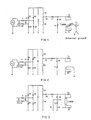
- Fig. 1 shows the situations of danger to people that might appear in the prior art lamp circuit apparatus;
- Fig. 2 shows the situations of damage to the apparatus that might appear in the prior art lamp circuit apparatus;
- Fig. 3 shows an embodiment of the lamp circuit apparatus of the present invention;
- Fig. 4 shows the situation of removing the danger to people in the lamp circuit apparatus of the present invention;
- Fig. 5 shows the situation of removing damage to the apparatus in the lamp circuit apparatus of the present invention;
- The prior art as shown in Fig. 1 and Fig. 2 has been illustrated in the part of background art previously, now reference will be made to the embodiment of the lamp circuit apparatus of the present invention as shown in Fig. 3.
- The lamp circuit apparatus as shown in Fig. 3 comprises a rectification circuit formed of a half bridge consisting of four diodes D1-D4, which is used for rectifying the supplied power supply alternating voltage into a direct voltage. In addition, there is an oscillator circuit formed of a DC-blocking capacitor C3, an oscillator inductor L1 and an oscillating capacitor C4, which is used for converting said direct voltage into alternating voltage for driving the lamp to work. One end of said DC-blocking capacitor C3 is connected to the output rectification voltage of said rectification circuit, and another end thereof is connected to said oscillating inductor L1, while one end of said oscillating capacitor C4 is connected to the equipment voltage ground EVG, and another end thereof is connected to the working voltage terminal of the lamp. The ground terminal of the lamp is electrically connected to the equipment voltage ground EVG through a parallel circuit formed of a switch S1 and a high impedance capacitor C5, wherein said switch S1 is controlled by the control circuit (not shown) provided within said apparatus to be closed only after the lamp is normally ignited, and to keep open under other states.
- By comparing Fig. 3 with the prior art Figs. 1 and 2, it can be seen that this embodiment of the present invention differs by adding a parallel circuit formed of a switch S1 and a series circuit including a high impedance capacitor C5 and a primary pre-heating coil Ta. The primary pre-heating coil Ta is used in cooperation with the secondary pre-heating coils provided at the two terminals of the lamp, so that the secondary pre-heating coils Tb, Tc pre-heat the filaments by inducing the current from the primary pre-heating coil Ta when the lamp is started. Obviously, the primary pre-heating coil Ta could also be provided, for example, between the oscillating inductor L1 and the oscillating capacitor C4, or between the DC-blocking capacitor C3 and the second switch V3, but it is not limited to the situation shown in Fig. 3, and these designs could also achieve the effect of pre-heating the filament.
- In addition, in the embodiment shown in Fig. 3, said oscillating capacitor C4 could also be directly electrically connected to the equipment voltage ground EVG. The rectified voltage is smoothed by the downstream-connected filtering capacitor C2. The output voltage of said rectification circuit is connected to the input terminal of said DC-blocking capacitor C3 through the first control switch V2, then it is connected to the equipment voltage ground EVG through the second control switch V3, such that said oscillating circuit charges by means of the DC voltage through said first control switch and discharges towards the equipment voltage ground EVG through said second control switch V3. The DC-blocking capacitor C3 could be 100 times of said oscillating capacitor C4. Said first and second control switch V2 and V3 are automatically controlled by said control circuit, so that said oscillating circuit oscillates according to the normal working current of the lamp.
- It can be seen from the figure that the power supply voltage is connected to said half bridge through a de-interfering capacitor C1 connected in parallel with said power supply voltage so as to filter interference voltage. There is a protective fuse F between said de-interfering capacitor C1 and the power supply. The power supply voltage is connected in parallel to another de-interfering capacitor C6 between said protective fuse F and power supply.
- The working principle and process of said lamp circuit apparatus will be illustrated in the following.
- During the pre-heating process of the apparatus as shown in Fig. 3, electric current flows through a resonance loop consisting of the DC-blocking capacitor C3, the oscillating inductor L1, the oscillating capacitor C4, the primary pre-heating coil Ta and the high impedance capacitor C5, thereby to sense electric current in the secondary pre-heating coils Ta, Tc to supply to the filament for pre-heating. In this while, the
switch S 1 is controlled to be in the state of open by the present control circuit (not shown) already in said lamp circuit apparatus. - After the pre-heating process, the frequency of the oscillating circuit is lowered by the control of said control circuit. Thus, according to resonance, the voltage across the lamp (i.e., the voltage across the two terminals of C4) reaches a voltage value that is high enough to ignite the lamp. Therefore, the lamp is ignited and the electric current passes the DC-blocking capacitor C3, the oscillating inductor L1 and flows through the lamp connected in parallel to the oscillating capacitor C4 and the primary pre-heating coil Ta.
- After ignition, the switch S1 which is connected in parallel to the primary pre-heating coil Ta and the high impedance capacitor C5 is controlled by said control circuit at this time to be in a closed state so as to end the pre-heating.
- With respect to the possible cases of failures, the lamp circuit apparatus of the present invention functions in the following process:
- 1) In the case that one terminal of the lamp is connected to the lamp circuit apparatus.
Reference could be made to Fig. 4 in this regard. The filament is connected to the cold end of the lamp circuit apparatus (i.e., it is connected to the terminal of the equipment voltage ground EVG). The lamp circuit apparatus starts to operate, that is, it only starts to work when it is detected that filament is electrically connected to the cold end of said lamp circuit apparatus. Said detection could be done by said control circuit. Then the whole pre-heating and ignition process is performed. However, due to a failure in ignition (because another terminal of the lamp is not electrically connected to said lamp circuit apparatus, and this could also be detected by said circuit control apparatus), the whole half bridge circuit is disconnected by the switch V2, while the switch S1 had not been previously activated, i.e., it had not been closed. Therefore, the ground terminal of the lamp is disconnected with the equipment voltage ground EVG through the high impedance capacitor C5. Said high impedance capacitor C5 has high impedance on, for example, the mains voltage of 50Hz, so that there will not be dangerous voltage on the ground terminal of the lamp. - 2) In the case that the lamp is not electrically connected to the lamp circuit apparatus.
- Reference could be made to Fig. 5 in this regard. Suppose that the ground terminal of the lamp is mistakenly connected to the external ground. Through monitoring the filament by, for example, the present control circuit, the lamp circuit apparatus will not be started, and the
switch S 1 between the internal equipment voltage ground EVG and the ground terminal of the lamp will be kept open. Therefore, there is no closed loop with strong electric current, accordingly, there will not be damage to the lamp circuit apparatus. At this time, the high impedance capacitor C5 connected to the switch S1 in parallel has a high impedance on, for example, the mains voltage of 50Hz, so that even if there is said closed loop, the electrical current produced is very weak.
Claims (11)
- A lamp circuit apparatus for safely connecting the lamp to the equipment voltage ground (EVG), comprising a rectification circuit (D1-D4) for rectifying the supplied power supply alternating voltage into a direct voltage, and an oscillating circuit (C3, L1, C4) for converting said direct voltage into alternating voltage for driving the lamp to work, wherein said oscillating circuit comprises the DC-blocking capacitor (C3), the oscillating inductor (L1) and the oscillating capacitor (C4) orderly connected in series, one end of said DC-blocking capacitor (C3) is connected to the output rectification voltage of said rectification circuit, and another end thereof is connected to said oscillating inductor (L1), while one end of said oscillating capacitor (C4) is connected to the equipment voltage ground (EVG), and another end thereof is connected to the working voltage terminal of the lamp,
characterized in that
the ground terminal of the lamp is electrically connected to the equipment voltage ground (EVG) through a parallel circuit formed of a switch (S1) and a high impedance capacitor (C5), wherein said switch (S1) is controlled by the control circuit provided within said apparatus to be closed only after the lamp is normally ignited, and to keep open under other states. - The apparatus according to claim 1, characterized in that the terminal of said oscillating capacitor (C4) which is connected to the equipment voltage ground (EVG) is electrically connected, together with the ground terminal of the lamp, to the equipment voltage ground (EVG) through said parallel circuit.
- The apparatus according to claim 2, characterized in that a primary pre-heating coil (Ta) is connected between said oscillating capacitor (C4) and said high impedance capacitor (C5), and that two secondary pre-heating coils (Tb, Tc) are respectively connected to both terminals of the lamp, so that said secondary pre-heating coils (Tb, Tc) pre-heat the filament by using the voltage sensed from the primary pre-heating coil (Ta).
- The apparatus according to claim 3, characterized in that the output voltage of said rectification circuit is connected to the input terminal of said DC-blocking capacitor (C3) through the first control switch (V2), then is connected to the equipment voltage ground (EVG) through the second control switch (V3), such that said oscillating circuit (C3, L1, C4) charges during work by means of the DC voltage through said first control switch (V2) and discharges towards the equipment voltage ground (EVG) through said second control switch (V3).
- The apparatus according to claim 4, characterized in that said first and second control switch (V2, V3) are automatically controlled by said control circuit, so that said oscillating circuit oscillates according to the normal working current of the lamp.
- The apparatus according to claim 5, characterized in that the output voltage of said rectification circuit (D1-D4) is smoothed by means of a downstream-connected filtering capacitor (C2).
- The apparatus according to any one of claims 1-6, characterized in that said DC-blocking capacitor (C3) is 100 times of said oscillating capacitor (C4).
- The apparatus according to any one of claims 1-6, characterized in that said rectification circuit (D1-D4) is formed of a half-bridge consisting of four diodes (D1-D4).
- The apparatus according to claim 8, characterized in that the power supply voltage is connected to said half bridge through a de-interfering capacitor (C1) connected in parallel with said power supply voltage so as to filter interference voltage.
- The apparatus according to claim 9, characterized in that a protective fuse (F) is connected between said de-interfering capacitor (C1) and the power supply.
- The apparatus according to claim 10, characterized in that the power supply voltage is connected in parallel to another de-interfering capacitor (C6) between said protective fuse (F) and power supply.
Applications Claiming Priority (1)
| Application Number | Priority Date | Filing Date | Title |
|---|---|---|---|
| CN200510074100XA CN1874645B (en) | 2005-05-31 | 2005-05-31 | Device for safely connecting lamp to equipment site |
Publications (2)
| Publication Number | Publication Date |
|---|---|
| EP1729547A1 true EP1729547A1 (en) | 2006-12-06 |
| EP1729547B1 EP1729547B1 (en) | 2008-07-30 |
Family
ID=36950116
Family Applications (1)
| Application Number | Title | Priority Date | Filing Date |
|---|---|---|---|
| EP06010764A Expired - Lifetime EP1729547B1 (en) | 2005-05-31 | 2006-05-24 | Apparatus for safely connecting a lamp to the equipment voltage ground |
Country Status (5)
| Country | Link |
|---|---|
| US (1) | US7439680B2 (en) |
| EP (1) | EP1729547B1 (en) |
| CN (1) | CN1874645B (en) |
| AT (1) | ATE403368T1 (en) |
| DE (1) | DE602006001985D1 (en) |
Families Citing this family (1)
| Publication number | Priority date | Publication date | Assignee | Title |
|---|---|---|---|---|
| DE102009020849A1 (en) | 2009-05-12 | 2010-11-18 | Osram Gesellschaft mit beschränkter Haftung | Circuit arrangement for operating a low-pressure gas discharge lamp and corresponding method |
Citations (3)
| Publication number | Priority date | Publication date | Assignee | Title |
|---|---|---|---|---|
| US4398126A (en) * | 1981-03-30 | 1983-08-09 | Patent-Truehand-Gesellschaft Fur Elektrische Gluhlampen Gmbh | Protected low-pressure discharge lamp operating circuit |
| US4943886A (en) * | 1989-02-10 | 1990-07-24 | Etta Industries, Inc. | Circuitry for limiting current between power inverter output terminals and ground |
| US20020047604A1 (en) * | 2000-09-18 | 2002-04-25 | Patent-Treuhand-Gesellschaft Fuer Elektrische Gluehlampen Mbh | Electronic circuits for detecting filament breakage in gas discharge lamps |
Family Cites Families (7)
| Publication number | Priority date | Publication date | Assignee | Title |
|---|---|---|---|---|
| US5444333A (en) * | 1993-05-26 | 1995-08-22 | Lights Of America, Inc. | Electronic ballast circuit for a fluorescent light |
| US5869935A (en) * | 1997-05-07 | 1999-02-09 | Motorola Inc. | Electronic ballast with inverter protection circuit |
| US5869937A (en) * | 1997-12-17 | 1999-02-09 | Motorola Inc. | High efficiency electronic ballast |
| US6291944B1 (en) * | 2000-05-05 | 2001-09-18 | Universal Lighting Technologies, Inc. | System and method for limiting through-lamp ground fault currents in non-isolated electronic ballasts |
| AU2001280708A1 (en) * | 2000-07-21 | 2002-02-05 | Osram Sylvania Inc. | Method and apparatus for arc detection and protection for electronic ballasts |
| DE10126011A1 (en) * | 2001-05-28 | 2002-12-05 | Patent Treuhand Ges Fuer Elektrische Gluehlampen Mbh | Procedure for starting a discharge lamp |
| US6936973B2 (en) * | 2002-05-31 | 2005-08-30 | Jorge M. Parra, Sr. | Self-oscillating constant-current gas discharge device lamp driver and method |
-
2005
- 2005-05-31 CN CN200510074100XA patent/CN1874645B/en not_active Expired - Fee Related
-
2006
- 2006-05-24 AT AT06010764T patent/ATE403368T1/en active
- 2006-05-24 DE DE602006001985T patent/DE602006001985D1/en not_active Expired - Lifetime
- 2006-05-24 EP EP06010764A patent/EP1729547B1/en not_active Expired - Lifetime
- 2006-05-26 US US11/441,006 patent/US7439680B2/en not_active Expired - Fee Related
Patent Citations (3)
| Publication number | Priority date | Publication date | Assignee | Title |
|---|---|---|---|---|
| US4398126A (en) * | 1981-03-30 | 1983-08-09 | Patent-Truehand-Gesellschaft Fur Elektrische Gluhlampen Gmbh | Protected low-pressure discharge lamp operating circuit |
| US4943886A (en) * | 1989-02-10 | 1990-07-24 | Etta Industries, Inc. | Circuitry for limiting current between power inverter output terminals and ground |
| US20020047604A1 (en) * | 2000-09-18 | 2002-04-25 | Patent-Treuhand-Gesellschaft Fuer Elektrische Gluehlampen Mbh | Electronic circuits for detecting filament breakage in gas discharge lamps |
Also Published As
| Publication number | Publication date |
|---|---|
| EP1729547B1 (en) | 2008-07-30 |
| US7439680B2 (en) | 2008-10-21 |
| ATE403368T1 (en) | 2008-08-15 |
| US20060267519A1 (en) | 2006-11-30 |
| CN1874645A (en) | 2006-12-06 |
| CN1874645B (en) | 2010-09-29 |
| DE602006001985D1 (en) | 2008-09-11 |
Similar Documents
| Publication | Publication Date | Title |
|---|---|---|
| EP0838129B1 (en) | Electronic ballast | |
| EP0838130B1 (en) | Power supply for feeding and igniting a gas discharge lamp | |
| CN101529993B (en) | Ballast with arc protection circuit | |
| US4667131A (en) | Protection circuit for fluorescent lamp ballasts | |
| US5004955A (en) | Electronic ballast with shock protection feature | |
| US5495149A (en) | Power supply | |
| EP1696712A1 (en) | Ballast with arc protection circuit | |
| CN101518157B (en) | Ballast with frequency-diagnostic lamp fault protective circuit | |
| US6809483B2 (en) | Method and apparatus for arc detection and protection for electronic ballasts | |
| US6366032B1 (en) | Fluorescent lamp ballast with integrated circuit | |
| MXPA04002357A (en) | Electronic ballast having end of lamp life, overheating, and shut down protections, and reignition and multiple striking capabilities. | |
| US6291944B1 (en) | System and method for limiting through-lamp ground fault currents in non-isolated electronic ballasts | |
| US6819063B2 (en) | Sensing voltage for fluorescent lamp protection | |
| CA2146772A1 (en) | Ballast circuit equipped with ground fault detector | |
| US20030057866A1 (en) | Electronic ballast and lighting fixture | |
| FI66271B (en) | KRETS FOER GASURLADDNINGSLAMPOR | |
| EP1729547B1 (en) | Apparatus for safely connecting a lamp to the equipment voltage ground | |
| US7432660B2 (en) | IC-based low cost reliable electronic ballast with multiple striking attempts and end of lamp life protection | |
| US6194842B1 (en) | Supply circuit for discharge lamps with overvoltage protection | |
| US7459862B2 (en) | High efficiency electronic ballast for metal halide lamp | |
| EP0198632A2 (en) | Electronic ballast for fluorescent lamps | |
| CA2548839A1 (en) | Apparatus for safely connecting the lamp to the equipment voltage ground | |
| US6552500B1 (en) | Electric lights | |
| US6555970B2 (en) | Ballast for gas discharge lamps with shutdown of the filament heating | |
| EP0948876A2 (en) | Circuit arrangement |
Legal Events
| Date | Code | Title | Description |
|---|---|---|---|
| PUAI | Public reference made under article 153(3) epc to a published international application that has entered the european phase |
Free format text: ORIGINAL CODE: 0009012 |
|
| AK | Designated contracting states |
Kind code of ref document: A1 Designated state(s): AT BE BG CH CY CZ DE DK EE ES FI FR GB GR HU IE IS IT LI LT LU LV MC NL PL PT RO SE SI SK TR |
|
| AX | Request for extension of the european patent |
Extension state: AL BA HR MK YU |
|
| 17P | Request for examination filed |
Effective date: 20070108 |
|
| 17Q | First examination report despatched |
Effective date: 20070212 |
|
| 17Q | First examination report despatched |
Effective date: 20070212 |
|
| AKX | Designation fees paid |
Designated state(s): AT BE BG CH CY CZ DE DK EE ES FI FR GB GR HU IE IS IT LI LT LU LV MC NL PL PT RO SE SI SK TR |
|
| GRAP | Despatch of communication of intention to grant a patent |
Free format text: ORIGINAL CODE: EPIDOSNIGR1 |
|
| GRAS | Grant fee paid |
Free format text: ORIGINAL CODE: EPIDOSNIGR3 |
|
| GRAA | (expected) grant |
Free format text: ORIGINAL CODE: 0009210 |
|
| AK | Designated contracting states |
Kind code of ref document: B1 Designated state(s): AT BE BG CH CY CZ DE DK EE ES FI FR GB GR HU IE IS IT LI LT LU LV MC NL PL PT RO SE SI SK TR |
|
| REG | Reference to a national code |
Ref country code: GB Ref legal event code: FG4D |
|
| REG | Reference to a national code |
Ref country code: CH Ref legal event code: EP |
|
| REF | Corresponds to: |
Ref document number: 602006001985 Country of ref document: DE Date of ref document: 20080911 Kind code of ref document: P |
|
| REG | Reference to a national code |
Ref country code: IE Ref legal event code: FG4D |
|
| REG | Reference to a national code |
Ref country code: SE Ref legal event code: TRGR |
|
| REG | Reference to a national code |
Ref country code: HU Ref legal event code: AG4A Ref document number: E004023 Country of ref document: HU |
|
| PG25 | Lapsed in a contracting state [announced via postgrant information from national office to epo] |
Ref country code: IS Free format text: LAPSE BECAUSE OF FAILURE TO SUBMIT A TRANSLATION OF THE DESCRIPTION OR TO PAY THE FEE WITHIN THE PRESCRIBED TIME-LIMIT Effective date: 20081130 Ref country code: LT Free format text: LAPSE BECAUSE OF FAILURE TO SUBMIT A TRANSLATION OF THE DESCRIPTION OR TO PAY THE FEE WITHIN THE PRESCRIBED TIME-LIMIT Effective date: 20080730 |
|
| PG25 | Lapsed in a contracting state [announced via postgrant information from national office to epo] |
Ref country code: ES Free format text: LAPSE BECAUSE OF FAILURE TO SUBMIT A TRANSLATION OF THE DESCRIPTION OR TO PAY THE FEE WITHIN THE PRESCRIBED TIME-LIMIT Effective date: 20081110 Ref country code: BG Free format text: LAPSE BECAUSE OF FAILURE TO SUBMIT A TRANSLATION OF THE DESCRIPTION OR TO PAY THE FEE WITHIN THE PRESCRIBED TIME-LIMIT Effective date: 20081030 Ref country code: SI Free format text: LAPSE BECAUSE OF FAILURE TO SUBMIT A TRANSLATION OF THE DESCRIPTION OR TO PAY THE FEE WITHIN THE PRESCRIBED TIME-LIMIT Effective date: 20080730 Ref country code: PT Free format text: LAPSE BECAUSE OF FAILURE TO SUBMIT A TRANSLATION OF THE DESCRIPTION OR TO PAY THE FEE WITHIN THE PRESCRIBED TIME-LIMIT Effective date: 20081230 Ref country code: FI Free format text: LAPSE BECAUSE OF FAILURE TO SUBMIT A TRANSLATION OF THE DESCRIPTION OR TO PAY THE FEE WITHIN THE PRESCRIBED TIME-LIMIT Effective date: 20080730 Ref country code: LV Free format text: LAPSE BECAUSE OF FAILURE TO SUBMIT A TRANSLATION OF THE DESCRIPTION OR TO PAY THE FEE WITHIN THE PRESCRIBED TIME-LIMIT Effective date: 20080730 |
|
| PG25 | Lapsed in a contracting state [announced via postgrant information from national office to epo] |
Ref country code: BE Free format text: LAPSE BECAUSE OF FAILURE TO SUBMIT A TRANSLATION OF THE DESCRIPTION OR TO PAY THE FEE WITHIN THE PRESCRIBED TIME-LIMIT Effective date: 20080730 |
|
| PG25 | Lapsed in a contracting state [announced via postgrant information from national office to epo] |
Ref country code: EE Free format text: LAPSE BECAUSE OF FAILURE TO SUBMIT A TRANSLATION OF THE DESCRIPTION OR TO PAY THE FEE WITHIN THE PRESCRIBED TIME-LIMIT Effective date: 20080730 Ref country code: DK Free format text: LAPSE BECAUSE OF FAILURE TO SUBMIT A TRANSLATION OF THE DESCRIPTION OR TO PAY THE FEE WITHIN THE PRESCRIBED TIME-LIMIT Effective date: 20080730 |
|
| PG25 | Lapsed in a contracting state [announced via postgrant information from national office to epo] |
Ref country code: RO Free format text: LAPSE BECAUSE OF FAILURE TO SUBMIT A TRANSLATION OF THE DESCRIPTION OR TO PAY THE FEE WITHIN THE PRESCRIBED TIME-LIMIT Effective date: 20080730 Ref country code: SK Free format text: LAPSE BECAUSE OF FAILURE TO SUBMIT A TRANSLATION OF THE DESCRIPTION OR TO PAY THE FEE WITHIN THE PRESCRIBED TIME-LIMIT Effective date: 20080730 Ref country code: CZ Free format text: LAPSE BECAUSE OF FAILURE TO SUBMIT A TRANSLATION OF THE DESCRIPTION OR TO PAY THE FEE WITHIN THE PRESCRIBED TIME-LIMIT Effective date: 20080730 |
|
| PLBE | No opposition filed within time limit |
Free format text: ORIGINAL CODE: 0009261 |
|
| STAA | Information on the status of an ep patent application or granted ep patent |
Free format text: STATUS: NO OPPOSITION FILED WITHIN TIME LIMIT |
|
| 26N | No opposition filed |
Effective date: 20090506 |
|
| PG25 | Lapsed in a contracting state [announced via postgrant information from national office to epo] |
Ref country code: MC Free format text: LAPSE BECAUSE OF NON-PAYMENT OF DUE FEES Effective date: 20090531 |
|
| REG | Reference to a national code |
Ref country code: IE Ref legal event code: MM4A |
|
| PG25 | Lapsed in a contracting state [announced via postgrant information from national office to epo] |
Ref country code: IE Free format text: LAPSE BECAUSE OF NON-PAYMENT OF DUE FEES Effective date: 20090524 |
|
| PG25 | Lapsed in a contracting state [announced via postgrant information from national office to epo] |
Ref country code: PL Free format text: LAPSE BECAUSE OF FAILURE TO SUBMIT A TRANSLATION OF THE DESCRIPTION OR TO PAY THE FEE WITHIN THE PRESCRIBED TIME-LIMIT Effective date: 20080730 |
|
| PG25 | Lapsed in a contracting state [announced via postgrant information from national office to epo] |
Ref country code: GR Free format text: LAPSE BECAUSE OF FAILURE TO SUBMIT A TRANSLATION OF THE DESCRIPTION OR TO PAY THE FEE WITHIN THE PRESCRIBED TIME-LIMIT Effective date: 20081031 |
|
| REG | Reference to a national code |
Ref country code: CH Ref legal event code: PL |
|
| PG25 | Lapsed in a contracting state [announced via postgrant information from national office to epo] |
Ref country code: LI Free format text: LAPSE BECAUSE OF NON-PAYMENT OF DUE FEES Effective date: 20100531 Ref country code: CH Free format text: LAPSE BECAUSE OF NON-PAYMENT OF DUE FEES Effective date: 20100531 |
|
| PG25 | Lapsed in a contracting state [announced via postgrant information from national office to epo] |
Ref country code: LU Free format text: LAPSE BECAUSE OF NON-PAYMENT OF DUE FEES Effective date: 20090524 |
|
| PGFP | Annual fee paid to national office [announced via postgrant information from national office to epo] |
Ref country code: SE Payment date: 20110510 Year of fee payment: 6 |
|
| PG25 | Lapsed in a contracting state [announced via postgrant information from national office to epo] |
Ref country code: TR Free format text: LAPSE BECAUSE OF FAILURE TO SUBMIT A TRANSLATION OF THE DESCRIPTION OR TO PAY THE FEE WITHIN THE PRESCRIBED TIME-LIMIT Effective date: 20080730 |
|
| PGFP | Annual fee paid to national office [announced via postgrant information from national office to epo] |
Ref country code: NL Payment date: 20110517 Year of fee payment: 6 Ref country code: AT Payment date: 20110408 Year of fee payment: 6 |
|
| PG25 | Lapsed in a contracting state [announced via postgrant information from national office to epo] |
Ref country code: CY Free format text: LAPSE BECAUSE OF FAILURE TO SUBMIT A TRANSLATION OF THE DESCRIPTION OR TO PAY THE FEE WITHIN THE PRESCRIBED TIME-LIMIT Effective date: 20080730 |
|
| PGFP | Annual fee paid to national office [announced via postgrant information from national office to epo] |
Ref country code: IT Payment date: 20110526 Year of fee payment: 6 |
|
| PGFP | Annual fee paid to national office [announced via postgrant information from national office to epo] |
Ref country code: HU Payment date: 20110715 Year of fee payment: 6 |
|
| REG | Reference to a national code |
Ref country code: DE Ref legal event code: R081 Ref document number: 602006001985 Country of ref document: DE Owner name: OSRAM GMBH, DE Free format text: FORMER OWNER: OSRAM GESELLSCHAFT MIT BESCHRAENKTER HAFTUNG, 81543 MUENCHEN, DE Effective date: 20111214 |
|
| REG | Reference to a national code |
Ref country code: DE Ref legal event code: R084 Ref document number: 602006001985 Country of ref document: DE Effective date: 20120417 |
|
| REG | Reference to a national code |
Ref country code: NL Ref legal event code: V1 Effective date: 20121201 |
|
| REG | Reference to a national code |
Ref country code: SE Ref legal event code: EUG |
|
| REG | Reference to a national code |
Ref country code: AT Ref legal event code: MM01 Ref document number: 403368 Country of ref document: AT Kind code of ref document: T Effective date: 20120524 |
|
| PG25 | Lapsed in a contracting state [announced via postgrant information from national office to epo] |
Ref country code: HU Free format text: LAPSE BECAUSE OF NON-PAYMENT OF DUE FEES Effective date: 20120525 Ref country code: AT Free format text: LAPSE BECAUSE OF NON-PAYMENT OF DUE FEES Effective date: 20120524 |
|
| PG25 | Lapsed in a contracting state [announced via postgrant information from national office to epo] |
Ref country code: IT Free format text: LAPSE BECAUSE OF NON-PAYMENT OF DUE FEES Effective date: 20120524 Ref country code: SE Free format text: LAPSE BECAUSE OF NON-PAYMENT OF DUE FEES Effective date: 20120525 |
|
| REG | Reference to a national code |
Ref country code: DE Ref legal event code: R081 Ref document number: 602006001985 Country of ref document: DE Owner name: OSRAM GMBH, DE Free format text: FORMER OWNER: OSRAM AG, 81543 MUENCHEN, DE Effective date: 20130205 |
|
| PG25 | Lapsed in a contracting state [announced via postgrant information from national office to epo] |
Ref country code: NL Free format text: LAPSE BECAUSE OF NON-PAYMENT OF DUE FEES Effective date: 20121201 |
|
| REG | Reference to a national code |
Ref country code: DE Ref legal event code: R081 Ref document number: 602006001985 Country of ref document: DE Owner name: OSRAM GMBH, DE Free format text: FORMER OWNER: OSRAM GMBH, 81543 MUENCHEN, DE Effective date: 20130823 |
|
| REG | Reference to a national code |
Ref country code: FR Ref legal event code: PLFP Year of fee payment: 10 |
|
| PGFP | Annual fee paid to national office [announced via postgrant information from national office to epo] |
Ref country code: GB Payment date: 20150521 Year of fee payment: 10 Ref country code: DE Payment date: 20150521 Year of fee payment: 10 |
|
| PGFP | Annual fee paid to national office [announced via postgrant information from national office to epo] |
Ref country code: FR Payment date: 20150521 Year of fee payment: 10 |
|
| REG | Reference to a national code |
Ref country code: DE Ref legal event code: R119 Ref document number: 602006001985 Country of ref document: DE |
|
| GBPC | Gb: european patent ceased through non-payment of renewal fee |
Effective date: 20160524 |
|
| REG | Reference to a national code |
Ref country code: FR Ref legal event code: ST Effective date: 20170131 |
|
| PG25 | Lapsed in a contracting state [announced via postgrant information from national office to epo] |
Ref country code: FR Free format text: LAPSE BECAUSE OF NON-PAYMENT OF DUE FEES Effective date: 20160531 Ref country code: DE Free format text: LAPSE BECAUSE OF NON-PAYMENT OF DUE FEES Effective date: 20161201 |
|
| PG25 | Lapsed in a contracting state [announced via postgrant information from national office to epo] |
Ref country code: GB Free format text: LAPSE BECAUSE OF NON-PAYMENT OF DUE FEES Effective date: 20160524 |