EP1728941A2 - Laying system for making a wooden floor, wall or false ceiling - Google Patents
Laying system for making a wooden floor, wall or false ceiling Download PDFInfo
- Publication number
- EP1728941A2 EP1728941A2 EP06425189A EP06425189A EP1728941A2 EP 1728941 A2 EP1728941 A2 EP 1728941A2 EP 06425189 A EP06425189 A EP 06425189A EP 06425189 A EP06425189 A EP 06425189A EP 1728941 A2 EP1728941 A2 EP 1728941A2
- Authority
- EP
- European Patent Office
- Prior art keywords
- wood
- plank
- flooring
- exteriors
- interiors
- Prior art date
- Legal status (The legal status is an assumption and is not a legal conclusion. Google has not performed a legal analysis and makes no representation as to the accuracy of the status listed.)
- Withdrawn
Links
Images


Classifications
-
- E—FIXED CONSTRUCTIONS
- E04—BUILDING
- E04F—FINISHING WORK ON BUILDINGS, e.g. STAIRS, FLOORS
- E04F15/00—Flooring
- E04F15/02—Flooring or floor layers composed of a number of similar elements
- E04F15/04—Flooring or floor layers composed of a number of similar elements only of wood or with a top layer of wood, e.g. with wooden or metal connecting members
-
- E—FIXED CONSTRUCTIONS
- E04—BUILDING
- E04F—FINISHING WORK ON BUILDINGS, e.g. STAIRS, FLOORS
- E04F13/00—Coverings or linings, e.g. for walls or ceilings
- E04F13/07—Coverings or linings, e.g. for walls or ceilings composed of covering or lining elements; Sub-structures therefor; Fastening means therefor
- E04F13/08—Coverings or linings, e.g. for walls or ceilings composed of covering or lining elements; Sub-structures therefor; Fastening means therefor composed of a plurality of similar covering or lining elements
- E04F13/0801—Separate fastening elements
- E04F13/0803—Separate fastening elements with load-supporting elongated furring elements between wall and covering elements
- E04F13/081—Separate fastening elements with load-supporting elongated furring elements between wall and covering elements with additional fastening elements between furring elements and covering elements
- E04F13/0821—Separate fastening elements with load-supporting elongated furring elements between wall and covering elements with additional fastening elements between furring elements and covering elements the additional fastening elements located in-between two adjacent covering elements
- E04F13/0826—Separate fastening elements with load-supporting elongated furring elements between wall and covering elements with additional fastening elements between furring elements and covering elements the additional fastening elements located in-between two adjacent covering elements engaging side grooves running along the whole length of the covering elements
-
- E—FIXED CONSTRUCTIONS
- E04—BUILDING
- E04F—FINISHING WORK ON BUILDINGS, e.g. STAIRS, FLOORS
- E04F13/00—Coverings or linings, e.g. for walls or ceilings
- E04F13/07—Coverings or linings, e.g. for walls or ceilings composed of covering or lining elements; Sub-structures therefor; Fastening means therefor
- E04F13/08—Coverings or linings, e.g. for walls or ceilings composed of covering or lining elements; Sub-structures therefor; Fastening means therefor composed of a plurality of similar covering or lining elements
- E04F13/10—Coverings or linings, e.g. for walls or ceilings composed of covering or lining elements; Sub-structures therefor; Fastening means therefor composed of a plurality of similar covering or lining elements of wood or with an outer layer of wood
-
- E—FIXED CONSTRUCTIONS
- E04—BUILDING
- E04F—FINISHING WORK ON BUILDINGS, e.g. STAIRS, FLOORS
- E04F2201/00—Joining sheets or plates or panels
- E04F2201/05—Separate connectors or inserts, e.g. pegs, pins, keys or strips
- E04F2201/0511—Strips or bars, e.g. nailing strips
Definitions
- the plastic supports are fixed on the wooden board at a variable distance, or rather they are adjustable within certain limits depending on the width of the plank, and are so designed that the plank is jointed by exerting a considerable downwards pressure.
- the floor planks are joined perpendicularly to them by pressure, each plank covering two or more boards of the wooden base frame.
- the floor planks have a series of grooves that enable their jointing by pressure to the sliding tongues of the plastic support, thus giving stability to the system.
- the invention for which we require the industrial protection can be seen in Table I et seq., and consists in an innovative laying system for flooring, wood lining and wood false ceiling for exteriors and interiors.
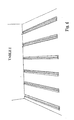
- a specific groove, or rail wherein the clasping slider moves, passes through the centre and all along the wooden base frame - Table I Fig.1 & Table IV Fig. 1.
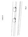
- the plastic (or nylon) slider has various functions: on the one hand the specific form of the base allows its movement along the rail - Table IV Fig.1, and on the other hand, thanks to a particular slider head that stand above the rail, each plank can be clasped on - Table III Fig.1 & 2.
- the plank in fact, has the two symmetric "U-shaped" edges, which fit in perfectly with the plastic slider head standing above the rail - Table III Fig.2.
- the plank is reversible, which means that it has two treadable surfaces.
- the other function of the plastic slider is to fix the distance between the planks - Table III Fig.2, for it is placed between two adjacent planks; in fact, every single slider head, except those fixed on the extremes of the wooden boards, houses and clasps two edges of two different planks. Thus, the distance between the two adjacent planks is predetermined by the slider.
- the slider made of nylon or another material, has a particular form adapted to the above described function; its dimensions may vary, but this does not change the basic idea of the invention.
- the three above described features constitute the primary elements of this innovative laying system. Their number and combination varies according to the surface to be wood-lined or paved but does not modify the process of the invention.
- the layer positions, at his discretion and side by side, the board framework - Table I Fig.1. Successively he inserts the first series of plastic sliders in each rail, one by one or all together - Table V Fig.1, reaching the most external edge of the wooden board - Table I fig.1.
- the first series of planks are placed perpendicularly to the boards; one of the two sides of each plank can be chosen thanks to their reversibility.
- the laying mode and sequence can be chosen at the layer's discretion. He could even choose to proceed differently from the way described above, which is simply an example, without modifying the invention procedure, the aim of which is to speed up the floor laying process and simplify the work of the layers, as well as to guarantee the resistance and stability of the flooring.
- the beneficial effects of the system with respect to the traditional methods are the rapidity of laying flooring, wooden lining or false ceilings for both exteriors and interiors, reducing laying time by 70-80%.
- Another characteristic of the system is the assembly and disassembly facility.
- Another characteristic is the resistance and stability of the flooring.
- Another characteristic is its adaptability to the laying of planks of any length or width.
- Another characteristic is that it employs almost entirely ecological materials, in fact the plastic slider represents just a tiny percentage with respect to the rest of the materials used, so a low environmental impact is guaranteed.
- plank reversibility that enables to have a new surface each time the old one is used up, worn out or no longer appreciated.
- the invention presents numerous advantages with respect to the present day state of the art in this field and offers a new and rapid way of laying wood floors, wood lining and false ceilings both for interiors and exteriors.
Landscapes
- Engineering & Computer Science (AREA)
- Architecture (AREA)
- Civil Engineering (AREA)
- Structural Engineering (AREA)
- Life Sciences & Earth Sciences (AREA)
- Wood Science & Technology (AREA)
- Floor Finish (AREA)
Abstract
Description
- Today there are various wood floor or parquet laying techniques. Along with the traditional assembly techniques, systems designed to simplify the floor layer's work are now being developed. Their aim is the prompt and simple laying of a floor without compromising its quality, resistance and durability.
- Among the assembly facilitating laying systems, wood flooring jointed by pressure to an expressly designed firm structure is beginning to be offered on the market. The jointed assembly is possible thanks to the particular form and structure of the base frame and that of the floor planks. A series of plastic supports are fixed on each board of the wooden base, forming the jointing base for the floor planks. Such supports actually require the use of special sliding-tongues to be clasped into the grooves of the plank.
- In particular, the plastic supports are fixed on the wooden board at a variable distance, or rather they are adjustable within certain limits depending on the width of the plank, and are so designed that the plank is jointed by exerting a considerable downwards pressure.
- Once the wooden boards are positioned side by side, the floor planks are joined perpendicularly to them by pressure, each plank covering two or more boards of the wooden base frame. The floor planks have a series of grooves that enable their jointing by pressure to the sliding tongues of the plastic support, thus giving stability to the system.
- This is clearly a rapid flooring assembly system, but it presents certain setbacks: the pressure exerted in the jointing may, in fact, damage the planks, thus limiting the system's application exclusively to hardwood planks, which are resistant and therefore heavy. Moreover, the plank cannot be reversed.
- The invention for which we require the industrial protection can be seen in Table I et seq., and consists in an innovative laying system for flooring, wood lining and wood false ceiling for exteriors and interiors.
- There are three basic elements of the system that, when properly coordinated, guarantee the simplicity and rapidity of floor laying, with reduction of assembly time, plank reversibility, flooring stability and resistance.
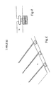
- These three elements are: a board framework in wood - Table V Fig.1(a), a plastic clasping slider - Table V Fig.1(b) and a reversible plank - Table III Fig.1 (a) & Fig. 2 (a).
- A specific groove, or rail wherein the clasping slider moves, passes through the centre and all along the wooden base frame - Table I Fig.1 & Table IV Fig. 1.
- The plastic (or nylon) slider has various functions: on the one hand the specific form of the base allows its movement along the rail - Table IV Fig.1, and on the other hand, thanks to a particular slider head that stand above the rail, each plank can be clasped on - Table III Fig.1 & 2. The plank, in fact, has the two symmetric "U-shaped" edges, which fit in perfectly with the plastic slider head standing above the rail - Table III Fig.2. The plank is reversible, which means that it has two treadable surfaces.
- The other function of the plastic slider is to fix the distance between the planks - Table III Fig.2, for it is placed between two adjacent planks; in fact, every single slider head, except those fixed on the extremes of the wooden boards, houses and clasps two edges of two different planks. Thus, the distance between the two adjacent planks is predetermined by the slider.
- The slider, made of nylon or another material, has a particular form adapted to the above described function; its dimensions may vary, but this does not change the basic idea of the invention.
- Thus, the three above described features constitute the primary elements of this innovative laying system. Their number and combination varies according to the surface to be wood-lined or paved but does not modify the process of the invention. In fact, the layer positions, at his discretion and side by side, the board framework - Table I Fig.1. Successively he inserts the first series of plastic sliders in each rail, one by one or all together - Table V Fig.1, reaching the most external edge of the wooden board - Table I fig.1. At this point, the first series of planks are placed perpendicularly to the boards; one of the two sides of each plank can be chosen thanks to their reversibility. The jointing occurs between the U-shaped edge of the plank and the slider head that stands above the rail - Table III Fig.2. Then a second series of sliders, which block the planks of the first series, is inserted on the "U-shaped" side opposite the first, using the same clasping technique between the plank edge and the slider head. The other planks are positioned following the same procedure and the same technique, until the entire surface to be wood lined or paved has been covered - Table II Fig.1.
- The laying mode and sequence can be chosen at the layer's discretion. He could even choose to proceed differently from the way described above, which is simply an example, without modifying the invention procedure, the aim of which is to speed up the floor laying process and simplify the work of the layers, as well as to guarantee the resistance and stability of the flooring.
- The beneficial effects of the system with respect to the traditional methods are the rapidity of laying flooring, wooden lining or false ceilings for both exteriors and interiors, reducing laying time by 70-80%.
- Another characteristic of the system is the assembly and disassembly facility.
- Another characteristic is the resistance and stability of the flooring.
- Another characteristic is its adaptability to the laying of planks of any length or width.
- Another characteristic is that it employs almost entirely ecological materials, in fact the plastic slider represents just a tiny percentage with respect to the rest of the materials used, so a low environmental impact is guaranteed.
- Another characteristic of the system is the plank reversibility, that enables to have a new surface each time the old one is used up, worn out or no longer appreciated.
- The invention presents numerous advantages with respect to the present day state of the art in this field and offers a new and rapid way of laying wood floors, wood lining and false ceilings both for interiors and exteriors.
- The discovery is not limited to the data shown in the tables, that should be considered solely as an example, but instead it could be modified by a professional worker, staying within the conceptual frame of the invention.
Claims (6)
- Laying system for flooring, wood lining and wood false ceilings for exteriors and interiors through the use of the three basic elements, that, when properly coordinated, provide laying rapidity, flooring resistance and stability. The three primary elements are the board framework, the plastic clasping slider and the reversible plank. The base is run across by a special rail along which the clasping slider moves. The plastic slider moves along the rail while its head, standing above the rail, enables the clasping of the plank. The plank with symmetrical U-shaped edges fits in perfectly with the plastic slider head and is reversible.
- Laying system for flooring, wood lining and wood false ceilings for exteriors and interiors as claimed in claim 1, characterised by the variable number of elements used, suitably jointed by the technical process, and that depends on the type of surface to be lined or paved.
- Laying system for flooring, wood lining and wood false ceilings for exteriors and interiors as claimed in claim 1 and 2, characterised by a slider of nylon or another material (aluminium), that has the function of fixing the distance between adjacent planks and the particular form of which guarantees both the movement along the rail on the board framework and the jointing of its head in the U-shaped edge of a plank; its dimensions may vary but this does not effect the base idea of the invention.
- Laying system for flooring, wood lining and wood false ceilings for exteriors and interiors as claimed in claim 1, 2 and 3 characterised by a simple, flexible and prompt assembly technique with consequent reduction of laying time, easy assembling and disassembling.
- Laying system for flooring, wood lining and wood false ceilings for exteriors and interiors as claimed in claim 1, 2, 3 and 4 characterised by a reversible wooden plank with two treadable surfaces, either smooth or nonslip.
- Laying system for flooring, wood lining and wood false ceilings for exteriors and interiors as claimed in claim 1, 2, 3, 4 and 5 characterised by very low environmental impact as a consequence of its employing almost entirely ecological materials.
Applications Claiming Priority (1)
| Application Number | Priority Date | Filing Date | Title |
|---|---|---|---|
| ITCS20050009 ITCS20050009A1 (en) | 2005-05-31 | 2005-05-31 | Rapid installation system for floors, walls and false ceilings in wood for exteriors and interiors. |
Publications (2)
| Publication Number | Publication Date |
|---|---|
| EP1728941A2 true EP1728941A2 (en) | 2006-12-06 |
| EP1728941A3 EP1728941A3 (en) | 2008-08-06 |
Family
ID=36933490
Family Applications (1)
| Application Number | Title | Priority Date | Filing Date |
|---|---|---|---|
| EP06425189A Withdrawn EP1728941A3 (en) | 2005-05-31 | 2006-03-21 | Laying system for making a wooden floor, wall or false ceiling |
Country Status (2)
| Country | Link |
|---|---|
| EP (1) | EP1728941A3 (en) |
| IT (1) | ITCS20050009A1 (en) |
Cited By (7)
| Publication number | Priority date | Publication date | Assignee | Title |
|---|---|---|---|---|
| CN101215891B (en) * | 2008-01-03 | 2010-04-14 | 王君 | Floor and ceiling fixing device |
| CN101240649B (en) * | 2008-01-03 | 2010-06-02 | 王君 | Sliding chute positioning link bar |
| WO2011006813A3 (en) * | 2009-07-13 | 2011-04-14 | Akzenta Paneele + Profile Gmbh | Mounting bracket and mounting rail and method for erecting a cladding surface |
| DE102011113064A1 (en) | 2011-09-09 | 2013-03-14 | Hans-Jürgen Schnaars | Method for laying boards for constructing e.g. walls, involves connecting lower side of boards with longitudinal beam by connection element insertable into upper-sided transverse grooves of beam and lower-sided longitudinal groove of beam |
| WO2014177945A1 (en) * | 2013-04-30 | 2014-11-06 | Torres Pinzon Roman | Fastening system for coatings for horizontal and vertical faces |
| CN107100338A (en) * | 2017-06-22 | 2017-08-29 | 嘉兴天美环保集成墙面有限公司 | A kind of assembled wall board being connected firmly |
| WO2024213804A1 (en) * | 2023-04-14 | 2024-10-17 | Control Y Desarrollo Empresarial, S.L. | Surface covering and fasteners for same |
Family Cites Families (4)
| Publication number | Priority date | Publication date | Assignee | Title |
|---|---|---|---|---|
| GB940664A (en) * | 1961-02-23 | 1963-10-30 | Ray Edward Omholt | Wooden floors |
| AT354036B (en) * | 1976-03-09 | 1979-12-10 | Tranker Kurt | WALL OR CEILING CLADDING |
| DE3316551A1 (en) * | 1983-05-06 | 1984-11-08 | Eugen 6750 Kaiserslautern Baumgärtner | Front lining for a wall or ceiling |
| BE1015672A3 (en) * | 2003-09-05 | 2005-07-05 | Buzon Pedestal Internat S A | Floor. |
-
2005
- 2005-05-31 IT ITCS20050009 patent/ITCS20050009A1/en unknown
-
2006
- 2006-03-21 EP EP06425189A patent/EP1728941A3/en not_active Withdrawn
Cited By (7)
| Publication number | Priority date | Publication date | Assignee | Title |
|---|---|---|---|---|
| CN101215891B (en) * | 2008-01-03 | 2010-04-14 | 王君 | Floor and ceiling fixing device |
| CN101240649B (en) * | 2008-01-03 | 2010-06-02 | 王君 | Sliding chute positioning link bar |
| WO2011006813A3 (en) * | 2009-07-13 | 2011-04-14 | Akzenta Paneele + Profile Gmbh | Mounting bracket and mounting rail and method for erecting a cladding surface |
| DE102011113064A1 (en) | 2011-09-09 | 2013-03-14 | Hans-Jürgen Schnaars | Method for laying boards for constructing e.g. walls, involves connecting lower side of boards with longitudinal beam by connection element insertable into upper-sided transverse grooves of beam and lower-sided longitudinal groove of beam |
| WO2014177945A1 (en) * | 2013-04-30 | 2014-11-06 | Torres Pinzon Roman | Fastening system for coatings for horizontal and vertical faces |
| CN107100338A (en) * | 2017-06-22 | 2017-08-29 | 嘉兴天美环保集成墙面有限公司 | A kind of assembled wall board being connected firmly |
| WO2024213804A1 (en) * | 2023-04-14 | 2024-10-17 | Control Y Desarrollo Empresarial, S.L. | Surface covering and fasteners for same |
Also Published As
| Publication number | Publication date |
|---|---|
| ITCS20050009A1 (en) | 2005-08-30 |
| EP1728941A3 (en) | 2008-08-06 |
Similar Documents
| Publication | Publication Date | Title |
|---|---|---|
| CA2570356C (en) | Multi-positionable wall or ceiling panel | |
| CA2366535C (en) | Glider bar for flooring system | |
| CN100375823C (en) | Floor and laying and manufacturing method thereof | |
| US8539731B2 (en) | Transition molding and installation methods therefor | |
| US7861483B2 (en) | Floor panel with the tongue more elastic than the locking element | |
| US20130042553A1 (en) | Reversible decorative moldings between floor and wall or wall and ceiling | |
| US4416100A (en) | Modular wooden floor units and method of manufacture thereof | |
| UA85821C2 (en) | Removable floor boarding | |
| BRPI0408688A (en) | device for connecting building boards, especially floor panels | |
| CA2941602A1 (en) | Floor vent | |
| ATE539206T1 (en) | USE OF A BUILDING WALL ELEMENT AND A WOOD LAYER COMPOSITE BOARD | |
| US11384545B2 (en) | Profile system for intersecting joints | |
| US20080163574A1 (en) | Fixing System for Finishing and Decorative Profiles | |
| RU2683970C1 (en) | Panel and panel bundle | |
| EP1728941A3 (en) | Laying system for making a wooden floor, wall or false ceiling | |
| US20040231271A1 (en) | Drop ceiling made of wood | |
| US20050252143A1 (en) | Hardwood flooring assembly system and method | |
| CN101360870A (en) | Laminate Floor Panels | |
| BE1014640A6 (en) | Hooked tooth and groove joint. | |
| US8225574B2 (en) | Methods of and apparatuses for hardwood floor installation | |
| EP1361319A1 (en) | Prefabricated flooring panel | |
| CN220226055U (en) | Floor convenient to install | |
| RU2338855C2 (en) | Structural element, in particular, panel, and also corresponding blank | |
| CA3080653A1 (en) | Wall panels having adhesive coating | |
| SE9702580L (en) | Procedure for laying floors |
Legal Events
| Date | Code | Title | Description |
|---|---|---|---|
| PUAI | Public reference made under article 153(3) epc to a published international application that has entered the european phase |
Free format text: ORIGINAL CODE: 0009012 |
|
| AK | Designated contracting states |
Kind code of ref document: A2 Designated state(s): AT BE BG CH CY CZ DE DK EE ES FI FR GB GR HU IE IS IT LI LT LU LV MC NL PL PT RO SE SI SK TR |
|
| AX | Request for extension of the european patent |
Extension state: AL BA HR MK YU |
|
| PUAL | Search report despatched |
Free format text: ORIGINAL CODE: 0009013 |
|
| AK | Designated contracting states |
Kind code of ref document: A3 Designated state(s): AT BE BG CH CY CZ DE DK EE ES FI FR GB GR HU IE IS IT LI LT LU LV MC NL PL PT RO SE SI SK TR |
|
| AX | Request for extension of the european patent |
Extension state: AL BA HR MK YU |
|
| STAA | Information on the status of an ep patent application or granted ep patent |
Free format text: STATUS: THE APPLICATION IS DEEMED TO BE WITHDRAWN |
|
| 18D | Application deemed to be withdrawn |
Effective date: 20081001 |