EP1727985B1 - Modular volumetric compressor - Google Patents
Modular volumetric compressor Download PDFInfo
- Publication number
- EP1727985B1 EP1727985B1 EP05716893A EP05716893A EP1727985B1 EP 1727985 B1 EP1727985 B1 EP 1727985B1 EP 05716893 A EP05716893 A EP 05716893A EP 05716893 A EP05716893 A EP 05716893A EP 1727985 B1 EP1727985 B1 EP 1727985B1
- Authority
- EP
- European Patent Office
- Prior art keywords
- delivery
- suction
- coupling element
- connection
- manufacturing
- Prior art date
- Legal status (The legal status is an assumption and is not a legal conclusion. Google has not performed a legal analysis and makes no representation as to the accuracy of the status listed.)
- Expired - Lifetime
Links
- 230000008878 coupling Effects 0.000 claims abstract description 40
- 238000010168 coupling process Methods 0.000 claims abstract description 40
- 238000005859 coupling reaction Methods 0.000 claims abstract description 40
- 238000004519 manufacturing process Methods 0.000 claims description 24
- 238000000034 method Methods 0.000 claims description 13
- 239000012530 fluid Substances 0.000 description 14
- 238000004378 air conditioning Methods 0.000 description 6
- 239000003921 oil Substances 0.000 description 6
- 238000005057 refrigeration Methods 0.000 description 6
- 238000010276 construction Methods 0.000 description 5
- QGZKDVFQNNGYKY-UHFFFAOYSA-N Ammonia Chemical compound N QGZKDVFQNNGYKY-UHFFFAOYSA-N 0.000 description 4
- 239000010687 lubricating oil Substances 0.000 description 4
- 238000009434 installation Methods 0.000 description 3
- 229910021529 ammonia Inorganic materials 0.000 description 2
- 238000001914 filtration Methods 0.000 description 1
- 238000005461 lubrication Methods 0.000 description 1
- 238000012986 modification Methods 0.000 description 1
- 230000004048 modification Effects 0.000 description 1
- 238000004513 sizing Methods 0.000 description 1
Images


Classifications
-
- F—MECHANICAL ENGINEERING; LIGHTING; HEATING; WEAPONS; BLASTING
- F04—POSITIVE - DISPLACEMENT MACHINES FOR LIQUIDS; PUMPS FOR LIQUIDS OR ELASTIC FLUIDS
- F04C—ROTARY-PISTON, OR OSCILLATING-PISTON, POSITIVE-DISPLACEMENT MACHINES FOR LIQUIDS; ROTARY-PISTON, OR OSCILLATING-PISTON, POSITIVE-DISPLACEMENT PUMPS
- F04C2/00—Rotary-piston machines or pumps
- F04C2/08—Rotary-piston machines or pumps of intermeshing-engagement type, i.e. with engagement of co-operating members similar to that of toothed gearing
- F04C2/082—Details specially related to intermeshing engagement type machines or pumps
-
- F—MECHANICAL ENGINEERING; LIGHTING; HEATING; WEAPONS; BLASTING
- F04—POSITIVE - DISPLACEMENT MACHINES FOR LIQUIDS; PUMPS FOR LIQUIDS OR ELASTIC FLUIDS
- F04C—ROTARY-PISTON, OR OSCILLATING-PISTON, POSITIVE-DISPLACEMENT MACHINES FOR LIQUIDS; ROTARY-PISTON, OR OSCILLATING-PISTON, POSITIVE-DISPLACEMENT PUMPS
- F04C23/00—Combinations of two or more pumps, each being of rotary-piston or oscillating-piston type, specially adapted for elastic fluids; Pumping installations specially adapted for elastic fluids; Multi-stage pumps specially adapted for elastic fluids
-
- F—MECHANICAL ENGINEERING; LIGHTING; HEATING; WEAPONS; BLASTING
- F04—POSITIVE - DISPLACEMENT MACHINES FOR LIQUIDS; PUMPS FOR LIQUIDS OR ELASTIC FLUIDS
- F04C—ROTARY-PISTON, OR OSCILLATING-PISTON, POSITIVE-DISPLACEMENT MACHINES FOR LIQUIDS; ROTARY-PISTON, OR OSCILLATING-PISTON, POSITIVE-DISPLACEMENT PUMPS
- F04C18/00—Rotary-piston pumps specially adapted for elastic fluids
- F04C18/08—Rotary-piston pumps specially adapted for elastic fluids of intermeshing-engagement type, i.e. with engagement of co-operating members similar to that of toothed gearing
- F04C18/12—Rotary-piston pumps specially adapted for elastic fluids of intermeshing-engagement type, i.e. with engagement of co-operating members similar to that of toothed gearing of other than internal-axis type
- F04C18/14—Rotary-piston pumps specially adapted for elastic fluids of intermeshing-engagement type, i.e. with engagement of co-operating members similar to that of toothed gearing of other than internal-axis type with toothed rotary pistons
- F04C18/16—Rotary-piston pumps specially adapted for elastic fluids of intermeshing-engagement type, i.e. with engagement of co-operating members similar to that of toothed gearing of other than internal-axis type with toothed rotary pistons with helical teeth, e.g. chevron-shaped, screw type
-
- F—MECHANICAL ENGINEERING; LIGHTING; HEATING; WEAPONS; BLASTING
- F04—POSITIVE - DISPLACEMENT MACHINES FOR LIQUIDS; PUMPS FOR LIQUIDS OR ELASTIC FLUIDS
- F04C—ROTARY-PISTON, OR OSCILLATING-PISTON, POSITIVE-DISPLACEMENT MACHINES FOR LIQUIDS; ROTARY-PISTON, OR OSCILLATING-PISTON, POSITIVE-DISPLACEMENT PUMPS
- F04C2230/00—Manufacture
- F04C2230/60—Assembly methods
-
- F—MECHANICAL ENGINEERING; LIGHTING; HEATING; WEAPONS; BLASTING
- F04—POSITIVE - DISPLACEMENT MACHINES FOR LIQUIDS; PUMPS FOR LIQUIDS OR ELASTIC FLUIDS
- F04C—ROTARY-PISTON, OR OSCILLATING-PISTON, POSITIVE-DISPLACEMENT MACHINES FOR LIQUIDS; ROTARY-PISTON, OR OSCILLATING-PISTON, POSITIVE-DISPLACEMENT PUMPS
- F04C2240/00—Components
- F04C2240/70—Use of multiplicity of similar components; Modular construction
-
- F—MECHANICAL ENGINEERING; LIGHTING; HEATING; WEAPONS; BLASTING
- F04—POSITIVE - DISPLACEMENT MACHINES FOR LIQUIDS; PUMPS FOR LIQUIDS OR ELASTIC FLUIDS
- F04C—ROTARY-PISTON, OR OSCILLATING-PISTON, POSITIVE-DISPLACEMENT MACHINES FOR LIQUIDS; ROTARY-PISTON, OR OSCILLATING-PISTON, POSITIVE-DISPLACEMENT PUMPS
- F04C23/00—Combinations of two or more pumps, each being of rotary-piston or oscillating-piston type, specially adapted for elastic fluids; Pumping installations specially adapted for elastic fluids; Multi-stage pumps specially adapted for elastic fluids
- F04C23/008—Hermetic pumps
-
- Y—GENERAL TAGGING OF NEW TECHNOLOGICAL DEVELOPMENTS; GENERAL TAGGING OF CROSS-SECTIONAL TECHNOLOGIES SPANNING OVER SEVERAL SECTIONS OF THE IPC; TECHNICAL SUBJECTS COVERED BY FORMER USPC CROSS-REFERENCE ART COLLECTIONS [XRACs] AND DIGESTS
- Y10—TECHNICAL SUBJECTS COVERED BY FORMER USPC
- Y10T—TECHNICAL SUBJECTS COVERED BY FORMER US CLASSIFICATION
- Y10T29/00—Metal working
- Y10T29/49—Method of mechanical manufacture
- Y10T29/49229—Prime mover or fluid pump making
- Y10T29/49236—Fluid pump or compressor making
Definitions
- the present invention concerns a volumetric compressor, particularly suited to be used in air conditioning and/or refrigeration systems.
- volumetric compressors are used, which are suitable for circulating a carrier fluid inside a closed circuit for air conditioning in closed spaces or for the refrigeration of cold rooms and similar structures.
- volumetric compressors manufactured according to the prior art are all constituted by a casing in which it is possible to identify a carrier fluid suction chamber, provided with a suction valve and a carrier fluid delivery chamber, provided with a delivery valve, with a pair of screw rotors included between them.
- volumetric compressors are available on the market; in particular, when they are used for the construction of air conditioning systems, they are provided, inside the casing, with a semi-hermetic motor unit for the operation of the rotors and with a lubricating oil separator positioned before the delivery valve.
- volumetric compressors indeed, are equipped with a hydraulic circuit for the lubrication of the rotors that is suited to improve their efficiency; the lubricating oil is mixed with the carrier fluid inside the compressor and consequently it must be separated from the latter before being conveyed to the air conditioning circuit
- volumetric compressors similar to those described above, are generally used, that is, compressors comprising a casing inside which there is a semi-hermetic motor unit including a suction chamber provided with a suction valve and a delivery chamber provided with a delivery valve, with a pair of screw rotors included between them, in which, however, there is no lubricating oil separator.
- volumetric compressor used for example for particularly aggressive fluids like ammonia, differs from those previously described owing to the fact that it is not provided with a motor unit inside the compressor casing.
- the compressor called “open type” compressor, is equipped with drive and coupling means for connection to an external motor unit for the operation of the rotors.
- US 4,780,061 discloses a screw compressor assembly comprising an oil separator downstream of the compressor discharge port.
- the main drawback is represented by the fact that in order to meet the customer's different needs, according to the combinations described above, the manufacturer must produce different compressors.
- a further drawback is represented by the fact that if the customer needs a compressor with a configuration different from the one installed, he should obviously replace it with a new one capable of satisfying the new requirements of the system.
- a situation of this kind occurs, for example, if the customer needs to pass from an external motor unit to a semi-hermetic motor unit associated with the suction head of the compressor.
- the present invention aims to eliminate all the drawbacks listed above.
- the possibility to connect the same compressor body to two different types of suction head on the suction side and to two different types of delivery head on the delivery side makes it possible to achieve all the compressor configurations required by the market, using five different components, instead of making four separate compressors.
- the possibility to removably connect the suction and delivery heads to the compressor body, through a connection with flange and counterflange, allows the configuration of the compressor to be modified even after its first installation.
- the volumetric compressor of the invention comprises a pair of rotors 2 cooperating with each other and housed inside a compressor body 3 in which it is possible to identify a first flange 4 arranged on the suction side of said compressor body 3 and a second flange 5 arranged on the delivery side of said compressor body 3 , said first flange 4 being suited to be coupled with a suction head 6, 7 and said second flange 5 being suited to be coupled with a delivery head 8, 9 of said volumetric compressor 1 .
- the suction head 6, 7 is provided with a first counterflange 10, 11 suited to be connected to said first flange 4 and includes a coupling element 12 for connection to a suction pipe, or a coupling element 13 for connection to a suction pipe in combination with a motor unit 14, and said delivery head 8, 9 is provided with a second counterflange 15, 16 suited to be connected to said second flange 5 and includes a coupling element 17 for connection to a delivery pipe, or a coupling element 18 for connection to a delivery pipe in combination with an oil separator 19.
- Figures from 2 to 5 show the different configurations 50, 60, 70, 80 of the compressor 1 of the invention, that can be achieved by connecting to the compressor body 3 the different suction heads 8, 9 and delivery heads 10, 11 shown in Figure 1, by fastening each flange 4, 5 of the compressor body 3 to the counterflange 10, 11, 15, 16 of the suction head 6, 7 or of the delivery head 8, 9 .
- Figure 2 shows the configuration 50 that involves the installation, on the suction side of the compressor body 3 , of a head 7 comprising a coupling element 13 for connection to a suction pipe in combination with a motor unit 14 , preferably but not necessarily semi-hermetic, while on the delivery side of the compressor body 3 there is a head 8 comprising a coupling element 18 for connection to a delivery pipe in combination with an oil separator 19 .
- the semi-hermetic motor unit 14 that operates the rotors 2 housed inside the compressor body 3 , this is generally constituted by an electric motor cooled by the carrier fluid itself.
- each volumetric compressor 80 is equipped with an independent, semi-hermetic motor unit 14, while the filtration of the carrier fluid takes place in a common external oil separator that serves all the compressors making up the system, towards which all the delivery pipes of each compressor converge.
- volumetric compressors 80 of the type shown in Figure 5 are used, in which the suction head 7 , connected to the compressor body 3 on the suction side, comprises the coupling element 13 in combination with the motor unit 14 , while the delivery head 9 connected to the compressor body 3 on the delivery side comprises only the delivery valve conveying the carrier fluid to the external oil separator.
- Figure 4 shows a further configuration 70 of the volumetric compressor 1 of the invention, in which the suction head 8 , connected to the compressor body 3 on the suction side, comprises only the coupling element 12 for connection to a suction pipe, while the delivery head 8 connected to the compressor body 3 on the delivery side comprises the coupling element 18 for connection to a delivery pipe in combination with the oil separator 19 .
- the last configuration 60 of the compressor 1 of the invention is that shown in Figure 3, in which the suction head 6 connected to the compressor body 3 on the suction side comprises only the coupling element 12 for connection to a carrier fluid suction pipe, while the delivery head 9 , connected to the compressor body 3 on the delivery side, comprises only the coupling element 17 for connection to a carrier fluid delivery pipe.
- the suction head 6 is equipped with drive means 20 suited to be set in motion by the motor unit of the system and to transmit motion to the rotors 2 housed inside the compressor body 3 .
- This type of compressor 60 is particularly suited to be installed in systems that use particularly aggressive carrier fluids, for example ammonia, which may damage the motor unit in case of contact with the latter.
- particularly aggressive carrier fluids for example ammonia
- this may be sized according to the power required and to the type of carrier fluid used in the circuit, though maintaining a first flange 4 , arranged on the suction side, and a second flange 5 , arranged on the delivery side, suited to house corresponding counterflanges 10, 11, 15, 16 for the connection of the suction heads 6, 7 and the delivery heads 8, 9 shown in Figure 1.
- the sizing of the compressor body 3 is generally achieved by varying the longitudinal development of the rotors 2 housed inside it and consequently the longitudinal development of the compressor body itself.
- volumetric compressor 1, 50, 60, 70, 80 in which it is substantially possible to identify three interchangeable functional units, that is, a compressor body 3, a suction head 6, 7 and a delivery head 8, 9, makes the compressor 1, 50, 60, 70, 80 of the invention modular and, therefore, easy to be adapted to the different needs of the user, simply by assembling the components in different ways.
- the coupling element 12, 13 for connection to a suction pipe for the carrier fluid at low pressure and the coupling element 17,18 for connection to a delivery pipe for the carrier fluid at high pressure may be constituted, according to the customer's needs, by a suction and/or delivery valve or, alternatively, by a suction and/or delivery coupling.
- connection of the suction heads 6, 7 and delivery heads 8, 9 to the compressor body 3 it takes place through a coupling between flange 4, 5 and counterflange 10, 11, 15, 16 that is made integral through suitable fastening means 21 of the known type, for example screws.
- volumetric compressor of the invention achieves all the aims set.
Landscapes
- Engineering & Computer Science (AREA)
- Mechanical Engineering (AREA)
- General Engineering & Computer Science (AREA)
- Compressor (AREA)
- Applications Or Details Of Rotary Compressors (AREA)
- Structures Of Non-Positive Displacement Pumps (AREA)
Abstract
Description
- The present invention concerns a volumetric compressor, particularly suited to be used in air conditioning and/or refrigeration systems.
- It is known that in air conditioning and/or refrigeration systems volumetric compressors are used, which are suitable for circulating a carrier fluid inside a closed circuit for air conditioning in closed spaces or for the refrigeration of cold rooms and similar structures.
- Though in their different specific applications, the volumetric compressors manufactured according to the prior art are all constituted by a casing in which it is possible to identify a carrier fluid suction chamber, provided with a suction valve and a carrier fluid delivery chamber, provided with a delivery valve, with a pair of screw rotors included between them.
- For the different applications mentioned above, different types of volumetric compressors are available on the market; in particular, when they are used for the construction of air conditioning systems, they are provided, inside the casing, with a semi-hermetic motor unit for the operation of the rotors and with a lubricating oil separator positioned before the delivery valve.
- Volumetric compressors, indeed, are equipped with a hydraulic circuit for the lubrication of the rotors that is suited to improve their efficiency; the lubricating oil is mixed with the carrier fluid inside the compressor and consequently it must be separated from the latter before being conveyed to the air conditioning circuit
- For the refrigeration systems, on the other hand, volumetric compressors, similar to those described above, are generally used, that is, compressors comprising a casing inside which there is a semi-hermetic motor unit including a suction chamber provided with a suction valve and a delivery chamber provided with a delivery valve, with a pair of screw rotors included between them, in which, however, there is no lubricating oil separator.
- In the refrigeration systems, indeed, two or more compressors arranged in parallel are often used, and a single lubricating oil separator is used for all the compressors making up the system.
- A further possible configuration of the volumetric compressor, used for example for particularly aggressive fluids like ammonia, differs from those previously described owing to the fact that it is not provided with a motor unit inside the compressor casing.
- In this case the compressor, called "open type" compressor, is equipped with drive and coupling means for connection to an external motor unit for the operation of the rotors.
-
US 4,780,061 discloses a screw compressor assembly comprising an oil separator downstream of the compressor discharge port. - The known volumetric compressors mentioned above, however, have some drawbacks that have been recognised as such.
- The main drawback is represented by the fact that in order to meet the customer's different needs, according to the combinations described above, the manufacturer must produce different compressors.
- Another drawback, connected to the previous one, is represented by the fact that, to obtain the constructional differences necessary to implement all the combinations mentioned and, therefore, to design and manufacture the different types of compressors, too many persons and means are required.
- A further drawback is represented by the fact that if the customer needs a compressor with a configuration different from the one installed, he should obviously replace it with a new one capable of satisfying the new requirements of the system.
- A situation of this kind occurs, for example, if the customer needs to pass from an external motor unit to a semi-hermetic motor unit associated with the suction head of the compressor.
- The present invention aims to eliminate all the drawbacks listed above.
- It is a first aim of the invention to carry out a volumetric compressor that makes it possible to reduce the number of components required to obtain all the types of compressor described by unifying their common parts.
- It is another aim of the invention to carry out a volumetric compressor whose construction technique can be simplified compared to the prior art, with consequent reduction in design and construction costs.
- It is a further aim of the invention to carry out a volumetric compressor that may be modified during manufacture with no need to replace it if its configuration must be changed.
- The aims described above have been achieved through the method of manufacturing and assembling a volumetric compressor according to claim 1.
- Advantageously, the possibility to connect the same compressor body to two different types of suction head on the suction side and to two different types of delivery head on the delivery side makes it possible to achieve all the compressor configurations required by the market, using five different components, instead of making four separate compressors.
- Still advantageously, the possibility to removably connect the suction and delivery heads to the compressor body, through a connection with flange and counterflange, allows the configuration of the compressor to be modified even after its first installation.
- The aims and advantages mentioned above will be highlighted in greater detail in the description of a favourite application of the invention, given as an example without limitation with reference to the enclosed drawings, wherein:
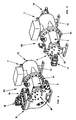
- Figure 1 is an exploded view of all the components of the volumetric compressor of the invention;
- Figures from 2 to 5 show different executive embodiments of the compressor of the invention, that can be obtained using the components shown in Figure 1.
- As can be observed in Figure 1, the volumetric compressor of the invention, indicated as a whole by 1, comprises a pair of rotors 2 cooperating with each other and housed inside a
compressor body 3 in which it is possible to identify a first flange 4 arranged on the suction side of saidcompressor body 3 and asecond flange 5 arranged on the delivery side of saidcompressor body 3, said first flange 4 being suited to be coupled with asuction head second flange 5 being suited to be coupled with adelivery head - According to the invention, the
suction head first counterflange coupling element 12 for connection to a suction pipe, or acoupling element 13 for connection to a suction pipe in combination with amotor unit 14, and saiddelivery head second counterflange second flange 5 and includes acoupling element 17 for connection to a delivery pipe, or acoupling element 18 for connection to a delivery pipe in combination with anoil separator 19. - Figures from 2 to 5 show the
different configurations compressor body 3 thedifferent suction heads delivery heads flange 4, 5 of thecompressor body 3 to thecounterflange suction head delivery head - In particular, Figure 2 shows the
configuration 50 that involves the installation, on the suction side of thecompressor body 3, of ahead 7 comprising acoupling element 13 for connection to a suction pipe in combination with amotor unit 14, preferably but not necessarily semi-hermetic, while on the delivery side of thecompressor body 3 there is ahead 8 comprising acoupling element 18 for connection to a delivery pipe in combination with anoil separator 19. - This type of configuration is the most widespread in air conditioning systems that must be equipped with a
compressor 50 with compact dimensions that integrates all the elements necessary for the operation of the circuit which generally requires one compressor only. - As to the
semi-hermetic motor unit 14 that operates the rotors 2 housed inside thecompressor body 3, this is generally constituted by an electric motor cooled by the carrier fluid itself. - For the refrigeration of cold rooms and similar structures, in order to achieve the performance required by the system it is often necessary to use a certain number of
compressors 80 arranged in series. - In this case, each
volumetric compressor 80 is equipped with an independent,semi-hermetic motor unit 14, while the filtration of the carrier fluid takes place in a common external oil separator that serves all the compressors making up the system, towards which all the delivery pipes of each compressor converge. - Thus, for this type of system,
volumetric compressors 80 of the type shown in Figure 5 are used, in which thesuction head 7, connected to thecompressor body 3 on the suction side, comprises thecoupling element 13 in combination with themotor unit 14, while thedelivery head 9 connected to thecompressor body 3 on the delivery side comprises only the delivery valve conveying the carrier fluid to the external oil separator. - Figure 4 shows a
further configuration 70 of the volumetric compressor 1 of the invention, in which thesuction head 8, connected to thecompressor body 3 on the suction side, comprises only thecoupling element 12 for connection to a suction pipe, while thedelivery head 8 connected to thecompressor body 3 on the delivery side comprises thecoupling element 18 for connection to a delivery pipe in combination with theoil separator 19. - The
last configuration 60 of the compressor 1 of the invention, that can be obtained with thecomponents suction head 6 connected to thecompressor body 3 on the suction side comprises only thecoupling element 12 for connection to a carrier fluid suction pipe, while thedelivery head 9, connected to thecompressor body 3 on the delivery side, comprises only thecoupling element 17 for connection to a carrier fluid delivery pipe. - The
suction head 6 is equipped with drive means 20 suited to be set in motion by the motor unit of the system and to transmit motion to the rotors 2 housed inside thecompressor body 3. - This type of
compressor 60 is particularly suited to be installed in systems that use particularly aggressive carrier fluids, for example ammonia, which may damage the motor unit in case of contact with the latter. - As to the
compressor body 3, this may be sized according to the power required and to the type of carrier fluid used in the circuit, though maintaining a first flange 4, arranged on the suction side, and asecond flange 5, arranged on the delivery side, suited to housecorresponding counterflanges suction heads delivery heads - The sizing of the
compressor body 3 is generally achieved by varying the longitudinal development of the rotors 2 housed inside it and consequently the longitudinal development of the compressor body itself. - Thus, it is obvious that, by combining compressor bodies of different sizes with the
suction heads delivery heads - The possibility to have a
volumetric compressor compressor body 3, asuction head delivery head compressor - As to the
coupling element coupling element - As to the connection of the
suction heads delivery heads compressor body 3, it takes place through a coupling betweenflange 4, 5 andcounterflange - According to the above, it can be understood that the volumetric compressor of the invention achieves all the aims set.
- In particular, it is achieved the aim to carry out a method of manufacturing and assembling of a volumetric compressor in which, owing to its modular nature, the number of components necessary to obtain the different configurations required by the users is reduced.
- It is also achieved the aim to carry out a method of manufacturing and assembling of a volumetric compressor whose construction technique can be simplified compared to the prior art, thus obtaining a reduction in design and construction costs.
- Finally, it is also achieved the aim to carry out a method of manufacturing and assembling of a volumetric compressor whose configuration may be modified even after its first installation to meet, for example, new needs of the system, or to be reinstalled in a new system.
- Upon implementation, modifications and changes that are neither described nor represented may be made to a method of manufacturing and assembling of the volumetric compressor object of the invention.
- The embodiments described and any other that have not been mentioned are to be considered protected by the present patent, provided that they fall within the scope of the claims expressed below.
Claims (13)
- Method of manufacturing and assembling, in function of the desired configurations, a volumetric compressor (1; 50; 60; 70; 80) of the type comprising a pair of rotors (2) cooperating with each other and housed inside a compressor body (3), said compressor body having a first flange (4) arranged on the suction side of said compressor body (3) and a second flange (5) arranged on the delivery side of said compressor body (3), said first flange (4) being suited to be coupled with a suction head, (6, 7) and said second flange (5) being suited to be coupled with a delivery head (8, 9) of said volumetric compressor (1), characterized by comprising the following operations:- manufacturing a first suction head (6) comprising a coupling element (12) to a suction pipe, and- manufacturing a second suction head (7) comprising a coupling element (13) for connection to a suction pipe in combination with a motor unit (14),- each of said first and second suction heads (6, 7) being provided with a first counterflange (10, 11), suited to be connected with said first flange (4) of said compressor body (3);- manufacturing a first delivery head (8) comprising a coupling element (17) to a delivery pipe, and- manufacturing a second delivery head (9) comprising a coupling element (18) for connection to a delivery pipe in combination with an oil separator (19),- each of said first and second delivery heads (8, 9) being provided with a second counterflange (15, 16) suited to be connected with said second flange (5) of said compressor body (3);- coupling said first flange (4) of said compressor body (3) with said counterflange (10, 11) of any of these first or second suction heads (6, 7);- coupling, said second flange (5) of said compressor body (3) with said counterflange (15, 16) of any of these first or second delivery heads (8, 9).
- Method of manufacturing and assembling according to the method of claim 1), characterized in that said first suction head (6) comprises a coupling element (12) for connection to a suction pipe, and said second delivery head (9) comprises a coupling element (17) for connection to a delivery pipe.
- Method of manufacturing and assembling according to the method of claim 1), characterized in that said first suction head (6) comprises a coupling element (12) for connection to a suction pipe, and said first delivery head (8) comprises a coupling element (18) for connection to a delivery pipe in combination with an oil separator (19).
- Method of manufacturing and assembling according to the method of claim 1), characterized in that said second suction head (7) comprises a coupling element (13) for connection to a suction pipe in combination with a motor unit (14), and said second delivery head (9) comprises a coupling element (17) for connection to a delivery pipe.
- Method of manufacturing and assembling according to the method of claim 1), characterized in that said second suction head (7) comprises a coupling element (13) for connection to a suction pipe in combination with a motor unit (14), and said first delivery head (8) comprises a coupling element (18) for connection to a delivery pipe in combination with an oil separator(19).
- Method of manufacturing and assembling according to the method of claim 1), characterized in that said coupling element (12, 13) for connection to a suction pipe is constituted by a suction valve.
- Method of manufacturing and assembling according to the method of claim 1), characterized in that said coupling element (12, 13) for connection to a suction pipe is constituted by a suction coupling.
- Method of manufacturing and assembling according to the method of claim 1), characterized in that said coupling element (17, 18) for connection to a delivery pipe is constituted by a delivery valve.
- Method of manufacturing and assembling according to the method of claim 1), characterized in that said coupling element (17, 18) for connection to a delivery pipe is constituted by a delivery coupling.
- Method of manufacturing and assembling according to the method of claim 1), characterized in that said motor unit (14) is of the semi-hermetic type.
- Method of manufacturing and assembling according to the method of claim 1), characterized in that it comprises fastening means (21) suited to permanently connect said first and second flange (4, 5) to said first and second counterflange (10, 11, 15, 16), respectively.
- Method of manufacturing and assembling according to claim 11), characterized in that said fastening means (21) are constituted by screws.
- Method of manufacturing and assembling according to the method of claim 1), characterized in that said motor unit (14) is constituted by an electric motor.
Applications Claiming Priority (2)
| Application Number | Priority Date | Filing Date | Title |
|---|---|---|---|
| IT000035A ITVI20040035A1 (en) | 2004-03-04 | 2004-03-04 | MODULAR VOLUMETRIC COMPRESSOR |
| PCT/EP2005/050936 WO2005085642A1 (en) | 2004-03-04 | 2005-03-03 | Modular volumetric compressor |
Publications (2)
| Publication Number | Publication Date |
|---|---|
| EP1727985A1 EP1727985A1 (en) | 2006-12-06 |
| EP1727985B1 true EP1727985B1 (en) | 2007-09-05 |
Family
ID=34917563
Family Applications (1)
| Application Number | Title | Priority Date | Filing Date |
|---|---|---|---|
| EP05716893A Expired - Lifetime EP1727985B1 (en) | 2004-03-04 | 2005-03-03 | Modular volumetric compressor |
Country Status (7)
| Country | Link |
|---|---|
| US (1) | US20070269325A1 (en) |
| EP (1) | EP1727985B1 (en) |
| CN (1) | CN1930395A (en) |
| AT (1) | ATE372463T1 (en) |
| DE (1) | DE602005002356D1 (en) |
| IT (1) | ITVI20040035A1 (en) |
| WO (1) | WO2005085642A1 (en) |
Families Citing this family (10)
| Publication number | Priority date | Publication date | Assignee | Title |
|---|---|---|---|---|
| DE102006058355A1 (en) * | 2006-03-10 | 2007-09-13 | Brueninghaus Hydromatik Gmbh | Combi pump housing for several nominal sizes |
| US7695259B2 (en) | 2006-09-21 | 2010-04-13 | Eaton Corporation | Rotary fluid pressure device with modular multi-speed control mechanism |
| DE102006062065A1 (en) * | 2006-12-29 | 2008-07-03 | Robert Bosch Gmbh | Hydrostatic axial piston machine e.g. swash plate machine, has periphery wall with radial elevation formed in longitudinal direction of housing and formed by two periphery wall sections that limit radially extended interior section |
| DE202009012158U1 (en) | 2009-09-08 | 2011-02-03 | Hugo Vogelsang Maschinenbau Gmbh | Rotary pump |
| DE202010011626U1 (en) * | 2010-08-20 | 2010-10-21 | Hugo Vogelsang Maschinenbau Gmbh | Rotary pump |
| DE102011014961A1 (en) * | 2011-03-24 | 2012-09-27 | Rotorcomp Verdichter Gmbh | Screw compressor system |
| WO2017027657A1 (en) | 2015-08-11 | 2017-02-16 | Carrier Corporation | Screw compressor economizer plenum for pulsation reduction |
| US10830239B2 (en) | 2015-08-11 | 2020-11-10 | Carrier Corporation | Refrigeration compressor fittings |
| US10941776B2 (en) | 2015-10-02 | 2021-03-09 | Carrier Corporation | Screw compressor resonator arrays |
| CN111608907B (en) * | 2020-05-13 | 2021-04-27 | 东风汽车集团有限公司 | A modular gearbox electric oil pump |
Family Cites Families (11)
| Publication number | Priority date | Publication date | Assignee | Title |
|---|---|---|---|---|
| US1796440A (en) * | 1928-01-20 | 1931-03-17 | Niels A Christensen | Compressor-valve mechanism |
| US2168036A (en) * | 1938-01-19 | 1939-08-01 | Maniscalco Pietro | Compressor |
| US2668004A (en) * | 1948-03-02 | 1954-02-02 | American Brake Shoe Co | Compressor |
| US2999629A (en) * | 1959-04-23 | 1961-09-12 | Worthington Corp | Interchangeable, hermetic and opentype refrigeration compressor |
| US3088660A (en) * | 1960-08-23 | 1963-05-07 | Ingersoll Rand Co | Rotary air compressor |
| US3407996A (en) * | 1966-06-22 | 1968-10-29 | Atlas Copco Ab | Screw compressor units |
| US4236876A (en) * | 1979-07-30 | 1980-12-02 | Carrier Corporation | Multiple compressor system |
| US4780061A (en) * | 1987-08-06 | 1988-10-25 | American Standard Inc. | Screw compressor with integral oil cooling |
| JPH04159480A (en) * | 1990-10-19 | 1992-06-02 | Hitachi Ltd | screw compressor |
| US5220784A (en) * | 1991-06-27 | 1993-06-22 | Allied-Signal Inc. | Gas turbine engine module assembly |
| DE4426761C2 (en) * | 1994-07-22 | 2003-07-17 | Grasso Gmbh Refrigeration Tech | screw compressors |
-
2004
- 2004-03-04 IT IT000035A patent/ITVI20040035A1/en unknown
-
2005
- 2005-03-03 US US10/591,387 patent/US20070269325A1/en not_active Abandoned
- 2005-03-03 WO PCT/EP2005/050936 patent/WO2005085642A1/en not_active Ceased
- 2005-03-03 DE DE602005002356T patent/DE602005002356D1/en not_active Expired - Lifetime
- 2005-03-03 CN CNA2005800070253A patent/CN1930395A/en active Pending
- 2005-03-03 EP EP05716893A patent/EP1727985B1/en not_active Expired - Lifetime
- 2005-03-03 AT AT05716893T patent/ATE372463T1/en not_active IP Right Cessation
Non-Patent Citations (1)
| Title |
|---|
| None * |
Also Published As
| Publication number | Publication date |
|---|---|
| CN1930395A (en) | 2007-03-14 |
| ATE372463T1 (en) | 2007-09-15 |
| DE602005002356D1 (en) | 2007-10-18 |
| WO2005085642A1 (en) | 2005-09-15 |
| ITVI20040035A1 (en) | 2004-06-04 |
| US20070269325A1 (en) | 2007-11-22 |
| EP1727985A1 (en) | 2006-12-06 |
Similar Documents
| Publication | Publication Date | Title |
|---|---|---|
| CN114555947B (en) | Screw compressor with adjustable passages | |
| US8622725B2 (en) | Mechanical compression ratio changing screw compressor | |
| US20070269325A1 (en) | Modular Volumetric Compressor | |
| EP3084222B1 (en) | Compressor comprising a variable volume index valve | |
| EP3722609B1 (en) | Screw compressor and air conditioning unit | |
| EP3392507B1 (en) | Variable-capacity cylinder with sliding vane control structure and variable-capacity compressor | |
| EP1457679A2 (en) | Screw compressor capable of manually adjusting both internal volume ratio and capacity | |
| EP1664529A2 (en) | Compact compressor | |
| KR20070083469A (en) | Screw compressor seal | |
| JP2003232285A (en) | Scroll type compressor | |
| EP1553302A3 (en) | Rotary vane compressor | |
| US7165947B2 (en) | Screw compressor capable of manually adjusting both internal volume ratio and capacity and combined screw compressor unit accommodating variation in suction or discharge pressure | |
| US8342829B2 (en) | Three-stage screw compressor | |
| CN114992363A (en) | Integrated throttling relief valve and compressor comprising same | |
| CN114215749A (en) | Screw rotor, compressor and air conditioner | |
| CN101778999B (en) | Screw compressor with integral bearing cover and discharge plenum divider | |
| CN105351195A (en) | Intermediate-back-pressure compressor, air conditioner with intermediate-back-pressure compressor and heat pump water heater with intermediate-back-pressure compressor | |
| CN205064273U (en) | Rolling Rotor Compressor | |
| US20080166247A1 (en) | Single-Shaft Vacuum Positive Displacement Pump | |
| CN109340112B (en) | Compressor and air conditioner | |
| JP4370130B2 (en) | Flow control mechanism and compressor | |
| CN107923398A (en) | Refrigeration compressor accessories | |
| JP2003232287A (en) | Scroll type compressor | |
| JPH04111583U (en) | rotating vane pump | |
| HK1146418B (en) | Screw compressor with integral bearing cover and discharge plenum divider |
Legal Events
| Date | Code | Title | Description |
|---|---|---|---|
| PUAI | Public reference made under article 153(3) epc to a published international application that has entered the european phase |
Free format text: ORIGINAL CODE: 0009012 |
|
| 17P | Request for examination filed |
Effective date: 20061004 |
|
| AK | Designated contracting states |
Kind code of ref document: A1 Designated state(s): AT BE BG CH CY CZ DE DK EE ES FI FR GB GR HU IE IS IT LI LT LU MC NL PL PT RO SE SI SK TR |
|
| GRAP | Despatch of communication of intention to grant a patent |
Free format text: ORIGINAL CODE: EPIDOSNIGR1 |
|
| DAX | Request for extension of the european patent (deleted) | ||
| GRAS | Grant fee paid |
Free format text: ORIGINAL CODE: EPIDOSNIGR3 |
|
| GRAA | (expected) grant |
Free format text: ORIGINAL CODE: 0009210 |
|
| RIN1 | Information on inventor provided before grant (corrected) |
Inventor name: TONIN, ANDREA Inventor name: FACCIO, ENRICO Inventor name: CANDIO, GIANNI |
|
| AK | Designated contracting states |
Kind code of ref document: B1 Designated state(s): AT BE BG CH CY CZ DE DK EE ES FI FR GB GR HU IE IS IT LI LT LU MC NL PL PT RO SE SI SK TR |
|
| REG | Reference to a national code |
Ref country code: GB Ref legal event code: FG4D |
|
| REG | Reference to a national code |
Ref country code: CH Ref legal event code: EP |
|
| REF | Corresponds to: |
Ref document number: 602005002356 Country of ref document: DE Date of ref document: 20071018 Kind code of ref document: P |
|
| REG | Reference to a national code |
Ref country code: IE Ref legal event code: FG4D |
|
| PG25 | Lapsed in a contracting state [announced via postgrant information from national office to epo] |
Ref country code: ES Free format text: LAPSE BECAUSE OF FAILURE TO SUBMIT A TRANSLATION OF THE DESCRIPTION OR TO PAY THE FEE WITHIN THE PRESCRIBED TIME-LIMIT Effective date: 20071216 Ref country code: FI Free format text: LAPSE BECAUSE OF FAILURE TO SUBMIT A TRANSLATION OF THE DESCRIPTION OR TO PAY THE FEE WITHIN THE PRESCRIBED TIME-LIMIT Effective date: 20070905 Ref country code: LT Free format text: LAPSE BECAUSE OF FAILURE TO SUBMIT A TRANSLATION OF THE DESCRIPTION OR TO PAY THE FEE WITHIN THE PRESCRIBED TIME-LIMIT Effective date: 20070905 |
|
| PG25 | Lapsed in a contracting state [announced via postgrant information from national office to epo] |
Ref country code: PL Free format text: LAPSE BECAUSE OF FAILURE TO SUBMIT A TRANSLATION OF THE DESCRIPTION OR TO PAY THE FEE WITHIN THE PRESCRIBED TIME-LIMIT Effective date: 20070905 Ref country code: LI Free format text: LAPSE BECAUSE OF FAILURE TO SUBMIT A TRANSLATION OF THE DESCRIPTION OR TO PAY THE FEE WITHIN THE PRESCRIBED TIME-LIMIT Effective date: 20070905 Ref country code: CH Free format text: LAPSE BECAUSE OF FAILURE TO SUBMIT A TRANSLATION OF THE DESCRIPTION OR TO PAY THE FEE WITHIN THE PRESCRIBED TIME-LIMIT Effective date: 20070905 Ref country code: AT Free format text: LAPSE BECAUSE OF FAILURE TO SUBMIT A TRANSLATION OF THE DESCRIPTION OR TO PAY THE FEE WITHIN THE PRESCRIBED TIME-LIMIT Effective date: 20070905 |
|
| NLV1 | Nl: lapsed or annulled due to failure to fulfill the requirements of art. 29p and 29m of the patents act | ||
| PG25 | Lapsed in a contracting state [announced via postgrant information from national office to epo] |
Ref country code: BE Free format text: LAPSE BECAUSE OF FAILURE TO SUBMIT A TRANSLATION OF THE DESCRIPTION OR TO PAY THE FEE WITHIN THE PRESCRIBED TIME-LIMIT Effective date: 20070905 |
|
| REG | Reference to a national code |
Ref country code: CH Ref legal event code: PL |
|
| PG25 | Lapsed in a contracting state [announced via postgrant information from national office to epo] |
Ref country code: GR Free format text: LAPSE BECAUSE OF FAILURE TO SUBMIT A TRANSLATION OF THE DESCRIPTION OR TO PAY THE FEE WITHIN THE PRESCRIBED TIME-LIMIT Effective date: 20071206 Ref country code: NL Free format text: LAPSE BECAUSE OF FAILURE TO SUBMIT A TRANSLATION OF THE DESCRIPTION OR TO PAY THE FEE WITHIN THE PRESCRIBED TIME-LIMIT Effective date: 20070905 |
|
| EN | Fr: translation not filed | ||
| PG25 | Lapsed in a contracting state [announced via postgrant information from national office to epo] |
Ref country code: SK Free format text: LAPSE BECAUSE OF FAILURE TO SUBMIT A TRANSLATION OF THE DESCRIPTION OR TO PAY THE FEE WITHIN THE PRESCRIBED TIME-LIMIT Effective date: 20070905 Ref country code: CZ Free format text: LAPSE BECAUSE OF FAILURE TO SUBMIT A TRANSLATION OF THE DESCRIPTION OR TO PAY THE FEE WITHIN THE PRESCRIBED TIME-LIMIT Effective date: 20070905 Ref country code: PT Free format text: LAPSE BECAUSE OF FAILURE TO SUBMIT A TRANSLATION OF THE DESCRIPTION OR TO PAY THE FEE WITHIN THE PRESCRIBED TIME-LIMIT Effective date: 20080206 Ref country code: IS Free format text: LAPSE BECAUSE OF FAILURE TO SUBMIT A TRANSLATION OF THE DESCRIPTION OR TO PAY THE FEE WITHIN THE PRESCRIBED TIME-LIMIT Effective date: 20080105 |
|
| PG25 | Lapsed in a contracting state [announced via postgrant information from national office to epo] |
Ref country code: SE Free format text: LAPSE BECAUSE OF FAILURE TO SUBMIT A TRANSLATION OF THE DESCRIPTION OR TO PAY THE FEE WITHIN THE PRESCRIBED TIME-LIMIT Effective date: 20071205 Ref country code: RO Free format text: LAPSE BECAUSE OF FAILURE TO SUBMIT A TRANSLATION OF THE DESCRIPTION OR TO PAY THE FEE WITHIN THE PRESCRIBED TIME-LIMIT Effective date: 20070905 |
|
| PLBE | No opposition filed within time limit |
Free format text: ORIGINAL CODE: 0009261 |
|
| STAA | Information on the status of an ep patent application or granted ep patent |
Free format text: STATUS: NO OPPOSITION FILED WITHIN TIME LIMIT |
|
| PG25 | Lapsed in a contracting state [announced via postgrant information from national office to epo] |
Ref country code: DK Free format text: LAPSE BECAUSE OF FAILURE TO SUBMIT A TRANSLATION OF THE DESCRIPTION OR TO PAY THE FEE WITHIN THE PRESCRIBED TIME-LIMIT Effective date: 20070905 Ref country code: DE Free format text: LAPSE BECAUSE OF FAILURE TO SUBMIT A TRANSLATION OF THE DESCRIPTION OR TO PAY THE FEE WITHIN THE PRESCRIBED TIME-LIMIT Effective date: 20071206 |
|
| 26N | No opposition filed |
Effective date: 20080606 |
|
| PG25 | Lapsed in a contracting state [announced via postgrant information from national office to epo] |
Ref country code: FR Free format text: LAPSE BECAUSE OF FAILURE TO SUBMIT A TRANSLATION OF THE DESCRIPTION OR TO PAY THE FEE WITHIN THE PRESCRIBED TIME-LIMIT Effective date: 20080502 |
|
| PG25 | Lapsed in a contracting state [announced via postgrant information from national office to epo] |
Ref country code: MC Free format text: LAPSE BECAUSE OF NON-PAYMENT OF DUE FEES Effective date: 20080331 |
|
| PG25 | Lapsed in a contracting state [announced via postgrant information from national office to epo] |
Ref country code: IE Free format text: LAPSE BECAUSE OF NON-PAYMENT OF DUE FEES Effective date: 20080303 Ref country code: EE Free format text: LAPSE BECAUSE OF FAILURE TO SUBMIT A TRANSLATION OF THE DESCRIPTION OR TO PAY THE FEE WITHIN THE PRESCRIBED TIME-LIMIT Effective date: 20070905 |
|
| PG25 | Lapsed in a contracting state [announced via postgrant information from national office to epo] |
Ref country code: SI Free format text: LAPSE BECAUSE OF FAILURE TO SUBMIT A TRANSLATION OF THE DESCRIPTION OR TO PAY THE FEE WITHIN THE PRESCRIBED TIME-LIMIT Effective date: 20070905 |
|
| PG25 | Lapsed in a contracting state [announced via postgrant information from national office to epo] |
Ref country code: CY Free format text: LAPSE BECAUSE OF FAILURE TO SUBMIT A TRANSLATION OF THE DESCRIPTION OR TO PAY THE FEE WITHIN THE PRESCRIBED TIME-LIMIT Effective date: 20070905 |
|
| PG25 | Lapsed in a contracting state [announced via postgrant information from national office to epo] |
Ref country code: BG Free format text: LAPSE BECAUSE OF FAILURE TO SUBMIT A TRANSLATION OF THE DESCRIPTION OR TO PAY THE FEE WITHIN THE PRESCRIBED TIME-LIMIT Effective date: 20071205 |
|
| GBPC | Gb: european patent ceased through non-payment of renewal fee |
Effective date: 20090303 |
|
| PG25 | Lapsed in a contracting state [announced via postgrant information from national office to epo] |
Ref country code: GB Free format text: LAPSE BECAUSE OF NON-PAYMENT OF DUE FEES Effective date: 20090303 |
|
| PG25 | Lapsed in a contracting state [announced via postgrant information from national office to epo] |
Ref country code: HU Free format text: LAPSE BECAUSE OF FAILURE TO SUBMIT A TRANSLATION OF THE DESCRIPTION OR TO PAY THE FEE WITHIN THE PRESCRIBED TIME-LIMIT Effective date: 20080306 Ref country code: LU Free format text: LAPSE BECAUSE OF NON-PAYMENT OF DUE FEES Effective date: 20080303 |
|
| PG25 | Lapsed in a contracting state [announced via postgrant information from national office to epo] |
Ref country code: TR Free format text: LAPSE BECAUSE OF FAILURE TO SUBMIT A TRANSLATION OF THE DESCRIPTION OR TO PAY THE FEE WITHIN THE PRESCRIBED TIME-LIMIT Effective date: 20070905 |
|
| PGFP | Annual fee paid to national office [announced via postgrant information from national office to epo] |
Ref country code: IT Payment date: 20100330 Year of fee payment: 6 |
|
| PG25 | Lapsed in a contracting state [announced via postgrant information from national office to epo] |
Ref country code: IT Free format text: LAPSE BECAUSE OF NON-PAYMENT OF DUE FEES Effective date: 20110303 |