EP1727654B1 - Continuous rotary hole punching method and apparatus - Google Patents
Continuous rotary hole punching method and apparatus Download PDFInfo
- Publication number
- EP1727654B1 EP1727654B1 EP20050706497 EP05706497A EP1727654B1 EP 1727654 B1 EP1727654 B1 EP 1727654B1 EP 20050706497 EP20050706497 EP 20050706497 EP 05706497 A EP05706497 A EP 05706497A EP 1727654 B1 EP1727654 B1 EP 1727654B1
- Authority
- EP
- European Patent Office
- Prior art keywords
- die
- male
- female
- punches
- recesses
- Prior art date
- Legal status (The legal status is an assumption and is not a legal conclusion. Google has not performed a legal analysis and makes no representation as to the accuracy of the status listed.)
- Expired - Lifetime
Links
- 238000004080 punching Methods 0.000 title claims abstract description 43
- 238000000034 method Methods 0.000 title claims abstract description 33
- 239000000463 material Substances 0.000 claims abstract description 43
- 230000013011 mating Effects 0.000 claims description 16
- 229910000978 Pb alloy Inorganic materials 0.000 claims description 9
- 229910000831 Steel Inorganic materials 0.000 claims description 6
- 229910052782 aluminium Inorganic materials 0.000 claims description 6
- XAGFODPZIPBFFR-UHFFFAOYSA-N aluminium Chemical compound [Al] XAGFODPZIPBFFR-UHFFFAOYSA-N 0.000 claims description 6
- 239000010959 steel Substances 0.000 claims description 6
- 230000003993 interaction Effects 0.000 claims description 5
- 239000004033 plastic Substances 0.000 claims description 5
- 229920003023 plastic Polymers 0.000 claims description 5
- 229910001369 Brass Inorganic materials 0.000 claims description 4
- RYGMFSIKBFXOCR-UHFFFAOYSA-N Copper Chemical compound [Cu] RYGMFSIKBFXOCR-UHFFFAOYSA-N 0.000 claims description 4
- HCHKCACWOHOZIP-UHFFFAOYSA-N Zinc Chemical compound [Zn] HCHKCACWOHOZIP-UHFFFAOYSA-N 0.000 claims description 4
- 239000010951 brass Substances 0.000 claims description 4
- 239000011111 cardboard Substances 0.000 claims description 4
- 229910052802 copper Inorganic materials 0.000 claims description 4
- 239000010949 copper Substances 0.000 claims description 4
- 239000011701 zinc Substances 0.000 claims description 4
- 229910052725 zinc Inorganic materials 0.000 claims description 4
- 125000000391 vinyl group Chemical group [H]C([*])=C([H])[H] 0.000 claims description 3
- 229920002554 vinyl polymer Polymers 0.000 claims description 3
- 238000004519 manufacturing process Methods 0.000 abstract description 13
- 239000002699 waste material Substances 0.000 abstract description 10
- 229910052751 metal Inorganic materials 0.000 description 11
- 239000002184 metal Substances 0.000 description 11
- 238000012360 testing method Methods 0.000 description 10
- 230000007246 mechanism Effects 0.000 description 8
- 239000000047 product Substances 0.000 description 6
- 230000008569 process Effects 0.000 description 5
- 230000001360 synchronised effect Effects 0.000 description 4
- 239000004411 aluminium Substances 0.000 description 3
- 238000005520 cutting process Methods 0.000 description 3
- 239000012467 final product Substances 0.000 description 3
- 150000002739 metals Chemical class 0.000 description 3
- 239000002253 acid Substances 0.000 description 2
- 230000001351 cycling effect Effects 0.000 description 2
- 230000006378 damage Effects 0.000 description 2
- 230000001419 dependent effect Effects 0.000 description 2
- 230000000694 effects Effects 0.000 description 2
- 238000005516 engineering process Methods 0.000 description 2
- 238000003780 insertion Methods 0.000 description 2
- 230000037431 insertion Effects 0.000 description 2
- -1 lead and lead alloys Chemical class 0.000 description 2
- 229910001092 metal group alloy Inorganic materials 0.000 description 2
- 239000000123 paper Substances 0.000 description 2
- 238000010008 shearing Methods 0.000 description 2
- 229920002799 BoPET Polymers 0.000 description 1
- 229910001263 D-2 tool steel Inorganic materials 0.000 description 1
- 239000005041 Mylar™ Substances 0.000 description 1
- QAOWNCQODCNURD-UHFFFAOYSA-N Sulfuric acid Chemical compound OS(O)(=O)=O QAOWNCQODCNURD-UHFFFAOYSA-N 0.000 description 1
- 238000009825 accumulation Methods 0.000 description 1
- 238000013459 approach Methods 0.000 description 1
- 238000005266 casting Methods 0.000 description 1
- 230000008859 change Effects 0.000 description 1
- 239000000470 constituent Substances 0.000 description 1
- 238000006073 displacement reaction Methods 0.000 description 1
- 238000012423 maintenance Methods 0.000 description 1
- 230000010355 oscillation Effects 0.000 description 1
- 230000002093 peripheral effect Effects 0.000 description 1
- 238000012545 processing Methods 0.000 description 1
- 230000008439 repair process Effects 0.000 description 1
- 239000007779 soft material Substances 0.000 description 1
- 235000011149 sulphuric acid Nutrition 0.000 description 1
- 239000001117 sulphuric acid Substances 0.000 description 1
- 230000035899 viability Effects 0.000 description 1
Images



Classifications
-
- B—PERFORMING OPERATIONS; TRANSPORTING
- B26—HAND CUTTING TOOLS; CUTTING; SEVERING
- B26D—CUTTING; DETAILS COMMON TO MACHINES FOR PERFORATING, PUNCHING, CUTTING-OUT, STAMPING-OUT OR SEVERING
- B26D1/00—Cutting through work characterised by the nature or movement of the cutting member or particular materials not otherwise provided for; Apparatus or machines therefor; Cutting members therefor
- B26D1/01—Cutting through work characterised by the nature or movement of the cutting member or particular materials not otherwise provided for; Apparatus or machines therefor; Cutting members therefor involving a cutting member which does not travel with the work
- B26D1/12—Cutting through work characterised by the nature or movement of the cutting member or particular materials not otherwise provided for; Apparatus or machines therefor; Cutting members therefor involving a cutting member which does not travel with the work having a cutting member moving about an axis
- B26D1/14—Cutting through work characterised by the nature or movement of the cutting member or particular materials not otherwise provided for; Apparatus or machines therefor; Cutting members therefor involving a cutting member which does not travel with the work having a cutting member moving about an axis with a circular cutting member, e.g. disc cutter
- B26D1/24—Cutting through work characterised by the nature or movement of the cutting member or particular materials not otherwise provided for; Apparatus or machines therefor; Cutting members therefor involving a cutting member which does not travel with the work having a cutting member moving about an axis with a circular cutting member, e.g. disc cutter coacting with another disc cutter
-
- B—PERFORMING OPERATIONS; TRANSPORTING
- B21—MECHANICAL METAL-WORKING WITHOUT ESSENTIALLY REMOVING MATERIAL; PUNCHING METAL
- B21D—WORKING OR PROCESSING OF SHEET METAL OR METAL TUBES, RODS OR PROFILES WITHOUT ESSENTIALLY REMOVING MATERIAL; PUNCHING METAL
- B21D28/00—Shaping by press-cutting; Perforating
- B21D28/24—Perforating, i.e. punching holes
- B21D28/36—Perforating, i.e. punching holes using rotatable work or tool holders
-
- B—PERFORMING OPERATIONS; TRANSPORTING
- B26—HAND CUTTING TOOLS; CUTTING; SEVERING
- B26F—PERFORATING; PUNCHING; CUTTING-OUT; STAMPING-OUT; SEVERING BY MEANS OTHER THAN CUTTING
- B26F1/00—Perforating; Punching; Cutting-out; Stamping-out; Apparatus therefor
- B26F1/02—Perforating by punching, e.g. with relatively-reciprocating punch and bed
-
- B—PERFORMING OPERATIONS; TRANSPORTING
- B26—HAND CUTTING TOOLS; CUTTING; SEVERING
- B26F—PERFORATING; PUNCHING; CUTTING-OUT; STAMPING-OUT; SEVERING BY MEANS OTHER THAN CUTTING
- B26F1/00—Perforating; Punching; Cutting-out; Stamping-out; Apparatus therefor
- B26F1/02—Perforating by punching, e.g. with relatively-reciprocating punch and bed
- B26F1/14—Punching tools; Punching dies
-
- Y—GENERAL TAGGING OF NEW TECHNOLOGICAL DEVELOPMENTS; GENERAL TAGGING OF CROSS-SECTIONAL TECHNOLOGIES SPANNING OVER SEVERAL SECTIONS OF THE IPC; TECHNICAL SUBJECTS COVERED BY FORMER USPC CROSS-REFERENCE ART COLLECTIONS [XRACs] AND DIGESTS
- Y02—TECHNOLOGIES OR APPLICATIONS FOR MITIGATION OR ADAPTATION AGAINST CLIMATE CHANGE
- Y02E—REDUCTION OF GREENHOUSE GAS [GHG] EMISSIONS, RELATED TO ENERGY GENERATION, TRANSMISSION OR DISTRIBUTION
- Y02E60/00—Enabling technologies; Technologies with a potential or indirect contribution to GHG emissions mitigation
- Y02E60/10—Energy storage using batteries
-
- Y—GENERAL TAGGING OF NEW TECHNOLOGICAL DEVELOPMENTS; GENERAL TAGGING OF CROSS-SECTIONAL TECHNOLOGIES SPANNING OVER SEVERAL SECTIONS OF THE IPC; TECHNICAL SUBJECTS COVERED BY FORMER USPC CROSS-REFERENCE ART COLLECTIONS [XRACs] AND DIGESTS
- Y02—TECHNOLOGIES OR APPLICATIONS FOR MITIGATION OR ADAPTATION AGAINST CLIMATE CHANGE
- Y02P—CLIMATE CHANGE MITIGATION TECHNOLOGIES IN THE PRODUCTION OR PROCESSING OF GOODS
- Y02P70/00—Climate change mitigation technologies in the production process for final industrial or consumer products
- Y02P70/50—Manufacturing or production processes characterised by the final manufactured product
-
- Y—GENERAL TAGGING OF NEW TECHNOLOGICAL DEVELOPMENTS; GENERAL TAGGING OF CROSS-SECTIONAL TECHNOLOGIES SPANNING OVER SEVERAL SECTIONS OF THE IPC; TECHNICAL SUBJECTS COVERED BY FORMER USPC CROSS-REFERENCE ART COLLECTIONS [XRACs] AND DIGESTS
- Y10—TECHNICAL SUBJECTS COVERED BY FORMER USPC
- Y10T—TECHNICAL SUBJECTS COVERED BY FORMER US CLASSIFICATION
- Y10T83/00—Cutting
- Y10T83/04—Processes
-
- Y—GENERAL TAGGING OF NEW TECHNOLOGICAL DEVELOPMENTS; GENERAL TAGGING OF CROSS-SECTIONAL TECHNOLOGIES SPANNING OVER SEVERAL SECTIONS OF THE IPC; TECHNICAL SUBJECTS COVERED BY FORMER USPC CROSS-REFERENCE ART COLLECTIONS [XRACs] AND DIGESTS
- Y10—TECHNICAL SUBJECTS COVERED BY FORMER USPC
- Y10T—TECHNICAL SUBJECTS COVERED BY FORMER US CLASSIFICATION
- Y10T83/00—Cutting
- Y10T83/04—Processes
- Y10T83/0515—During movement of work past flying cutter
-
- Y—GENERAL TAGGING OF NEW TECHNOLOGICAL DEVELOPMENTS; GENERAL TAGGING OF CROSS-SECTIONAL TECHNOLOGIES SPANNING OVER SEVERAL SECTIONS OF THE IPC; TECHNICAL SUBJECTS COVERED BY FORMER USPC CROSS-REFERENCE ART COLLECTIONS [XRACs] AND DIGESTS
- Y10—TECHNICAL SUBJECTS COVERED BY FORMER USPC
- Y10T—TECHNICAL SUBJECTS COVERED BY FORMER US CLASSIFICATION
- Y10T83/00—Cutting
- Y10T83/04—Processes
- Y10T83/0524—Plural cutting steps
-
- Y—GENERAL TAGGING OF NEW TECHNOLOGICAL DEVELOPMENTS; GENERAL TAGGING OF CROSS-SECTIONAL TECHNOLOGIES SPANNING OVER SEVERAL SECTIONS OF THE IPC; TECHNICAL SUBJECTS COVERED BY FORMER USPC CROSS-REFERENCE ART COLLECTIONS [XRACs] AND DIGESTS
- Y10—TECHNICAL SUBJECTS COVERED BY FORMER USPC
- Y10T—TECHNICAL SUBJECTS COVERED BY FORMER US CLASSIFICATION
- Y10T83/00—Cutting
- Y10T83/465—Cutting motion of tool has component in direction of moving work
- Y10T83/4766—Orbital motion of cutting blade
- Y10T83/4795—Rotary tool
- Y10T83/483—With cooperating rotary cutter or backup
-
- Y—GENERAL TAGGING OF NEW TECHNOLOGICAL DEVELOPMENTS; GENERAL TAGGING OF CROSS-SECTIONAL TECHNOLOGIES SPANNING OVER SEVERAL SECTIONS OF THE IPC; TECHNICAL SUBJECTS COVERED BY FORMER USPC CROSS-REFERENCE ART COLLECTIONS [XRACs] AND DIGESTS
- Y10—TECHNICAL SUBJECTS COVERED BY FORMER USPC
- Y10T—TECHNICAL SUBJECTS COVERED BY FORMER US CLASSIFICATION
- Y10T83/00—Cutting
- Y10T83/465—Cutting motion of tool has component in direction of moving work
- Y10T83/4766—Orbital motion of cutting blade
- Y10T83/4795—Rotary tool
- Y10T83/483—With cooperating rotary cutter or backup
- Y10T83/4836—With radial overlap of the cutting members
-
- Y—GENERAL TAGGING OF NEW TECHNOLOGICAL DEVELOPMENTS; GENERAL TAGGING OF CROSS-SECTIONAL TECHNOLOGIES SPANNING OVER SEVERAL SECTIONS OF THE IPC; TECHNICAL SUBJECTS COVERED BY FORMER USPC CROSS-REFERENCE ART COLLECTIONS [XRACs] AND DIGESTS
- Y10—TECHNICAL SUBJECTS COVERED BY FORMER USPC
- Y10T—TECHNICAL SUBJECTS COVERED BY FORMER US CLASSIFICATION
- Y10T83/00—Cutting
- Y10T83/929—Tool or tool with support
- Y10T83/9372—Rotatable type
- Y10T83/9387—Punching tool
- Y10T83/9389—Shear type
Definitions
- This invention relates to a method and apparatus for the punching of holes in deformable strip and, more particularly, relates to a method and apparatus for continuously punching an array of holes in deformable strips such as lead strip for the production of lead grids for use in the manufacture of lead-acid batteries.
- rotary punching of a deformable strip have employed rotary equipment having two or three shafts, each with a circumferentially distributed homogeneous male or female tool set. The rotation of adjacent shafts would be synchronized mechanically or electronically and their respective peripheral tools would interact to punch a continuous grid of holes in the strip.
- Indexing also has a down-stream effect on the production of mesh from lead strip because it causes a jerky motion in the movement of the lead strip. This can possibly damage the lead mesh or make it difficult to smoothly integrate the mesh into the next phase of processing.
- Rotating punches that have been applied to the metal industry often rely on the shearability of a metals like steel and aluminium which do not deform plastically as much as lead and other soft materials. Even when using steel and aluminium, these rotary punches often leave burs and unclean or ragged cuts, which can result in an unacceptable accumulation of errors.
- a still further object of the invention is the provision of a rotary punching machine for punching closely spaced holes in deformable materials typified by metals and metal alloys such as lead and lead alloys, aluminum, brass, copper, steel and zinc, plastics such as MylarTM and vinyl; cardboard and the like deformable materials.
- metals and metal alloys such as lead and lead alloys, aluminum, brass, copper, steel and zinc, plastics such as MylarTM and vinyl; cardboard and the like deformable materials.
- the method and apparatus of the present invention substantially overcomes the problems of the prior art and permits continuous, high-speed production of punched strip having an array of high-tolerance closely-spaced holes with positive ejection of waste material.
- a first pair of opposed rotary dies punches a first set of holes in a strip fed continuously between the dies
- a second pair of opposed rotary dies one the male/female die and the other a male die, punches a second set of holes in the strip between the first set of holes, the strip being wrapped about the common male/female die during punching of the first and second sets of holes to continuously index the strip with the two opposed pairs of rotary dies to ensure production of high-tolerance closely-spaced holes.
- the method of the invention for continuously punching an array of closely-spaced holes in a deformable strip in a rotary punch comprises feeding said deformable strip between a female rotary die having a cylindrical periphery with a plurality of spaced recesses formed on the cylindrical periphery and a male/female rotary die having a cylindrical periphery with a plurality of alternating spaced punches and recesses formed on the cylindrical periphery for mating of punches of the male/female rotary die with corresponding recesses of the female die, rotating said female and male/female dies concurrently for punching a first set of spaced holes in the deformable strip along the deformable strip, feeding said punched deformable strip between said male/female rotary die and a male rotary die having a cylindrical periphery with a plurality of spaced punches formed on the cylindrical perimeter for mating of punches of the male rotary die with corresponding recesses of the
- each set of spaced holes comprises a plurality of holes spaced along the length of the strip and across the width of the strip.
- the holes may be equispaced along the strip and/or across the strip.
- the holes may be variably spaced along the strips and/or across the strip, or staggered across the width of the strip.
- the method of the invention includes mounting a plurality of angular segments continuously about an annulus formed in each of the cylindrical female die and the cylindrical male/female die in proximity to the perimeter of the respective cylindrical dies, each angular segment having at least one ejector pin for radial reciprocal travel in a die recess, and moving the angular segments radially outwardly at a selected angle of rotation of the cylindrical female die and of the cylindrical male/female die for ejecting punched material from the die recesses.
- a plurality of cam rollers extending loosely across each of the cylindrical female die and the cylindrical male/female die are provided, each cam roller passing through an angular segment for moving said angular segment radially inwardly and outwardly in the die annulus for reciprocal radial movement of a die ejector pin in a die recess, and moving the cam rollers and associated angular segments outwardly at a selected angle of rotation of each of the dies whereby the angular segment ejector pins eject punched material from the cylindrical dies at the selected angles of rotation.
- Opposite ends of the cam rollers are mounted in opposed stationary cam raceways formed on each side of each cylindrical die for controllably moving the cam rollers radially inwardly and outwardly as the dies rotate.
- the apparatus of the invention for continuously rotary punching an array of closely-spaced holes in a deformable strip comprises a cylindrical female die having a plurality of spaced recesses formed about its periphery and mounted for rotation in a frame, a cylindrical male/female die having a plurality of alternating spaced punches and recesses formed about its periphery and mounted for rotation in said frame for mating the punches of the male/female die with corresponding recesses in the female die, and a cylindrical male die having a plurality of spaced punches formed about its periphery mounted for rotation in said frame for mating of the punches of the male die with corresponding recesses in the male/female die, whereby interaction of the punches of the male/female die with corresponding recesses of the female die and interaction of the punches of the male die with the recesses of the male/female die index the female, male/female and male dies during rotation.
- the apparatus of the invention additionally comprises means for continuously ejecting punched material from the female die and from the male/female die during rotary punching of the deformable strip.
- the means for continuously ejecting punch-out material comprises a plurality of angular segments mounted in an annulus formed in proximity to the perimeter of the dies continuously about the perimeter of the dies adapted for controlled radial travel of the angular segments during rotation of the dies, each angular segment having at least one ejector pin, preferably three pin ejectors, for radial reciprocal travel in a die recess, whereby outward radial travel of the pin ejects punch-out material from the recess.
- each die has a plurality of spaced cam rollers extending loosely across the die in the annulus in proximity to the die perimeter, each cam roller passing through an angular segment for moving said angular cam segment radially inwardly and outwardly in the die, and a pair of opposed stationary cam raceways mounted in the frame at each side of the die for receiving opposite ends of the cam rollers for controllably moving the cam rollers radially inwardly and outwardly as the die rotates.
- the cylindrical female die comprises a plurality of discs assembled side-by-side, each disc having a plurality of the spaced recesses formed about its periphery in lateral alignment across the die
- said cylindrical male/female die comprises a plurality of discs assembled side-by-side, each disc having a plurality of the alternating spaced punches and recesses formed about its periphery in lateral alignment across the male/female die for mating of the punches of the male/female die in lateral alignment across the male/female die with corresponding recesses in the female die in lateral alignment across the female die
- said cylindrical male die comprises a plurality of discs assembled side-by-side, each disc having a plurality of the spaced punches formed about its periphery in lateral alignment across the male die for mating of the punches of the male die with the corresponding recesses in the male/female die in lateral alignment across the male/fe
- the spaced recesses formed on the female die, the alternating punches and recesses formed on the male/female die, and the punches formed on the male die may be equispaced about the periphery of each of said dies, may be equispaced in lateral alignment across the dies, or may equispaced about the periphery of the dies and staggered across the dies.
- the spaced recesses formed on the female die, the punches and recesses formed on the male/female die, and the punches formed on the male die may be variably spaced about the periphery of each of said dies, variably spaced and in lateral alignment across the dies, variably spaced about the periphery of the dies and in lateral alignment across the dies, or variably spaced about the periphery of the dies and staggered across the dies.
- the continuous indexing of the strip can be accredited to the second shaft having the male/female die which plays three roles throughout the grid production.
- the rotary punch apparatus of the invention has the ability to eject waste from the female dies in a rotating punch machine while punching closely spaced holes.
- the waste ejection mechanism of the invention obviates the need for complicated moving parts within the die shaft and the need for mechanisms that have to be synchronized with rotation and for parts that must be robust and able to stand up to extensive cycling.
- a practical ejector mechanism was achieved by grouping, what is otherwise a multitude of small closely spaced moving parts, into a practical mechanical arrangement in larger units. This grouping of ejectors, e.g. grouping of the three ejectors into one, renders positive ejection of waste practicable, even though the holes are very closely spaced (0.762 mm 0.030 inch).
- deformable strip includes deformable metals and metal alloys such as lead, lead alloy, aluminum, brass, copper, steel and zinc, plastic strip such as MylarTM and vinyl; cardboard, and the like deformable materials which can be processed in accordance with the method of the invention.
- a planar strip having an array of closely-spaced holes for manufacturing battery plates can be produced by the method of the invention, in which the strip has a thickness of about 0.762 mm (0.03 inch) and has a plurality of longitudinally-spaced transverse rows of punched holes of desired size and shape representing removal of up to about 96% strip material with a residual wire thickness as thin as 0.254 mm (0.010 inch).
- the apparatus of the invention comprises a first pair of opposed dies 10, 12 mounted for synchronized rotation on shafts 14, 16 respectively in frame 18.
- die 10 is a female die keyed on shaft 14 and has transverse rows of angularly equispaced recesses 20 formed on the periphery thereof.
- Die 12 is a male/female die keyed on drive shaft 16 having transverse rows of angularly equispaced alternating punches 24 and recesses 26 formed on the periphery thereof.
- Punches 24 are adapted to mate with and fit recesses 20 of die 10.
- Each punch 24 has a shoulder 28 formed on each side thereof between punch 24 and adjacent recess 26 for reasons which will become apparent as the description proceeds ( Figure 11 ). Although three rows of punches and recesses are shown, it will be understood that one, two or more rows of punches and recesses can be used, depending on the requirements of the punched product.
- Die 30 mounted for rotation on shaft 32 is a male die keyed on shaft 32 for synchronized rotation with die 12 in frame 18.
- Male die 30 has angularly equispaced transverse rows of punches 36 adapted to mate with and fit in rows of recesses 26 of die 12 between punch shoulders 28.
- recesses and punches are shown equispaced, the recesses and punches can be spaced as desired for the final product, both angularly about the periphery of the dies and transversely across the width of the dies.
- Dies 10, 12 and 30 are driven by anti-lash gears 33, 34 and 35 mounted on shafts 14, 16 and 32 respectively.
- strip 38 guided by strip guide 19 between dies 10 and 12 is punched in a first stage by sequential insertion of transverse rows of punches 24 on die 12 into transverse rows of mating recesses 20 on die 10.
- Punch-out material 40 is discharged from female die 10 as shown in Figure 9 .
- the strip 38 is keyed onto male/female die12 by engagement of strip 38 between rows of punches 24 as die 12 rotates to feed strip 38a between male/female die 12 and male die 30.
- Strip 38a is punched in a second stage, by insertion of rows of punches 36 of male die 30 into mating recesses 26 of male/female die 12 for displacement of punch-out material 42 into recesses 26 between punch shoulders 28 with punched strip 38b discharged from the assembly.
- Punch-out material 42 is discharged from die 12 ( Figure 9 ).
- punches 24 of male/female die 12 are adapted to be inserted into opposed recesses 20 of female die 10 as the dies rotate.
- punches 36 of male die 30 are adapted to be inserted into opposed recesses 26 of male/female die 12 between shoulders 28 of punches 24 as the dies rotate.
- Figures 1 , 2 , 9 and 10 illustrate the cam roller assembly of the invention for ejecting punch-outs 40, 42 shown in Figure 9 .
- a plurality of equispaced transverse roller rods 50 having caps 52 at each end fit loosely through openings 56 in side plates 58, 60 of female die 10 and male/female die 12 for guided rotary travel in opposed cam raceways 62 and 64 of dies 10, 12 respectively.
- each of a plurality of angular segments 66 mounted in an annulus formed in proximity to the perimeter of each of dies 10, 12 continuously about the perimeter of the dies is adapted to receive a rod 50 therethrough in snug-fitting relationship and is adapted for controlled radial travel in each of cam raceways 62, 64 as the dies 10, 12 rotate.
- Each angular segment 66 has three angularly equispaced radial ejector pins 70 adapted to project through recesses 20.
- angular segments 66 of female die 10 are moved radially outwardly at the 6 o'clock position 62a of raceway 62 for segment 66a to eject punch-outs 40.
- Angular segments 66 of male/female die 12 are moved radially outwardly at the 3 o'clock position 64a of raceway 64 for segments 66b to eject punch-outs 42.
- Figure 8b shows first-stage openings depicted by numeral 44 having a length A, width B + CC, wire width C1 between adjacent openings 44, and space D between openings 44; and
- Figure 8c shows second-stage openings depicted by numeral 48 having a length A, width B, wire width C1 + CC laterally between adjacent openings 48, and wire width C2 longitudinally between openings 44 and 48, in which:
- A length of opening in direction of rotation
- D distance between first-stage openings (C2 + A + C2)
- strip 38 has a first set of spaced-apart transverse rows of holes 44 punched out during travel between dies 10 and 12, punch-outs 40 having a length A longitudinally in the process direction and a transverse width B + CC.
- C1 depicts the wire width in the process direction.
- a transverse space D between each row 44 of punched holes is punched between dies 12 and 30 as shown in Figure 8c to produce a second set of transverse rows of holes 48 having a length A in the process direction and transverse width B.
- C2 depicts the transverse wire width, i.e. perpendicular to the process direction.
- the accuracy and tolerance of the grid product is dependent upon the accuracy and tolerances of the machine itself. Material indexing is dependent upon gearing and the interaction between the three shafts and their tooling. It is therefore imperative that the gears and shafts be made to exact specifications. Improper meshing of the drive gears can result in too little clearance or interference on one side of the tooling. To cleanly shear deformable material such as lead and lead alloy, it is also important to have a very tight tolerance between male and female dies.
- the optimum clearance (CC) between cutting surfaces is quite strictly defined within the range of 0.0127 to 0.102 mm (0.0005 to 0.004 inch) preferably about 0.038 mm (0.0015 inch) between cutting edges.
- the shearing edges are too far apart from each other, the material will not cut properly and partially-punched holes will result. If the shearing edges are too close to each other, the edges might catch and bind, which can result in the machine seizing. Since the tooling is made of hard and brittle D2 steel, the tooling may also chip or break if the machine seizes, resulting in costly repairs and shut down.
- a prototype module illustrated most clearly in Figures 1, 2 and 9 - 11 was built to examine the viability of rotary hole punching.
- the machine utilized three rows of tooling to produce three transverse rows of punched holes in a given strip of lead alloy. For “Test 1”, cast and rolled forms of both pure and alloyed lead were run through the machine. Punching of the closely spaced and high tolerance holes was 100% successful.
- the wire width of a lead alloy grid produced was about 0.762 mm (0.030 inch) and approximately 85% of the strip material was removed as waste. Up to about 96% the strip material can be removed as waste, leaving a wire thickness as thin as 0.254 mm (0.010 inch). The thickness of strip material tested was about 0.762 mm (0.030 inch).
- test 2 0.178 mm (0.007 inch) and 0.381 mm (0.015 inch) aluminium
- test 3 0.294 mm (0.010 inch) brass
- test 4 0.584 mm (0.023 inch) copper, test 5, 0.305 mm (0.012 inch) and 0.635 mm (0.025 inch) carboard
- test 6 0.508 mm (0.020 inch) and 0.762 mm (0.030 inch) Mylar
- test 7 0.406 mm (0.016 inch) steel
- test 8 0.381 mm (0.015 inch), 0.406 mm (0.016 inch) and 0.635 mm (0.025 inch) zinc.
- a punched strip of a thickness of about 0.762 mm (0.030 inch) having a plurality of longitudinally-spaced transverse rows of punched holes representing up to about 96% material removed, with a wire thickness as thin as 0.294 mm (0.010 inch), can be cut into battery plates of equal length.
- the plates are pasted and stacked vertically as negative plates alternating with positive plates separated from one another by plate separators in a plastic case with a cover.
- Grid tabs formed on the negative plates are interconnected by a metal header to a negative battery post and grid tabs formed on the positive plates are interconnected by a metal header to a positive battery post.
- Sulphuric acid solution is added in an amount to submerge the battery plates to form a lead acid battery.
- the present invention provides a number of important advantages. High-speed production of punched strip having an array of high tolerance, closely-spaced holes is permitted from deformable strip, particularly lead and lead-alloy strip. The success of the precision tolerancing is believed due to the self indexing system which makes use of the male dies 12 on shaft 16. The male dies punch the strip material, which then stays seated on the die punches 24 of die 12 to act as the indexing mechanism for the strip. In this way, the strip material is anchored by the punched holes and the strip material is accurately positioned for the next sequence of holes to be punched without any compromise as to location Maximum hole size and hole spacing are practically limitless, depending only on customer requiremens. Hole shapes are also variable with substantially no geometric limitations.
Landscapes
- Engineering & Computer Science (AREA)
- Mechanical Engineering (AREA)
- Life Sciences & Earth Sciences (AREA)
- Forests & Forestry (AREA)
- Perforating, Stamping-Out Or Severing By Means Other Than Cutting (AREA)
- Punching Or Piercing (AREA)
- Details Of Cutting Devices (AREA)
- Cell Electrode Carriers And Collectors (AREA)
- Drilling And Boring (AREA)
Abstract
Description
- This invention relates to a method and apparatus for the punching of holes in deformable strip and, more particularly, relates to a method and apparatus for continuously punching an array of holes in deformable strips such as lead strip for the production of lead grids for use in the manufacture of lead-acid batteries.
- Existing methods for punching material strips incur problems including low production speed, inadequate or no waste ejection, insufficient indexing precision, hole size and spacing tolerance errors, and the distortion or destruction of the final product. Previously, rotary punching of a deformable strip have employed rotary equipment having two or three shafts, each with a circumferentially distributed homogeneous male or female tool set. The rotation of adjacent shafts would be synchronized mechanically or electronically and their respective peripheral tools would interact to punch a continuous grid of holes in the strip.
- Several embodiments of tooling configurations have been employed. The more traditional method of punching involved a reciprocating toolset in which male and female dies stamped one section of a material to be punched, which then had to be indexed before further punching could take place.
- To punch small, closely spaced holes, attempts were made to use rotary punching technology from the metal, cardboard and plastics industry. These rotary punching methods typically create relatively large or elongated holes that are spaced quite infrequently on the material to be punched, permitting use of male/female dies that are circumferentially spaced quite far apart on the rotating shafts.
U.S. Patent 4,534,248 granted August 13, 1985 andPCT Application WO-A-01/34320 published May 17, 2001 - To counter the problems of space and moving parts, multi-stage punching with increased hole spacing was attempted. This required punching of one set of holes with one set of tooling and then indexing the punched material to another set of tooling to punch a second set of holes. Each set of tooling was on a separate shaft and, since they each had to punch fewer holes, the dies could be place farther apart, leaving sufficient room for ejecting mechanisms in the shaft. However, the problem of indexing the material to be punched from one set of tooling to the next, without compromising hole size and spacing tolerances persisted. As a result, there were frequent issues with subsequent holes not being placed the appropriate distance from the first set of holes and tolerance errors accumulated. This is confirmed in a paper entitled Rotary-Blanking published in the journal: Sheet Metal Industries, 1985, Vol. 62, Issue 2, p.134-135, in which it is acknowledged in the Conclusions that "Coordination of the rollers when several tools are mounted on the circumference is still to be solved".
- One step punching was tested in an effort to avoid the need for indexing. However, not only did the punched material not eject, but the finished product was reluctant to peel from between the male dies. Mesh had to be forcefully stripped from the male dies, which ruined the final product. Also, the entrapped waste would build up in the holes on the female shaft, and cause the mechanism to seize, resulting in broken tooling. A paper entitled Rotary Blanking published January 10, 1999 by Institute for Metal Forming and Casting, Technische Universitat Munchen, Germany states "As an effect of the special kinematic conditions, certain concessions concerning the quality of the sheared edges and geometrical accuracy have to be made". This paper also states "Products with many rows of holes, in particular in combination with close hole spacings in feed direction, can only be manufactured by rotary blanking at great expense. On the one hand, large roller diameters are required to minimize the deflection of the rollers and improve the quality of the workpiece. On the other hand, the number of punches, which rises with the roller diameter and the number of rows, lets maintenance of the tools become very costly. Therefore, the most advantageous application of rotary blanking is the manufacturing of punched and pierced sheet metal products with a few number of rows and contours of a large length-to-width-ratio."
- Conventional non-rotary punching has addressed the problem of punching many closely spaced, small holes. The successful methods employ a reciprocating punch that stamps one large section of grid at a time, and then indexes the deformable strip downstream before stamping another section of the grid. This segmented approach is production-rate limiting and is relatively slow compared to rotary punching because the process is stop-and-go as opposed to continuous. These reciprocating punch presses must be robust and powerful to punch metal and the constant change in momentum due to machine oscillation creates problems with noise, precision and vibration. Indexing the strip between punches can also result in imprecision of hole placement between one set of punched holes and the next.
- Indexing also has a down-stream effect on the production of mesh from lead strip because it causes a jerky motion in the movement of the lead strip. This can possibly damage the lead mesh or make it difficult to smoothly integrate the mesh into the next phase of processing.
- Rotating punches that have been applied to the metal industry often rely on the shearability of a metals like steel and aluminium which do not deform plastically as much as lead and other soft materials. Even when using steel and aluminium, these rotary punches often leave burs and unclean or ragged cuts, which can result in an unacceptable accumulation of errors.
- It is a principal object of the present invention therefore to provide a method and apparatus for continuous punching of deformable strip at high speed to produce a punched grid having a high tolerance, closely spaced array of holes. It is another object of the of the invention to provide two-stage rotary punch apparatus which is self-indexing for high speed production of a uniformly punched grid. Another object of the invention is the provision of a rotary punching machine which will continuously eject waste material and which readily releases the final punched product. A still further object of the invention is the provision of a rotary punching machine for punching closely spaced holes in deformable materials typified by metals and metal alloys such as lead and lead alloys, aluminum, brass, copper, steel and zinc, plastics such as Mylar™ and vinyl; cardboard and the like deformable materials.
- The method and apparatus of the present invention substantially overcomes the problems of the prior art and permits continuous, high-speed production of punched strip having an array of high-tolerance closely-spaced holes with positive ejection of waste material.
- In a preferred embodiment of the invention, a first pair of opposed rotary dies, one a female die and the other a male/female die, punches a first set of holes in a strip fed continuously between the dies, and a second pair of opposed rotary dies, one the male/female die and the other a male die, punches a second set of holes in the strip between the first set of holes, the strip being wrapped about the common male/female die during punching of the first and second sets of holes to continuously index the strip with the two opposed pairs of rotary dies to ensure production of high-tolerance closely-spaced holes.
- In its broad aspect, the method of the invention for continuously punching an array of closely-spaced holes in a deformable strip in a rotary punch comprises feeding said deformable strip between a female rotary die having a cylindrical periphery with a plurality of spaced recesses formed on the cylindrical periphery and a male/female rotary die having a cylindrical periphery with a plurality of alternating spaced punches and recesses formed on the cylindrical periphery for mating of punches of the male/female rotary die with corresponding recesses of the female die, rotating said female and male/female dies concurrently for punching a first set of spaced holes in the deformable strip along the deformable strip, feeding said punched deformable strip between said male/female rotary die and a male rotary die having a cylindrical periphery with a plurality of spaced punches formed on the cylindrical perimeter for mating of punches of the male rotary die with corresponding recesses of the male/female rotary die, and rotating said male/female die concurrently with the male die for punching a second set of holes in the strip between the first set of spaced holes along the deformable strip. Preferably, each set of spaced holes comprises a plurality of holes spaced along the length of the strip and across the width of the strip. The holes may be equispaced along the strip and/or across the strip. Alternatively, the holes may be variably spaced along the strips and/or across the strip, or staggered across the width of the strip.
- In a preferred aspect of the invention, the method of the invention includes mounting a plurality of angular segments continuously about an annulus formed in each of the cylindrical female die and the cylindrical male/female die in proximity to the perimeter of the respective cylindrical dies, each angular segment having at least one ejector pin for radial reciprocal travel in a die recess, and moving the angular segments radially outwardly at a selected angle of rotation of the cylindrical female die and of the cylindrical male/female die for ejecting punched material from the die recesses. A plurality of cam rollers extending loosely across each of the cylindrical female die and the cylindrical male/female die are provided, each cam roller passing through an angular segment for moving said angular segment radially inwardly and outwardly in the die annulus for reciprocal radial movement of a die ejector pin in a die recess, and moving the cam rollers and associated angular segments outwardly at a selected angle of rotation of each of the dies whereby the angular segment ejector pins eject punched material from the cylindrical dies at the selected angles of rotation. Opposite ends of the cam rollers are mounted in opposed stationary cam raceways formed on each side of each cylindrical die for controllably moving the cam rollers radially inwardly and outwardly as the dies rotate.
- In its broad aspect, the apparatus of the invention for continuously rotary punching an array of closely-spaced holes in a deformable strip comprises a cylindrical female die having a plurality of spaced recesses formed about its periphery and mounted for rotation in a frame, a cylindrical male/female die having a plurality of alternating spaced punches and recesses formed about its periphery and mounted for rotation in said frame for mating the punches of the male/female die with corresponding recesses in the female die, and a cylindrical male die having a plurality of spaced punches formed about its periphery mounted for rotation in said frame for mating of the punches of the male die with corresponding recesses in the male/female die, whereby interaction of the punches of the male/female die with corresponding recesses of the female die and interaction of the punches of the male die with the recesses of the male/female die index the female, male/female and male dies during rotation. Each of the punches in the male/female die has a shoulder formed on each side of the punch for supporting the deformable material and defining the recesses for mating with the punches in the male die.
- The apparatus of the invention additionally comprises means for continuously ejecting punched material from the female die and from the male/female die during rotary punching of the deformable strip. The means for continuously ejecting punch-out material comprises a plurality of angular segments mounted in an annulus formed in proximity to the perimeter of the dies continuously about the perimeter of the dies adapted for controlled radial travel of the angular segments during rotation of the dies, each angular segment having at least one ejector pin, preferably three pin ejectors, for radial reciprocal travel in a die recess, whereby outward radial travel of the pin ejects punch-out material from the recess.
- Preferably each die has a plurality of spaced cam rollers extending loosely across the die in the annulus in proximity to the die perimeter, each cam roller passing through an angular segment for moving said angular cam segment radially inwardly and outwardly in the die, and a pair of opposed stationary cam raceways mounted in the frame at each side of the die for receiving opposite ends of the cam rollers for controllably moving the cam rollers radially inwardly and outwardly as the die rotates.
- In a preferred aspect of the apparatus of the invention, the cylindrical female die comprises a plurality of discs assembled side-by-side, each disc having a plurality of the spaced recesses formed about its periphery in lateral alignment across the die, said cylindrical male/female die comprises a plurality of discs assembled side-by-side, each disc having a plurality of the alternating spaced punches and recesses formed about its periphery in lateral alignment across the male/female die for mating of the punches of the male/female die in lateral alignment across the male/female die with corresponding recesses in the female die in lateral alignment across the female die, and said cylindrical male die comprises a plurality of discs assembled side-by-side, each disc having a plurality of the spaced punches formed about its periphery in lateral alignment across the male die for mating of the punches of the male die with the corresponding recesses in the male/female die in lateral alignment across the male/female die. The spaced recesses formed on the female die, the alternating punches and recesses formed on the male/female die, and the punches formed on the male die may be equispaced about the periphery of each of said dies, may be equispaced in lateral alignment across the dies, or may equispaced about the periphery of the dies and staggered across the dies. Alternatively, the spaced recesses formed on the female die, the punches and recesses formed on the male/female die, and the punches formed on the male die may be variably spaced about the periphery of each of said dies, variably spaced and in lateral alignment across the dies, variably spaced about the periphery of the dies and in lateral alignment across the dies, or variably spaced about the periphery of the dies and staggered across the dies.
- The continuous indexing of the strip can be accredited to the second shaft having the male/female die which plays three roles throughout the grid production. First, it functions as a male die, punching the set of first rows of spaced-apart holes into the strip against the first shaft, acting as the female die. Second, the male dies proceed to index the material using the male dies which are snugly positioned in the rows of holes punched in the first step. Third, the second shaft acts as a female die, and allows another toolset, on shaft three, to accurately punch the second set of rows of holes into the spaces between the first set of rows of holes. The result is a continuous array of accurately punched closely spaced holes in a continuous grid of the constituent deformable material.
- The rotary punch apparatus of the invention has the ability to eject waste from the female dies in a rotating punch machine while punching closely spaced holes. The waste ejection mechanism of the invention obviates the need for complicated moving parts within the die shaft and the need for mechanisms that have to be synchronized with rotation and for parts that must be robust and able to stand up to extensive cycling.
- A practical ejector mechanism was achieved by grouping, what is otherwise a multitude of small closely spaced moving parts, into a practical mechanical arrangement in larger units. This grouping of ejectors, e.g. grouping of the three ejectors into one, renders positive ejection of waste practicable, even though the holes are very closely spaced (0.762 mm 0.030 inch).
- Although the description will proceed by way of example with reference to the punching of lead and lead alloy deformable strip, it will be understood that the term "deformable strip" includes deformable metals and metal alloys such as lead, lead alloy, aluminum, brass, copper, steel and zinc, plastic strip such as Mylar™ and vinyl; cardboard, and the like deformable materials which can be processed in accordance with the method of the invention.
- A planar strip having an array of closely-spaced holes for manufacturing battery plates can be produced by the method of the invention, in which the strip has a thickness of about 0.762 mm (0.03 inch) and has a plurality of longitudinally-spaced transverse rows of punched holes of desired size and shape representing removal of up to about 96% strip material with a residual wire thickness as thin as 0.254 mm (0.010 inch).
- The method and apparatus of the invention will now be described with respect to the accompanying drawings, in which:
- Figure 1
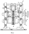
- is a perspective view of a two-stage, indexed, rotary punching assembly of the present invention showing three rows of punches and ejectors;
- Figure 2
- is an end elevation of the assembly shown in
Figure 1 illustrating cam roll followers and cam raceways; - Figure 3
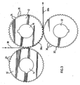
- is a side elevation of the rotary punching assembly of the invention;
- Figure 4
- is an enlarged side elevation of the assembly shown in
Figure 3 ; - Figure 5
- is an illustration of the relationship of the punching dies, separated from each other for clarity of illustration;
- Figure 6
- is an enlargement from
Figure 5 which illustrates the punch-out opening relationship of the dies in the first-stage operation; - Figure 7
- is an enlargement from
Figure 5 which illustrates the relationship of the dies and the punch-out opening in the second-stage operation; - Figure 8a, 8b and 8c
- illustrate the two-stage indexed rotary cutting sequence on a deformable strip;
- Figure 9
- is a side elevation view illustrating the roller cam assembly of the invention;
- Figure 10
- is a side elevation showing the cam raceway for receiving the ends of cam rollers shown in
Figure 9 ; and - Figure 11
- is an enlarged view of cam follower ejectors in a retracted position.
- With reference first to
Figures 1 - 8 andFigure 11 , the apparatus of the invention comprises a first pair of opposed dies 10, 12 mounted for synchronized rotation onshafts frame 18. As shown more clearly inFigures 3 and4 , die 10 is a female die keyed onshaft 14 and has transverse rows of angularlyequispaced recesses 20 formed on the periphery thereof.Die 12 is a male/female die keyed ondrive shaft 16 having transverse rows of angularly equispaced alternatingpunches 24 and recesses 26 formed on the periphery thereof.Punches 24 are adapted to mate with andfit recesses 20 ofdie 10. Eachpunch 24 has ashoulder 28 formed on each side thereof betweenpunch 24 andadjacent recess 26 for reasons which will become apparent as the description proceeds (Figure 11 ). Although three rows of punches and recesses are shown, it will be understood that one, two or more rows of punches and recesses can be used, depending on the requirements of the punched product. -
Die 30 mounted for rotation onshaft 32 is a male die keyed onshaft 32 for synchronized rotation with die 12 inframe 18. Male die 30 has angularly equispaced transverse rows ofpunches 36 adapted to mate with and fit in rows ofrecesses 26 ofdie 12 between punch shoulders 28. Although recesses and punches are shown equispaced, the recesses and punches can be spaced as desired for the final product, both angularly about the periphery of the dies and transversely across the width of the dies. - Dies 10, 12 and 30 are driven by
anti-lash gears shafts - During rotation of dies 10, 12 and 30,
strip 38 guided bystrip guide 19 between dies 10 and 12 is punched in a first stage by sequential insertion of transverse rows ofpunches 24 on die 12 into transverse rows of mating recesses 20 ondie 10. Punch-outmaterial 40 is discharged from female die 10 as shown inFigure 9 . Thestrip 38 is keyed onto male/female die12 by engagement ofstrip 38 between rows ofpunches 24 as die 12 rotates to feedstrip 38a between male/female die 12 and male die 30.Strip 38a is punched in a second stage, by insertion of rows ofpunches 36 of male die 30 into mating recesses 26 of male/female die 12 for displacement of punch-out material 42 intorecesses 26 between punch shoulders 28 with punchedstrip 38b discharged from the assembly. Punch-out material 42 is discharged from die 12 (Figure 9 ). - Referring now to the enlarged views of
Figures 4 ,6 ,7 and11 , punches 24 of male/female die 12 are adapted to be inserted into opposedrecesses 20 of female die 10 as the dies rotate. In like manner, punches 36 of male die 30 are adapted to be inserted into opposedrecesses 26 of male/female die 12 betweenshoulders 28 ofpunches 24 as the dies rotate. -
Figures 1 ,2 ,9 and 10 illustrate the cam roller assembly of the invention for ejecting punch-outs 40, 42 shown inFigure 9 . A plurality of equispacedtransverse roller rods 50 havingcaps 52 at each end fit loosely throughopenings 56 inside plates opposed cam raceways Figures 9 and 10 , each of a plurality ofangular segments 66 mounted in an annulus formed in proximity to the perimeter of each of dies 10, 12 continuously about the perimeter of the dies is adapted to receive arod 50 therethrough in snug-fitting relationship and is adapted for controlled radial travel in each ofcam raceways - Each
angular segment 66 has three angularly equispaced radial ejector pins 70 adapted to project through recesses 20. In operation,angular segments 66 of female die 10 are moved radially outwardly at the 6o'clock position 62a ofraceway 62 for segment 66a to eject punch-outs 40.Angular segments 66 of male/female die 12 are moved radially outwardly at the 3 o'clock position 64a ofraceway 64 for segments 66b to eject punch-outs 42. - Turning now to
Figures 8a - 8c, Figure 8b shows first-stage openings depicted by numeral 44 having a length A, width B + CC, wire width C1 betweenadjacent openings 44, and space D betweenopenings 44; andFigure 8c shows second-stage openings depicted by numeral 48 having a length A, width B, wire width C1 + CC laterally betweenadjacent openings 48, and wire width C2 longitudinally betweenopenings A = length of opening in direction of rotation B = width of opening transversely to direction of rotation C1 and C2 = wire width CC = cutter clearance D = distance between first-stage openings (C2 + A + C2) - In operation, turning now to
Figure 8b ,strip 38 has a first set of spaced-apart transverse rows ofholes 44 punched out during travel between dies 10 and 12, punch-outs 40 having a length A longitudinally in the process direction and a transverse width B + CC. C1 depicts the wire width in the process direction. A transverse space D between eachrow 44 of punched holes is punched between dies 12 and 30 as shown inFigure 8c to produce a second set of transverse rows ofholes 48 having a length A in the process direction and transverse width B. C2 depicts the transverse wire width, i.e. perpendicular to the process direction. - The accuracy and tolerance of the grid product is dependent upon the accuracy and tolerances of the machine itself. Material indexing is dependent upon gearing and the interaction between the three shafts and their tooling. It is therefore imperative that the gears and shafts be made to exact specifications. Improper meshing of the drive gears can result in too little clearance or interference on one side of the tooling. To cleanly shear deformable material such as lead and lead alloy, it is also important to have a very tight tolerance between male and female dies. The optimum clearance (CC) between cutting surfaces is quite strictly defined within the range of 0.0127 to 0.102 mm (0.0005 to 0.004 inch) preferably about 0.038 mm (0.0015 inch) between cutting edges. If the shearing edges are too far apart from each other, the material will not cut properly and partially-punched holes will result. If the shearing edges are too close to each other, the edges might catch and bind, which can result in the machine seizing. Since the tooling is made of hard and brittle D2 steel, the tooling may also chip or break if the machine seizes, resulting in costly repairs and shut down.
- A prototype module illustrated most clearly in
Figures 1, 2 and 9 - 11 was built to examine the viability of rotary hole punching. The machine utilized three rows of tooling to produce three transverse rows of punched holes in a given strip of lead alloy. For "Test 1", cast and rolled forms of both pure and alloyed lead were run through the machine. Punching of the closely spaced and high tolerance holes was 100% successful. - The wire width of a lead alloy grid produced was about 0.762 mm (0.030 inch) and approximately 85% of the strip material was removed as waste. Up to about 96% the strip material can be removed as waste, leaving a wire thickness as thin as 0.254 mm (0.010 inch). The thickness of strip material tested was about 0.762 mm (0.030 inch).
- Seven more tests were conducted with the rotary punching machine, to determine whether it was capable of performing the same accurate and precise operation for producing 0.762 mm (0.030 inch) wire width on various materials, other than lead, with the following material thicknesses: test 2, 0.178 mm (0.007 inch) and 0.381 mm (0.015 inch) aluminium;
test 3, 0.294 mm (0.010 inch) brass; test 4, 0.584 mm (0.023 inch) copper, test 5, 0.305 mm (0.012 inch) and 0.635 mm (0.025 inch) carboard; test 6 0.508 mm (0.020 inch) and 0.762 mm (0.030 inch) Mylar, test 7, 0.406 mm (0.016 inch) steel; test 8, 0.381 mm (0.015 inch), 0.406 mm (0.016 inch) and 0.635 mm (0.025 inch) zinc. There was no variation between the characteristics of these results and those obtained from punching lead strip. The holes were punched in a uniform manner with the same precision and no compromise to tolerances or mesh quality speed. Variation of the rotary speed of the rotary punch permitted a high operational speed for the precision hole puncher. - A punched strip of a thickness of about 0.762 mm (0.030 inch) having a plurality of longitudinally-spaced transverse rows of punched holes representing up to about 96% material removed, with a wire thickness as thin as 0.294 mm (0.010 inch), can be cut into battery plates of equal length. The plates are pasted and stacked vertically as negative plates alternating with positive plates separated from one another by plate separators in a plastic case with a cover. Grid tabs formed on the negative plates are interconnected by a metal header to a negative battery post and grid tabs formed on the positive plates are interconnected by a metal header to a positive battery post. Sulphuric acid solution is added in an amount to submerge the battery plates to form a lead acid battery.
- The present invention provides a number of important advantages. High-speed production of punched strip having an array of high tolerance, closely-spaced holes is permitted from deformable strip, particularly lead and lead-alloy strip. The success of the precision tolerancing is believed due to the self indexing system which makes use of the male dies 12 on
shaft 16. The male dies punch the strip material, which then stays seated on the die punches 24 ofdie 12 to act as the indexing mechanism for the strip. In this way, the strip material is anchored by the punched holes and the strip material is accurately positioned for the next sequence of holes to be punched without any compromise as to location Maximum hole size and hole spacing are practically limitless, depending only on customer requiremens. Hole shapes are also variable with substantially no geometric limitations. - It will be understood that other embodiments and examples of the invention will be readily apparent to a person skilled in the art, the scope and purview of the invention being defined in the appended claims.
Claims (27)
- A method of continuously punching an array of closely-spaced holes in a deformable strip (38) in a rotary punch which comprises feeding said deformable strip between a female rotary die (10) having a cylindrical periphery with a plurality of spaced recesses (20) formed on the cylindrical periphery and a male/female rotary die (12) having a cylindrical periphery with a plurality of alternating spaced punches (24) and recesses (26) formed on the cylindrical periphery for mating of said punches (24) of the male/female rotary die (12) with corresponding said recesses (20) of the female die (10), rotating said female and male/female dies (10, 12) concurrently for punching a first set of spaced holes (44) in the deformable strip along the deformable strip, feeding said punched deformable strip between said male/female rotary die (12) and a male rotary die (30) having a cylindrical periphery with a plurality of spaced punches (36) formed on the cylindrical perimeter for mating of said punches (36) of the male rotary die (30) with corresponding said recesses (26) of the male/female rotary die (12), and rotating said male/female die (12) concurrently with the male die (30) for punching a second set of holes (48) in the strip between the first set of spaced holes (44) along the deformable strip.
- A method as claimed in claim 1, continuously ejecting punched material (40, 42) from the female rotary die (10) and the male/female rotary die (12).
- A method as claimed in claim 2, in which the recesses (20) formed on the female rotary die (10), the alternating punches (24) and recesses (26) formed one the male/female rotary die (12), and the punches (36) formed on the male die (30) are variably spaced along the strip and/or across the strip, or staggered across the strip.
- A method as claimed in claim 2, in which the recesses (20) formed on the female rotary die (10), the alternating punches (24) and recesses (26) formed on the male/female rotary die (12), and the punches (36) formed on the male die (30) are equispaced.
- A method as claimed in claims 1 - 4 characterized by said first set of holes and second set of holes in the strip are punched transversely of the deformable strip.
- A method as claimed in claim 5, mounting a plurality of angular segments (66) continuously about an annulus formed in each of the cylindrical female die (10) and the cylindrical male/female die (12) in proximity to the perimeter of the respective cylindrical dies, each angular segment having at least one ejector pin (70) for radial reciprocal travel in a die recess (20, 26), and moving the angular segments (66) radially outwardly at a selected angle of rotation of the cylindrical female die (10) and of the cylindrical male/female die (12) for ejecting punch-out material (40, 42) from the die recesses (20, 26).
- A method as claimed in claim 6, providing a plurality of cam rollers (50) extending loosely across each of the cylindrical female die (10) and the cylindrical male/female die (12), each cam roller (50) passing through an angular segment (66) for moving said angular segment (66) radially inwardly and outwardly in the die annulus (62, 64) for reciprocal radial movement of a die ejector pin (70) in a die recess, and moving the cam rollers (50) and associated angular segments (66) outwardly at a selected angle of rotation of each of the dies (10, 12) whereby the angular segment ejector pins (70) eject punch-out material (40, 42) from the cylindrical dies (10, 12) at the selected angles of rotation.
- A method as claimed in claim 7, mounting opposite ends (52) of the cam rollers (50) in opposed stationary cam raceways (62a, 64a) formed on each side of each cylindrical die (10, 12) for controllably moving the cam rollers (50) radially inwardly and outwardly as the dies (10, 12) rotate.
- A methods as claimed in claim 8, in which the recesses (20) formed on the female rotary die (10), the alternating punches (24) and recesses (26) formed on the male/female rotary die (12), and the punches (36) formed on the male die (30) are variably spaced along the strip and/or across the strip, or staggered across the strip.
- A method as claimed in claim 8, in which the recess (20, 26) formed on the female rotary die (10) and on the male/female rotary die (12) are equispaced. '
- A method as claimed in claim 6, in which the deformable strip (38) is selected from the group of strips consisting of lead, lead alloys, aluminum, brass, copper, steel, zinc, plastics, vinyl and cardboard.
- A method as claimed in claim 6, in which the deformable strip (38) is lead or lead alloy.
- A method as claimed in claim 12, characterized by the strip having a plurality of longitudinally-spaced transverse rows of punched holes representing up to about 96% material removed with a residual wire thickness as thin as 0,254 mm (0.010 inch).
- An apparatus for continuously rotary punching an array of closely-spaced holes (44, 46) in a deformable strip (38) comprising a cylindrical female die (10) having a plurality of spaced recesses (20) formed about its periphery and mounted for rotation in a frame (18), a cylindrical male/female die (12) having a plurality of alternating spaced punches (24) and recesses (26) formed about its periphery and mounted for rotation in said frame (18) for mating the punches (24) of the male/female die (12) with corresponding recesses (20) in the female die (10), and a cylindrical male die (30) having a plurality of spaced punches (36) formed about its periphery mounted for rotation in said frame (18) for mating of the punches of the male die (36) with corresponding recesses (26) in the male/female die (12), whereby interaction of the punches (24) of the male/female die (12) with corresponding recesses (20) of the female die (10) and interaction of the punches (36) of the male die (30) with the recesses (26) of the male/female die (12) index the strip (38) with the female, male/female and male dies (10, 12, 30) during rotation.
- An apparatus as claimed in claim 14, in which said apparatus additionally comprises means for continuously ejecting punch-out material from the female die and from the male/female die during rotary punching of the deformable strip.
- An apparatus as claimed in claim 15, in which each of the punches (24) in the male/female die (12) has a shoulder (28) formed on each side of the punch (24) for supporting the deformable material and defining the recesses (26) for mating with the punches (36) in the male die (30).
- An apparatus as claimed in claim 16, in which the means for continuously ejecting punch-out material comprises a plurality of angular segments (66) mounted in an annulus (62, 64) formed in proximity to the perimeter of the dies (10, 12) continuously about the perimeter of the dies adapted for controlled radial travel of the angular segments (66) during rotation of the dies (10, 12), each angular segment (66) having at least one ejector pin (70) for radial reciprocal travel in a die recess (20, 26), whereby outward radial travel of the pin (70) ejects punch-out material from the recess.
- An apparatus as claimed in claim 17, in which each die (10, 12) has a plurality of spaced cam rollers (50) extending loosely across the die (10, 12) in the annulus (62, 64) in proximity to the die perimeter, each cam roller (50) passing through an angular segment (66) for moving said angular cam segment (66) radially inwardly and outwardly in the die (10, 12), and a pair of opposed stationary cam raceways (62a, 64a) mounted in the frame at each side of the die for receiving opposite ends (52) of the cam rollers (50) for controllably moving the cam rollers (50) radially inwardly and outwardly as the die rotates.
- An apparatus as claimed in claim 16, in which said cylindrical female die (10) comprises a plurality of discs assembled side-by-side, each disc having a plurality of the spaced recesses (20) formed about its periphery in lateral alignment across the die (10), said cylindrical male/female die (12) comprises a plurality of discs assembled side-by-side, each disc having a plurality of the alternating spaced punches (24) and recesses (26) formed about its periphery in lateral alignment across the male/female die (12) for mating of the punches (24) of the male/female die (12) in lateral alignment across the male/female die (12) with corresponding recesses (20) in the female die (10) in lateral alignment across the female die (10), and said cylindrical male die (30) comprises a plurality of discs assembled side-by-side, each disc having a plurality of the spaced punches (36) formed about its periphery in lateral alignment across the male die (30) for mating of the punches (36) of the male die (30) with the corresponding recesses (26) in the male/female die (12) in lateral alignment across the male/female die (12).
- An apparatus as claimed in claim 19, in which the spaced recesses (20) formed on the female die (10), the alternating punches (24) and recesses (26) formed on the male/female die (12), and the punches (36) formed on the male die (30) are variably spaced about the periphery of each of said dies (10, 12, 30).
- An apparatus as claimed in claim 19, in which the spaced recesses (20) formed on the female die (10), the alternating punches (24) and recesses (26) formed on the male/female die (12), and the punches (36) formed on the male die (30) are equispaced about the periphery of each of said dies (10, 12, 30).
- An apparatus as claimed in claim 19, in which the recesses (20) formed in the female die (10), the punches (24) and recesses (26) formed on the male/female die (12) and the punches (36) formed on the male die (30) are variably spaced and in lateral alignment across the dies (10, 12, 30).
- An apparatus as claimed in claim 19, in which the recesses (20) formed in the female die (10), the punches (24) and recesses (26) formed on the male/female die (12) and the punches (36) formed on the male die (30) are equispaced and in lateral alignment across the dies (10, 12, 30).
- An apparatus as claimed in claim 19, in which the spaced recesses (20) in the female die (10), the alternating punches (24) and recesses (26) formed on the male/female die (12) and the punches (36) formed on the male die (30) are variably spaced about the periphery of the dies (10, 12, 30) and in lateral alignment across the dies (10, 12, 30).
- An apparatus as claimed in claim 19, in which the spaced recesses (20) in the female die (10), the alternating punches (24) and recesses (26) formed on the male/female die (12) and the punches (36) formed on the male die (30) are equispaced about the periphery of the dies (10, 12, 30) and in lateral alignment across the dies (10, 12, 30).
- An apparatus as claimed in claim 19, in which in which the spaced recesses (20) in the female die (10), the alternating punches (24) and recesses (26) formed on the male/female die (12) and the punches (36) formed on the male die (30) are variably spaced about the periphery of the dies (10, 12, 30) and staggered across the dies (10, 12, 30).
- An apparatus as claimed in claim 19, in which in which the spaced recesses (20) in the female die (10), the alternating punches (24) and recesses (26) formed on the male/female die (12) and the punches (36) formed on the male die (30) are equispaced about the periphery of the dies (10, 12, 30) and staggered across the dies (10, 12, 30).
Applications Claiming Priority (2)
| Application Number | Priority Date | Filing Date | Title |
|---|---|---|---|
| US10/799,718 US7066066B2 (en) | 2004-03-15 | 2004-03-15 | Continuous rotary hole punching method and apparatus |
| PCT/CA2005/000231 WO2005087454A1 (en) | 2004-03-15 | 2005-02-21 | Continuous rotary hole punching method and apparatus |
Publications (3)
| Publication Number | Publication Date |
|---|---|
| EP1727654A1 EP1727654A1 (en) | 2006-12-06 |
| EP1727654A4 EP1727654A4 (en) | 2007-05-09 |
| EP1727654B1 true EP1727654B1 (en) | 2009-05-06 |
Family
ID=34920561
Family Applications (1)
| Application Number | Title | Priority Date | Filing Date |
|---|---|---|---|
| EP20050706497 Expired - Lifetime EP1727654B1 (en) | 2004-03-15 | 2005-02-21 | Continuous rotary hole punching method and apparatus |
Country Status (11)
| Country | Link |
|---|---|
| US (2) | US7066066B2 (en) |
| EP (1) | EP1727654B1 (en) |
| JP (1) | JP2007529324A (en) |
| KR (1) | KR20060127177A (en) |
| CN (1) | CN1929975A (en) |
| AT (1) | ATE430647T1 (en) |
| BR (1) | BRPI0508270A (en) |
| CA (1) | CA2552039C (en) |
| DE (1) | DE602005014346D1 (en) |
| RU (1) | RU2006131589A (en) |
| WO (1) | WO2005087454A1 (en) |
Families Citing this family (16)
| Publication number | Priority date | Publication date | Assignee | Title |
|---|---|---|---|---|
| ITVR20040173A1 (en) * | 2004-11-05 | 2005-02-05 | Sovema Spa | EQUIPMENT FOR THE FORMATION OF CONTINUOUS METAL GRILLS, IN PARTICULAR THE REALIZATION OF GRILLS FOR ELECTRIC ACCUMULATORS |
| US20070000365A1 (en) * | 2005-06-29 | 2007-01-04 | Edwin Hirahara | Method for digital die cutter for containerboard packaging |
| ATE467916T1 (en) * | 2006-02-22 | 2010-05-15 | Teck Metals Ltd | METHOD AND DEVICE FOR THE CONTINUOUS PRODUCTION OF BATTERY NETWORKS |
| DE102006017939A1 (en) * | 2006-04-11 | 2007-10-25 | Decoma (Germany) Gmbh | Method for punching workpieces |
| DK2024149T3 (en) * | 2006-05-11 | 2012-04-30 | Maerdian Werkzeug Und Maschb Gmbh | Apparatus for rotary punching of die cutters with defined geometry and size of a planar structure and its use |
| KR101004214B1 (en) | 2007-04-03 | 2010-12-24 | 심재헌 | Nonwoven fabric drilling apparatus and method thereof, nonwoven fabric formed thereby |
| CN101569905B (en) * | 2009-06-01 | 2011-05-25 | 北方工业大学 | Rotary punching device |
| IT1402081B1 (en) | 2010-09-22 | 2013-08-28 | Sovema Spa | GRID FORMING MACHINE FOR THE CONSTRUCTION OF ELECTRIC STORAGE PLATES. |
| JP5866712B2 (en) * | 2012-07-03 | 2016-02-17 | トヨタ車体株式会社 | Roll forming equipment |
| CN105171806B (en) * | 2015-08-20 | 2017-04-05 | 新乡市豫新风电设备工程有限公司 | A kind of plate material cutting mechanism |
| US20170084926A1 (en) | 2015-09-18 | 2017-03-23 | Mitek Holdings, Inc. | Battery grid and method of making |
| CN115249816A (en) * | 2021-06-17 | 2022-10-28 | 浙江天能电池(江苏)有限公司 | Lead-acid storage battery grid mesh belt forming device |
| CN113290127B (en) * | 2021-07-05 | 2022-05-31 | 荆梅 | Multi-station continuous punching machine for machining machine parts |
| CN113815261A (en) * | 2021-09-13 | 2021-12-21 | 方友良 | Corrugated board production and processing method |
| CN115318948B (en) * | 2022-07-27 | 2025-06-03 | 中机精冲科技(福建)有限公司 | A processing technology and production line for special-shaped large-size precision blanking parts |
| CN117772909A (en) * | 2023-12-29 | 2024-03-29 | 江苏伟武电气设备有限公司 | Strip continuous punching process system for trough bridge production |
Family Cites Families (20)
| Publication number | Priority date | Publication date | Assignee | Title |
|---|---|---|---|---|
| GB920442A (en) | 1958-05-06 | 1963-03-06 | British Rayon Res Ass | Embossing of fabrics |
| GB920443A (en) * | 1958-10-14 | 1963-03-06 | Austen Robert Higgin | Improvements relating to the punching of metal members such as sheets, joists or the like |
| DE2029863C3 (en) * | 1970-06-18 | 1973-10-25 | Maschinenfabrik Goebel Gmbh, 6100 Darmstadt | Perforating unit for simultaneous longitudinal and transverse perforation of sheets or webs |
| GB1402200A (en) * | 1973-04-02 | 1975-08-06 | Ici Ltd | Sheet cutter |
| US4074599A (en) * | 1976-07-14 | 1978-02-21 | Wood Industries, Inc. | Paper web perforating machine |
| JPS5439287A (en) * | 1977-09-02 | 1979-03-26 | Furukawa Electric Co Ltd:The | Method of press-punching lead and lead alloy |
| SE442964B (en) * | 1982-12-01 | 1986-02-10 | Tetra Pak Int | VIEW TO REMOVE GAMING MATERIAL AT CUTTING CONTROL WITH CONNECTING ROLLS |
| US4561334A (en) * | 1984-06-19 | 1985-12-31 | Bernal Rotary Systems, Inc. | Rotary stripper |
| DE3637110C1 (en) * | 1986-10-31 | 1988-05-19 | Heidelberger Druckmasch Ag | Device for cutting and dividing a continuous flow of printed products |
| DE9017365U1 (en) * | 1990-12-22 | 1992-01-30 | Westaflexwerk GmbH & Co KG, 4830 Gütersloh | Device for punching strips made of foil or sheet metal |
| US5140880A (en) * | 1991-05-08 | 1992-08-25 | Littleton Industrial Consultants, Inc. | Push-pull apparatus and method for web cutting and trim strip removal |
| DE4130673A1 (en) * | 1991-09-14 | 1993-03-18 | Schuler Gmbh L | Press to perforate and corrugate material strip - has advance rollers, with adjustable rotary positions, to place perforations relative to corrugations |
| US5363728A (en) * | 1992-10-22 | 1994-11-15 | Elsner Engineering Works, Inc. | Two roll web cutter and method |
| BE1006751A3 (en) * | 1993-02-17 | 1994-11-29 | Mach Service N V Naamloze Venn | Method for perforating FOIL AND device which applies this method. |
| DE4319300A1 (en) * | 1993-06-10 | 1994-12-22 | Baust Werkzeugtechnik Gmbh | Method for the production of sheet-metal parts provided with punched-out tabs |
| US6167601B1 (en) * | 1995-09-22 | 2001-01-02 | Conrad American | Method for manufacturing ventilated sheet-metal floor members |
| US5937719A (en) * | 1996-06-27 | 1999-08-17 | Wilson Manufacturing Company | Rotary punch |
| US5811641A (en) * | 1996-10-04 | 1998-09-22 | Holden's Foundation Seeds Inc. | Inbred corn line LH179 |
| CA2288561C (en) | 1999-11-05 | 2006-10-24 | Michael Surina | Rotary punching apparatus |
| JP4783977B2 (en) * | 2000-12-07 | 2011-09-28 | 株式会社Gsユアサ | Lead acid battery |
-
2004
- 2004-03-15 US US10/799,718 patent/US7066066B2/en not_active Expired - Lifetime
-
2005
- 2005-02-21 KR KR1020067018545A patent/KR20060127177A/en not_active Abandoned
- 2005-02-21 CA CA002552039A patent/CA2552039C/en not_active Expired - Lifetime
- 2005-02-21 AT AT05706497T patent/ATE430647T1/en not_active IP Right Cessation
- 2005-02-21 EP EP20050706497 patent/EP1727654B1/en not_active Expired - Lifetime
- 2005-02-21 DE DE200560014346 patent/DE602005014346D1/en not_active Expired - Fee Related
- 2005-02-21 WO PCT/CA2005/000231 patent/WO2005087454A1/en not_active Ceased
- 2005-02-21 BR BRPI0508270-6A patent/BRPI0508270A/en not_active IP Right Cessation
- 2005-02-21 CN CNA2005800074127A patent/CN1929975A/en active Pending
- 2005-02-21 RU RU2006131589/02A patent/RU2006131589A/en unknown
- 2005-02-21 JP JP2007503157A patent/JP2007529324A/en active Pending
-
2006
- 2006-05-10 US US11/430,826 patent/US7380484B2/en not_active Expired - Lifetime
Also Published As
| Publication number | Publication date |
|---|---|
| US20050199110A1 (en) | 2005-09-15 |
| US7380484B2 (en) | 2008-06-03 |
| WO2005087454A1 (en) | 2005-09-22 |
| DE602005014346D1 (en) | 2009-06-18 |
| RU2006131589A (en) | 2008-03-10 |
| CN1929975A (en) | 2007-03-14 |
| KR20060127177A (en) | 2006-12-11 |
| BRPI0508270A (en) | 2007-07-31 |
| ATE430647T1 (en) | 2009-05-15 |
| EP1727654A1 (en) | 2006-12-06 |
| EP1727654A4 (en) | 2007-05-09 |
| US7066066B2 (en) | 2006-06-27 |
| CA2552039C (en) | 2008-10-28 |
| US20060201294A1 (en) | 2006-09-14 |
| CA2552039A1 (en) | 2005-09-22 |
| JP2007529324A (en) | 2007-10-25 |
Similar Documents
| Publication | Publication Date | Title |
|---|---|---|
| US7380484B2 (en) | Continuous rotary hole punching method and apparatus | |
| EP1994589B1 (en) | Method and apparatus for continuous manufacture of battery grids | |
| US20100122563A1 (en) | Method and apparatus for forming bend-controlling straps in sheet material | |
| EP0779670A1 (en) | Perforated substrate and method of manufacture | |
| CN109170078B (en) | A candy forming machine | |
| WO2005105335A1 (en) | Apparatus and method for forming shaped articles | |
| CN101222166A (en) | Motor Stator and Rotor Punching Method | |
| CN112792207B (en) | Methods to prevent material from breaking and bending | |
| KR20050092043A (en) | Method and apparatus for in-situ leveling of progressively formed sheet metal | |
| WO2007050995A1 (en) | Apparatus for scrap removal from rotary cutting tool | |
| CN102350455A (en) | Method for manufacturing moving blade of multi-head rotary electric shaver | |
| CN111250598B (en) | Paper shredder blade stamping die | |
| DE102013018995B4 (en) | Plant for the rotary cutting of electrical sheets | |
| CN209439513U (en) | A die-cutting device used on a pilot test line for battery pole pieces | |
| US3381514A (en) | Method and apparatus for making toothed lock washers | |
| MXPA06009263A (en) | Continuous rotary hole punching method and apparatus | |
| CN211758133U (en) | Circular scattered flaky workpiece collecting die | |
| CN104416043A (en) | Multi-hole punching crushed-aggregate-free forming method for saw web | |
| CN216027541U (en) | Stamping device for stamping and discharging aerosol can cover | |
| CN222242242U (en) | A continuous die for servo motor stamping parts | |
| SU1547922A1 (en) | Method of progressive forming and die set for effecting same | |
| CN210614788U (en) | Exhaust blanking mould | |
| CN209902025U (en) | Blanking die | |
| CN121402488A (en) | Method and press for introducing deformed patterns in a sheet | |
| JP3089716U (en) | ID blade forming mold |
Legal Events
| Date | Code | Title | Description |
|---|---|---|---|
| PUAI | Public reference made under article 153(3) epc to a published international application that has entered the european phase |
Free format text: ORIGINAL CODE: 0009012 |
|
| 17P | Request for examination filed |
Effective date: 20061016 |
|
| AK | Designated contracting states |
Kind code of ref document: A1 Designated state(s): AT BE BG CH CY CZ DE DK EE ES FI FR GB GR HU IE IS IT LI LT LU MC NL PL PT RO SE SI SK TR |
|
| A4 | Supplementary search report drawn up and despatched |
Effective date: 20070405 |
|
| RIC1 | Information provided on ipc code assigned before grant |
Ipc: B26D 1/24 20060101AFI20050928BHEP Ipc: B21D 28/36 20060101ALI20070330BHEP |
|
| TPAC | Observations filed by third parties |
Free format text: ORIGINAL CODE: EPIDOSNTIPA |
|
| DAX | Request for extension of the european patent (deleted) | ||
| 17Q | First examination report despatched |
Effective date: 20080218 |
|
| GRAP | Despatch of communication of intention to grant a patent |
Free format text: ORIGINAL CODE: EPIDOSNIGR1 |
|
| GRAS | Grant fee paid |
Free format text: ORIGINAL CODE: EPIDOSNIGR3 |
|
| RAP1 | Party data changed (applicant data changed or rights of an application transferred) |
Owner name: TECK COMINCO METALS LTD. |
|
| GRAA | (expected) grant |
Free format text: ORIGINAL CODE: 0009210 |
|
| AK | Designated contracting states |
Kind code of ref document: B1 Designated state(s): AT BE BG CH CY CZ DE DK EE ES FI FR GB GR HU IE IS IT LI LT LU MC NL PL PT RO SE SI SK TR |
|
| REG | Reference to a national code |
Ref country code: GB Ref legal event code: FG4D |
|
| REG | Reference to a national code |
Ref country code: CH Ref legal event code: EP |
|
| REG | Reference to a national code |
Ref country code: IE Ref legal event code: FG4D |
|
| REF | Corresponds to: |
Ref document number: 602005014346 Country of ref document: DE Date of ref document: 20090618 Kind code of ref document: P |
|
| PG25 | Lapsed in a contracting state [announced via postgrant information from national office to epo] |
Ref country code: PT Free format text: LAPSE BECAUSE OF FAILURE TO SUBMIT A TRANSLATION OF THE DESCRIPTION OR TO PAY THE FEE WITHIN THE PRESCRIBED TIME-LIMIT Effective date: 20090906 Ref country code: FI Free format text: LAPSE BECAUSE OF FAILURE TO SUBMIT A TRANSLATION OF THE DESCRIPTION OR TO PAY THE FEE WITHIN THE PRESCRIBED TIME-LIMIT Effective date: 20090506 Ref country code: LT Free format text: LAPSE BECAUSE OF FAILURE TO SUBMIT A TRANSLATION OF THE DESCRIPTION OR TO PAY THE FEE WITHIN THE PRESCRIBED TIME-LIMIT Effective date: 20090506 Ref country code: AT Free format text: LAPSE BECAUSE OF FAILURE TO SUBMIT A TRANSLATION OF THE DESCRIPTION OR TO PAY THE FEE WITHIN THE PRESCRIBED TIME-LIMIT Effective date: 20090506 Ref country code: ES Free format text: LAPSE BECAUSE OF FAILURE TO SUBMIT A TRANSLATION OF THE DESCRIPTION OR TO PAY THE FEE WITHIN THE PRESCRIBED TIME-LIMIT Effective date: 20090817 |
|
| NLV1 | Nl: lapsed or annulled due to failure to fulfill the requirements of art. 29p and 29m of the patents act | ||
| PG25 | Lapsed in a contracting state [announced via postgrant information from national office to epo] |
Ref country code: SE Free format text: LAPSE BECAUSE OF FAILURE TO SUBMIT A TRANSLATION OF THE DESCRIPTION OR TO PAY THE FEE WITHIN THE PRESCRIBED TIME-LIMIT Effective date: 20090806 Ref country code: SI Free format text: LAPSE BECAUSE OF FAILURE TO SUBMIT A TRANSLATION OF THE DESCRIPTION OR TO PAY THE FEE WITHIN THE PRESCRIBED TIME-LIMIT Effective date: 20090506 Ref country code: PL Free format text: LAPSE BECAUSE OF FAILURE TO SUBMIT A TRANSLATION OF THE DESCRIPTION OR TO PAY THE FEE WITHIN THE PRESCRIBED TIME-LIMIT Effective date: 20090506 Ref country code: NL Free format text: LAPSE BECAUSE OF FAILURE TO SUBMIT A TRANSLATION OF THE DESCRIPTION OR TO PAY THE FEE WITHIN THE PRESCRIBED TIME-LIMIT Effective date: 20090506 Ref country code: IS Free format text: LAPSE BECAUSE OF FAILURE TO SUBMIT A TRANSLATION OF THE DESCRIPTION OR TO PAY THE FEE WITHIN THE PRESCRIBED TIME-LIMIT Effective date: 20090906 |
|
| PG25 | Lapsed in a contracting state [announced via postgrant information from national office to epo] |
Ref country code: EE Free format text: LAPSE BECAUSE OF FAILURE TO SUBMIT A TRANSLATION OF THE DESCRIPTION OR TO PAY THE FEE WITHIN THE PRESCRIBED TIME-LIMIT Effective date: 20090506 Ref country code: DK Free format text: LAPSE BECAUSE OF FAILURE TO SUBMIT A TRANSLATION OF THE DESCRIPTION OR TO PAY THE FEE WITHIN THE PRESCRIBED TIME-LIMIT Effective date: 20090506 Ref country code: RO Free format text: LAPSE BECAUSE OF FAILURE TO SUBMIT A TRANSLATION OF THE DESCRIPTION OR TO PAY THE FEE WITHIN THE PRESCRIBED TIME-LIMIT Effective date: 20090506 Ref country code: CZ Free format text: LAPSE BECAUSE OF FAILURE TO SUBMIT A TRANSLATION OF THE DESCRIPTION OR TO PAY THE FEE WITHIN THE PRESCRIBED TIME-LIMIT Effective date: 20090506 |
|
| PG25 | Lapsed in a contracting state [announced via postgrant information from national office to epo] |
Ref country code: SK Free format text: LAPSE BECAUSE OF FAILURE TO SUBMIT A TRANSLATION OF THE DESCRIPTION OR TO PAY THE FEE WITHIN THE PRESCRIBED TIME-LIMIT Effective date: 20090506 Ref country code: BE Free format text: LAPSE BECAUSE OF FAILURE TO SUBMIT A TRANSLATION OF THE DESCRIPTION OR TO PAY THE FEE WITHIN THE PRESCRIBED TIME-LIMIT Effective date: 20090506 |
|
| PLBE | No opposition filed within time limit |
Free format text: ORIGINAL CODE: 0009261 |
|
| STAA | Information on the status of an ep patent application or granted ep patent |
Free format text: STATUS: NO OPPOSITION FILED WITHIN TIME LIMIT |
|
| PG25 | Lapsed in a contracting state [announced via postgrant information from national office to epo] |
Ref country code: BG Free format text: LAPSE BECAUSE OF FAILURE TO SUBMIT A TRANSLATION OF THE DESCRIPTION OR TO PAY THE FEE WITHIN THE PRESCRIBED TIME-LIMIT Effective date: 20090806 |
|
| 26N | No opposition filed |
Effective date: 20100209 |
|
| REG | Reference to a national code |
Ref country code: CH Ref legal event code: PL |
|
| GBPC | Gb: european patent ceased through non-payment of renewal fee |
Effective date: 20100221 |
|
| PG25 | Lapsed in a contracting state [announced via postgrant information from national office to epo] |
Ref country code: GR Free format text: LAPSE BECAUSE OF FAILURE TO SUBMIT A TRANSLATION OF THE DESCRIPTION OR TO PAY THE FEE WITHIN THE PRESCRIBED TIME-LIMIT Effective date: 20090807 Ref country code: MC Free format text: LAPSE BECAUSE OF NON-PAYMENT OF DUE FEES Effective date: 20100301 Ref country code: LI Free format text: LAPSE BECAUSE OF NON-PAYMENT OF DUE FEES Effective date: 20100228 Ref country code: CH Free format text: LAPSE BECAUSE OF NON-PAYMENT OF DUE FEES Effective date: 20100228 |
|
| REG | Reference to a national code |
Ref country code: FR Ref legal event code: ST Effective date: 20101029 |
|
| REG | Reference to a national code |
Ref country code: IE Ref legal event code: MM4A |
|
| PG25 | Lapsed in a contracting state [announced via postgrant information from national office to epo] |
Ref country code: IE Free format text: LAPSE BECAUSE OF NON-PAYMENT OF DUE FEES Effective date: 20100221 Ref country code: FR Free format text: LAPSE BECAUSE OF NON-PAYMENT OF DUE FEES Effective date: 20100301 |
|
| PG25 | Lapsed in a contracting state [announced via postgrant information from national office to epo] |
Ref country code: DE Free format text: LAPSE BECAUSE OF NON-PAYMENT OF DUE FEES Effective date: 20100901 |
|
| PG25 | Lapsed in a contracting state [announced via postgrant information from national office to epo] |
Ref country code: GB Free format text: LAPSE BECAUSE OF NON-PAYMENT OF DUE FEES Effective date: 20100221 Ref country code: IT Free format text: LAPSE BECAUSE OF NON-PAYMENT OF DUE FEES Effective date: 20100221 |
|
| PG25 | Lapsed in a contracting state [announced via postgrant information from national office to epo] |
Ref country code: CY Free format text: LAPSE BECAUSE OF FAILURE TO SUBMIT A TRANSLATION OF THE DESCRIPTION OR TO PAY THE FEE WITHIN THE PRESCRIBED TIME-LIMIT Effective date: 20090506 |
|
| PG25 | Lapsed in a contracting state [announced via postgrant information from national office to epo] |
Ref country code: LU Free format text: LAPSE BECAUSE OF NON-PAYMENT OF DUE FEES Effective date: 20100221 Ref country code: HU Free format text: LAPSE BECAUSE OF FAILURE TO SUBMIT A TRANSLATION OF THE DESCRIPTION OR TO PAY THE FEE WITHIN THE PRESCRIBED TIME-LIMIT Effective date: 20091107 |
|
| PG25 | Lapsed in a contracting state [announced via postgrant information from national office to epo] |
Ref country code: TR Free format text: LAPSE BECAUSE OF FAILURE TO SUBMIT A TRANSLATION OF THE DESCRIPTION OR TO PAY THE FEE WITHIN THE PRESCRIBED TIME-LIMIT Effective date: 20090506 |