EP1727295A1 - Voice speaking device - Google Patents
Voice speaking device Download PDFInfo
- Publication number
- EP1727295A1 EP1727295A1 EP04721712A EP04721712A EP1727295A1 EP 1727295 A1 EP1727295 A1 EP 1727295A1 EP 04721712 A EP04721712 A EP 04721712A EP 04721712 A EP04721712 A EP 04721712A EP 1727295 A1 EP1727295 A1 EP 1727295A1
- Authority
- EP
- European Patent Office
- Prior art keywords
- adjustment amount
- volume
- adjusting means
- reproduction
- communication device
- Prior art date
- Legal status (The legal status is an assumption and is not a legal conclusion. Google has not performed a legal analysis and makes no representation as to the accuracy of the status listed.)
- Withdrawn
Links
Images





Classifications
-
- H—ELECTRICITY
- H04—ELECTRIC COMMUNICATION TECHNIQUE
- H04M—TELEPHONIC COMMUNICATION
- H04M9/00—Arrangements for interconnection not involving centralised switching
- H04M9/08—Two-way loud-speaking telephone systems with means for conditioning the signal, e.g. for suppressing echoes for one or both directions of traffic
- H04M9/082—Two-way loud-speaking telephone systems with means for conditioning the signal, e.g. for suppressing echoes for one or both directions of traffic using echo cancellers
-
- H—ELECTRICITY
- H04—ELECTRIC COMMUNICATION TECHNIQUE
- H04M—TELEPHONIC COMMUNICATION
- H04M1/00—Substation equipment, e.g. for use by subscribers
- H04M1/60—Substation equipment, e.g. for use by subscribers including speech amplifiers
Definitions
- the present invention relates to a voice communication device, and in particular to a voice communication (call) device used for a voice communication system such as a mobile telephone, an IP telephone, and an audio conference system.
- a voice communication (call) device used for a voice communication system such as a mobile telephone, an IP telephone, and an audio conference system.
- Fig.7 shows a prior art arrangement of a voice communication device used for an IP telephone or the like.
- This arrangement is provided with a reproduction volume adjusting means (amplifier) 2 and a recording volume adjusting means (amplifier) 5 for manually adjusting respective volumes of a speaker 3 as a reproducing means and a microphone 4 as a recording means.
- a voice signal r(n), where "n" indicates a time, received from the opponent is transmitted to a talker 300 as an output sound V1 from the speaker 3.
- a voice V2 of the talker 300 is recorded by the microphone 4 to be transmitted to the opponent as a transmitting signal s(n).
- the voice of the opponent outputted from the speaker 3 is also recorded by the microphone 4 through an echo path to be transmitted to the opponent as an echo E. As a result, it becomes hard for the opponent to listen to the voice of the talker 300.
- a signal processing means 1 for removing or suppressing such an echo is provided.
- the signal processing means 1 has been generally well known as an echo canceller.
- the reproduction volume adjusting means 2 is for manually adjusting a level of a speaker signal spe(n) when the speaker signal spe(n) to the speaker 3 is small. If the reproduction volume adjusting means 2 is adjusted at this time so that the reproduction volume from the speaker 3 may become large, the echo E becomes large concurrently. On the other hand, if the reproduction volume from the speaker 3 is made small, the echo E becomes small concurrently. Namely, if the talker 300 changes a set value of the reproduction volume, the echo path also changes as the set value is changed.
- the signal processing means 1 with an echo canceller technology use an adaptive signal processing technology such as represented by a learning identification method.
- an adaptive signal processing technology such as represented by a learning identification method.
- an ERL (Echo Return Loss) measuring means 21 is additionally provided to the prior art example shown in Fig.7.
- This ERL measuring means 21 is for suppressing the above-mentioned residual echo by adjusting the recording volume adjusting means 5 based on a volume difference between the received signal r(n) (also corresponding to an output signal of the signal processing means 1) and a microphone signal mic(n) from the microphone 4.
- a reproduction volume adjustment amount (level of the speaker signal spe(n)) by the reproduction volume adjusting means 2 is increased by e.g. 6dB in the above-mentioned Eq.(1), the 1st term of the right-hand side in Eq.(1) is constant.
- the speaker signal spe(n) is provided to the speaker 3 to be hereby reproduced
- the signal level is increased by 6dB similarly, so that the level of the echo E recorded by the microphone 4 (the 2nd term of the right-hand side in Eq.(1)) is also increased by 6dB.
- the ERL(n) given by Eq.(1) is to be decreased by the increase amount of the 2nd term of the right-hand side, i.e. 6dB.
- the ERL measuring means 21 shown in Fig.8 measures the ERL(n) based on the above-mentioned Eq.(1), and controls the volume of the input signal to the signal processing means 1, i.e. the volume of the transmitting signal s(n) to the opponent, by the recording volume adjusting means 5 according to the change. Namely, in case of the above-mentioned example, the ERL measuring means 21 detects that the ERL(n) is decreased by 6dB, and controls so that the recording volume in the recording volume adjusting means 5 is decreased by 6dB.
- a voice communication device comprises: a first adjusting means adjusting a volume of a received signal; a second adjusting means adjusting a volume of a transmitting signal including the received signal having passed through an echo path; and a control means controlling an adjustment amount by the second adjusting means based on an adjustment amount by the first adjusting means.
- the first adjusting means corresponds to a reproduction volume adjusting means 2 adjusting a reproduction volume of a reproduction means 3.
- the second adjusting means corresponds to a recording volume adjusting means 5 adjusting a recording volume of a recording means 4.
- a control means corresponds to a control means 6 controlling a recording volume adjustment amount for the recording volume adjusting means 5 based on the reproduction volume adjustment amount for the reproduction volume adjusting means 2.
- a voice r(n) of the opponent outputted from a signal processing means 1 its volume is adjusted by the reproduction volume adjusting means 2 to be outputted from the reproduction means 3.
- a reproduction volume adjustment amount ⁇ (n) for the reproduction volume adjusting means 2 is provided by the control means 6. It is to be noted that the reproduction volume adjustment amount ⁇ (n) in this case may be inputted from e.g. an interface by the talker. Alternatively, a reproduction volume set value X automatically calculated from the volume of the received signal r(n) may be used or may be preliminarily stored in the control means 6.
- a recording volume adjustment amount ⁇ (n) for the recording volume adjusting means 5 is determined based on the reproduction volume adjustment amount ⁇ (n) by the control means 6.
- the residual echo components in an input signal in(n) to the signal processing means 1 depend on the volume adjustment amount ⁇ (n) [dB] for the reproduction volume adjusting means 2, the volume adjustment amount ⁇ (n) [dB] for the recording volume adjusting means 5, and a fixed acoustic coupling amount ERL 0 [dB] between the speaker 3 and the microphone 4.
- the reproduction volume adjustment amount ⁇ (n) in the reproduction volume adjusting means 2 is rapidly changed, the ERL(n) in the signal processing means 1 does not change. Accordingly, it becomes possible to adjust the volume so that the ERL(n) may become fixed without being measured.
- the volume adjustment amount is expressed by "dB”
- the received signal is actually multiplied by gain_ ⁇ (n) [times] by the reproduction volume adjusting means 2 to be reproduced from the speaker.
- the recorded signal is multiplied by gain_ ⁇ (n) [times] by the recording volume adjusting means 5 to be received by the signal processing means 1.
- a change amount D of the gain_ ⁇ (n) is controlled so as to be equal to an inverse number of a change amount C of the gain_ ⁇ (n).
- the change amount D of the gain_ ⁇ (n) may be controlled in inverse proportion as the following equation, instead of Eq.(4-7) or based on the inverse number.
- control means 6 may determine the reproduction volume adjustment amount ⁇ (n) [dB] based on the reproduction volume set value X.
- the control means 6 may determine the transmission volume adjustment amount for the transmission volume adjusting means based on the above-mentioned reproduction volume adjustment amount ⁇ (n) [dB]. In this case, it is possible to control the transmission volume adjustment amount based on the inverse number of the recording volume adjustment amount or in inverse proportion to the recording volume adjustment amount, namely so as to be equal to the reproduction volume adjustment amount. Thus, the input signal in(n) [dB] reduced by the recording volume adjusting means 5 can be compensated.
- control means 6 may determine the above-mentioned transmission volume adjustment amount.
- each of the above-mentioned adjusting means may comprise either a digital amplifier or an analog amplifier.
- Fig.2 shows a system arrangement where a voice communication device according to the present invention is incorporated.
- a handsfree function of an IP telephone software in a personal computer is incorporated into the voice communication device according to the present invention in a mobile telephone 100 connected to a public network 200.
- the mobile telephone 100 is provided with a voice communication device 103 receiving a received signal r(n) obtained through a decoder 102 which decodes a digital signal from a receiver 101 receiving an analog signal from the public network 200 to be converted into the digital signal, into the original code.
- This voice communication device 103 is for transmitting a transmitting signal s(n) encoded by the encoder 104 to the public network 200 after the signal is converted from the digital signal into the analog signal by a transmitter 105.
- An output sound V1 of the voice communication device 103 is provided to a talker 300 and a talker voice V2 from the talker 300 is received by the voice communication device 103.
- Fig.3 shows an arrangement of the above-mentioned voice communication device 103 in Fig.2 as well as an embodiment of the voice communication device shown in Fig.1.
- an echo canceller (EC) is used as the signal processing means 1, and volume adjusting amplifiers are respectively used as the volume adjusting means 2 and 5.
- a transmission volume adjusting amplifier (digital amplifier) 7 is used on the output side of the echo canceller 1.
- a D/A converter 9 is provided between the reproduction volume adjusting amplifier (digital amplifier) 2 and the speaker (reproduction means) 3
- an A/D converter 10 is provided between the microphone (recording means) 4 and the recording volume adjusting amplifier (digital amplifier) 5.
- a reproduction volume setting portion 8 is connected to the controller 6 as the control means.
- the controller 6 provides the reproduction volume adjustment amount ⁇ (n) [dB] to the reproduction volume adjusting amplifier 2 based on the reproduction volume set value X from the reproduction volume setting portion 8, for example, the received signal r(n) is amplified by ⁇ [dB] to assume the speaker signal spe(n).
- the speaker signal spe(n) is converted from the digital signal into the analog signal at the D/A converter 9 to be transmitted to the speaker 3.
- the recording analog signal from the microphone 4 is converted into the digital signal mic(n) at the A/D converter 10 to be provided to the recording volume adjusting amplifier 5.
- the recording volume adjustment amount ⁇ (n) [dB] is provided from the controller 6, so that the input of the recording volume adjusting amplifier 5 is amplified by the recording volume adjustment amount ⁇ (n) [dB] to be provided to the echo canceller 1 as the input signal in(n).
- an output signal out(n) from the echo canceller 1 is transmitted to the transmission volume adjusting amplifier 7, to which a transmission volume adjustment amount ⁇ [dB] is provided from the controller 6. Therefore, the output signal out(n) is amplified by the transmission volume adjustment amount ⁇ (n) [dB], so that the transmitting signal s(n) is outputted to the opponent.
- the talker 300 can select the reproduction volume set value during communication from among 5 stages (1-5).
- the initial value is set to "3".
- the controller 6 transmits the reproduction volume adjustment amount ⁇ (n) [dB] corresponding to the reproduction volume set value X to the reproduction volume adjusting amplifier 2.
- reproduction volume set value X The relationship between the reproduction volume set value X and the reproduction volume adjustment amount ⁇ (n) [dB] is indicated in the following table: TABLE 2 RELATIONSHIP BETWEEN REPRODUCTION VOLUME SETTING AND REPRODUCTION VOLUME ADJUSTMENT AMOUNT REPRODUCTION VOLUME SET VALUE X REPRODUCTION VOLUME ADJUSTMENT AMOUNT ⁇ (n)[dB] 5 +12 4 +6 3 0 2 -6 1 -12
- the ERL(n) is stabilized, and the operation of the echo canceller 1 is stably held, so that a good handsfree communication can be realized.
- Fig.6 shows an embodiment (2) that is a modification of the embodiment shown in Fig.3.
- the embodiment (2) is provided with a transmission volume setting portion 11 for setting a transmission volume set value Y in addition to the reproduction volume setting portion 8 for setting the set value X.
- the D/A converter 9 is provided between the reproduction volume adjusting amplifier (digital amplifier) 2 and the speaker 3.
- the D/A converter 9 is moved to the preceding stage of the reproduction volume adjusting amplifier (analog amplifier) 2, and the A/D converter 10 is also moved to the interval between the recording volume adjusting amplifier (analog amplifier) 5 and the echo canceller 1 from the interval between the microphone 4 and the recording volume amplifier (digital amplifier) 5.
- the speaker signal spe(n) is expressed by the reproduction volume adjusting amplifier 2 according to Eq.(7)
- the input sound in(n) of the echo canceller 1 is expressed by the recording volume adjusting amplifier 5 according to Eq.(8)
- the transmitting signal s(n) is expressed by the transmission volume adjusting amplifier 7 according to Eq.(9).
- the talker 300 can select the volume set values X and Y during communication from among 256 stages (0-255), and also the initial values of the reproduction volume adjustment amount ⁇ (n) and the recording volume adjustment amount ⁇ (n) are respectively set to values ⁇ (0) and ⁇ (0) in the reproduction volume setting portion 8 and the transmission volume setting portion 11.
- the controller 6 provides the reproduction volume adjustment amount ⁇ (n) [dB] corresponding to the reproduction volume set value X to the reproduction volume adjusting amplifier 2.
- the relationship between the reproduction volume set value X and the reproduction volume adjustment amount ⁇ (n) [dB] in this case is indicated in the following table: TABLE 3 RELATIONSHIP BETWEEN REPRODUCTION VOLUME SET VALUE AND REPRODUCTION VOLUME ADJUSTMENT AMOUNT REPRODUCTION VOLUME SET VALUE X REPRODUCTION VOLUME ADJUSTMENT AMOUNT ⁇ (n)[dB] 255 +20 254 +19.84 . . . . . X - 20 + 40 ⁇ X 255 . . . . . 0 -20
- ERL(n) of the echo canceller 1 Since the ERL(n) of the echo canceller 1 is expressed with ERL 0 , ⁇ (0), and ⁇ (0) by the above-mentioned Eq.(16), it is found that ERL(n) does not depend on the reproduction volume adjustment amount ⁇ (n). Namely, even if the set value X for the reproduction volume adjustment amount ⁇ (n) is changed, the ERL(n) is not changed.
- the level difference SML can be expressed only by the volume 6 (n) corresponding to the set value Y. Therefore, it has been confirmed that the level difference SML does not depend on the change of the reproduction volume adjustment amount ⁇ (n) and the reproduction volume set value X.
Landscapes
- Engineering & Computer Science (AREA)
- Signal Processing (AREA)
- Telephone Function (AREA)
- Cable Transmission Systems, Equalization Of Radio And Reduction Of Echo (AREA)
Abstract
Description
- The present invention relates to a voice communication device, and in particular to a voice communication (call) device used for a voice communication system such as a mobile telephone, an IP telephone, and an audio conference system.
- Recently, infrastructure has been improved, thereby enabling high-speed digital lines to be used in offices and houses. Also, by improvements of device technologies, high-performance and inexpensive personal computers have been available on the market and have become widely used in offices and houses. Under these circumstances, a demand for an IP telephone (voice communication system using the Internet) using the personal computers and the high-speed digital lines has increased.
- Fig.7 shows a prior art arrangement of a voice communication device used for an IP telephone or the like. This arrangement is provided with a reproduction volume adjusting means (amplifier) 2 and a recording volume adjusting means (amplifier) 5 for manually adjusting respective volumes of a
speaker 3 as a reproducing means and amicrophone 4 as a recording means. - In this voice communication device, a voice signal r(n), where "n" indicates a time, received from the opponent is transmitted to a
talker 300 as an output sound V1 from thespeaker 3. Also, a voice V2 of thetalker 300 is recorded by themicrophone 4 to be transmitted to the opponent as a transmitting signal s(n). Concurrently with this transmission, the voice of the opponent outputted from thespeaker 3 is also recorded by themicrophone 4 through an echo path to be transmitted to the opponent as an echo E. As a result, it becomes hard for the opponent to listen to the voice of thetalker 300. - A signal processing means 1 for removing or suppressing such an echo is provided. The signal processing means 1 has been generally well known as an echo canceller.
- The reproduction volume adjusting means 2 is for manually adjusting a level of a speaker signal spe(n) when the speaker signal spe(n) to the
speaker 3 is small. If the reproduction volume adjusting means 2 is adjusted at this time so that the reproduction volume from thespeaker 3 may become large, the echo E becomes large concurrently. On the other hand, if the reproduction volume from thespeaker 3 is made small, the echo E becomes small concurrently. Namely, if thetalker 300 changes a set value of the reproduction volume, the echo path also changes as the set value is changed. - Generally, many of the signal processing means 1 with an echo canceller technology use an adaptive signal processing technology such as represented by a learning identification method. When the echo path rapidly changes due to a rapid change of the reproduction volume, it is difficult to completely follow the change. Therefore, a part of the echo E remains and the residual echo components are transmitted to the opponent, which leads to a great deterioration of a voice quality on the opponent side.
- Thus, in the prior art voice communication device using only the echo canceller, there has been a problem that if the setting of the reproduction/recording volume adjusting means is rapidly changed, the echo path rapidly changes together with the change of the setting, resulting in the echo residue.
- As a voice communication device addressing such a problem, a device shown in Fig.8 has been proposed (see e.g. patent document 1).
- In this prior art example, an ERL (Echo Return Loss) measuring means 21 is additionally provided to the prior art example shown in Fig.7. This ERL measuring means 21 is for suppressing the above-mentioned residual echo by adjusting the recording volume adjusting means 5 based on a volume difference between the received signal r(n) (also corresponding to an output signal of the signal processing means 1) and a microphone signal mic(n) from the
microphone 4. In this case, the above-mentioned volume difference can be expressed by the following equation:
- Supposing that a reproduction volume adjustment amount (level of the speaker signal spe(n)) by the reproduction volume adjusting means 2 is increased by e.g. 6dB in the above-mentioned Eq.(1), the 1st term of the right-hand side in Eq.(1) is constant. However, when the speaker signal spe(n) is provided to the
speaker 3 to be hereby reproduced, the signal level is increased by 6dB similarly, so that the level of the echo E recorded by the microphone 4 (the 2nd term of the right-hand side in Eq.(1)) is also increased by 6dB. As a result, the ERL(n) given by Eq.(1) is to be decreased by the increase amount of the 2nd term of the right-hand side, i.e. 6dB. - The ERL measuring means 21 shown in Fig.8 measures the ERL(n) based on the above-mentioned Eq.(1), and controls the volume of the input signal to the signal processing means 1, i.e. the volume of the transmitting signal s(n) to the opponent, by the recording volume adjusting means 5 according to the change. Namely, in case of the above-mentioned example, the ERL measuring means 21 detects that the ERL(n) is decreased by 6dB, and controls so that the recording volume in the recording volume adjusting means 5 is decreased by 6dB.
- Since the control can be performed so that the ERL(n) in the signal processing means 1 may be equal to the value before the reproduction volume adjustment amount is changed, the echo E can be kept from rapidly changing. As a result, the occurrence of the residual echo can be suppressed.
(Patent document 1)Japanese Patent Application Laid-open No.2001-44896 - Although it is a prerequisite for the prior art voice communication device shown in Fig.8 that the ERL(n) is accurately and instantaneously measured, the accurate and instantaneous measurement of the ERL(n) has been extremely difficult for the following reasons:
- (1) Echo is recorded by microphone with delay:
- Since the voice outputted from the
speaker 3, as shown in Fig.9(2), is inputted to themicrophone 4 with a delay time A, the microphone signal mic(n) is delayed from the received signal r(n) by a time A as shown in Fig.9(1). - Accordingly, in order for the ERL measuring means 21 to accurately measure the ERL(n), it has been required to correct the delay time A between the received signal r(n) and the microphone signal mic(n) and to obtain the volume difference shown in the above-mentioned Eq.(1). Accordingly, since the ERL(n) can be measured only after the delay time A of the echo after the change of the reproduction volume adjustment amount in the reproduction volume adjusting means 2, it has been difficult to instantaneously measure the ERL(n).
- Since the voice outputted from the
- (2) Measurement of ERL(n) is difficult in double talk state:
- A double talk state is a state B, as shown in Fig.9(1), in which the
talker 300 speaks when the received signal r(n) exists. In this double talk state B, the voice of the near-end talker 300 is recorded in addition to the echo E in themicrophone 4. Namely, by the influence of the voice of the near-end talker 300, the ERL which can be measured at this time is different from the value of the volume difference between the received signal r(n) and the microphone signal mic(n). Accordingly, it has been difficult to accurately measure the ERL(n) in this double talk state B.
- A double talk state is a state B, as shown in Fig.9(1), in which the
- Since the ERL can not be instantaneously and accurately obtained in the prior art example shown in Fig.8, an adequate volume setting can not be obtained until the accurate value of the ERL is obtained, which also leads to the residual echo. Additionally, if the volume control is performed based on a wrong ERL, adverse effects of further increasing the residual echo elements have occurred in some cases.
- It is accordingly an object of the present invention to provide a good voice communication device which decreases echo residual components by preventing a change of an echo path even when a reproduction volume adjustment amount is rapidly changed.
- In order to achieve the above-mentioned object, a voice communication device according to the present invention comprises: a first adjusting means adjusting a volume of a received signal; a second adjusting means adjusting a volume of a transmitting signal including the received signal having passed through an echo path; and a control means controlling an adjustment amount by the second adjusting means based on an adjustment amount by the first adjusting means.
- Namely, in Fig.1 exemplified, the first adjusting means corresponds to a reproduction volume adjusting means 2 adjusting a reproduction volume of a reproduction means 3. The second adjusting means corresponds to a recording volume adjusting means 5 adjusting a recording volume of a recording means 4. A control means corresponds to a control means 6 controlling a recording volume adjustment amount for the recording volume adjusting means 5 based on the reproduction volume adjustment amount for the reproduction volume adjusting means 2.
- Hereinafter, the present invention will be described referring to Fig.1. As for a voice r(n) of the opponent outputted from a signal processing means 1, its volume is adjusted by the reproduction volume adjusting means 2 to be outputted from the reproduction means 3. A reproduction volume adjustment amount α (n) for the reproduction volume adjusting means 2 is provided by the control means 6. It is to be noted that the reproduction volume adjustment amount α (n) in this case may be inputted from e.g. an interface by the talker. Alternatively, a reproduction volume set value X automatically calculated from the volume of the received signal r(n) may be used or may be preliminarily stored in the control means 6.
- The voice of the opponent outputted from the reproduction means 3 concurrently with the voice of the talker is inputted to a
microphone 4 as an echo through the echo path, so that the volume is adjusted by the recording volume adjusting means 5. At this time, a recording volume adjustment amount β (n) for the recording volume adjusting means 5 is determined based on the reproduction volume adjustment amount α (n) by the control means 6. - Accordingly, the residual echo components in an input signal in(n) to the signal processing means 1 depend on the volume adjustment amount α (n) [dB] for the reproduction volume adjusting means 2, the volume adjustment amount β (n) [dB] for the recording volume adjusting means 5, and a fixed acoustic coupling amount ERL0 [dB] between the
speaker 3 and themicrophone 4. Namely, the ERL(n) [dB] in the signal processing means 1 at a time "n" can be expressed by the following equation:
- It is now supposed that the reproduction volume adjustment amount α (n) [dB] is changed from the volume adjustment amount α o [dB] by (+ Δ α) [dB] as of a certain time "m" as shown by the following equation:

- If such a change amount Δ α [dB] of the reproduction volume adjustment amount is provided to the reproduction volume adjusting means 2, the control means 6, based on the change amount Δ α [dB], changes the recording volume adjustment amount β (n) [dB] for the recording volume adjusting means 5 from the volume adjustment amount β0 [dB] by (- Δ α) [dB] at the time "m" as shown by the following equation:

where
- The ERL(n) in this case can be obtained from the above-mentioned Eqs.(2)-(4) as shown by the following equation:

- Eq.(5) can be further rewritten as follows by substituting Eq.(4-2) therefor:

- As mentioned above, even if the reproduction volume adjustment amount α (n) in the reproduction volume adjusting means 2 is rapidly changed, the ERL(n) in the signal processing means 1 does not change. Accordingly, it becomes possible to adjust the volume so that the ERL(n) may become fixed without being measured.
- As a result, the occurrence of the residual echo due to a reduction of an echo suppressing amount in the signal processing means 1 can be prevented, and a good communication device can be realized. The same completely applies to the double talk state.
- It is to be noted that while in the above-mentioned Eq.(3), the volume adjustment amount is expressed by "dB", the received signal is actually multiplied by gain_α(n) [times] by the reproduction volume adjusting means 2 to be reproduced from the speaker. The amount of the gain_α (n) [times] is calculated by the following equation based on α (n) [dB]:

- Similarly, in the above-mentioned Eq.(4-1), the recorded signal is multiplied by gain_β (n) [times] by the recording volume adjusting means 5 to be received by the signal processing means 1. The amount of the gain_β (n) [times] is calculated by the following equation based on β(n) [dB].

- By the simplification of the following Eq.(4-5), the above-mentioned Eqs.(4-3) and (4-4) can be respectively rewritten as the following Eq.(4-6):
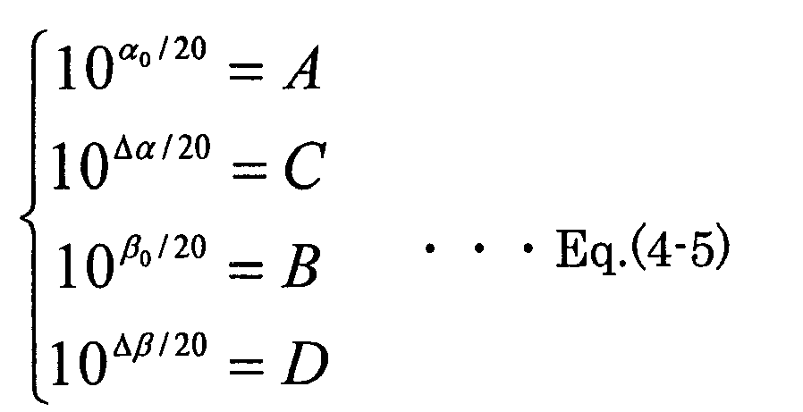

- If Eq.(4-2) is substituted for Eqs.(4-5) and (4-6), the following equations can be obtained:


- It has been indicated in the above that a change amount D of the gain_ β (n) is controlled so as to be equal to an inverse number of a change amount C of the gain_α (n). However, the change amount D of the gain_ β (n) may be controlled in inverse proportion as the following equation, instead of Eq.(4-7) or based on the inverse number.

where L and f( ) respectively indicate an arbitrary constant and an arbitrary function. - Also, while a method of controlling the recording volume adjustment amount based on the change amount of the reproduction volume adjustment amount has been indicated in the above-mentioned description, it may be controlled based on an absolute amount of the reproduction volume adjustment amount.
- Also, the control means 6 may determine the reproduction volume adjustment amount α (n) [dB] based on the reproduction volume set value X.
- Furthermore, by providing the transmission volume adjusting means (not shown) for adjusting the volume of the transmitting signal, the control means 6 may determine the transmission volume adjustment amount for the transmission volume adjusting means based on the above-mentioned reproduction volume adjustment amount α (n) [dB]. In this case, it is possible to control the transmission volume adjustment amount based on the inverse number of the recording volume adjustment amount or in inverse proportion to the recording volume adjustment amount, namely so as to be equal to the reproduction volume adjustment amount. Thus, the input signal in(n) [dB] reduced by the recording volume adjusting means 5 can be compensated.
- Furthermore, by using a transmission volume set value, the control means 6 may determine the above-mentioned transmission volume adjustment amount.
- Furthermore, each of the above-mentioned adjusting means may comprise either a digital amplifier or an analog amplifier.
-
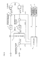
- Fig.1 is a block diagram showing a principle of a voice communication device according to the present invention;
- Fig.2 is a block diagram showing a system arrangement with a handsfree communication function where a voice communication device according to the present invention is incorporated;
- Fig.3 is a block diagram showing an embodiment (1) of a voice communication device according to the present invention shown in Fig.1;
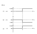
- Fig.4 is a time chart of volume adjustment amounts of a voice communication device according to the present invention shown in Fig.3;
- Fig.5 is a time chart showing a difference between voice adjustment amounts of a prior art example and the present invention;
- Fig.6 is a block diagram showing an embodiment (2) of a voice communication device according to the present invention shown in Fig. 1;
- Fig.7 is a block diagram showing a prior art voice communication device which has been generally known;
- Fig.8 is a block diagram showing a voice communication device that is an improved version of the voice communication device shown in the prior art example of Fig.7; and
- Fig.9 is a diagram for illustrating a problem of a prior art technology.
-
- 1 signal processing means
- 2 reproduction volume adjusting means (amplifier)
- 3 reproducing means (speaker)
- 4 recording means (microphone)
- 5 recording volume adjusting means (amplifier)
- 6 control means (controller)
- 7 transmission volume adjusting amplifier
- 8 reproduction volume setting portion
- 9 D/A converter
- 10 A/D converter
- 11 transmission volume setting portion
- Throughout the figures, like reference numerals indicate like or corresponding components.
- Fig.2 shows a system arrangement where a voice communication device according to the present invention is incorporated. A handsfree function of an IP telephone software in a personal computer is incorporated into the voice communication device according to the present invention in a
mobile telephone 100 connected to apublic network 200. Namely, themobile telephone 100 is provided with avoice communication device 103 receiving a received signal r(n) obtained through adecoder 102 which decodes a digital signal from areceiver 101 receiving an analog signal from thepublic network 200 to be converted into the digital signal, into the original code. Thisvoice communication device 103 is for transmitting a transmitting signal s(n) encoded by theencoder 104 to thepublic network 200 after the signal is converted from the digital signal into the analog signal by atransmitter 105. An output sound V1 of thevoice communication device 103 is provided to atalker 300 and a talker voice V2 from thetalker 300 is received by thevoice communication device 103. - Fig.3 shows an arrangement of the above-mentioned
voice communication device 103 in Fig.2 as well as an embodiment of the voice communication device shown in Fig.1. - Firstly, variables in the embodiment shown in Fig.3 are indicated in the following tables:
TABLE 1 EXPLANATION OF VARIABLE (1) (2) VARIABLE CONTENT VARIABLE CONTENT r(n) RECEIVED SIGNAL X REPRODUCTION VOLUME SET VALUE s(n) TRANSMITTING SIGNAL α (n) REPRODUCTION VOLUME ADJUSTMENT AMOUNT (dB) spe(n) SPEAKER SIGNAL β (n) RECORDING VOLUME ADJUSTMENT AMOUNT (dB) mic(n) MICROPHONE SIGNAL γ (n) TRANSMISSION VOLUME ADJUSTMENT AMOUNT (dB) in(n) INPUT SIGNAL OF EC ERL(n) ERL(dB) AT EC out(n) OUTPUT SIGNAL OF EC ERL0 ACOUSTIC COUPLING AMOUNT (dB) BETWEEN SPEAKER & MICROPHONE - Namely, in the voice communication device of this embodiment shown in Fig.1, an echo canceller (EC) is used as the signal processing means 1, and volume adjusting amplifiers are respectively used as the volume adjusting means 2 and 5. Also, a transmission volume adjusting amplifier (digital amplifier) 7 is used on the output side of the
echo canceller 1. Furthermore, a D/A converter 9 is provided between the reproduction volume adjusting amplifier (digital amplifier) 2 and the speaker (reproduction means) 3, and an A/D converter 10 is provided between the microphone (recording means) 4 and the recording volume adjusting amplifier (digital amplifier) 5. Furthermore, for providing the reproduction volume set value X shown in Fig.1, a reproductionvolume setting portion 8 is connected to thecontroller 6 as the control means. - In Fig.3, the
controller 6 provides the reproduction volume adjustment amount α (n) [dB] to the reproductionvolume adjusting amplifier 2 based on the reproduction volume set value X from the reproductionvolume setting portion 8, for example, the received signal r(n) is amplified by α [dB] to assume the speaker signal spe(n). The speaker signal spe(n) is converted from the digital signal into the analog signal at the D/A converter 9 to be transmitted to thespeaker 3. The speaker signal spe(n) at this time can be expressed by the following equation:
- On the other hand, the recording analog signal from the
microphone 4 is converted into the digital signal mic(n) at the A/D converter 10 to be provided to the recordingvolume adjusting amplifier 5. To the recordingvolume adjusting amplifier 5, the recording volume adjustment amount β (n) [dB] is provided from thecontroller 6, so that the input of the recordingvolume adjusting amplifier 5 is amplified by the recording volume adjustment amount β (n) [dB] to be provided to theecho canceller 1 as the input signal in(n). The input signal in(n) at this time can be expressed by the following equation:
- Furthermore, an output signal out(n) from the
echo canceller 1 is transmitted to the transmissionvolume adjusting amplifier 7, to which a transmission volume adjustment amount γ [dB] is provided from thecontroller 6. Therefore, the output signal out(n) is amplified by the transmission volume adjustment amount γ (n) [dB], so that the transmitting signal s(n) is outputted to the opponent. The transmitting signal s(n) at this time can be expressed by the following equation:
- At the reproduction
volume setting portion 8, thetalker 300 can select the reproduction volume set value during communication from among 5 stages (1-5). The initial value is set to "3". When the reproduction volume set value X is provided to thecontroller 6 from the reproductionvolume setting portion 8, thecontroller 6 transmits the reproduction volume adjustment amount α (n) [dB] corresponding to the reproduction volume set value X to the reproductionvolume adjusting amplifier 2. The relationship between the reproduction volume set value X and the reproduction volume adjustment amount α (n) [dB] is indicated in the following table:TABLE 2 RELATIONSHIP BETWEEN REPRODUCTION VOLUME SETTING AND REPRODUCTION VOLUME ADJUSTMENT AMOUNT REPRODUCTION VOLUME SET VALUE X REPRODUCTION VOLUME ADJUSTMENT AMOUNT α(n)[dB] 5 +12 4 +6 3 0 2 -6 1 -12 - The ERL(n) at the
echo canceller 1 at this time can be expressed by the following equation:
- Also, the recording volume adjustment amount β [dB] and the transmission volume adjustment amount γ (n) [dB] determined based on the reproduction volume set value X by the
controller 6 can be obtained by the following equations:

- Accordingly, if Eqs.(11) and (12) are substituted for the above-mentioned Eq.(10), the ERL(n) at the
echo canceller 1 can be expressed by the following equation:
- The meaning of this Eq.(13) will now be described. When the reproduction volume set value X is changed from "3" (0 dB) to "5" (12 dB) at the above-mentioned time "m", the reproduction volume adjustment amount α (n) [dB], the recording volume adjustment amount β (n) [dB], and the transmission volume adjustment amount γ (n) [dB] are respectively controlled as shown by Figs.4(1)-(3).
- When the volume adjustment shown by the above-mentioned Eqs.(11) and Eq.(12) is not performed (prior art example), the ERL(n) [dB] at the
echo canceller 1 is rapidly decreased from ERL0 by 12 dB at the time "m". - On the other hand, when the volume adjustment shown in Eqs.(11) and (12) is performed, it is found by Eq.(13) that the ERL(n) [dB] at the
echo canceller 1 becomes the fixed ERL0 at all of the time points as shown in Fig.4(2). - Thus, if the volume adjustment of the voice communication device according to the present invention is performed, the ERL(n) is stabilized, and the operation of the
echo canceller 1 is stably held, so that a good handsfree communication can be realized. - Fig.6 shows an embodiment (2) that is a modification of the embodiment shown in Fig.3. The embodiment (2) is provided with a transmission
volume setting portion 11 for setting a transmission volume set value Y in addition to the reproductionvolume setting portion 8 for setting the set value X. Also, in the embodiment (1) of Fig.3, the D/A converter 9 is provided between the reproduction volume adjusting amplifier (digital amplifier) 2 and thespeaker 3. However in this embodiment, different from the embodiment (1), the D/A converter 9 is moved to the preceding stage of the reproduction volume adjusting amplifier (analog amplifier) 2, and the A/D converter 10 is also moved to the interval between the recording volume adjusting amplifier (analog amplifier) 5 and theecho canceller 1 from the interval between themicrophone 4 and the recording volume amplifier (digital amplifier) 5. - It is to be noted that also in the embodiment (2), like the above-mentioned embodiment (1) of Fig.3, the speaker signal spe(n) is expressed by the reproduction
volume adjusting amplifier 2 according to Eq.(7), the input sound in(n) of theecho canceller 1 is expressed by the recordingvolume adjusting amplifier 5 according to Eq.(8), and the transmitting signal s(n) is expressed by the transmissionvolume adjusting amplifier 7 according to Eq.(9). - It is supposed in this embodiment (2) that the
talker 300 can select the volume set values X and Y during communication from among 256 stages (0-255), and also the initial values of the reproduction volume adjustment amount α (n) and the recording volume adjustment amount β (n) are respectively set to values α (0) and β (0) in the reproductionvolume setting portion 8 and the transmissionvolume setting portion 11. - Firstly, as for the reproduction volume set value X set by the reproduction
volume setting portion 8, thecontroller 6 provides the reproduction volume adjustment amount α (n) [dB] corresponding to the reproduction volume set value X to the reproductionvolume adjusting amplifier 2. The relationship between the reproduction volume set value X and the reproduction volume adjustment amount α (n) [dB] in this case is indicated in the following table:TABLE 3 RELATIONSHIP BETWEEN REPRODUCTION VOLUME SET VALUE AND REPRODUCTION VOLUME ADJUSTMENT AMOUNT REPRODUCTION VOLUME SET VALUE X REPRODUCTION VOLUME ADJUSTMENT AMOUNT α(n)[dB] 255 +20 254 +19.84 . . . . . . X 
. . . . . . 0 -20 - Also, the
controller 6 obtains the recording volume adjustment amount β (n) [dB] by the following equation to be transmitted to the recording volume adjusting amplifier 5:
- Furthermore, as for the transmission volume set value Y set by the transmission
volume setting portion 11, thecontroller 6 determines the transmission volume adjustment amount γ (n) by the following equation based on the transmission volume set value Y, the above-mentioned reproduction volume adjustment amount α and the initial values α (0) and β (0), so that the transmission volume adjustment amount γ (n) is transmitted to the transmission volume adjusting amplifier 7:
- The relationship between the transmission volume set value Y in this case and a volume 6 (n) [dB] in the above-mentioned Eq.(15) corresponding to the set value Y is indicated in following table:
TABLE 4 RELATIONSHIP BETWEEN TRANSMISSION VOLUME SET VALUE AND CORRESPONDING VOLUME TRANSMISSION VOLUME SET VALUE Y CORRESPONDING VOLUME δ (n) [dB] 255 +20 254 + 19.84 . . . . . . Y 
. . . . . . 0 -20 - The ERL(n) in the
echo canceller 1 in this case can be expressed by the following equation from the above-mentioned Eqs.(2) and (14):
- Since the ERL(n) of the
echo canceller 1 is expressed with ERL0, α (0), and β (0) by the above-mentioned Eq.(16), it is found that ERL(n) does not depend on the reproduction volume adjustment amount α (n). Namely, even if the set value X for the reproduction volume adjustment amount α (n) is changed, the ERL(n) is not changed. - A level difference SML between the transmission volume s(n) and a microphone signal mic(n) can be expressed by the following equation:

- If it is supposed that the
echo canceller 1 does not influence the volume of the inputted voice of thetalker 300, Eq.(17) can be expressed with the above-mentioned Eqs.(8) and (9) as follows:
- If the above-mentioned Eqs.(14) and (15) are substituted for Eq.(18), the following equation can be expressed:

- Accordingly, by the above-mentioned Eq.(19), the level difference SML can be expressed only by the volume 6 (n) corresponding to the set value Y. Therefore, it has been confirmed that the level difference SML does not depend on the change of the reproduction volume adjustment amount α (n) and the reproduction volume set value X.
- As mentioned above, according to the present invention, it becomes possible to realize an IP telephone software providing an optimum volume setting with respect to the following points:
- (1) It becomes possible for a user to set a listenable volume for the user by adjusting the reproduction volume:
- (2) Even if the reproduction volume is changed, the ERL(n) is fixed, so that the echo suppressing amount at the echo canceller can be kept from being reduced:
- (3) Even if the reproduction volume is changed, the volume of the talker's voice transmitted to the opponent is unchanged:
- (4) By adjusting the transmission volume, the volume of the talker's voice transmitted to the opponent can be set to a listenable volume for the opponent.
Claims (9)
- A voice communication device comprising:a first adjusting means adjusting a volume of a received signal;a second adjusting means adjusting a volume of a transmitting signal including the received signal having passed through an echo path; anda control means controlling an adjustment amount by the second adjusting means based on an adjustment amount by the first adjusting means.
- The voice communication device as claimed in claim 1, wherein the control means controls the adjustment amount by the second adjusting means based on an absolute value or a change amount of the adjustment amount by the first adjusting means.
- The voice communication device as claimed in claim 1 or 2, wherein the control means controls the adjustment amount by the second adjusting means based on an inverse number of the adjustment amount by the first adjusting means or in inverse proportion to the adjustment amount of the first adjusting means.
- The voice communication device as claimed in claim 1, further comprising a signal processing means removing or suppressing an echo signal that is the received signal inputted to a transmission side through the echo path.
- The voice communication device as claimed in claim 1, wherein the control means determines the adjustment amount by the first adjusting means based on a set volume of the received signal.
- The voice communication device as claimed in claim 1, further comprising a third adjusting means adjusting the volume of the transmitting signal on an output side of the second adjusting means, the control means also determining an adjustment amount of the transmitting signal for the third adjusting means based on the adjustment amount of the first adjusting means.
- The voice communication device as claimed in claim 6, wherein the control means controls the adjustment amount by the third adjusting means based on an inverse number of the adjustment amount by the second adjusting means or in inverse proportion to the adjustment amount by the second adjusting means.
- The voice communication device as claimed in claim 6, wherein the control means changes the adjustment amount by the third adjusting means based on a set adjustment amount of the transmitting signal.
- The voice communication device as claimed in claim 1, wherein each adjusting means comprises a digital amplifier or an analog amplifier.
Applications Claiming Priority (1)
| Application Number | Priority Date | Filing Date | Title |
|---|---|---|---|
| PCT/JP2004/003613 WO2005091519A1 (en) | 2004-03-18 | 2004-03-18 | Voice speaking device |
Publications (2)
| Publication Number | Publication Date |
|---|---|
| EP1727295A1 true EP1727295A1 (en) | 2006-11-29 |
| EP1727295A4 EP1727295A4 (en) | 2008-07-23 |
Family
ID=34994045
Family Applications (1)
| Application Number | Title | Priority Date | Filing Date |
|---|---|---|---|
| EP04721712A Withdrawn EP1727295A4 (en) | 2004-03-18 | 2004-03-18 | VOICE COMMUNICATION DEVICE |
Country Status (4)
| Country | Link |
|---|---|
| US (1) | US20060245584A1 (en) |
| EP (1) | EP1727295A4 (en) |
| JP (1) | JPWO2005091519A1 (en) |
| WO (1) | WO2005091519A1 (en) |
Cited By (1)
| Publication number | Priority date | Publication date | Assignee | Title |
|---|---|---|---|---|
| WO2017166747A1 (en) * | 2016-04-01 | 2017-10-05 | 乐视控股(北京)有限公司 | Method and apparatus for adjusting recording volume, and electronic device |
Families Citing this family (1)
| Publication number | Priority date | Publication date | Assignee | Title |
|---|---|---|---|---|
| CN108322859A (en) * | 2018-02-05 | 2018-07-24 | 北京百度网讯科技有限公司 | Apparatus, method and computer readable storage medium for echo cancellation |
Family Cites Families (7)
| Publication number | Priority date | Publication date | Assignee | Title |
|---|---|---|---|---|
| JPH0244408B2 (en) * | 1984-09-03 | 1990-10-03 | Nippon Denki Kk | EKOOKYANSERAGATASOHOKOZOFUKUKI |
| JPH043629A (en) | 1990-04-20 | 1992-01-08 | Fujitsu Ltd | Echo canceller device |
| JPH06104970A (en) * | 1992-09-18 | 1994-04-15 | Fujitsu Ltd | Loud phone |
| JPH08335976A (en) * | 1995-06-06 | 1996-12-17 | Kobe Steel Ltd | Loudspeaking device |
| JP2001044869A (en) * | 1999-07-26 | 2001-02-16 | Sony Corp | Receiving apparatus and receiving state detecting method |
| JP2001044896A (en) | 1999-08-03 | 2001-02-16 | Matsushita Electric Ind Co Ltd | Speech unit and speech method |
| JP3576430B2 (en) * | 1999-09-01 | 2004-10-13 | 沖電気工業株式会社 | Automatic gain controller |
-
2004
- 2004-03-18 WO PCT/JP2004/003613 patent/WO2005091519A1/en not_active Ceased
- 2004-03-18 JP JP2006511090A patent/JPWO2005091519A1/en active Pending
- 2004-03-18 EP EP04721712A patent/EP1727295A4/en not_active Withdrawn
-
2006
- 2006-06-27 US US11/475,628 patent/US20060245584A1/en not_active Abandoned
Non-Patent Citations (2)
| Title |
|---|
| No further relevant documents disclosed * |
| See also references of WO2005091519A1 * |
Cited By (1)
| Publication number | Priority date | Publication date | Assignee | Title |
|---|---|---|---|---|
| WO2017166747A1 (en) * | 2016-04-01 | 2017-10-05 | 乐视控股(北京)有限公司 | Method and apparatus for adjusting recording volume, and electronic device |
Also Published As
| Publication number | Publication date |
|---|---|
| JPWO2005091519A1 (en) | 2008-02-07 |
| WO2005091519A1 (en) | 2005-09-29 |
| EP1727295A4 (en) | 2008-07-23 |
| US20060245584A1 (en) | 2006-11-02 |
Similar Documents
| Publication | Publication Date | Title |
|---|---|---|
| US5640450A (en) | Speech circuit controlling sidetone signal by background noise level | |
| CN100514989C (en) | Microphone gains regulator of communication device | |
| JP5177820B2 (en) | System and method for enhanced subjective stereo audio | |
| KR20020071967A (en) | Improved system and method for implementation of an echo canceller | |
| KR20010032999A (en) | Audio codec with agc controlled by a vocoder | |
| JPH08223089A (en) | Method and equipment of echo cancellation for all dual connection | |
| JP2003249996A (en) | Sound signal input/output device | |
| US5790657A (en) | Echo suppressor capable of suppressing an echo resulting from acoustic coupling without spoiling a natural sound of conversation | |
| CN1106748C (en) | Apparatus and method for providing telephone user with control of threshold volume at which user's voice will take control of half-duplex speakerphone conversation | |
| EP1727295A1 (en) | Voice speaking device | |
| US20050063533A1 (en) | Microprocessor-controlled full-duplex speakerphone using automatic gain control | |
| US20060008091A1 (en) | Apparatus and method for cross-talk cancellation in a mobile device | |
| US7760869B2 (en) | Method and apparatus for controlling the transmit volume level of a speakerphone | |
| US6711259B1 (en) | Method and apparatus for noise suppression and side-tone generation | |
| WO2024076810A1 (en) | Methods, apparatus and systems for performing perceptually motivated gain control | |
| KR100325135B1 (en) | A Voice Signal Error Compensation Algorithm | |
| US20020164039A1 (en) | Method for controlling multi-mode audio gain balance | |
| JPH0530177A (en) | Side tone control circuit of handset | |
| JP3221937B2 (en) | Wireless telephone equipment | |
| KR100369647B1 (en) | Gain controlling methode for analyzing of hand-free function | |
| JP3019467B2 (en) | Audio mixer | |
| CA1110704A (en) | Level control circuitry for two way communication system | |
| JPH11284550A (en) | Voice input-output device | |
| JPS61260752A (en) | Acoustic detour signal suppressing circuit of conference talking device | |
| JP6775162B2 (en) | Calling device and calling system using it |
Legal Events
| Date | Code | Title | Description |
|---|---|---|---|
| PUAI | Public reference made under article 153(3) epc to a published international application that has entered the european phase |
Free format text: ORIGINAL CODE: 0009012 |
|
| 17P | Request for examination filed |
Effective date: 20060718 |
|
| AK | Designated contracting states |
Kind code of ref document: A1 Designated state(s): DE FR GB |
|
| DAX | Request for extension of the european patent (deleted) | ||
| RBV | Designated contracting states (corrected) |
Designated state(s): DE FR GB |
|
| A4 | Supplementary search report drawn up and despatched |
Effective date: 20080620 |
|
| RIC1 | Information provided on ipc code assigned before grant |
Ipc: H04M 9/08 20060101ALI20080616BHEP Ipc: H04B 3/20 20060101AFI20080616BHEP Ipc: H04M 1/60 20060101ALI20080616BHEP |
|
| 17Q | First examination report despatched |
Effective date: 20080910 |
|
| STAA | Information on the status of an ep patent application or granted ep patent |
Free format text: STATUS: THE APPLICATION IS DEEMED TO BE WITHDRAWN |
|
| 18D | Application deemed to be withdrawn |
Effective date: 20110224 |