EP1726879B1 - Reduced-weight fuel system for a gas turbine engine, gas turbine engine including such a system, and method of providing fuel to such a gas turbine engine - Google Patents
Reduced-weight fuel system for a gas turbine engine, gas turbine engine including such a system, and method of providing fuel to such a gas turbine engine Download PDFInfo
- Publication number
- EP1726879B1 EP1726879B1 EP06114572.8A EP06114572A EP1726879B1 EP 1726879 B1 EP1726879 B1 EP 1726879B1 EP 06114572 A EP06114572 A EP 06114572A EP 1726879 B1 EP1726879 B1 EP 1726879B1
- Authority
- EP
- European Patent Office
- Prior art keywords
- fuel
- gas turbine
- turbine engine
- fuel pump
- engine
- Prior art date
- Legal status (The legal status is an assumption and is not a legal conclusion. Google has not performed a legal analysis and makes no representation as to the accuracy of the status listed.)
- Ceased
Links
- 239000000446 fuel Substances 0.000 title claims description 151
- 238000000034 method Methods 0.000 title claims description 11
- 238000002485 combustion reaction Methods 0.000 claims description 11
- 238000011144 upstream manufacturing Methods 0.000 claims description 4
- 239000013589 supplement Substances 0.000 claims 1
- 239000007789 gas Substances 0.000 description 25
- 239000007858 starting material Substances 0.000 description 5
- 239000002828 fuel tank Substances 0.000 description 2
- 238000012986 modification Methods 0.000 description 2
- 230000004048 modification Effects 0.000 description 2
- 238000005086 pumping Methods 0.000 description 2
- 238000007792 addition Methods 0.000 description 1
- 238000001816 cooling Methods 0.000 description 1
- 238000006073 displacement reaction Methods 0.000 description 1
- 239000012530 fluid Substances 0.000 description 1
- 230000037361 pathway Effects 0.000 description 1
- 239000002918 waste heat Substances 0.000 description 1
Images

Classifications
-
- F—MECHANICAL ENGINEERING; LIGHTING; HEATING; WEAPONS; BLASTING
- F02—COMBUSTION ENGINES; HOT-GAS OR COMBUSTION-PRODUCT ENGINE PLANTS
- F02C—GAS-TURBINE PLANTS; AIR INTAKES FOR JET-PROPULSION PLANTS; CONTROLLING FUEL SUPPLY IN AIR-BREATHING JET-PROPULSION PLANTS
- F02C7/00—Features, components parts, details or accessories, not provided for in, or of interest apart form groups F02C1/00 - F02C6/00; Air intakes for jet-propulsion plants
- F02C7/22—Fuel supply systems
- F02C7/236—Fuel delivery systems comprising two or more pumps
-
- F—MECHANICAL ENGINEERING; LIGHTING; HEATING; WEAPONS; BLASTING
- F02—COMBUSTION ENGINES; HOT-GAS OR COMBUSTION-PRODUCT ENGINE PLANTS
- F02C—GAS-TURBINE PLANTS; AIR INTAKES FOR JET-PROPULSION PLANTS; CONTROLLING FUEL SUPPLY IN AIR-BREATHING JET-PROPULSION PLANTS
- F02C7/00—Features, components parts, details or accessories, not provided for in, or of interest apart form groups F02C1/00 - F02C6/00; Air intakes for jet-propulsion plants
- F02C7/26—Starting; Ignition
- F02C7/262—Restarting after flame-out
-
- F—MECHANICAL ENGINEERING; LIGHTING; HEATING; WEAPONS; BLASTING
- F23—COMBUSTION APPARATUS; COMBUSTION PROCESSES
- F23K—FEEDING FUEL TO COMBUSTION APPARATUS
- F23K5/00—Feeding or distributing other fuel to combustion apparatus
- F23K5/02—Liquid fuel
- F23K5/14—Details thereof
- F23K5/142—Fuel pumps
-
- F—MECHANICAL ENGINEERING; LIGHTING; HEATING; WEAPONS; BLASTING
- F23—COMBUSTION APPARATUS; COMBUSTION PROCESSES
- F23R—GENERATING COMBUSTION PRODUCTS OF HIGH PRESSURE OR HIGH VELOCITY, e.g. GAS-TURBINE COMBUSTION CHAMBERS
- F23R3/00—Continuous combustion chambers using liquid or gaseous fuel
- F23R3/28—Continuous combustion chambers using liquid or gaseous fuel characterised by the fuel supply
-
- F—MECHANICAL ENGINEERING; LIGHTING; HEATING; WEAPONS; BLASTING
- F05—INDEXING SCHEMES RELATING TO ENGINES OR PUMPS IN VARIOUS SUBCLASSES OF CLASSES F01-F04
- F05D—INDEXING SCHEME FOR ASPECTS RELATING TO NON-POSITIVE-DISPLACEMENT MACHINES OR ENGINES, GAS-TURBINES OR JET-PROPULSION PLANTS
- F05D2260/00—Function
- F05D2260/85—Starting
-
- F—MECHANICAL ENGINEERING; LIGHTING; HEATING; WEAPONS; BLASTING
- F05—INDEXING SCHEMES RELATING TO ENGINES OR PUMPS IN VARIOUS SUBCLASSES OF CLASSES F01-F04
- F05D—INDEXING SCHEME FOR ASPECTS RELATING TO NON-POSITIVE-DISPLACEMENT MACHINES OR ENGINES, GAS-TURBINES OR JET-PROPULSION PLANTS
- F05D2270/00—Control
- F05D2270/01—Purpose of the control system
- F05D2270/09—Purpose of the control system to cope with emergencies
- F05D2270/092—Purpose of the control system to cope with emergencies in particular blow-out and relight
-
- Y—GENERAL TAGGING OF NEW TECHNOLOGICAL DEVELOPMENTS; GENERAL TAGGING OF CROSS-SECTIONAL TECHNOLOGIES SPANNING OVER SEVERAL SECTIONS OF THE IPC; TECHNICAL SUBJECTS COVERED BY FORMER USPC CROSS-REFERENCE ART COLLECTIONS [XRACs] AND DIGESTS
- Y02—TECHNOLOGIES OR APPLICATIONS FOR MITIGATION OR ADAPTATION AGAINST CLIMATE CHANGE
- Y02T—CLIMATE CHANGE MITIGATION TECHNOLOGIES RELATED TO TRANSPORTATION
- Y02T50/00—Aeronautics or air transport
- Y02T50/60—Efficient propulsion technologies, e.g. for aircraft
Definitions
- the present invention is directed to an improved fuel system for a gas turbine engine, a gas turbine engine including such an improved fuel system and a method of providing fuel to a gas turbine engine using an improved fuel system, and, more specifically, toward a reduced-weight fuel system for a gas turbine engine including an auxiliary fuel pump, a gas turbine engine including a reduced-weight fuel system having an auxiliary fuel pump, and a method of supplying fuel to a gas turbine engine using a reduced-weight fuel system including an auxiliary fuel pump.
- Gas turbine engines such as those found on jet aircraft, comprise a housing within which fuel and air are combined and burned. Such engines generally include vanes for drawing air into the housing and a compressor that compresses the air and sends it to a gas generator. In the gas generator, a precisely metered supply of fuel is mixed with the compressed air and burned. Expanding exhaust gasses turn a turbine which turns a shaft that provides power to the compressor, a fuel pump, and other elements associated with the engine. The exhaust gasses then pass through the remainder of the housing and exit the housing to provide thrust.
- a starter which is not part of the gas turbine engine or aircraft, is generally used to start a gas turbine engine.
- the starter causes the engine shaft to rotate at about 10 to 25 percent of its rated speed. This causes the compressor to compress air and the fuel pump to pump fuel to the gas generator. Once the fuel in the gas generator is successfully ignited, expanding exhaust gasses turn the turbine and the shaft and provide power for the compressor and fuel pump so that the starter is no longer needed.
- Engines are generally designed to start reliably when their shaft is rotating at a certain percentage of rated speed. This does not mean that the engine will never start at a lower speed, but that starts at such lower speeds are not as likely to occur as when the engine is turning at an intended starting speed. It is generally desirable to turn an engine shaft at about 10 percent of its rated speed during engine start-up; at lower speeds starting may be difficult because, for example, the fuel pump may provide fuel at too low a rate for a reliable start.
- the fuel pump used on a gas turbine engine must be large enough to provide fuel over a wide range of engine operating speeds.
- a fuel pump capable of supplying an engine with fuel under normal operating conditions may not supply adequate fuel for a windmill start. Therefore, it is known to provide gas turbine engines with fuel pumps that are, for example, 50 to 100 percent larger than necessary for normal engine operation to ensure that the fuel pump can provide an adequate fuel supply at low windmilling shaft speeds.
- US3589836 discloses as fuel pumping system comprising a main and auxiliary fuel pump driven by the same drive shaft using a gearing arrangement.
- FR1541486 discloses a gas turbine engine with a main pump feeding the combustion chamber of the turbine and an auxiliary pump which feeds a pilot light.
- US2607297 discloses a fuel pumping system for a gas turbine engine with main and auxiliary fuel pumps that can be independently driven.
- FIG. 1 schematically illustrates an aircraft fuel system 10 comprising a fuel tank 12, a main fuel pump 14, and a fuel metering unit 16 providing fuel to an engine 18.
- a main fuel pump input fuel line 20 connects the fuel tank 12 to a first input 22 of the main fuel pump 14, and a main fuel pump output fuel tine 24 leads from main fuel pump output 26 to fluid metering unit 16.
- Main fuel pump 14 comprises a gear pump and includes gears 28 driven by a shaft 30 powered by the rotation of engine 18 in a well-known manner.
- fuel metering unit 16 includes a recirculation output 32 for returning unneeded fuel to a recirculation input 34 of main fuel pump 14.
- a recirculation pathway 36 in main fuel pump 14 returns fuel to a point upstream of gears 28 where it is again pumped toward fuel metering unit 16.
- a first check valve 38 is provided upstream of gears 28 to substantially prevent reverse flows of fuel through main fuel pump output fuel line 24.
- Fuel system 10 further includes an auxiliary pump 40 connected to main fuel pump input line 20 at a point upstream from main fuel pump 20 and having an output 42 that flows through a second check valve 44 and enters main fuel pump output fuel line 24 at a point downstream of the main fuel pump output 26.
- Auxiliary pump 40 pumps at a rate that is controllable independently of the rate of rotation of shaft 30.
- auxiliary pump 40 is an electric pump driven by the electrical system of an aircraft (not shown) in which fuel system 10 is located.
- Auxiliary pump 40 may be, for example, a fixed displacement pump.
- Engine 18 requires that fuel be provided at a first, or start-up, rate in order to achieve a reliable start. If fuel is provided at a lower rate than this startup rate, the engine may sometimes start, but not as reliably.
- a rate "required" for startup is a rate necessary for reliable startup; it is possible that an engine will occasionally restart when fuel is provided at less than the "required” rate.
- Main fuel pump 14 is sized so that it can provide a fuel at this start-up rate when a starter turns engine 18 at about 10 percent of its rated speed.
- Main fuel pump 14 is also sized so that it can provide a required supply of fuel to engine 18 under all normal operating conditions, and might be expected to produce an output of about, for example, 1 kg/s (8000 Ib/hour).
- Auxiliary pump 40 is relatively small, and in this embodiment has an output of less than about 0.025 kg/s (200 Ib/hour). Auxiliary pump 40 will, according to the invention, produce an output of less than about 2.5 percent of the rated output of main fuel pump 14 and may produce an output pressure less than about one fifth of the maximum output pressure of main fuel pump 14.
- auxiliary fuel pump 40 During normal engine operation, auxiliary fuel pump 40 is generally not used. Instead, main fuel pump 14 supplies engine 18 with all fuel necessary for normal operation. Second check valve 44 substantially prevents fuel from flowing from main fuel pump output fuel line 24 to auxiliary pump 40. However, if engine 18 experiences a blow-out during flight and combustion ceases, engine 18 must be restarted without the use of a separate starter. Under these conditions, air flowing through engine 18 will turn shaft 30 and the compressor blades (not shown) on engine 18 and thus operate main fuel pump 14. The windmilling shaft 30, however, will generally not turn shaft 30 at the 10 percent of rated speed required for a reliable restart.
- Shaft 30 may only turn at 5 percent rated speed, for example, under such conditions, and the windmilling output rate of main fuel pump 14 will therefore be inadequate to reliably restart engine 18.
- auxiliary pump 40 is actuated to operate in parallel with the windmilling output of main fuel pump 14.
- auxiliary pump 40 is sized to provide an output rate equal to at least the difference between the output rate of main fuel pump 14 required for normal start up and the output rate of main fuel pump 14 under windmilling conditions.
- the auxiliary pump 40 and main fuel pump 14 in parallel will provide adequate fuel for an engine restart.
- auxiliary pump 40 allows for a significant reduction in the size of main fuel pump 14 in that main fuel pump need only be large enough to supply fuel to engine 18 under normal operating conditions and does not have to supply fuel to engine 18 on its own during a windmill restart.
- the combined weight and heat output of such a smaller main fuel pump 14 and auxiliary pump 14 is less than the weight of a main fuel pump that heretofore would have been required.
- the smaller main fuel pump 14 also generates less waste heat than would have been produced by a larger main fuel pump and therefore leaves a greater portion of the heat-absorbing capacity of the fuel system available for other types of cooling.
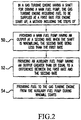
- Figure 2 illustrates a method of operating a gas turbine engine having a shaft for driving a main fuel pump which gas turbine engine requires fuel to be supplied at a first rate for engine start up.
- the method includes a step 50 of providing a main fuel pump having an output at a second rate less than the first rate when the shaft is windmilling, a step 52 of providing an auxiliary fuel pump having an output greater than or equal to a difference between the first rate and the second rate, and a step 54 of providing fuel to the gas turbine engine from the auxiliary fuel pump during windmill starts.
Landscapes
- Engineering & Computer Science (AREA)
- Chemical & Material Sciences (AREA)
- Combustion & Propulsion (AREA)
- Mechanical Engineering (AREA)
- General Engineering & Computer Science (AREA)
- Output Control And Ontrol Of Special Type Engine (AREA)
- Structures Of Non-Positive Displacement Pumps (AREA)
Description
- The present invention is directed to an improved fuel system for a gas turbine engine, a gas turbine engine including such an improved fuel system and a method of providing fuel to a gas turbine engine using an improved fuel system, and, more specifically, toward a reduced-weight fuel system for a gas turbine engine including an auxiliary fuel pump, a gas turbine engine including a reduced-weight fuel system having an auxiliary fuel pump, and a method of supplying fuel to a gas turbine engine using a reduced-weight fuel system including an auxiliary fuel pump.
- Gas turbine engines, such as those found on jet aircraft, comprise a housing within which fuel and air are combined and burned. Such engines generally include vanes for drawing air into the housing and a compressor that compresses the air and sends it to a gas generator. In the gas generator, a precisely metered supply of fuel is mixed with the compressed air and burned. Expanding exhaust gasses turn a turbine which turns a shaft that provides power to the compressor, a fuel pump, and other elements associated with the engine. The exhaust gasses then pass through the remainder of the housing and exit the housing to provide thrust.
- A starter, which is not part of the gas turbine engine or aircraft, is generally used to start a gas turbine engine. The starter causes the engine shaft to rotate at about 10 to 25 percent of its rated speed. This causes the compressor to compress air and the fuel pump to pump fuel to the gas generator. Once the fuel in the gas generator is successfully ignited, expanding exhaust gasses turn the turbine and the shaft and provide power for the compressor and fuel pump so that the starter is no longer needed.
- Engines are generally designed to start reliably when their shaft is rotating at a certain percentage of rated speed. This does not mean that the engine will never start at a lower speed, but that starts at such lower speeds are not as likely to occur as when the engine is turning at an intended starting speed. It is generally desirable to turn an engine shaft at about 10 percent of its rated speed during engine start-up; at lower speeds starting may be difficult because, for example, the fuel pump may provide fuel at too low a rate for a reliable start.
- Sometimes it becomes necessary to restart an engine while an aircraft is in flight. Air rushing through the engine housing of a non-functioning engine causes the blades on the compressor shaft to rotate and run the fuel pump. This rotation is sometimes referred to as "windmilling." An engine restart while its compressor is windmilling may be referred to as a "windmill start." The windmilling blades turn the engine shaft, but generally not at the 10 percent of rated engine speed considered desirable for a reliable engine start. In modem turbofan engines, for example, the windmilling blades may only turn the engine shaft at 5 percent of the rated engine speed. Other variables, such as airspeed when the restart becomes necessary, may further reduce the ability of the engine to be reliably windmill restarted.
- The fuel pump used on a gas turbine engine must be large enough to provide fuel over a wide range of engine operating speeds. However, a fuel pump capable of supplying an engine with fuel under normal operating conditions may not supply adequate fuel for a windmill start. Therefore, it is known to provide gas turbine engines with fuel pumps that are, for example, 50 to 100 percent larger than necessary for normal engine operation to ensure that the fuel pump can provide an adequate fuel supply at low windmilling shaft speeds.
- Using a fuel pump larger than is required for normal engine operation increases the weight and cost of a gas turbine engine. Furthermore, such a large fuel pump generates more heat than would be produced by a smaller fuel pump. This heat must be absorbed or dissipated by various heat sinks, such as the fuel supply, in the gas turbine engine, and this limits the amount of heat that these sinks can absorb from other sources. It would therefore be desirable to provide a gas turbine engine fuel system that would allow for reliable windmill engine restarts using a smaller fuel pump than has heretofore been possible.
-
US3589836 discloses as fuel pumping system comprising a main and auxiliary fuel pump driven by the same drive shaft using a gearing arrangement. -
FR1541486 -
US2607297 discloses a fuel pumping system for a gas turbine engine with main and auxiliary fuel pumps that can be independently driven. - In accordance with the present invention, there is provided a fuel system and a corresponding gas turbine and method as claimed in the accompanying claims.
- These aspects of the invention and others will be better understood after a reading of the following detailed description together with the following drawings wherein:
-
Figure 1 schematically illustrates a gas turbine engine and a fuel system according to an embodiment of the present invention; and -
Figure 2 is a flow chart outlining a method of operating the fuel system of claim 1. - Referring now to the drawings, wherein the showings are for purposes of illustrating preferred embodiments of the invention only and not for the purpose of limiting same,
Figure 1 schematically illustrates an aircraft fuel system 10 comprising afuel tank 12, amain fuel pump 14, and afuel metering unit 16 providing fuel to anengine 18. A main fuel pumpinput fuel line 20 connects thefuel tank 12 to afirst input 22 of themain fuel pump 14, and a main fuel pumpoutput fuel tine 24 leads from mainfuel pump output 26 tofluid metering unit 16.Main fuel pump 14 comprises a gear pump and includesgears 28 driven by ashaft 30 powered by the rotation ofengine 18 in a well-known manner. - Because
gears 28 pump fuel at a rate based on engine speed,main fuel pump 14 often provides fuel at a rate greater than the rate required byfuel metering unit 16 orengine 18. Therefore,fuel metering unit 16 includes arecirculation output 32 for returning unneeded fuel to arecirculation input 34 ofmain fuel pump 14. Arecirculation pathway 36 inmain fuel pump 14 returns fuel to a point upstream ofgears 28 where it is again pumped towardfuel metering unit 16. Afirst check valve 38 is provided upstream ofgears 28 to substantially prevent reverse flows of fuel through main fuel pumpoutput fuel line 24. - Fuel system 10 further includes an
auxiliary pump 40 connected to main fuelpump input line 20 at a point upstream frommain fuel pump 20 and having anoutput 42 that flows through a second check valve 44 and enters main fuel pumpoutput fuel line 24 at a point downstream of the mainfuel pump output 26.Auxiliary pump 40 pumps at a rate that is controllable independently of the rate of rotation ofshaft 30. According to the invention,auxiliary pump 40 is an electric pump driven by the electrical system of an aircraft (not shown) in which fuel system 10 is located.Auxiliary pump 40 may be, for example, a fixed displacement pump. -
Engine 18 requires that fuel be provided at a first, or start-up, rate in order to achieve a reliable start. If fuel is provided at a lower rate than this startup rate, the engine may sometimes start, but not as reliably. As used herein, a rate "required" for startup is a rate necessary for reliable startup; it is possible that an engine will occasionally restart when fuel is provided at less than the "required" rate.Main fuel pump 14 is sized so that it can provide a fuel at this start-up rate when a starter turnsengine 18 at about 10 percent of its rated speed.Main fuel pump 14 is also sized so that it can provide a required supply of fuel toengine 18 under all normal operating conditions, and might be expected to produce an output of about, for example, 1 kg/s (8000 Ib/hour). -
Auxiliary pump 40 is relatively small, and in this embodiment has an output of less than about 0.025 kg/s (200 Ib/hour).Auxiliary pump 40 will, according to the invention, produce an output of less than about 2.5 percent of the rated output ofmain fuel pump 14 and may produce an output pressure less than about one fifth of the maximum output pressure ofmain fuel pump 14. - During normal engine operation,
auxiliary fuel pump 40 is generally not used. Instead,main fuel pump 14supplies engine 18 with all fuel necessary for normal operation. Second check valve 44 substantially prevents fuel from flowing from main fuel pumpoutput fuel line 24 toauxiliary pump 40. However, ifengine 18 experiences a blow-out during flight and combustion ceases,engine 18 must be restarted without the use of a separate starter. Under these conditions, air flowing throughengine 18 will turnshaft 30 and the compressor blades (not shown) onengine 18 and thus operatemain fuel pump 14. Thewindmilling shaft 30, however, will generally not turnshaft 30 at the 10 percent of rated speed required for a reliable restart. Shaft 30 may only turn at 5 percent rated speed, for example, under such conditions, and the windmilling output rate ofmain fuel pump 14 will therefore be inadequate to reliably restartengine 18. Thus, when a windmill restart is necessary,auxiliary pump 40 is actuated to operate in parallel with the windmilling output ofmain fuel pump 14. - Thus,
auxiliary pump 40 is sized to provide an output rate equal to at least the difference between the output rate ofmain fuel pump 14 required for normal start up and the output rate ofmain fuel pump 14 under windmilling conditions. Thus, theauxiliary pump 40 andmain fuel pump 14 in parallel will provide adequate fuel for an engine restart. - The use of
auxiliary pump 40 allows for a significant reduction in the size ofmain fuel pump 14 in that main fuel pump need only be large enough to supply fuel toengine 18 under normal operating conditions and does not have to supply fuel toengine 18 on its own during a windmill restart. The combined weight and heat output of such a smallermain fuel pump 14 andauxiliary pump 14 is less than the weight of a main fuel pump that heretofore would have been required. The smallermain fuel pump 14 also generates less waste heat than would have been produced by a larger main fuel pump and therefore leaves a greater portion of the heat-absorbing capacity of the fuel system available for other types of cooling. -
Figure 2 illustrates a method of operating a gas turbine engine having a shaft for driving a main fuel pump which gas turbine engine requires fuel to be supplied at a first rate for engine start up. The method includes astep 50 of providing a main fuel pump having an output at a second rate less than the first rate when the shaft is windmilling, astep 52 of providing an auxiliary fuel pump having an output greater than or equal to a difference between the first rate and the second rate, and astep 54 of providing fuel to the gas turbine engine from the auxiliary fuel pump during windmill starts. - The present invention has been described herein in terms of a particular embodiment. However, obvious modifications and additions to this embodiment will become apparent to those skilled in the relevant arts upon a reading of the foregoing disclosure. It is intended that all such obvious modifications comprise a part of this invention to the extent they fall within the scope of the several claims appended hereto.
Claims (8)
- A fuel system (10) for a gas turbine engine (18) having a shaft (30), said fuel system (10) comprising:a main fuel pump (14), having an input fuel line (20), and an output fuel line (24)_for providing fuel to a combustion chamber of the gas turbine engine (18), said main fuel pump (14) driven by the shaft and having an output rate which varies with the rate of rotation of the shaft, an auxiliary fuel pump (40), connected to input fuel line (20) at a point upstream from main fuel pump (14), and having an output (42) that enters output fuel line (24) at a point downstream of the main fuel pump (14),_for providing fuel to the combustion chamber of the gas turbine engine (18), said auxiliary fuel pump (40) having an auxiliary output rate that is independent of the rate of rotation of the shaft and the output rate of the main fuel pump (14), characterized in that said auxiliary fuel pump (40) comprises an electric pump, and in that the maximum output rate of said auxiliary fuel pump (40) is less than 2.5 percent of said maximum output rate of the main fuel pump (14).
- The fuel system (10) of claim 1 wherein the maximum output pressure of said auxiliary fuel pump (40) is less than one fifth of the maximum output pressure of the main fuel pump.
- A gas turbine engine comprising:a rotatable shaft (30);a plurality of vanes connected to the rotatable shaft (30);a combustion chamber; anda fuel system according to any preceding claim.
- The gas turbine engine of claim 3 configured wherein, in use with an aircraft in flight and during normal engine operation, the main fuel pump (14) provides fuel to the combustion chamber of the gas turbine engine (18); and wherein, in use with an aircraft in flight when an engine restart is required, the auxiliary fuel pump (40) is actuated to ensure sufficient fuel is provided to the combustion chamber of the gas turbine engine (18) to restart the engine.
- The gas turbine engine of claim 3 configured wherein, in use with an aircraft in flight when an engine restart is required and the windmilling rate of the engine is insufficient to enable the main fuel pump (14) to provide fuel to the combustion chamber of the gas turbine engine (18) at a rate sufficient for restart, the auxiliary fuel pump (40) is actuated to supplement the fuel provided by the main fuel pump (14) to the combustion chamber of the gas turbine engine (18).
- A method of providing fuel to a gas turbine engine (10) using a fuel system as claimed in claim 1, said method comprising the step of:in use with an aircraft in flight when an engine restart is required, actuating the auxiliary fuel pump (40) to provide fuel to the combustion chamber of the gas turbine engine (18).
- The method of claim 6 wherein the auxiliary fuel pump (40) is used to provide fuel to the gas turbine engine (18) only during windmill starts.
- The method of claim 6 including the additional step of ceasing providing fuel to the gas turbine engine (18) using the auxiliary fuel pump (40) after combustion has started.
Applications Claiming Priority (1)
| Application Number | Priority Date | Filing Date | Title |
|---|---|---|---|
| US11/139,953 US7401461B2 (en) | 2005-05-27 | 2005-05-27 | Reduced-weight fuel system for gas turbine engine, gas turbine engine having a reduced-weight fuel system, and method of providing fuel to a gas turbine engine using a reduced-weight fuel system |
Publications (3)
| Publication Number | Publication Date |
|---|---|
| EP1726879A2 EP1726879A2 (en) | 2006-11-29 |
| EP1726879A3 EP1726879A3 (en) | 2007-07-18 |
| EP1726879B1 true EP1726879B1 (en) | 2017-10-25 |
Family
ID=36928241
Family Applications (1)
| Application Number | Title | Priority Date | Filing Date |
|---|---|---|---|
| EP06114572.8A Ceased EP1726879B1 (en) | 2005-05-27 | 2006-05-26 | Reduced-weight fuel system for a gas turbine engine, gas turbine engine including such a system, and method of providing fuel to such a gas turbine engine |
Country Status (2)
| Country | Link |
|---|---|
| US (1) | US7401461B2 (en) |
| EP (1) | EP1726879B1 (en) |
Families Citing this family (38)
| Publication number | Priority date | Publication date | Assignee | Title |
|---|---|---|---|---|
| FR2882095B1 (en) * | 2005-02-17 | 2011-05-06 | Hispano Suiza Sa | FUEL SUPPLY OF AN AIRCRAFT ENGINE |
| WO2007092456A2 (en) * | 2006-02-03 | 2007-08-16 | Rolls-Royce Corporation | Gas turbine engine fuel system with fuel metering valve |
| US7565793B2 (en) * | 2006-02-27 | 2009-07-28 | Honeywell International Inc. | Gas turbine engine fuel control system having start / back up check valve (SBUC) providing a main fuel check valve function |
| US7966994B2 (en) * | 2008-08-12 | 2011-06-28 | Woodcard, Inc. | System for metering a fuel supply |
| US8166765B2 (en) * | 2008-10-15 | 2012-05-01 | Woodward, Inc. | Fuel delivery and control system including a variable displacement actuation pump supplementing a fixed displacement main pump |
| US8302406B2 (en) * | 2008-10-15 | 2012-11-06 | Woodward, Inc. | Fuel delivery and control system including a positive displacement actuation pump with a variable pressure regulator supplementing a fixed displacement main fuel pump |
| FR2942271B1 (en) * | 2009-02-16 | 2011-05-13 | Hispano Suiza Sa | AERONAUTICAL MOTOR WITH COOLING OF AN ELECTRIC START-UP DEVICE |
| US8276360B2 (en) * | 2009-05-22 | 2012-10-02 | Hamilton Sundstrand Corporation | Dual-pump fuel system and method for starting a gas turbine engine |
| FR2950863B1 (en) * | 2009-10-06 | 2012-03-02 | Snecma | FUEL SUPPLY CIRCUIT FOR AN AIRCRAFT ENGINE |
| FR2953563B1 (en) * | 2009-12-07 | 2012-02-03 | Snecma | FUEL SUPPLY INSTALLATION OF AN AIRCRAFT TURBOJET ENGINE |
| US8584441B2 (en) * | 2010-01-05 | 2013-11-19 | Honeywell International Inc. | Fuel metering system electrically servoed metering pump |
| FR2960910A1 (en) * | 2010-06-08 | 2011-12-09 | Snecma | GAS TURBINE AIRCRAFT ENGINE FUEL SUPPLY DEVICE |
| US9151180B2 (en) | 2010-06-15 | 2015-10-06 | Hamilton Sundstrand Corporation | Lubrication driven gas turbine engine actuation system |
| FR2970053B1 (en) * | 2011-01-05 | 2013-01-25 | Turbomeca | DEVICE AND METHOD FOR MECHANICAL PROTECTION |
| US8893466B2 (en) | 2011-03-18 | 2014-11-25 | Hamilton Sundstrand Corporation | Dual pump fuel flow system for a gas turbine engine and method of controlling |
| US8408233B2 (en) | 2011-03-18 | 2013-04-02 | Hamilton Sundstrand Corporation | Flow control system and method for controlling two positive displacement pumps |
| US9206775B2 (en) | 2012-02-01 | 2015-12-08 | United Technologies Corporation | Fuel preheating using electric pump |
| US9316157B2 (en) * | 2012-02-01 | 2016-04-19 | Hamilton Sundstrand Corporation | Fuel system for starting an APU using a hybrid pump arrangement |
| US20140174409A1 (en) * | 2012-12-21 | 2014-06-26 | United Techologies Corporation | Gear Pump Protection Valve |
| US9885287B2 (en) | 2014-09-11 | 2018-02-06 | Honeywell International Inc. | Gas turbine engine mechanical-electrical hybrid fuel delivery system |
| US10208672B2 (en) * | 2015-02-09 | 2019-02-19 | United Technologies Corporation | Accumulator assisted gas turbine engine start system and methods therefor |
| US11236682B2 (en) * | 2018-02-22 | 2022-02-01 | Hamilton Sundstrand Corporation | Fuel pump systems for turbomachines |
| US11060461B2 (en) * | 2018-12-13 | 2021-07-13 | Hamilton Sundstrand Corporation | Fuel systems having reduced bypass flow |
| US11603802B2 (en) * | 2019-08-27 | 2023-03-14 | Pratt & Whitney Canada Corp. | Methods and systems for starting a gas turbine engine |
| US20210102517A1 (en) * | 2019-10-04 | 2021-04-08 | Hamilton Sundstrand Corporation | Electric pump assisted fuel system |
| CN111536548B (en) * | 2020-05-08 | 2021-07-02 | 山西大学 | A gravity self-stabilizing device for fuel system |
| FR3115075B1 (en) * | 2020-10-14 | 2022-10-21 | Safran Aircraft Engines | FUEL SUPPLY CIRCUIT FOR A TURBOMACHINE COMBUSTION CHAMBER |
| US11629640B2 (en) | 2021-09-08 | 2023-04-18 | Rolls-Royce North American Technologies Inc. | Oil pumping control for electrical oil pumping system |
| US11702990B2 (en) | 2021-09-08 | 2023-07-18 | Rolls-Royce North American Technologies Inc. | Redundant electrically driven fuel and oil pumping system for gas turbine with bidirectional pump motor |
| US11629643B1 (en) * | 2022-01-07 | 2023-04-18 | Hamilton Sundstrand Corporation | Fuel pump systems |
| US12366240B2 (en) | 2023-05-26 | 2025-07-22 | Hamilton Sundstrand Corporation | Pressure controlled pump systems |
| US11946420B1 (en) * | 2023-06-22 | 2024-04-02 | Hamilton Sundstrand Corporation | Fuel systems having thermal recirculation |
| US12571350B2 (en) | 2023-07-28 | 2026-03-10 | Rolls-Royce Corporation | Multi-modal gas-turbine engine starting |
| US20250035043A1 (en) * | 2023-07-28 | 2025-01-30 | Rolls-Royce North American Technologies, Inc. | Emergency start of a gas turbine engine |
| US12529340B2 (en) * | 2023-07-28 | 2026-01-20 | Rolls-Royce Corporation | Emergency start of a gas turbine engine |
| US12398678B2 (en) | 2023-07-28 | 2025-08-26 | Rolls-Royce Corporation | Motor and motor controller thermal management features |
| US12352211B1 (en) * | 2024-02-28 | 2025-07-08 | Hamilton Sundstrand Corporation | Dual pump electrified fuel system with parallelism |
| US12524027B2 (en) | 2024-04-22 | 2026-01-13 | Hamilton Sundstrand Corporation | Fuel system with boosted and cooled variable displacement main fuel pump and electromechanical actuators |
Citations (2)
| Publication number | Priority date | Publication date | Assignee | Title |
|---|---|---|---|---|
| US3259066A (en) * | 1964-01-02 | 1966-07-05 | Robert L Williams | Fuel feeding systems |
| US3275061A (en) * | 1964-01-02 | 1966-09-27 | Boeing Co | Fuel feeding systems |
Family Cites Families (16)
| Publication number | Priority date | Publication date | Assignee | Title |
|---|---|---|---|---|
| US2607297A (en) | 1945-05-03 | 1952-08-19 | Power Jets Res & Dev Ltd | Pressure fluid supply system |
| US2667742A (en) * | 1947-02-24 | 1954-02-02 | Bendix Aviat Corp | Starting system for gas turbine engines |
| US2916875A (en) | 1953-09-09 | 1959-12-15 | Rolls Royce | Gas turbine engine fuel systems |
| US3147712A (en) | 1960-09-02 | 1964-09-08 | Gen Motors Corp | Fuel pumping system for gas turbines |
| FR1541486A (en) | 1967-10-20 | 1968-10-04 | Lucas Industries Ltd | Fuel supply device for gas turbine engine |
| US3589836A (en) | 1968-11-04 | 1971-06-29 | Trw Inc | Unitized pump system |
| US3696612A (en) | 1970-12-30 | 1972-10-10 | Westinghouse Electric Corp | Fuel pump system for gas turbines |
| US4245964A (en) | 1978-11-08 | 1981-01-20 | United Technologies Corporation | Efficiency fluid pumping system including sequential unloading of a plurality of pumps by a single pressure responsive control valve |
| US4607486A (en) | 1983-12-02 | 1986-08-26 | United Technologies Corporation | Centrifugal main fuel pump |
| US4864815A (en) | 1987-12-24 | 1989-09-12 | Sundstrand Corporation | Fuel supply system with turbine driven start pump |
| US4915593A (en) | 1987-12-24 | 1990-04-10 | Sundstrand Corporation | Fluid supply system with turbine driven start pump |
| US5118258A (en) | 1990-09-04 | 1992-06-02 | United Technologies Corporation | Dual pump fuel delivery system |
| US5116362A (en) | 1990-12-03 | 1992-05-26 | United Technologies Corporation | Fuel metering and actuation system |
| GB9325029D0 (en) | 1993-12-07 | 1994-02-02 | Lucas Ind Plc | Pump |
| FR2816005B1 (en) | 2000-10-26 | 2003-01-17 | Snecma Moteurs | FUEL FLOW-SAVING CIRCUIT |
| EP1427928A1 (en) | 2001-08-27 | 2004-06-16 | Elliott Energy Systems, Inc. | Method for gas turbine light-off |
-
2005
- 2005-05-27 US US11/139,953 patent/US7401461B2/en active Active
-
2006
- 2006-05-26 EP EP06114572.8A patent/EP1726879B1/en not_active Ceased
Patent Citations (2)
| Publication number | Priority date | Publication date | Assignee | Title |
|---|---|---|---|---|
| US3259066A (en) * | 1964-01-02 | 1966-07-05 | Robert L Williams | Fuel feeding systems |
| US3275061A (en) * | 1964-01-02 | 1966-09-27 | Boeing Co | Fuel feeding systems |
Also Published As
| Publication number | Publication date |
|---|---|
| US20060266047A1 (en) | 2006-11-30 |
| US7401461B2 (en) | 2008-07-22 |
| EP1726879A2 (en) | 2006-11-29 |
| EP1726879A3 (en) | 2007-07-18 |
Similar Documents
| Publication | Publication Date | Title |
|---|---|---|
| US7401461B2 (en) | Reduced-weight fuel system for gas turbine engine, gas turbine engine having a reduced-weight fuel system, and method of providing fuel to a gas turbine engine using a reduced-weight fuel system | |
| EP3693578B1 (en) | Hybrid electric dual spool power extraction gearbox | |
| EP3708793B1 (en) | Lubrication systems and methods with superposition gearbox | |
| US5845483A (en) | Windmill engine starting system with fluid driven motor and pump | |
| US8276360B2 (en) | Dual-pump fuel system and method for starting a gas turbine engine | |
| EP3282093B1 (en) | Geared turbofan with low spool power extraction | |
| US7861533B2 (en) | Relighting a turbofan engine | |
| EP2133537B1 (en) | Bi-modal air turbine starter assembly | |
| US7040082B2 (en) | Assistance and emergency drive for electrically-driven accessories | |
| EP2609311B1 (en) | Method of optimising the operability of an aircraft motor drive and related autonomous powering group | |
| US20160237917A1 (en) | Method for optimising the specific consumption of a twin helicopter | |
| US20200158213A1 (en) | Hybrid electric propulsion with superposition gearbox | |
| US20180003072A1 (en) | Descent operation for an aircraft parallel hybrid gas turbine electric propulsion system | |
| EP1647675B1 (en) | Adequate oil supply for an aeroengine oil tank system | |
| US9951694B2 (en) | System and method for emergency starting of an aircraft turbomachine | |
| JP2017521585A (en) | Method for supporting a turboshaft engine in a stand-by state of a multi-engine helicopter and architecture of a propulsion system for a helicopter comprising at least one turboshaft engine capable of being put into a stand-by state | |
| CA2584371A1 (en) | Electric power generation system and method | |
| CA2602325A1 (en) | Gas turbine engine assembly and method of assembling same | |
| CN102383943B (en) | Auxiliary hydraulic power generation system | |
| EP3712406B1 (en) | Backup system for demand fuel pumping system | |
| CA3078274C (en) | Method for creating a required pressure and fuel flow rate in a fuel system of a gas turbine engine |
Legal Events
| Date | Code | Title | Description |
|---|---|---|---|
| PUAI | Public reference made under article 153(3) epc to a published international application that has entered the european phase |
Free format text: ORIGINAL CODE: 0009012 |
|
| AK | Designated contracting states |
Kind code of ref document: A2 Designated state(s): AT BE BG CH CY CZ DE DK EE ES FI FR GB GR HU IE IS IT LI LT LU LV MC NL PL PT RO SE SI SK TR |
|
| AX | Request for extension of the european patent |
Extension state: AL BA HR MK YU |
|
| PUAL | Search report despatched |
Free format text: ORIGINAL CODE: 0009013 |
|
| AK | Designated contracting states |
Kind code of ref document: A3 Designated state(s): AT BE BG CH CY CZ DE DK EE ES FI FR GB GR HU IE IS IT LI LT LU LV MC NL PL PT RO SE SI SK TR |
|
| AX | Request for extension of the european patent |
Extension state: AL BA HR MK YU |
|
| 17P | Request for examination filed |
Effective date: 20080107 |
|
| AKX | Designation fees paid |
Designated state(s): DE FR GB |
|
| 17Q | First examination report despatched |
Effective date: 20080229 |
|
| GRAP | Despatch of communication of intention to grant a patent |
Free format text: ORIGINAL CODE: EPIDOSNIGR1 |
|
| INTG | Intention to grant announced |
Effective date: 20170608 |
|
| GRAS | Grant fee paid |
Free format text: ORIGINAL CODE: EPIDOSNIGR3 |
|
| GRAA | (expected) grant |
Free format text: ORIGINAL CODE: 0009210 |
|
| AK | Designated contracting states |
Kind code of ref document: B1 Designated state(s): DE FR GB |
|
| REG | Reference to a national code |
Ref country code: GB Ref legal event code: FG4D |
|
| REG | Reference to a national code |
Ref country code: DE Ref legal event code: R096 Ref document number: 602006053919 Country of ref document: DE |
|
| REG | Reference to a national code |
Ref country code: FR Ref legal event code: PLFP Year of fee payment: 13 |
|
| REG | Reference to a national code |
Ref country code: DE Ref legal event code: R097 Ref document number: 602006053919 Country of ref document: DE |
|
| PLBE | No opposition filed within time limit |
Free format text: ORIGINAL CODE: 0009261 |
|
| STAA | Information on the status of an ep patent application or granted ep patent |
Free format text: STATUS: NO OPPOSITION FILED WITHIN TIME LIMIT |
|
| 26N | No opposition filed |
Effective date: 20180726 |
|
| PGFP | Annual fee paid to national office [announced via postgrant information from national office to epo] |
Ref country code: DE Payment date: 20190531 Year of fee payment: 14 |
|
| PGFP | Annual fee paid to national office [announced via postgrant information from national office to epo] |
Ref country code: FR Payment date: 20190528 Year of fee payment: 14 |
|
| PGFP | Annual fee paid to national office [announced via postgrant information from national office to epo] |
Ref country code: GB Payment date: 20190529 Year of fee payment: 14 |
|
| REG | Reference to a national code |
Ref country code: DE Ref legal event code: R119 Ref document number: 602006053919 Country of ref document: DE |
|
| GBPC | Gb: european patent ceased through non-payment of renewal fee |
Effective date: 20200526 |
|
| PG25 | Lapsed in a contracting state [announced via postgrant information from national office to epo] |
Ref country code: GB Free format text: LAPSE BECAUSE OF NON-PAYMENT OF DUE FEES Effective date: 20200526 Ref country code: FR Free format text: LAPSE BECAUSE OF NON-PAYMENT OF DUE FEES Effective date: 20200531 |
|
| PG25 | Lapsed in a contracting state [announced via postgrant information from national office to epo] |
Ref country code: DE Free format text: LAPSE BECAUSE OF NON-PAYMENT OF DUE FEES Effective date: 20201201 |
|
| P01 | Opt-out of the competence of the unified patent court (upc) registered |
Effective date: 20230830 |