EP1726785A2 - Turbine airfoil platform cooling circuit - Google Patents
Turbine airfoil platform cooling circuit Download PDFInfo
- Publication number
- EP1726785A2 EP1726785A2 EP06251550A EP06251550A EP1726785A2 EP 1726785 A2 EP1726785 A2 EP 1726785A2 EP 06251550 A EP06251550 A EP 06251550A EP 06251550 A EP06251550 A EP 06251550A EP 1726785 A2 EP1726785 A2 EP 1726785A2
- Authority
- EP
- European Patent Office
- Prior art keywords
- platform
- cooling circuit
- assembly
- cooling
- airfoil
- Prior art date
- Legal status (The legal status is an assumption and is not a legal conclusion. Google has not performed a legal analysis and makes no representation as to the accuracy of the status listed.)
- Granted
Links
Images

Classifications
-
- F—MECHANICAL ENGINEERING; LIGHTING; HEATING; WEAPONS; BLASTING
- F01—MACHINES OR ENGINES IN GENERAL; ENGINE PLANTS IN GENERAL; STEAM ENGINES
- F01D—NON-POSITIVE DISPLACEMENT MACHINES OR ENGINES, e.g. STEAM TURBINES
- F01D9/00—Stators
- F01D9/02—Nozzles; Nozzle boxes; Stator blades; Guide conduits, e.g. individual nozzles
-
- F—MECHANICAL ENGINEERING; LIGHTING; HEATING; WEAPONS; BLASTING
- F01—MACHINES OR ENGINES IN GENERAL; ENGINE PLANTS IN GENERAL; STEAM ENGINES
- F01D—NON-POSITIVE DISPLACEMENT MACHINES OR ENGINES, e.g. STEAM TURBINES
- F01D5/00—Blades; Blade-carrying members; Heating, heat-insulating, cooling or antivibration means on the blades or the members
-
- F—MECHANICAL ENGINEERING; LIGHTING; HEATING; WEAPONS; BLASTING
- F01—MACHINES OR ENGINES IN GENERAL; ENGINE PLANTS IN GENERAL; STEAM ENGINES
- F01D—NON-POSITIVE DISPLACEMENT MACHINES OR ENGINES, e.g. STEAM TURBINES
- F01D25/00—Component parts, details, or accessories, not provided for in, or of interest apart from, other groups
- F01D25/08—Cooling; Heating; Heat-insulation
- F01D25/12—Cooling
-
- F—MECHANICAL ENGINEERING; LIGHTING; HEATING; WEAPONS; BLASTING
- F01—MACHINES OR ENGINES IN GENERAL; ENGINE PLANTS IN GENERAL; STEAM ENGINES
- F01D—NON-POSITIVE DISPLACEMENT MACHINES OR ENGINES, e.g. STEAM TURBINES
- F01D5/00—Blades; Blade-carrying members; Heating, heat-insulating, cooling or antivibration means on the blades or the members
- F01D5/02—Blade-carrying members, e.g. rotors
- F01D5/08—Heating, heat-insulating or cooling means
-
- F—MECHANICAL ENGINEERING; LIGHTING; HEATING; WEAPONS; BLASTING
- F01—MACHINES OR ENGINES IN GENERAL; ENGINE PLANTS IN GENERAL; STEAM ENGINES
- F01D—NON-POSITIVE DISPLACEMENT MACHINES OR ENGINES, e.g. STEAM TURBINES
- F01D5/00—Blades; Blade-carrying members; Heating, heat-insulating, cooling or antivibration means on the blades or the members
- F01D5/12—Blades
- F01D5/14—Form or construction
- F01D5/18—Hollow blades, i.e. blades with cooling or heating channels or cavities; Heating, heat-insulating or cooling means on blades
-
- F—MECHANICAL ENGINEERING; LIGHTING; HEATING; WEAPONS; BLASTING
- F01—MACHINES OR ENGINES IN GENERAL; ENGINE PLANTS IN GENERAL; STEAM ENGINES
- F01D—NON-POSITIVE DISPLACEMENT MACHINES OR ENGINES, e.g. STEAM TURBINES
- F01D5/00—Blades; Blade-carrying members; Heating, heat-insulating, cooling or antivibration means on the blades or the members
- F01D5/12—Blades
- F01D5/14—Form or construction
- F01D5/18—Hollow blades, i.e. blades with cooling or heating channels or cavities; Heating, heat-insulating or cooling means on blades
- F01D5/187—Convection cooling
-
- F—MECHANICAL ENGINEERING; LIGHTING; HEATING; WEAPONS; BLASTING
- F02—COMBUSTION ENGINES; HOT-GAS OR COMBUSTION-PRODUCT ENGINE PLANTS
- F02C—GAS-TURBINE PLANTS; AIR INTAKES FOR JET-PROPULSION PLANTS; CONTROLLING FUEL SUPPLY IN AIR-BREATHING JET-PROPULSION PLANTS
- F02C7/00—Features, components parts, details or accessories, not provided for in, or of interest apart form groups F02C1/00 - F02C6/00; Air intakes for jet-propulsion plants
- F02C7/12—Cooling of plants
-
- F—MECHANICAL ENGINEERING; LIGHTING; HEATING; WEAPONS; BLASTING
- F05—INDEXING SCHEMES RELATING TO ENGINES OR PUMPS IN VARIOUS SUBCLASSES OF CLASSES F01-F04
- F05D—INDEXING SCHEME FOR ASPECTS RELATING TO NON-POSITIVE-DISPLACEMENT MACHINES OR ENGINES, GAS-TURBINES OR JET-PROPULSION PLANTS
- F05D2240/00—Components
- F05D2240/80—Platforms for stationary or moving blades
- F05D2240/81—Cooled platforms
-
- Y—GENERAL TAGGING OF NEW TECHNOLOGICAL DEVELOPMENTS; GENERAL TAGGING OF CROSS-SECTIONAL TECHNOLOGIES SPANNING OVER SEVERAL SECTIONS OF THE IPC; TECHNICAL SUBJECTS COVERED BY FORMER USPC CROSS-REFERENCE ART COLLECTIONS [XRACs] AND DIGESTS
- Y02—TECHNOLOGIES OR APPLICATIONS FOR MITIGATION OR ADAPTATION AGAINST CLIMATE CHANGE
- Y02T—CLIMATE CHANGE MITIGATION TECHNOLOGIES RELATED TO TRANSPORTATION
- Y02T50/00—Aeronautics or air transport
- Y02T50/60—Efficient propulsion technologies, e.g. for aircraft
Definitions
- the present invention relates generally to gas turbine engines and more particularly to a cooling circuit for a platform of a turbine airfoil.
- Turbine blades in a gas turbine engine extend outwardly from a turbine blade platform.
- the turbine blades are routinely exposed to temperatures well above their material limits.
- air from the compressor section of the turbine engine is used to cool the blade material. This cooling air is fed to the blade through a series of rotor cavities underneath the blade platform. The cooling air is then injected into the hot mainstream flow through openings in the sealing area.
- the platform walls may experience creep deformation. High temperature gradients in the platform may result in thermal-mechanical fatigue. Additionally, the high temperatures can cause oxidation of the platforms.
- the present invention provides a cooling circuit for a turbine airfoil platform.
- the cooling circuit permits higher inlet temperatures than the current airfoil assembly designs.
- the cooling circuit cools the pressure side of the platform, while another cooling circuit cools the suction side of the platform.
- the inlet of each cooling circuit receives cooling air from the rotor cavity below the platform. The cooling air flows through each circuit and cools the walls of the platform.
- At least the suction side of the cooling circuit includes a plurality of pedestals extending between top and bottom walls of the cooling circuit.
- the pedestals are positioned inside the circuit to provide structural integrity and stiffness for the platform.
- the pedestals also turbulate the flow and enhance cooling by increasing the internal heat transfer coefficients.
- the pedestals also provide increased surface area for cooling and provide conduction paths between the outer and inner wall of the cooling circuit.
- each cooling circuit drives the cooling air in such a way as to provide the film coverage on the platform.
- This film blanket of cooling air further protects the platform walls from the hot gas recovery temperatures.
- Figure 1 shows a gas turbine engine 10, such as a gas turbine used for power generation or propulsion, circumferentially disposed about an engine centerline or axial centerline axis 12.
- the engine 10 includes a fan 14, a compressor 16, a combustion section 18 and a turbine 11.
- air compressed in the compressor 16 is mixed with fuel that is burned in the combustion section 18 and expanded in turbine 11.
- the turbine 11 includes rotors 13 and 15 that rotate in response to the expansion, driving the compressor 16 and fan 14.
- the turbine 11 compresses alternating rows of turbine blades 20 and vanes 19.
- Figure 1 is a somewhat schematic presentation for illustrative purposes only and is not a limitation on the instant invention, which may be employed on gas turbines for electrical power generation, aircraft, etc. Additionally, there are various types of gas turbine engines, many of which could benefit from the present invention, which is not limited to the design shown.
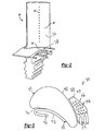
- a turbine blade 20 is illustrated in Figure 2 having a platform 32 and an airfoil 34 extending outwardly away from the platform 32. While the present invention can be described with respect to its application in a turbine blade 20, the invention could also be utilized in a static structure such as a vane 19 ( Figure 1).
- the turbine blade 20 includes a pressure side 36 of the airfoil 34.
- a pressure side cooling circuit exit 38 is formed in the platform 32 on the pressure side 36 of the airfoil 34.
- a rotor cavity 39 is defined below the platform 32.
- the turbine blade 20 further includes a suction side 40 of the airfoil 34 opposite the pressure side 36, as shown in Figure 3.
- Figure 3 is a plan view of the turbine blade 20, schematically showing the location of a pressure side cooling circuit 42 and a suction side cooling circuit 46 which are contained within the platform 32 and lead to a pressure side cooling circuit exit 38 and suction side cooling circuit exit 54 on the upper surface of the platform 32.
- the pressure side cooling circuit 42 further includes a pressure side cooling circuit inlet 44.
- the suction side cooling circuit 46 includes an inlet 50 opposite the exits 54.
- the suction side cooling circuit 46 may further include a plurality of pedestals 56.
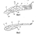
- FIGS 4 and 5 are perspective views of the suction side cooling circuit 46 and the pressure side cooling circuit 42, respectively.
- the cooling circuits 46, 42 in the embodiment shown are metal cores that are separately molded, cast and/or machined to the configurations shown and subsequently insert-cast into the platform 32 ( Figures 2 and 3).
- the cores are hollow in the preferred embodiment described.
- the core includes an outer wall 60 spaced above an inner wall 62.
- the outer wall 60 and inner wall 62 are connected by side walls 64.
- a cooling air path is defined between the outer wall 60, inner wall 62 and side walls 64 from the downwardly directed inlet 50 to the upwardly directed exits 54.
- a plurality of pedestals 56 connect the outer wall 60 and inner wall 62.
- the pedestals 56 increase the structural integrity and stiffness of the cooling circuit 46.
- the pedestals 56 also turbulate the flow and enhance the cooling by increasing the internal heat transfer coefficients.
- the pedestals 56 also provide increased surface area for cooling and provide conduction paths between the outer wall 60 and the inner wall 62 of the cooling circuit 46.
- the exits 54 from the cooling circuit 46 extend upwardly at an angle in order to provide the film coverage on the outer surface of the platform 32 ( Figure 2).
- the film blanket will protect the platform 32 from the hot gas recovery temperatures.
- the core includes an outer wall 66 opposite an inner wall 70 and connected by opposed side walls 68 to define a cooling path from a downwardly directed inlet 44 along a serpentine path to an upwardly directed exit 38.
- the pressure side cooling circuit 42 could optionally include the pedestals similar to those in the suction side cooling circuit 46 of Figure 4.
- the exit 38 on the pressure side cooling circuit 42 is directed upwardly at an angle and is elongated in order to provide film coverage on the outer surface of the platfo rm 32 ( Figure 2).
- cooling air from the rotor cavity 39 passes into the inlets 44, 50 of the cooling circuits 42, 46.
- the cooling air then travels through the cooing circuits 42, 46 in a direction generally parallel to the outer walls 60, 66 and inner walls 70, 62 to cool the platform 32.
- the air then exits the cooling circuits 42, 46 via the exits 38, 54 and forms a film blanket along the exterior surface of the blade platform 32.
- the cooling circuits 42, 46 increase the thermal convective efficiency for increased heat pick-up.
- the internal heat transfer coefficients are increased as the metal temperature is decreased.
- the optional microcircuit pedestals 56 increase the stiffness and resistance to shear by improving rigidity of the turbine assembly and turbulate the cooling air flow.
- the slot exits 38, 54 provide improved film coverage of the platform 32.
- the platform 32 has increased material capability and resistance to creep deformation.
Landscapes
- Engineering & Computer Science (AREA)
- Mechanical Engineering (AREA)
- General Engineering & Computer Science (AREA)
- Chemical & Material Sciences (AREA)
- Combustion & Propulsion (AREA)
- Turbine Rotor Nozzle Sealing (AREA)
Abstract
Description
- The present invention relates generally to gas turbine engines and more particularly to a cooling circuit for a platform of a turbine airfoil.
- Turbine blades in a gas turbine engine extend outwardly from a turbine blade platform. In operation, the turbine blades are routinely exposed to temperatures well above their material limits. In existing engines, air from the compressor section of the turbine engine is used to cool the blade material. This cooling air is fed to the blade through a series of rotor cavities underneath the blade platform. The cooling air is then injected into the hot mainstream flow through openings in the sealing area.
- Without sufficient cooling of the platform, the platform walls may experience creep deformation. High temperature gradients in the platform may result in thermal-mechanical fatigue. Additionally, the high temperatures can cause oxidation of the platforms.
- The present invention provides a cooling circuit for a turbine airfoil platform. The cooling circuit permits higher inlet temperatures than the current airfoil assembly designs.
- In a disclosed embodiment of the present invention, the cooling circuit cools the pressure side of the platform, while another cooling circuit cools the suction side of the platform. In general, the inlet of each cooling circuit receives cooling air from the rotor cavity below the platform. The cooling air flows through each circuit and cools the walls of the platform.
- Optionally, at least the suction side of the cooling circuit includes a plurality of pedestals extending between top and bottom walls of the cooling circuit. The pedestals are positioned inside the circuit to provide structural integrity and stiffness for the platform. The pedestals also turbulate the flow and enhance cooling by increasing the internal heat transfer coefficients. The pedestals also provide increased surface area for cooling and provide conduction paths between the outer and inner wall of the cooling circuit.
- The exit of each cooling circuit drives the cooling air in such a way as to provide the film coverage on the platform. This film blanket of cooling air further protects the platform walls from the hot gas recovery temperatures.
- Other advantages of the present invention can be understood by reference to the following detailed description when considered in connection with the accompanying drawings wherein:
- FIGURE 1 is a schematic of a gas turbine engine incorporating one embodiment of an airfoil assembly of the present invention.
- FIGURE 2 is a turbine blade of Figure 1.
- FIGURE 3 is a plan view of the turbine blade of Figure 2.
- FIGURE 4 is a perspective view of the suction side cooling circuit of Figure 3.
- FIGURE 5 is a perspective view of the pressure side cooling circuit of Figure 3.
- Figure 1 shows a
gas turbine engine 10, such as a gas turbine used for power generation or propulsion, circumferentially disposed about an engine centerline oraxial centerline axis 12. Theengine 10 includes afan 14, acompressor 16, acombustion section 18 and aturbine 11. As is well known, air compressed in thecompressor 16 is mixed with fuel that is burned in thecombustion section 18 and expanded inturbine 11. Theturbine 11 includesrotors 13 and 15 that rotate in response to the expansion, driving thecompressor 16 andfan 14. Theturbine 11 compresses alternating rows ofturbine blades 20 and vanes 19. Figure 1 is a somewhat schematic presentation for illustrative purposes only and is not a limitation on the instant invention, which may be employed on gas turbines for electrical power generation, aircraft, etc. Additionally, there are various types of gas turbine engines, many of which could benefit from the present invention, which is not limited to the design shown. - A
turbine blade 20 is illustrated in Figure 2 having aplatform 32 and anairfoil 34 extending outwardly away from theplatform 32. While the present invention can be described with respect to its application in aturbine blade 20, the invention could also be utilized in a static structure such as a vane 19 (Figure 1). Theturbine blade 20 includes apressure side 36 of theairfoil 34. A pressure sidecooling circuit exit 38 is formed in theplatform 32 on thepressure side 36 of theairfoil 34. A rotor cavity 39 is defined below theplatform 32. - The
turbine blade 20 further includes a suction side 40 of theairfoil 34 opposite thepressure side 36, as shown in Figure 3. Figure 3 is a plan view of theturbine blade 20, schematically showing the location of a pressureside cooling circuit 42 and a suctionside cooling circuit 46 which are contained within theplatform 32 and lead to a pressure sidecooling circuit exit 38 and suction sidecooling circuit exit 54 on the upper surface of theplatform 32. As shown in Figure 3, the pressureside cooling circuit 42 further includes a pressure sidecooling circuit inlet 44. The suctionside cooling circuit 46 includes aninlet 50 opposite theexits 54. The suctionside cooling circuit 46 may further include a plurality ofpedestals 56. - Figures 4 and 5 are perspective views of the suction
side cooling circuit 46 and the pressureside cooling circuit 42, respectively. Thecooling circuits - Referring specifically to the suction
side cooling circuit 46 in Figure 4, the core includes anouter wall 60 spaced above aninner wall 62. Theouter wall 60 andinner wall 62 are connected byside walls 64. A cooling air path is defined between theouter wall 60,inner wall 62 andside walls 64 from the downwardly directedinlet 50 to the upwardly directedexits 54. A plurality ofpedestals 56 connect theouter wall 60 andinner wall 62. Thepedestals 56 increase the structural integrity and stiffness of thecooling circuit 46. Thepedestals 56 also turbulate the flow and enhance the cooling by increasing the internal heat transfer coefficients. Thepedestals 56 also provide increased surface area for cooling and provide conduction paths between theouter wall 60 and theinner wall 62 of thecooling circuit 46. Theexits 54 from thecooling circuit 46 extend upwardly at an angle in order to provide the film coverage on the outer surface of the platform 32 (Figure 2). The film blanket will protect theplatform 32 from the hot gas recovery temperatures. - Referring specifically to the pressure
side cooling circuit 42 in Figure 5, the core includes anouter wall 66 opposite aninner wall 70 and connected byopposed side walls 68 to define a cooling path from a downwardly directedinlet 44 along a serpentine path to an upwardly directedexit 38. Although shown without pedestals, the pressureside cooling circuit 42 could optionally include the pedestals similar to those in the suctionside cooling circuit 46 of Figure 4. Again, theexit 38 on the pressureside cooling circuit 42 is directed upwardly at an angle and is elongated in order to provide film coverage on the outer surface of the platfo rm 32 (Figure 2). - Referring to Figures 2-5, in operation, cooling air from the rotor cavity 39 passes into the
inlets cooling circuits cooing circuits outer walls inner walls platform 32. The air then exits thecooling circuits exits blade platform 32. - The cooling
circuits platform 32. Theplatform 32 has increased material capability and resistance to creep deformation. - In accordance with the provisions of the patent statutes and jurisprudence, exemplary configurations described above are considered to represent a preferred embodiment of the invention. However, it should be noted that the invention can be practiced otherwise than as specifically illustrated and described without departing from its scope.
Claims (18)
- An airfoil assembly comprising:an airfoil (34) having a base end, an outer end, a pressure side (36) and a suction side (40); anda platform (32) connected to the base end of the airfoil, the platform (32) including a cooling circuit (42; 46) having an inlet (44; 50) on the platform (32) and an exit (38; 54) on the platform (32).
- The assembly of claim 1 wherein the cooling circuit is a pressure side cooling circuit (42) on the pressure side (36) of the airfoil (34).
- The assembly of claim 2 further including a suction side cooling circuit (46) on the suction side (40) of the airfoil (34).
- The assembly of claim 1 wherein the cooling circuit (46) is on the suction side (40) of the airfoil (34).
- The assembly of any preceding claim wherein the cooling circuit (46) includes a plurality of pedestals (56).
- The assembly of any preceding claim wherein the cooling circuit includes a hollow metal core (42; 46) integrally cast with the platform (32).
- The assembly of any preceding claim wherein the platform (32) includes an outer surface, the exit (38; 54) formed through the outer surface of the platform (32).
- The assembly of any preceding claim wherein the cooling circuit includes a plurality of exits (54), including the exit.
- The assembly of any preceding claim wherein the cooling circuit (42; 46) includes a passage extending parallel to an upper surface of the platform (32) between the inlet and the exit.
- A cooling circuit (42; 46) for an airfoil platform (32) comprising:an outer wall (66; 60);an inner wall (70; 62) spaced away from the outer wall to define a cooling airflow passage therebetween;a downwardly directed inlet (44; 50) in communication with the cooling airflow passage; andan upwardly directed exit (38; 54) in communication with the cooling airflow passage.
- The assembly of claim 10 wherein the cooling circuit (46) includes a plurality of pedestals (56) extending between the outer wall (10) and the inner wall (62).
- An airfoil platform assembly including the cooling circuit of claim 10 or 11, the assembly further comprising:a platform (32) having an upper surface with a pressure side and a suction side; andthe cooling circuit (42; 46) at least partially within the platform (32), the cooling circuit having the inlet (44; 50) on the platform (32) and the exit (38; 54) through the upper surface of the platform (32).
- The assembly of claim 12 wherein the cooling circuit (42) is on the pressure side of the upper surface of the platform (32).
- The assembly of claim 12 wherein the cooling circuit (46) is on the suction side of the upper surface of the platform (32).
- The assembly of any of claims 12 to 16 wherein the cooling circuit is a hollow metal core (42; 46) integrally cast into the platform (32).
- A method of cooling a turbine airfoil including the steps of:passing a cooling fluid into an inlet (44; 50) in a platform (32) of a turbine airfoil assembly (20);directing the cooling fluid through a cooling circuit (42; 46) through the platform (32); andexhausting the cooling fluid from an exit (38; 54) in the platform (32).
- The method of claim 16 wherein the platform (32) includes an outer surface, the exit (38; 54) extending through the outer surface of the platform (32).
- The method of claim 16 or 17 further including a turbine blade (34) extending outwardly from the outer surface of the platform (32), the method further including the step of passing the cooling fluid out through the exit (38; 54) and then along the outer surface of the platform (32).
Applications Claiming Priority (1)
| Application Number | Priority Date | Filing Date | Title |
|---|---|---|---|
| US11/134,927 US7255536B2 (en) | 2005-05-23 | 2005-05-23 | Turbine airfoil platform cooling circuit |
Publications (3)
| Publication Number | Publication Date |
|---|---|
| EP1726785A2 true EP1726785A2 (en) | 2006-11-29 |
| EP1726785A3 EP1726785A3 (en) | 2009-12-30 |
| EP1726785B1 EP1726785B1 (en) | 2011-07-20 |
Family
ID=36717079
Family Applications (1)
| Application Number | Title | Priority Date | Filing Date |
|---|---|---|---|
| EP06251550A Expired - Lifetime EP1726785B1 (en) | 2005-05-23 | 2006-03-23 | Turbine airfoil platform cooling circuit |
Country Status (7)
| Country | Link |
|---|---|
| US (1) | US7255536B2 (en) |
| EP (1) | EP1726785B1 (en) |
| JP (1) | JP2006329185A (en) |
| KR (1) | KR20060121092A (en) |
| CN (1) | CN1869410A (en) |
| SG (1) | SG127789A1 (en) |
| TW (1) | TW200641239A (en) |
Cited By (10)
| Publication number | Priority date | Publication date | Assignee | Title |
|---|---|---|---|---|
| CH700320A1 (en) * | 2009-01-30 | 2010-07-30 | Alstom Technology Ltd | Method for producing a component of a gas turbine. |
| EP1813776A3 (en) * | 2006-01-31 | 2011-04-06 | United Technologies Corporation | Microcircuits for cooling of small turbine engine blades |
| EP2019187A3 (en) * | 2007-07-24 | 2011-10-19 | United Technologies Corporation | Apparatus and methods for providing vane platform cooling |
| US8167559B2 (en) | 2009-03-03 | 2012-05-01 | Siemens Energy, Inc. | Turbine vane for a gas turbine engine having serpentine cooling channels within the outer wall |
| EP2538025A1 (en) * | 2011-06-20 | 2012-12-26 | General Electric Company | Hot gas path component and corresponding method of forming a component |
| EP2469034A3 (en) * | 2010-12-22 | 2014-01-01 | United Technologies Corporation | Turbine stator vane having a platform with a cooling circuit and corresponding manufacturing method |
| EP2325439A3 (en) * | 2009-11-23 | 2014-04-30 | United Technologies Corporation | Turbine airfoil platform cooling core |
| US9062561B2 (en) | 2010-09-29 | 2015-06-23 | Rolls-Royce Plc | Endwall component for a turbine stage of a gas turbine engine |
| EP3208424A1 (en) * | 2016-02-17 | 2017-08-23 | United Technologies Corporation | Gas turbine engine component having vascular engineered lattice structure |
| US10774653B2 (en) | 2018-12-11 | 2020-09-15 | Raytheon Technologies Corporation | Composite gas turbine engine component with lattice structure |
Families Citing this family (50)
| Publication number | Priority date | Publication date | Assignee | Title |
|---|---|---|---|---|
| US8408874B2 (en) * | 2008-04-11 | 2013-04-02 | United Technologies Corporation | Platformless turbine blade |
| US8206114B2 (en) * | 2008-04-29 | 2012-06-26 | United Technologies Corporation | Gas turbine engine systems involving turbine blade platforms with cooling holes |
| US8157527B2 (en) * | 2008-07-03 | 2012-04-17 | United Technologies Corporation | Airfoil with tapered radial cooling passage |
| US8348614B2 (en) * | 2008-07-14 | 2013-01-08 | United Technologies Corporation | Coolable airfoil trailing edge passage |
| US8240987B2 (en) * | 2008-08-15 | 2012-08-14 | United Technologies Corp. | Gas turbine engine systems involving baffle assemblies |
| US8572844B2 (en) * | 2008-08-29 | 2013-11-05 | United Technologies Corporation | Airfoil with leading edge cooling passage |
| US8303252B2 (en) * | 2008-10-16 | 2012-11-06 | United Technologies Corporation | Airfoil with cooling passage providing variable heat transfer rate |
| US8109725B2 (en) | 2008-12-15 | 2012-02-07 | United Technologies Corporation | Airfoil with wrapped leading edge cooling passage |
| US8523527B2 (en) * | 2010-03-10 | 2013-09-03 | General Electric Company | Apparatus for cooling a platform of a turbine component |
| US8517680B1 (en) * | 2010-04-23 | 2013-08-27 | Florida Turbine Technologies, Inc. | Turbine blade with platform cooling |
| US8647064B2 (en) | 2010-08-09 | 2014-02-11 | General Electric Company | Bucket assembly cooling apparatus and method for forming the bucket assembly |
| US9416666B2 (en) | 2010-09-09 | 2016-08-16 | General Electric Company | Turbine blade platform cooling systems |
| US8840369B2 (en) * | 2010-09-30 | 2014-09-23 | General Electric Company | Apparatus and methods for cooling platform regions of turbine rotor blades |
| US8814517B2 (en) * | 2010-09-30 | 2014-08-26 | General Electric Company | Apparatus and methods for cooling platform regions of turbine rotor blades |
| US8851846B2 (en) * | 2010-09-30 | 2014-10-07 | General Electric Company | Apparatus and methods for cooling platform regions of turbine rotor blades |
| US8851845B2 (en) | 2010-11-17 | 2014-10-07 | General Electric Company | Turbomachine vane and method of cooling a turbomachine vane |
| US9447691B2 (en) * | 2011-08-22 | 2016-09-20 | General Electric Company | Bucket assembly treating apparatus and method for treating bucket assembly |
| US8840370B2 (en) | 2011-11-04 | 2014-09-23 | General Electric Company | Bucket assembly for turbine system |
| US8845289B2 (en) | 2011-11-04 | 2014-09-30 | General Electric Company | Bucket assembly for turbine system |
| US8858160B2 (en) | 2011-11-04 | 2014-10-14 | General Electric Company | Bucket assembly for turbine system |
| US8870525B2 (en) | 2011-11-04 | 2014-10-28 | General Electric Company | Bucket assembly for turbine system |
| US9022735B2 (en) * | 2011-11-08 | 2015-05-05 | General Electric Company | Turbomachine component and method of connecting cooling circuits of a turbomachine component |
| US8905714B2 (en) * | 2011-12-30 | 2014-12-09 | General Electric Company | Turbine rotor blade platform cooling |
| US9109454B2 (en) | 2012-03-01 | 2015-08-18 | General Electric Company | Turbine bucket with pressure side cooling |
| US8974182B2 (en) | 2012-03-01 | 2015-03-10 | General Electric Company | Turbine bucket with a core cavity having a contoured turn |
| US9127561B2 (en) | 2012-03-01 | 2015-09-08 | General Electric Company | Turbine bucket with contoured internal rib |
| BR112014031269A2 (en) | 2012-06-15 | 2017-08-08 | Gen Electric | turbine airfoil apparatus and method of forming a cooling orifice pattern. |
| US9021816B2 (en) | 2012-07-02 | 2015-05-05 | United Technologies Corporation | Gas turbine engine turbine vane platform core |
| US10533453B2 (en) * | 2013-08-05 | 2020-01-14 | United Technologies Corporation | Engine component having platform with passageway |
| WO2015080783A2 (en) | 2013-09-19 | 2015-06-04 | United Technologies Corporation | Gas turbine engine airfoil having serpentine fed platform cooling passage |
| US9551226B2 (en) | 2013-10-23 | 2017-01-24 | General Electric Company | Turbine bucket with endwall contour and airfoil profile |
| US9347320B2 (en) | 2013-10-23 | 2016-05-24 | General Electric Company | Turbine bucket profile yielding improved throat |
| US9638041B2 (en) | 2013-10-23 | 2017-05-02 | General Electric Company | Turbine bucket having non-axisymmetric base contour |
| US9797258B2 (en) | 2013-10-23 | 2017-10-24 | General Electric Company | Turbine bucket including cooling passage with turn |
| US9528379B2 (en) | 2013-10-23 | 2016-12-27 | General Electric Company | Turbine bucket having serpentine core |
| US9376927B2 (en) | 2013-10-23 | 2016-06-28 | General Electric Company | Turbine nozzle having non-axisymmetric endwall contour (EWC) |
| US9670784B2 (en) * | 2013-10-23 | 2017-06-06 | General Electric Company | Turbine bucket base having serpentine cooling passage with leading edge cooling |
| US10001018B2 (en) | 2013-10-25 | 2018-06-19 | General Electric Company | Hot gas path component with impingement and pedestal cooling |
| US9982542B2 (en) | 2014-07-21 | 2018-05-29 | United Technologies Corporation | Airfoil platform impingement cooling holes |
| US10167726B2 (en) | 2014-09-11 | 2019-01-01 | United Technologies Corporation | Component core with shaped edges |
| US10465523B2 (en) | 2014-10-17 | 2019-11-05 | United Technologies Corporation | Gas turbine component with platform cooling |
| US10280761B2 (en) * | 2014-10-29 | 2019-05-07 | United Technologies Corporation | Three dimensional airfoil micro-core cooling chamber |
| US10041357B2 (en) | 2015-01-20 | 2018-08-07 | United Technologies Corporation | Cored airfoil platform with outlet slots |
| US10030523B2 (en) * | 2015-02-13 | 2018-07-24 | United Technologies Corporation | Article having cooling passage with undulating profile |
| US10107108B2 (en) | 2015-04-29 | 2018-10-23 | General Electric Company | Rotor blade having a flared tip |
| US10378379B2 (en) | 2015-08-27 | 2019-08-13 | General Electric Company | Gas turbine engine cooling air manifolds with spoolies |
| US10060288B2 (en) * | 2015-10-09 | 2018-08-28 | United Technologies Corporation | Multi-flow cooling passage chamber for gas turbine engine |
| US10358928B2 (en) * | 2016-05-10 | 2019-07-23 | General Electric Company | Airfoil with cooling circuit |
| EP3287596A1 (en) * | 2016-08-25 | 2018-02-28 | Siemens Aktiengesellschaft | A platform cooling device for a blade of a turbomachine and a turbomachine arrangement |
| US12497897B1 (en) | 2024-09-03 | 2025-12-16 | Ge Infrastructure Technology Llc | Airfoil component for turbomachine component with platform cooling using airfoil coolant |
Citations (1)
| Publication number | Priority date | Publication date | Assignee | Title |
|---|---|---|---|---|
| US6065931A (en) | 1998-03-05 | 2000-05-23 | Mitsubishi Heavy Industries, Ltd. | Gas turbine moving blade |
Family Cites Families (23)
| Publication number | Priority date | Publication date | Assignee | Title |
|---|---|---|---|---|
| US2844855A (en) * | 1953-11-05 | 1958-07-29 | Bristol Aero Engines Ltd | Method of producing castings with one or more internal passages |
| US3800864A (en) * | 1972-09-05 | 1974-04-02 | Gen Electric | Pin-fin cooling system |
| US4017213A (en) * | 1975-10-14 | 1977-04-12 | United Technologies Corporation | Turbomachinery vane or blade with cooled platforms |
| GB1553701A (en) * | 1976-05-14 | 1979-09-26 | Rolls Royce | Nozzle guide vane for a gas turbine engine |
| US4353679A (en) * | 1976-07-29 | 1982-10-12 | General Electric Company | Fluid-cooled element |
| US5197852A (en) * | 1990-05-31 | 1993-03-30 | General Electric Company | Nozzle band overhang cooling |
| US5405242A (en) * | 1990-07-09 | 1995-04-11 | United Technologies Corporation | Cooled vane |
| US5390774A (en) * | 1993-09-27 | 1995-02-21 | General Motors Corporation | Electromagnetic clutch with improved guidance and retention |
| DE69505407T2 (en) * | 1994-08-24 | 1999-05-27 | Westinghouse Electric Corp., Pittsburgh, Pa. | GAS TURBINE BLADE WITH COOLED PLATFORM |
| KR100364183B1 (en) * | 1994-10-31 | 2003-02-19 | 웨스팅하우스 일렉트릭 코포레이션 | Gas turbine blade with a cooled platform |
| FR2758855B1 (en) * | 1997-01-30 | 1999-02-26 | Snecma | VENTILATION SYSTEM FOR MOBILE VANE PLATFORMS |
| JP3758792B2 (en) * | 1997-02-25 | 2006-03-22 | 三菱重工業株式会社 | Gas turbine rotor platform cooling mechanism |
| US6092983A (en) * | 1997-05-01 | 2000-07-25 | Mitsubishi Heavy Industries, Ltd. | Gas turbine cooling stationary blade |
| CA2262064C (en) * | 1998-02-23 | 2002-09-03 | Mitsubishi Heavy Industries, Ltd. | Gas turbine moving blade platform |
| US6190130B1 (en) * | 1998-03-03 | 2001-02-20 | Mitsubishi Heavy Industries, Ltd. | Gas turbine moving blade platform |
| US6210111B1 (en) * | 1998-12-21 | 2001-04-03 | United Technologies Corporation | Turbine blade with platform cooling |
| KR100694370B1 (en) * | 1999-05-14 | 2007-03-12 | 제너럴 일렉트릭 캄파니 | Apparatus for controlling temperature mismatch in the inner and outer bands of turbine nozzles and a method of reducing the temperature difference between the wall and cover of the inner or outer bands |
| US6254333B1 (en) * | 1999-08-02 | 2001-07-03 | United Technologies Corporation | Method for forming a cooling passage and for cooling a turbine section of a rotary machine |
| US6390774B1 (en) | 2000-02-02 | 2002-05-21 | General Electric Company | Gas turbine bucket cooling circuit and related process |
| US6478540B2 (en) * | 2000-12-19 | 2002-11-12 | General Electric Company | Bucket platform cooling scheme and related method |
| US6450759B1 (en) * | 2001-02-16 | 2002-09-17 | General Electric Company | Gas turbine nozzle vane insert and methods of installation |
| US6945749B2 (en) * | 2003-09-12 | 2005-09-20 | Siemens Westinghouse Power Corporation | Turbine blade platform cooling system |
| US7097424B2 (en) * | 2004-02-03 | 2006-08-29 | United Technologies Corporation | Micro-circuit platform |
-
2005
- 2005-05-23 US US11/134,927 patent/US7255536B2/en not_active Expired - Lifetime
-
2006
- 2006-02-14 TW TW095104908A patent/TW200641239A/en unknown
- 2006-03-07 KR KR1020060021132A patent/KR20060121092A/en not_active Abandoned
- 2006-03-14 SG SG200601656A patent/SG127789A1/en unknown
- 2006-03-17 JP JP2006074295A patent/JP2006329185A/en active Pending
- 2006-03-22 CN CNA2006100682453A patent/CN1869410A/en active Pending
- 2006-03-23 EP EP06251550A patent/EP1726785B1/en not_active Expired - Lifetime
Patent Citations (1)
| Publication number | Priority date | Publication date | Assignee | Title |
|---|---|---|---|---|
| US6065931A (en) | 1998-03-05 | 2000-05-23 | Mitsubishi Heavy Industries, Ltd. | Gas turbine moving blade |
Cited By (16)
| Publication number | Priority date | Publication date | Assignee | Title |
|---|---|---|---|---|
| EP1813776A3 (en) * | 2006-01-31 | 2011-04-06 | United Technologies Corporation | Microcircuits for cooling of small turbine engine blades |
| US7988418B2 (en) | 2006-01-31 | 2011-08-02 | United Technologies Corporation | Microcircuits for small engines |
| EP2019187A3 (en) * | 2007-07-24 | 2011-10-19 | United Technologies Corporation | Apparatus and methods for providing vane platform cooling |
| CH700320A1 (en) * | 2009-01-30 | 2010-07-30 | Alstom Technology Ltd | Method for producing a component of a gas turbine. |
| WO2010086402A3 (en) * | 2009-01-30 | 2010-10-21 | Alstom Technology Ltd. | Method for producing a component of a gas turbine |
| US8167559B2 (en) | 2009-03-03 | 2012-05-01 | Siemens Energy, Inc. | Turbine vane for a gas turbine engine having serpentine cooling channels within the outer wall |
| EP2325439A3 (en) * | 2009-11-23 | 2014-04-30 | United Technologies Corporation | Turbine airfoil platform cooling core |
| US9062561B2 (en) | 2010-09-29 | 2015-06-23 | Rolls-Royce Plc | Endwall component for a turbine stage of a gas turbine engine |
| EP2469034A3 (en) * | 2010-12-22 | 2014-01-01 | United Technologies Corporation | Turbine stator vane having a platform with a cooling circuit and corresponding manufacturing method |
| US8714909B2 (en) | 2010-12-22 | 2014-05-06 | United Technologies Corporation | Platform with cooling circuit |
| EP2538025A1 (en) * | 2011-06-20 | 2012-12-26 | General Electric Company | Hot gas path component and corresponding method of forming a component |
| US8915712B2 (en) | 2011-06-20 | 2014-12-23 | General Electric Company | Hot gas path component |
| EP3208424A1 (en) * | 2016-02-17 | 2017-08-23 | United Technologies Corporation | Gas turbine engine component having vascular engineered lattice structure |
| US10221694B2 (en) | 2016-02-17 | 2019-03-05 | United Technologies Corporation | Gas turbine engine component having vascular engineered lattice structure |
| US10774653B2 (en) | 2018-12-11 | 2020-09-15 | Raytheon Technologies Corporation | Composite gas turbine engine component with lattice structure |
| US11168568B2 (en) | 2018-12-11 | 2021-11-09 | Raytheon Technologies Corporation | Composite gas turbine engine component with lattice |
Also Published As
| Publication number | Publication date |
|---|---|
| EP1726785A3 (en) | 2009-12-30 |
| TW200641239A (en) | 2006-12-01 |
| KR20060121092A (en) | 2006-11-28 |
| US20060263221A1 (en) | 2006-11-23 |
| EP1726785B1 (en) | 2011-07-20 |
| SG127789A1 (en) | 2006-12-29 |
| CN1869410A (en) | 2006-11-29 |
| US7255536B2 (en) | 2007-08-14 |
| JP2006329185A (en) | 2006-12-07 |
Similar Documents
| Publication | Publication Date | Title |
|---|---|---|
| EP1726785B1 (en) | Turbine airfoil platform cooling circuit | |
| CA2672806C (en) | Shrouded rotor blade with outer plenum and method of fabricating the same | |
| EP1944467B1 (en) | Cooling circuit flow path for a turbine section airfoil | |
| US7513738B2 (en) | Methods and apparatus for cooling gas turbine rotor blades | |
| US7632062B2 (en) | Turbine rotor blades | |
| US6471479B2 (en) | Turbine airfoil with single aft flowing three pass serpentine cooling circuit | |
| EP0852285B2 (en) | Turbulator configuration for cooling passages of rotor blade in a gas turbine engine | |
| EP1956192B1 (en) | Gas turbine engine component cooling scheme | |
| EP2374997B1 (en) | Component for a gas turbine engine | |
| JP2006083859A (en) | Apparatus and method for cooling turbine blade platform | |
| EP1808574B1 (en) | Turbine engine with improved cooling | |
| CA2861175C (en) | Internally cooled airfoil | |
| CN107091122B (en) | Turbine engine airfoil with cooling | |
| EP1362982B1 (en) | Turbine airfoil with single aft flowing three pass serpentine cooling circuit | |
| EP3192972B1 (en) | Flow exchange baffle insert for a gas turbine engine component | |
| EP4613980A1 (en) | Turbine vane with leading edge cooling | |
| EP3203026B1 (en) | Gas turbine blade with pedestal array | |
| KR20240157715A (en) | Turbine blades and gas turbines | |
| EP3121377A1 (en) | Turbine rotors including turbine blades having turbulator cooled tip pockets | |
| JPS59196904A (en) | Stator blade of gas turbine |
Legal Events
| Date | Code | Title | Description |
|---|---|---|---|
| PUAI | Public reference made under article 153(3) epc to a published international application that has entered the european phase |
Free format text: ORIGINAL CODE: 0009012 |
|
| AK | Designated contracting states |
Kind code of ref document: A2 Designated state(s): AT BE BG CH CY CZ DE DK EE ES FI FR GB GR HU IE IS IT LI LT LU LV MC NL PL PT RO SE SI SK TR |
|
| AX | Request for extension of the european patent |
Extension state: AL BA HR MK YU |
|
| PUAL | Search report despatched |
Free format text: ORIGINAL CODE: 0009013 |
|
| AK | Designated contracting states |
Kind code of ref document: A3 Designated state(s): AT BE BG CH CY CZ DE DK EE ES FI FR GB GR HU IE IS IT LI LT LU LV MC NL PL PT RO SE SI SK TR |
|
| AX | Request for extension of the european patent |
Extension state: AL BA HR MK YU |
|
| 17P | Request for examination filed |
Effective date: 20100308 |
|
| 17Q | First examination report despatched |
Effective date: 20100510 |
|
| AKX | Designation fees paid |
Designated state(s): DE FR GB IT |
|
| GRAP | Despatch of communication of intention to grant a patent |
Free format text: ORIGINAL CODE: EPIDOSNIGR1 |
|
| GRAS | Grant fee paid |
Free format text: ORIGINAL CODE: EPIDOSNIGR3 |
|
| GRAA | (expected) grant |
Free format text: ORIGINAL CODE: 0009210 |
|
| AK | Designated contracting states |
Kind code of ref document: B1 Designated state(s): DE FR GB IT |
|
| REG | Reference to a national code |
Ref country code: GB Ref legal event code: FG4D |
|
| REG | Reference to a national code |
Ref country code: DE Ref legal event code: R096 Ref document number: 602006023148 Country of ref document: DE Effective date: 20110915 |
|
| PLBE | No opposition filed within time limit |
Free format text: ORIGINAL CODE: 0009261 |
|
| STAA | Information on the status of an ep patent application or granted ep patent |
Free format text: STATUS: NO OPPOSITION FILED WITHIN TIME LIMIT |
|
| PG25 | Lapsed in a contracting state [announced via postgrant information from national office to epo] |
Ref country code: IT Free format text: LAPSE BECAUSE OF FAILURE TO SUBMIT A TRANSLATION OF THE DESCRIPTION OR TO PAY THE FEE WITHIN THE PRESCRIBED TIME-LIMIT Effective date: 20110720 |
|
| 26N | No opposition filed |
Effective date: 20120423 |
|
| REG | Reference to a national code |
Ref country code: DE Ref legal event code: R097 Ref document number: 602006023148 Country of ref document: DE Effective date: 20120423 |
|
| REG | Reference to a national code |
Ref country code: FR Ref legal event code: ST Effective date: 20121130 |
|
| PG25 | Lapsed in a contracting state [announced via postgrant information from national office to epo] |
Ref country code: FR Free format text: LAPSE BECAUSE OF NON-PAYMENT OF DUE FEES Effective date: 20120402 |
|
| REG | Reference to a national code |
Ref country code: DE Ref legal event code: R082 Ref document number: 602006023148 Country of ref document: DE Representative=s name: SCHMITT-NILSON SCHRAUD WAIBEL WOHLFROM PATENTA, DE |
|
| REG | Reference to a national code |
Ref country code: DE Ref legal event code: R081 Ref document number: 602006023148 Country of ref document: DE Owner name: RAYTHEON TECHNOLOGIES CORPORATION (N.D.GES.D.S, US Free format text: FORMER OWNER: UNITED TECHNOLOGIES CORPORATION, HARTFORD, CONN., US Ref country code: DE Ref legal event code: R081 Ref document number: 602006023148 Country of ref document: DE Owner name: RTX CORPORATION (N.D.GES.D. STAATES DELAWARE),, US Free format text: FORMER OWNER: UNITED TECHNOLOGIES CORPORATION, HARTFORD, CONN., US |
|
| P01 | Opt-out of the competence of the unified patent court (upc) registered |
Effective date: 20230519 |
|
| PGFP | Annual fee paid to national office [announced via postgrant information from national office to epo] |
Ref country code: DE Payment date: 20250218 Year of fee payment: 20 |
|
| PGFP | Annual fee paid to national office [announced via postgrant information from national office to epo] |
Ref country code: GB Payment date: 20250221 Year of fee payment: 20 |
|
| REG | Reference to a national code |
Ref country code: DE Ref legal event code: R081 Ref document number: 602006023148 Country of ref document: DE Owner name: RTX CORPORATION (N.D.GES.D. STAATES DELAWARE),, US Free format text: FORMER OWNER: RAYTHEON TECHNOLOGIES CORPORATION (N.D.GES.D.STAATES DELAWARE), ARLINGTON, VA, US |
|
| REG | Reference to a national code |
Ref country code: DE Ref legal event code: R071 Ref document number: 602006023148 Country of ref document: DE |
|
| REG | Reference to a national code |
Ref country code: GB Ref legal event code: PE20 Expiry date: 20260322 |