EP1726696A2 - Selvage device in loom - Google Patents
Selvage device in loom Download PDFInfo
- Publication number
- EP1726696A2 EP1726696A2 EP06006887A EP06006887A EP1726696A2 EP 1726696 A2 EP1726696 A2 EP 1726696A2 EP 06006887 A EP06006887 A EP 06006887A EP 06006887 A EP06006887 A EP 06006887A EP 1726696 A2 EP1726696 A2 EP 1726696A2
- Authority
- EP
- European Patent Office
- Prior art keywords
- selvage
- yarns
- rotary member
- guide
- pair
- Prior art date
- Legal status (The legal status is an assumption and is not a legal conclusion. Google has not performed a legal analysis and makes no representation as to the accuracy of the status listed.)
- Withdrawn
Links
Images

Classifications
-
- D—TEXTILES; PAPER
- D03—WEAVING
- D03C—SHEDDING MECHANISMS; PATTERN CARDS OR CHAINS; PUNCHING OF CARDS; DESIGNING PATTERNS
- D03C7/00—Leno or similar shedding mechanisms
- D03C7/08—Devices for twisting warp threads repeatedly in the same direction
Definitions
- the present invention relates to selvage devices in looms, and particularly, to a selvage device in a loom, which rotates a rotary member having a pair of guides that guides selvage yarns so as to allow the selvage yarns to perform a shedding motion.
- JP11-501999T Japanese Translation Patent Publication No. 11-501999
- JP2000-170052A Japanese Unexamined Patent Application Publication No. 2000- 170052
- JP11-501999T Japanese Translation Patent Publication No. 11-501999
- JP2000-170052A Japanese Unexamined Patent Application Publication No. 2000- 170052
- JP11-501999T Japanese Translation Patent Publication No. 11-501999
- JP2000-170052A Japanese Unexamined Patent Application Publication No. 2000- 170052
- the selvage yarns twist around each other at the upstream side of the arms (i.e. closer towards the let-off side of the selvage yarns) in response to the rotation of the arms.
- the number of twists between the selvage yarns increases in proportion to the number of rotations of the arms. This means that if the yarns are not untwisted, the number of twists becomes too large to an extent that the yarns may break. For this reason, when performing a weaving operation, it is necessary to continuously untwist these selvage yarns.
- a selvage operation in the selvage device is implemented by rotating the arms in the reverse direction after the arms are rotated in one direction for a predetermined number of turns.
- the pair of arms is rotated in the reverse direction so as to untwist the selvage yarns from each other.
- the selvage yarns still twist around each other at the upstream side in response to the predetermined number of rotations of the arms. If the selvage yarns are not strong, such twisting may increase the possibility of yarn breakages. For this reason, the types of selvage yarns that can be used in the selvage device of JP11-501999T are limited. Moreover, since the arms used for the selvage operation are reversed after every predetermined number of rotations, the finished selvage edges of the woven cloth may be uneven, which may impair the appearance of the finished product.
- JP2000-170052A discloses an example of a selvage device provided with an untwisting mechanism for untwisting the selvage yarns. Such a mechanism is disposed at an upstream side in the traveling direction of the selvage yarns.
- the selvage device of this type mainly includes a selvage shedding mechanism that moves the selvage yarns in a shedding motion, and the above-referenced untwisting mechanism that is disposed upstream of the selvage shedding mechanism.
- the selvage shedding mechanism includes a guide unit having a pair of guide holes at opposite ends thereof for guiding selvage yarns.
- the guide unit is rotated with a driving shaft, which is driven by a main motor of the loom, so as to allow the selvage yarns to perform a shedding motion.
- the untwisting mechanism includes a rotary plate having a pair of yarn feeders disposed thereon.
- the rotary plate is provided with guide holes for guiding the selvage yarns fed out from the yarn feeders. Accordingly, even if the selvage yarns twist around each other at the upstream side of the guide unit due to the rotation of the guide unit, the untwisting mechanism allows the twisted selvage yarns to revolve in response to the rotating guide unit so that these yarns are untwisted from each other.
- the selvage shedding mechanism applies the main motor of the loom as a driving source, such that the guide unit is rotated continuously at a substantially constant speed. For this reason, the dimension of the shed between the selvage yarns changes continuously at high speed, which means that a period in which the shed is at or close to its maximum dimension is extremely short. Therefore, in the selvage device according to JP2000-170052A , the guide holes must be separated from each other by a large distance in order to attain a required shed dimension in a weft insertion period. In other words, the guide unit must be increased in size. As a result, this disadvantageously leads to an increase in the size of the selvage shedding mechanism.
- a selvage device for a loom has a rotary member provided with guides for guiding selvage yarns, and rotates the rotary member to move the selvage yarns in a shedding motion.
- the selvage device is characterized by including a selvage shedding mechanism having the rotary member and a designated driving motor that rotates the rotary member unidirectionally in an intermittent fashion; and a selvage feeding mechanism disposed upstream of the selvage shedding mechanism in a traveling direction of the selvage yarns.
- the selvage feeding mechanism includes a guide unit having a pair of guide portions for guiding the selvage yarns respectively fed from a pair of yarn feeders; and a rotating unit supporting the guide unit and rotated continuously in the same rotational direction as the rotary member.
- the guide portions revolve in response to the rotation of the rotating unit, such that sections of the selvage yarns extending from the yarn feeders to the corresponding guide portions revolve without intercrossing each other.
- the selvage feeding mechanism may be provided with a designated driving motor that rotates the rotating unit.
- the selvage shedding mechanism is provided with a designated driving motor, which is independent of a main motor of the loom.
- the driving motor intermittently rotates the rotary member, such as an arm, which guides a pair of selvage yarns. Consequently, for a desired time within a weft insertion period, the rotary member can be kept in position (rotational phase) so that the shed between the selvage yarns is maintained at or close to its maximum dimension. Therefore, a required shed dimension for a weft insertion period is sufficiently attained without having to increase the distance between the guides for guiding the selvage yarns and also without having to increase the size of the rotary member.
- an untwisting mechanism i.e. the selvage feeding mechanism
- Such an untwisting mechanism untwists the selvage yarns from each other by revolving the guide unit instead of rotating the rotary member in the reverse direction every time the rotary member is rotated for a predetermined number of turns as in the related art.
- This prevents the selvage yarns from twisting around each other multiple times at the upstream side of the selvage shedding mechanism. Accordingly, this prevents uneven selvage edges of woven cloth caused by the reverse rotation of the rotary member, and also prevents, for example, breakage of selvage yarns, which may be caused by the twisting of the selvage yarns.
- the selvage feeding mechanism with a designated driving motor for driving the rotating unit, a drive transmission mechanism between a main motor of the loom and the selvage feeding mechanism can be omitted.
- This contributes to a simplified overall structure of the loom.
- the unitization of the selvage device simplifies the mounting process of the selvage device to a loom, and also contributes to an easier position adjustment of the selvage device with respect to the loom.
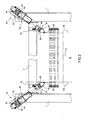
- Figs. 1 to 4 illustrate a selvage device 10 according to a first embodiment of the present invention.
- the selvedge device 10 mainly includes a pair of selvage shedding mechanisms 20 and a pair of selvage feeding mechanisms 30.
- a beam 3 extending between opposite side frames 1, 1 of a loom supports the selvage shedding mechanisms 20 respectively with, for example, a pair of supporting blocks 5.
- Each selvage shedding mechanism 20 is positioned outside a warp array T formed of a plurality of warp yarns.
- the selvage feeding mechanisms 30 are supported respectively by the opposite side frames 1, 1 with, for example, a pair of supporting blocks 7.
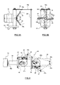
- the selvage shedding mechanism 20 mainly includes a designated driving motor 24 functioning as a driving source, and an arm 26 attached to an output shaft 24a of the driving motor 24 and functioning as a rotary member according to the present invention.
- the driving motor 24 is attached to a bracket 22, such that the selvage shedding mechanism 20 is supported by the corresponding supporting block 5 on the beam 3 via a stay 21 and the bracket 22.
- the supporting block 5 is attached to the beam 3 in an adjustable fashion in the longitudinal direction of the beam 3. Consequently, by adjusting the position of the supporting block 5, the selvage shedding mechanism 20 can be positionally adjusted in the width direction of the loom (that is, in the horizontal direction in Fig. 2).
- the output shaft 24a of the driving motor 24 is hollow, such that two selvage yarns ST, ST from the corresponding selvage feeding mechanism 30 extend through the interior of the output shaft 24a.
- an end of the output shaft 24a proximate to a cloth fell CF i.e. the downstream side of the output shaft 24a in the traveling direction of the selvage yarns ST, ST
- Opposite ends of the arm 26 are respectively provided with selvage guides 26a, 26a having guide holes.
- the selvage guides 26a, 26a are separate components from the arm 26 and are mounted to the arm 26 to function as guides provided in the rotary member according to the present invention.
- these selvage guides 26a, 26a may be omitted.
- the guides in the rotary member may be defined by guide holes provided directly at the opposite ends of the arm 26, such that the selvage yarns ST, ST extend respectively through these guide holes.
- the arm 26 functioning as the rotary member does not necessarily have to be formed of a single-piece material.
- the rotary member may alternatively be defined by a pair of arms attached to the output shaft 24a.
- the driving motor 24 for the selvage shedding mechanism 20 rotates intermittently at a predetermined timing in each weaving cycle. For example, the driving motor 24 stops at a rotational phase at which a shed formed between the two selvage yarns ST, ST reaches its maximum dimension; rotates by 180° at a predetermined timing within a weaving cycle (for example, a timing set in correspondence to an end timing of weft insertion); and then stops again. Consequently, the shed formed between the selvage yarns ST, ST is temporarily closed between a point where a weft yarn is inserted and a point of the rotation process. The shed is then formed again so that the next weft yarn can be inserted.
- a predetermined timing within a weaving cycle for example, a timing set in correspondence to an end timing of weft insertion
- the driving motor 24 for the selvage shedding mechanism 20 is driven intermittently in the following driving pattern: the driving motor 24 is rotated by 180° within a period extending from the predetermined timing to a point at which the subsequent weft yarn passes through the shed formed between the selvage yarns ST, ST, and is stopped until the next predetermined timing.
- the driving operation of the driving motor 24 does not necessarily have to be implemented by alternating the rotating and stopping processes as described above.
- the driving motor 24 may be driven by alternating between low-speed rotation and high-speed rotation modes.
- the driving motor 24 may be switched to a low-speed rotation mode at the rotational phase at which the shed reaches its maximum dimension.
- this low-speed rotation mode the shed is maintained at a required dimension or more over a predetermined period of time.
- the driving motor 24 may be switched back to the high-speed rotation mode.
- the selvage shedding mechanism 20 is provided with a detector segment 28 for detecting breakage of the selvage yarns ST, ST.
- the detector segment 28 is disposed on the end of the output shaft 24a proximate to the cloth fell CF and is positioned near a side of the arm 26 most distant from the cloth fell CF.
- the detector segment 28 is formed of a thin-plate-like material having elasticity and has a pair of cutouts 28a at opposite ends thereof for hooking the selvage yarns ST, ST, respectively. As indicated by a solid line in Fig. 3A, the detector segment 28 is normally in a bent state due to the tension of the selvage yarns ST, ST.
- the detector segment 28 becomes released from the tension of the selvage yarns ST, ST, whereby the detector segment 28 is displaced to a position indicated by a dotted line due to its own elasticity.
- the breakage of the selvage yarns ST, ST can be detected.
- the selvage shedding mechanism 20 is also provided with a guide 29 for regulating the lateral positioning of the selvage yarns ST, ST extending from the selvage guides 26a, 26a of the arm 26.
- the guide 29 is substantially U-shaped and extends in the vertical direction.
- the guide 29 is supported by the bracket 22 with a stay 29a disposed therebetween. The guide 29 regulates the selvage yarns ST, ST positionally in the lateral direction when the arm 26 is rotating.
- the guide 29 allows each selvage yarn ST to have a small angle with respect to the shifting direction of the reed 9 so as to reduce friction between the selvage yarn ST and the dents in the reed 9.
- the selvage feeding mechanism 30 mainly includes a yarn feeder element 40 and a driver element 50.
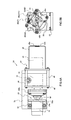
- Figs. 5A and 5B show a state where the yarn feeder element 40 is rotated from the state shown in Figs. 1 and 4, such that a rotary guide member 45, which will be described below, is set in a substantially horizontal state.
- the selvage feeding mechanism 30 is provided with a designated driving motor 52 functioning as a driving source.
- the driving motor 52 is included in the driver element 50.
- the driver element 50 is supported by the corresponding side frame 1 by being linked with a bracket 53, a base plate 51, and the corresponding supporting block 7 attached to the side frame 1.
- the driving motor 52 is supported in a manner such that an output shaft 52a thereof extends through a first stay portion 53a of the bracket 53. Furthermore, the bracket 53 has a second stay portion 53b, which supports a shaft coupling 55 with, for example, a bearing, not shown. One end of the shaft coupling 55 is attached to the output shaft 52a of the driving motor 52 in a relatively non-rotatable fashion. The other end of the shaft coupling 55 is fixedly attached to the yarn feeder element 40. Accordingly, the yarn feeder element 40 is rotatably supported by the bracket 53 via the shaft coupling 55, and is linked with the output shaft 52a of the driving motor 52 via the shaft coupling 55.
- the driving motor 52 is driven in a manner such that the output shaft 52a makes one continuous rotation every time the arm 26 of the corresponding selvage shedding mechanism 20 makes one rotation, or in other words, the output shaft 52a makes one continuous rotation for every two weaving cycles of the loom.
- the yarn feeder element 40 includes a pair of bobbin holders 41, 42 respectively holding a pair of selvage bobbins 41a, 42a; a pair of supporting plates 43, 44 respectively supporting the bobbin holders 41, 42; and the aforementioned rotary guide member 45 provided with a pair of selvage guides 45a, 45b having guide holes through which the selvage yarns ST, ST extend, respectively.
- the supporting plates 43, 44 are arranged in series and linked with each other with four bracings 48. Consequently, the two selvage bobbins 41a, 42a in the first embodiment are arranged in series in the axial direction of the output shaft 52a of the driving motor 52.
- the supporting plate 43 is attached to the shaft coupling 55 of the driver element 50 and is driven directly by the driving motor 52.
- the rotary guide member 45 is formed of a narrow plate that is bent into a shape as shown in Fig. 5A, and is attached to the supporting plate 44 in a manner such that the rotary guide member 45 is disposed across a diagonal line of the supporting plate 44.
- the selvage guides 45a, 45b are attached to an end portion of the rotary guide member 45 proximate to the selvage shedding mechanism 20.
- the bobbin holders 41, 42 are equivalent to those described in Japanese Unexamined Patent Application Publication No. 7-48749 , which will not be described here in detail.
- the bobbin holders 41, 42 respectively hold the selvage bobbins 41a, 42a in a non-rotatable fashion by using, for example, ratchet mechanisms so as to prevent feeding of the selvage yarns ST, ST.
- ratchet mechanisms so as to prevent feeding of the selvage yarns ST, ST.
- ratchets and ratchet wheels included in the ratchet mechanisms become disengaged from each other so that the selvage bobbins 41a, 42a become rotatable, thereby allowing feeding of the selvage yarns ST, ST.
- the bobbin holders 41, 42 are respectively provided with a pair of guide segments 46, 47 for guiding the selvage yarns ST, ST fed from the selvage bobbins 41a, 42a. Accordingly, the guide segments 46, 47 are supported respectively by the supporting plates 43, 44 via the bobbin holders 41, 42.
- the selvage yarns ST, ST from the respective selvage bobbins 41a, 42a extend through the guide holes 46a, 47a of the guide segments 46, 47 so as to be guided towards the selvage guides 45a, 45b of the rotary guide member 45.
- the selvage guides 45a, 45b then guide the selvage yarns ST, ST towards the selvage shedding mechanism 20.
- the supporting plates 43, 44 linked with each other via the bracings 48 are integrally rotated in response to the rotation of the output shaft 52a of the driving motor 52. Therefore, the supporting plates 43, 44 correspond to a rotating unit according to the present invention.
- the guide segments 46, 47 correspond to a guide unit according to the present invention
- the guide holes 46a, 47a provided in the guide segments 46, 47 correspond to a pair of guide portions provided in the guide unit.
- the rotary guide member 45 having the selvage guides 45a, 45b is attached to the supporting plate 44, which implies that the selvage guides 45a, 45b also revolve about the rotational axis of the supporting plates 43, 44 in response to the rotation of the supporting plates 43, 44. Consequently, the rotary guide member 45 may also function as the guide unit according to the present invention, and the selvage guides 45a, 45b may also function as the pair of guide portions according to the present invention. In this case, however, the guide holes in the rotary guide member 45 do not necessarily have to function as the pair of guide portions according to the present invention.
- the rotary guide member 45 may be provided with only a single guide hole through which the two selvage yarns ST, ST can both extend.
- the rotary guide member 45 may be omitted. In that case, for example, the selvage yarns ST, ST may be guided towards the selvage shedding mechanism 20 directly from the guide segments 46, 47 of the bobbin holders 41, 42.
- the selvage device 10 when the arm 26 of the selvage shedding mechanism 20 is rotated intermittently in one direction, the two selvage yarns ST, ST connected to the cloth fell CF revolve about the center of rotation of the arm 26 to form a shed therebetween for each weaving cycle of the loom, whereby a selvage operation is successfully performed on the cloth W. Moreover, since the rotational direction of the arm 26 is fixed to one direction, the selvage operation is performed properly without forming uneven selvage edges.
- the selvage yarns ST, ST twist around each other at the upstream side of the arm 26 in response to the unidirectional rotation of the arm 26, the selvage yarns ST, ST are constantly untwisted from each other due to the revolving motions of the guide holes 46a, 47a and the selvage guides 45a, 45b of the selvage feeding mechanism 30 in the same direction as the rotational direction of the arm 26.
- the first selvage yarn ST which extends from the selvage bobbin 41a to the selvage shedding mechanism 20 via the guide hole 46a and the selvage guide 45a
- the second selvage yarn ST which extends from the selvage bobbin 42a to the selvage shedding mechanism 20 via the guide hole 47a and the selvage guide 45b, revolve about the rotational axis of the supporting plates 43, 44 without intercrossing each other in each rotation of the supporting plates 43, 44 (bobbin holders 41, 42).
- each selvage feeding mechanism 30 may be driven alternatively by a main motor of the loom. Similar to the description of the first embodiment, the description below will refer to only one of the selvage shedding mechanisms 20 and one of the selvage feeding mechanisms 30 in order to provide an easier understanding of the configuration, unless otherwise noted.
- the arm 26 having the selvage guides 26a, 26a at opposite ends thereof for guiding the selvage yarns ST, ST is provided as a rotary member.
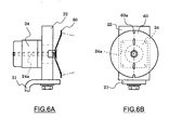
- the rotary member may be defined by a disc-shaped member 60.
- the guide portions provided in the rotary member for guiding the selvage yarns ST, ST may alternatively be defined by cutouts provided in the rotary member (e.g. cutouts 60a in Figs. 6A and 6B) in place of the aforementioned guide holes.
- the supporting plate 43 which supports the bobbin holder 41 and the guide segment 46 and is driven directly by the driving motor 52, and the supporting plate 44 supporting the bobbin holder 42 and the guide segment 47 are linked with each other in series. This means that in response to a rotation of the output shaft 52a, the bobbin holders 41, 42 rotate simultaneously, thus allowing the guide segments 46, 47 to revolve simultaneously.
- the selvage feeding mechanism 30 allows for other alternatives.
- the selvage yarns ST, ST may be fed towards the selvage shedding mechanism 20 in the following manner.
- a pair of selvage bobbins may be disposed on a rotary-driven disc-shaped or arm-like rotary member (rotating unit) so that when the rotary member is rotated, the selvage yarns ST, ST are fed from the corresponding selvage bobbins via a pair of guide holes that revolve about the rotational axis of the rotary member.
- a single rotary member functions both as the guide unit and the rotating unit according to the present invention.
- the guide unit and the rotating unit of the selvage feeding mechanism according to the present invention may be defined by separate components or a single component.
- the pair of selvage bobbins 41a, 42a does not necessarily have to rotate or revolve simultaneously in response to the rotation of the rotating unit as in the first embodiment.
- at least one of the selvage bobbins may be disposed in a non-rotatable fashion.
- the supporting plate 44 in the selvage feeding mechanism 30 may be fixedly supported by, for example, the corresponding side frame 1 of the loom without being linked with the supporting plate 43, such that only the supporting plate 43 is rotated in response to the rotation of the output shaft 52a of the driving motor 52.
- the guide holes 46a, 47a of the guide segments 46, 47 may be positionally adjusted, such that the first selvage yarn ST extending from the selvage bobbin 41a to the selvage shedding mechanism 20 via the guide hole 46a revolves around the second selvage yarn ST from the selvage bobbin 42a in response to the rotation of the supporting plate 43.
- the pair of selvage bobbins 41a, 42a may both be supported in a non-rotatable fashion.
- the guide unit (guide portions) that guides the selvage yarns ST, ST between the selvage bobbins 41a, 42a and the selvage shedding mechanism 20 may be driven in a rotating (revolving) fashion.
Landscapes
- Engineering & Computer Science (AREA)
- Textile Engineering (AREA)
- Looms (AREA)
Abstract
Description
- The present invention relates to selvage devices in looms, and particularly, to a selvage device in a loom, which rotates a rotary member having a pair of guides that guides selvage yarns so as to allow the selvage yarns to perform a shedding motion.
- PCT Japanese Translation Patent Publication No. 11-501999 (hereinafter referred to as "
JP11-501999T Japanese Unexamined Patent Application Publication No. 2000- 170052 JP2000-170052A JP11-501999T - In the selvage device according to the above-referenced examples, the selvage yarns twist around each other at the upstream side of the arms (i.e. closer towards the let-off side of the selvage yarns) in response to the rotation of the arms. The number of twists between the selvage yarns increases in proportion to the number of rotations of the arms. This means that if the yarns are not untwisted, the number of twists becomes too large to an extent that the yarns may break. For this reason, when performing a weaving operation, it is necessary to continuously untwist these selvage yarns.
- In order to achieve this untwisting of the selvage yarns, a selvage operation in the selvage device according to
JP11-501999T - Nonetheless, the selvage yarns still twist around each other at the upstream side in response to the predetermined number of rotations of the arms. If the selvage yarns are not strong, such twisting may increase the possibility of yarn breakages. For this reason, the types of selvage yarns that can be used in the selvage device of
JP11-501999T - On the other hand, as an alternative to the above-referenced type that rotates the pair of arms in the reverse direction,
JP2000-170052A - The selvage device of this type mainly includes a selvage shedding mechanism that moves the selvage yarns in a shedding motion, and the above-referenced untwisting mechanism that is disposed upstream of the selvage shedding mechanism. Specifically, the selvage shedding mechanism includes a guide unit having a pair of guide holes at opposite ends thereof for guiding selvage yarns. In detail, the guide unit is rotated with a driving shaft, which is driven by a main motor of the loom, so as to allow the selvage yarns to perform a shedding motion. On the other hand, the untwisting mechanism includes a rotary plate having a pair of yarn feeders disposed thereon. The rotary plate is provided with guide holes for guiding the selvage yarns fed out from the yarn feeders. Accordingly, even if the selvage yarns twist around each other at the upstream side of the guide unit due to the rotation of the guide unit, the untwisting mechanism allows the twisted selvage yarns to revolve in response to the rotating guide unit so that these yarns are untwisted from each other.
- In this selvage device, the selvage shedding mechanism applies the main motor of the loom as a driving source, such that the guide unit is rotated continuously at a substantially constant speed. For this reason, the dimension of the shed between the selvage yarns changes continuously at high speed, which means that a period in which the shed is at or close to its maximum dimension is extremely short. Therefore, in the selvage device according to
JP2000-170052A - Accordingly, it is an object of the present invention to provide a selvage device in a loom that is provided with a function for untwisting selvage yarns, which are twisted around each other at the upstream side of a selvage shedding mechanism in response to a rotation of a rotary member, without having to increase the size of the selvage shedding mechanism, thereby effectively preventing, for example, breakage of selvage yarns.
- According to an aspect of the present invention, a selvage device for a loom is provided. The selvage device has a rotary member provided with guides for guiding selvage yarns, and rotates the rotary member to move the selvage yarns in a shedding motion. The selvage device is characterized by including a selvage shedding mechanism having the rotary member and a designated driving motor that rotates the rotary member unidirectionally in an intermittent fashion; and a selvage feeding mechanism disposed upstream of the selvage shedding mechanism in a traveling direction of the selvage yarns. The selvage feeding mechanism includes a guide unit having a pair of guide portions for guiding the selvage yarns respectively fed from a pair of yarn feeders; and a rotating unit supporting the guide unit and rotated continuously in the same rotational direction as the rotary member. The guide portions revolve in response to the rotation of the rotating unit, such that sections of the selvage yarns extending from the yarn feeders to the corresponding guide portions revolve without intercrossing each other.
- The meaning of the phrase "sections of the selvage yarns extending from the yarn feeders to the corresponding guide portions revolve without intercrossing each other" will be described here in detail. Specifically, when these sections of the selvage yarns revolve in response to the revolving motion of the guide portions of the guide unit, these sections of the selvage yarns are prevented from coming into contact with each other at any position during each rotation of the rotating unit. Or in other words, these sections of the selvage yarns are constantly at different positions during each rotation of the rotating unit. Furthermore, the phrase "rotates the rotary member ... in an intermittent fashion" includes regularly alternating between different operation modes for predetermined periods, such as alternating stopping and rotating processes and alternating between low-speed rotation and high-speed rotation modes. Furthermore, the term "revolve" includes an orbital movement about a certain axis line or along a circular orbit around a component.
- Furthermore, in the selvage device according to the aspect of the present invention, the selvage feeding mechanism may be provided with a designated driving motor that rotates the rotating unit.
- According to the present invention, the selvage shedding mechanism is provided with a designated driving motor, which is independent of a main motor of the loom. The driving motor intermittently rotates the rotary member, such as an arm, which guides a pair of selvage yarns. Consequently, for a desired time within a weft insertion period, the rotary member can be kept in position (rotational phase) so that the shed between the selvage yarns is maintained at or close to its maximum dimension. Therefore, a required shed dimension for a weft insertion period is sufficiently attained without having to increase the distance between the guides for guiding the selvage yarns and also without having to increase the size of the rotary member.
- Moreover, in the selvage device according to the present invention in which the rotary member of the selvage shedding mechanism is driven intermittently with a designated driving motor, an untwisting mechanism (i.e. the selvage feeding mechanism) is disposed upstream of the selvage shedding mechanism in the traveling direction of the selvage yarns. Such an untwisting mechanism untwists the selvage yarns from each other by revolving the guide unit instead of rotating the rotary member in the reverse direction every time the rotary member is rotated for a predetermined number of turns as in the related art. This prevents the selvage yarns from twisting around each other multiple times at the upstream side of the selvage shedding mechanism. Accordingly, this prevents uneven selvage edges of woven cloth caused by the reverse rotation of the rotary member, and also prevents, for example, breakage of selvage yarns, which may be caused by the twisting of the selvage yarns.
- Furthermore, by providing the selvage feeding mechanism with a designated driving motor for driving the rotating unit, a drive transmission mechanism between a main motor of the loom and the selvage feeding mechanism can be omitted. This contributes to a simplified overall structure of the loom. Furthermore, the unitization of the selvage device simplifies the mounting process of the selvage device to a loom, and also contributes to an easier position adjustment of the selvage device with respect to the loom.
-
- Fig. 1 is a side view of a selvage device according to a first embodiment of the present invention;
- Fig. 2 is a partial plan view of the selvage device according to the first embodiment;
- Figs. 3A and 3B are a side view and a front view, respectively, illustrating a relevant section of the selvage device according to the first embodiment;
- Fig. 4 is a side view illustrating a relevant section of the selvage device according to the first embodiment;
- Figs. 5A and 5B are a plan view and a front view, respectively, illustrating a relevant section of the selvage device according to the first embodiment; and
- Figs. 6A and 6B are a side view and a front view, respectively, illustrating a relevant section of the selvage device according to an alternative embodiment of the present invention.
- Preferred embodiments of the present invention will now be described with reference to the drawings.
- Figs. 1 to 4 illustrate a
selvage device 10 according to a first embodiment of the present invention. Theselvedge device 10 mainly includes a pair ofselvage shedding mechanisms 20 and a pair ofselvage feeding mechanisms 30. Referring to Figs. 1 and 2, abeam 3 extending between opposite side frames 1, 1 of a loom supports theselvage shedding mechanisms 20 respectively with, for example, a pair of supporting blocks 5. Eachselvage shedding mechanism 20 is positioned outside a warp array T formed of a plurality of warp yarns. On the other hand, theselvage feeding mechanisms 30 are supported respectively by the opposite side frames 1, 1 with, for example, a pair of supporting blocks 7. - Although the first embodiment is generally directed to both
selvage shedding mechanisms 20, the description below will refer to only one of theselvage shedding mechanisms 20 in order to provide an easier understanding of the configuration, unless otherwise noted. Referring to Figs. 1, 2, 3A, and 3B, theselvage shedding mechanism 20 according to the first embodiment mainly includes a designated drivingmotor 24 functioning as a driving source, and anarm 26 attached to anoutput shaft 24a of the drivingmotor 24 and functioning as a rotary member according to the present invention. The drivingmotor 24 is attached to abracket 22, such that theselvage shedding mechanism 20 is supported by the corresponding supporting block 5 on thebeam 3 via astay 21 and thebracket 22. The supporting block 5 is attached to thebeam 3 in an adjustable fashion in the longitudinal direction of thebeam 3. Consequently, by adjusting the position of the supporting block 5, theselvage shedding mechanism 20 can be positionally adjusted in the width direction of the loom (that is, in the horizontal direction in Fig. 2). - The
output shaft 24a of the drivingmotor 24 is hollow, such that two selvage yarns ST, ST from the correspondingselvage feeding mechanism 30 extend through the interior of theoutput shaft 24a. Moreover, an end of theoutput shaft 24a proximate to a cloth fell CF (i.e. the downstream side of theoutput shaft 24a in the traveling direction of the selvage yarns ST, ST) has thearm 26 attached thereto in a relatively non-rotatable fashion. Opposite ends of thearm 26 are respectively provided withselvage guides output shaft 24a are guided respectively through the guide holes of the selvage guides 26a, 26a so as to extend toward the cloth fell CF of cloth W via areed 9. In Figs. 3A and 3B, the selvage guides 26a, 26a are separate components from thearm 26 and are mounted to thearm 26 to function as guides provided in the rotary member according to the present invention. Alternatively, these selvage guides 26a, 26a may be omitted. In that case, the guides in the rotary member may be defined by guide holes provided directly at the opposite ends of thearm 26, such that the selvage yarns ST, ST extend respectively through these guide holes. Furthermore, thearm 26 functioning as the rotary member does not necessarily have to be formed of a single-piece material. For example, the rotary member may alternatively be defined by a pair of arms attached to theoutput shaft 24a. - The driving
motor 24 for theselvage shedding mechanism 20 according to the present invention rotates intermittently at a predetermined timing in each weaving cycle. For example, the drivingmotor 24 stops at a rotational phase at which a shed formed between the two selvage yarns ST, ST reaches its maximum dimension; rotates by 180° at a predetermined timing within a weaving cycle (for example, a timing set in correspondence to an end timing of weft insertion); and then stops again. Consequently, the shed formed between the selvage yarns ST, ST is temporarily closed between a point where a weft yarn is inserted and a point of the rotation process. The shed is then formed again so that the next weft yarn can be inserted. When the shed reaches its maximum dimension, the shed is maintained in that state so as to prepare for the insertion of that weft yarn. Accordingly, the drivingmotor 24 for theselvage shedding mechanism 20 is driven intermittently in the following driving pattern: the drivingmotor 24 is rotated by 180° within a period extending from the predetermined timing to a point at which the subsequent weft yarn passes through the shed formed between the selvage yarns ST, ST, and is stopped until the next predetermined timing. However, the driving operation of the drivingmotor 24 does not necessarily have to be implemented by alternating the rotating and stopping processes as described above. For example, the drivingmotor 24 may be driven by alternating between low-speed rotation and high-speed rotation modes. In other words, the drivingmotor 24 may be switched to a low-speed rotation mode at the rotational phase at which the shed reaches its maximum dimension. In this low-speed rotation mode, the shed is maintained at a required dimension or more over a predetermined period of time. Upon completion of weft insertion, the drivingmotor 24 may be switched back to the high-speed rotation mode. - Furthermore, the
selvage shedding mechanism 20 is provided with adetector segment 28 for detecting breakage of the selvage yarns ST, ST. Specifically, thedetector segment 28 is disposed on the end of theoutput shaft 24a proximate to the cloth fell CF and is positioned near a side of thearm 26 most distant from the cloth fell CF. Thedetector segment 28 is formed of a thin-plate-like material having elasticity and has a pair of cutouts 28a at opposite ends thereof for hooking the selvage yarns ST, ST, respectively. As indicated by a solid line in Fig. 3A, thedetector segment 28 is normally in a bent state due to the tension of the selvage yarns ST, ST. On the other hand, when the selvage yarns ST, ST break, thedetector segment 28 becomes released from the tension of the selvage yarns ST, ST, whereby thedetector segment 28 is displaced to a position indicated by a dotted line due to its own elasticity. By detecting the displacement of thedetector segment 28 with, for example, a sensor, the breakage of the selvage yarns ST, ST can be detected. - Furthermore, the
selvage shedding mechanism 20 is also provided with aguide 29 for regulating the lateral positioning of the selvage yarns ST, ST extending from the selvage guides 26a, 26a of thearm 26. Referring to Fig. 3B, theguide 29 is substantially U-shaped and extends in the vertical direction. Moreover, theguide 29 is supported by thebracket 22 with astay 29a disposed therebetween. Theguide 29 regulates the selvage yarns ST, ST positionally in the lateral direction when thearm 26 is rotating. For example, even when thearm 26 is in a horizontally-extending state or close to that state, theguide 29 allows each selvage yarn ST to have a small angle with respect to the shifting direction of thereed 9 so as to reduce friction between the selvage yarn ST and the dents in thereed 9. - Similar to the above, although the first embodiment is generally directed to both
selvage feeding mechanisms 30, the description below will refer to only one of theselvage feeding mechanisms 30 in order to provide an easier understanding of the configuration, unless otherwise noted. Referring to Figs. 1, 2, 4, 5A and 5B, theselvage feeding mechanism 30 mainly includes ayarn feeder element 40 and adriver element 50. Figs. 5A and 5B show a state where theyarn feeder element 40 is rotated from the state shown in Figs. 1 and 4, such that arotary guide member 45, which will be described below, is set in a substantially horizontal state. - Similar to the
selvage shedding mechanism 20, theselvage feeding mechanism 30 according to the first embodiment is provided with a designated drivingmotor 52 functioning as a driving source. Specifically, the drivingmotor 52 is included in thedriver element 50. Thedriver element 50 is supported by thecorresponding side frame 1 by being linked with abracket 53, abase plate 51, and the corresponding supporting block 7 attached to theside frame 1. - In the
driver element 50, the drivingmotor 52 is supported in a manner such that anoutput shaft 52a thereof extends through afirst stay portion 53a of thebracket 53. Furthermore, thebracket 53 has asecond stay portion 53b, which supports ashaft coupling 55 with, for example, a bearing, not shown. One end of theshaft coupling 55 is attached to theoutput shaft 52a of the drivingmotor 52 in a relatively non-rotatable fashion. The other end of theshaft coupling 55 is fixedly attached to theyarn feeder element 40. Accordingly, theyarn feeder element 40 is rotatably supported by thebracket 53 via theshaft coupling 55, and is linked with theoutput shaft 52a of the drivingmotor 52 via theshaft coupling 55. - The driving
motor 52 is driven in a manner such that theoutput shaft 52a makes one continuous rotation every time thearm 26 of the correspondingselvage shedding mechanism 20 makes one rotation, or in other words, theoutput shaft 52a makes one continuous rotation for every two weaving cycles of the loom. - Furthermore, the
yarn feeder element 40 includes a pair ofbobbin holders selvage bobbins plates bobbin holders rotary guide member 45 provided with a pair of selvage guides 45a, 45b having guide holes through which the selvage yarns ST, ST extend, respectively. - The supporting
plates bracings 48. Consequently, the twoselvage bobbins output shaft 52a of the drivingmotor 52. The supportingplate 43 is attached to theshaft coupling 55 of thedriver element 50 and is driven directly by the drivingmotor 52. - The
rotary guide member 45 is formed of a narrow plate that is bent into a shape as shown in Fig. 5A, and is attached to the supportingplate 44 in a manner such that therotary guide member 45 is disposed across a diagonal line of the supportingplate 44. The selvage guides 45a, 45b are attached to an end portion of therotary guide member 45 proximate to theselvage shedding mechanism 20. - For example, the
bobbin holders Japanese Unexamined Patent Application Publication No. 7-48749 bobbin holders selvage bobbins selvage bobbins - Furthermore, the
bobbin holders guide segments selvage bobbins guide segments plates bobbin holders - The
guide segments guide holes respective bobbin holders plates 43, 44 (the rotational-axis line = the center of axle of theoutput shaft 52a of the driving motor 52). The selvage yarns ST, ST from therespective selvage bobbins guide holes guide segments rotary guide member 45. The selvage guides 45a, 45b then guide the selvage yarns ST, ST towards theselvage shedding mechanism 20. - According to the
selvage feeding mechanism 30, the supportingplates bracings 48 are integrally rotated in response to the rotation of theoutput shaft 52a of the drivingmotor 52. Therefore, the supportingplates - When the supporting
plates bobbin holders plates plates guide segments bobbin holders plates guide segments guide holes guide segments - In the first embodiment, the
rotary guide member 45 having the selvage guides 45a, 45b is attached to the supportingplate 44, which implies that the selvage guides 45a, 45b also revolve about the rotational axis of the supportingplates plates rotary guide member 45 may also function as the guide unit according to the present invention, and the selvage guides 45a, 45b may also function as the pair of guide portions according to the present invention. In this case, however, the guide holes in therotary guide member 45 do not necessarily have to function as the pair of guide portions according to the present invention. For example, in place of the selvage guides 45a, 45b, therotary guide member 45 may be provided with only a single guide hole through which the two selvage yarns ST, ST can both extend. As another alternative, therotary guide member 45 may be omitted. In that case, for example, the selvage yarns ST, ST may be guided towards theselvage shedding mechanism 20 directly from theguide segments bobbin holders - In the
selvage device 10 according to the first embodiment, when thearm 26 of theselvage shedding mechanism 20 is rotated intermittently in one direction, the two selvage yarns ST, ST connected to the cloth fell CF revolve about the center of rotation of thearm 26 to form a shed therebetween for each weaving cycle of the loom, whereby a selvage operation is successfully performed on the cloth W. Moreover, since the rotational direction of thearm 26 is fixed to one direction, the selvage operation is performed properly without forming uneven selvage edges. - Although the selvage yarns ST, ST twist around each other at the upstream side of the
arm 26 in response to the unidirectional rotation of thearm 26, the selvage yarns ST, ST are constantly untwisted from each other due to the revolving motions of theguide holes selvage feeding mechanism 30 in the same direction as the rotational direction of thearm 26. In other words, the first selvage yarn ST, which extends from theselvage bobbin 41a to theselvage shedding mechanism 20 via theguide hole 46a and theselvage guide 45a, and the second selvage yarn ST, which extends from theselvage bobbin 42a to theselvage shedding mechanism 20 via theguide hole 47a and theselvage guide 45b, revolve about the rotational axis of the supportingplates plates 43, 44 (bobbin holders 41, 42). This is due to the revolving motions of theguide hole 46a and theselvage guide 45a and the revolving motions of theguide hole 47a and theselvage guide 45b about the rotational axis of the supportingplates arm 26, the selvage yarns ST, ST are untwisted from each other downstream in response to the rotation of thearm 26. Accordingly, this prevents breakage of the selvage yarns ST, ST, which may be caused when the selvage yarns ST, ST are twisted around each other a large number of times. - Unlike the first embodiment in which each
selvage feeding mechanism 30 has the designated drivingmotor 52 as a driving source, eachselvage feeding mechanism 30 may be driven alternatively by a main motor of the loom. Similar to the description of the first embodiment, the description below will refer to only one of theselvage shedding mechanisms 20 and one of theselvage feeding mechanisms 30 in order to provide an easier understanding of the configuration, unless otherwise noted. - In the
selvage shedding mechanism 20 according the first embodiment, thearm 26 having the selvage guides 26a, 26a at opposite ends thereof for guiding the selvage yarns ST, ST is provided as a rotary member. Alternatively, as shown in Figs. 6A and 6B, for example, the rotary member may be defined by a disc-shapedmember 60. Furthermore, the guide portions provided in the rotary member for guiding the selvage yarns ST, ST may alternatively be defined by cutouts provided in the rotary member (e.g. cutouts 60a in Figs. 6A and 6B) in place of the aforementioned guide holes. - In the first embodiment, the supporting
plate 43, which supports thebobbin holder 41 and theguide segment 46 and is driven directly by the drivingmotor 52, and the supportingplate 44 supporting thebobbin holder 42 and theguide segment 47 are linked with each other in series. This means that in response to a rotation of theoutput shaft 52a, thebobbin holders guide segments selvage feeding mechanism 30 according to the present invention allows for other alternatives. - For example, similar to the selvage device disclosed in
Japanese Unexamined Patent Application Publication No. 2000-170052 selvage shedding mechanism 20 in the following manner. In detail, a pair of selvage bobbins may be disposed on a rotary-driven disc-shaped or arm-like rotary member (rotating unit) so that when the rotary member is rotated, the selvage yarns ST, ST are fed from the corresponding selvage bobbins via a pair of guide holes that revolve about the rotational axis of the rotary member. In this case, a single rotary member functions both as the guide unit and the rotating unit according to the present invention. In other words, the guide unit and the rotating unit of the selvage feeding mechanism according to the present invention may be defined by separate components or a single component. - In the
selvage feeding mechanism 30 according to the present invention, the pair ofselvage bobbins - For example, in the
selvage device 10 according to the first embodiment, the supportingplate 44 in theselvage feeding mechanism 30 may be fixedly supported by, for example, thecorresponding side frame 1 of the loom without being linked with the supportingplate 43, such that only the supportingplate 43 is rotated in response to the rotation of theoutput shaft 52a of the drivingmotor 52. In that case, theguide holes guide segments selvage bobbin 41a to theselvage shedding mechanism 20 via theguide hole 46a revolves around the second selvage yarn ST from theselvage bobbin 42a in response to the rotation of the supportingplate 43. - Furthermore, like a selvage shedding device disclosed in
Japanese Unexamined Patent Application Publication No. 60-34642 selvage bobbins bobbin holders 41, 42) may both be supported in a non-rotatable fashion. In that case, only the guide unit (guide portions) that guides the selvage yarns ST, ST between theselvage bobbins selvage shedding mechanism 20 may be driven in a rotating (revolving) fashion. - The technical scope of the present invention is not limited to the above embodiments, and modifications are permissible within the scope and spirit of the present invention.
Claims (2)
- A selvage device (10) in a loom having a rotary member (26, 60) provided with guides (26a, 60a) for guiding selvage yarns (ST), the rotary member (26, 60) being rotated so as to move the selvage yarns (ST) in a shedding motion, the selvage device (10) characterized by comprising:a selvage shedding mechanism (20) including the rotary member (26, 60) and a designated driving motor (24) that rotates the rotary member (26, 60) unidirectionally in an intermittent fashion; anda selvage feeding mechanism (30) disposed upstream of the selvage shedding mechanism (20) in a traveling direction of the selvage yarns (ST),wherein the selvage feeding mechanism (30) includes:a guide unit having a pair of guide portions (46a, 47a, 45a, 45b) for guiding the selvage yarns (ST) respectively fed from a pair of yarn feeders; anda rotating unit supporting the guide unit and rotated in the same rotational direction as the rotary member (26, 60),wherein the guide portions (46a, 47a, 45a, 45b) revolve in response to the rotation of the rotating unit, such that sections of the selvage yarns (ST) extending from the yarn feeders to the corresponding guide portions (46a, 47a, 45a, 45b) revolve without intercrossing each other.
- The selvage device (10) according to Claim 1,
wherein the selvage feeding mechanism (30) is provided with a designated driving motor (52) that rotates the rotating unit.
Applications Claiming Priority (2)
| Application Number | Priority Date | Filing Date | Title |
|---|---|---|---|
| JP2005152269 | 2005-05-25 | ||
| JP2005303862A JP2007002385A (en) | 2005-05-25 | 2005-10-19 | Loom ear assembly equipment |
Publications (2)
| Publication Number | Publication Date |
|---|---|
| EP1726696A2 true EP1726696A2 (en) | 2006-11-29 |
| EP1726696A3 EP1726696A3 (en) | 2007-03-07 |
Family
ID=36954643
Family Applications (1)
| Application Number | Title | Priority Date | Filing Date |
|---|---|---|---|
| EP06006887A Withdrawn EP1726696A3 (en) | 2005-05-25 | 2006-03-31 | Selvage device in loom |
Country Status (2)
| Country | Link |
|---|---|
| EP (1) | EP1726696A3 (en) |
| JP (1) | JP2007002385A (en) |
Family Cites Families (6)
| Publication number | Priority date | Publication date | Assignee | Title |
|---|---|---|---|---|
| JP3994559B2 (en) * | 1998-12-10 | 2007-10-24 | 株式会社豊田自動織機 | Ear forming device in loom |
| US6546966B2 (en) * | 2001-03-27 | 2003-04-15 | Sulzer Textil Ag | Apparatus for making available a leno thread for a weaving machine |
| JP2003221747A (en) * | 2002-01-23 | 2003-08-08 | Tsudakoma Corp | Control method for electric lug assembly device of fluid jet loom |
| JP3997926B2 (en) * | 2003-02-19 | 2007-10-24 | 株式会社豊田自動織機 | Loom equipped with muzzle ear forming device |
| DE10342814A1 (en) * | 2003-09-17 | 2005-04-21 | Heinz Peter Loehr | De-twisting device on feed side of twisting disk for producing twist selvedge with unidirectional twist includes driven rotating yarn guide for one yarn |
| ITVI20040196A1 (en) * | 2004-08-05 | 2004-11-05 | Smit Spa | DEVICE FOR THE FORMATION OF THE BINDING OF THE EDGES OF A FABRIC PRODUCED WITH TEXTILE MACHINES WITHOUT SHUTTLE |
-
2005
- 2005-10-19 JP JP2005303862A patent/JP2007002385A/en active Pending
-
2006
- 2006-03-31 EP EP06006887A patent/EP1726696A3/en not_active Withdrawn
Also Published As
| Publication number | Publication date |
|---|---|
| EP1726696A3 (en) | 2007-03-07 |
| JP2007002385A (en) | 2007-01-11 |
Similar Documents
| Publication | Publication Date | Title |
|---|---|---|
| US5518039A (en) | Leno selvage device having a leno rotor forming the rotor of an electric motor | |
| JP3278811B2 (en) | Apparatus for forming Leno ears, especially for shuttleless looms | |
| US9359698B2 (en) | Shedding apparatus for waste selvage in a loom | |
| US5524678A (en) | Leno selvage device for a loom with a leno rotor driven by its own motor | |
| US5988228A (en) | Leno selvage former for a weaving loom | |
| JP2000212861A (en) | Compensation of elongation or change of tension of warp yarn and loom for executing the same | |
| JP3425432B2 (en) | Terry loom | |
| JP3416661B2 (en) | Terry loom | |
| JPH0369627A (en) | Twist selvadge forming device in weaving machine | |
| US6098670A (en) | Apparatus for tensioning warp threads for a weaving machine and a weaving machine with an apparatus of this kind | |
| JP2006045762A5 (en) | ||
| JPS5830429B2 (en) | Reno Ityou Kaiten Karamiori Souchi | |
| KR830002718Y1 (en) | Weaving machines in looms | |
| EP1179623B1 (en) | Device for forming the leno heald weave in weaving looms | |
| CN219079754U (en) | Adjustable warping machine | |
| JPH07118982A (en) | Selvedge yarn feeding apparatus for selvedge-forming apparatus of loom | |
| JP2003313755A (en) | Ear warp break detector | |
| JP2007002385A (en) | Loom ear assembly equipment | |
| JP2007002386A (en) | Loom ear assembly equipment | |
| KR830002354B1 (en) | Tension control feed device | |
| JP2591067B2 (en) | Ear forming device in shuttleless loom | |
| JPH07138839A (en) | Weft tension controller for loom | |
| JPS6039778B2 (en) | Circular loom warp alignment device | |
| JP2595726B2 (en) | Tow ear forming device in loom | |
| JPH07173744A (en) | Production of woven fabric of foil and shuttle therefor |
Legal Events
| Date | Code | Title | Description |
|---|---|---|---|
| PUAI | Public reference made under article 153(3) epc to a published international application that has entered the european phase |
Free format text: ORIGINAL CODE: 0009012 |
|
| AK | Designated contracting states |
Kind code of ref document: A2 Designated state(s): AT BE BG CH CY CZ DE DK EE ES FI FR GB GR HU IE IS IT LI LT LU LV MC NL PL PT RO SE SI SK TR |
|
| AX | Request for extension of the european patent |
Extension state: AL BA HR MK YU |
|
| PUAL | Search report despatched |
Free format text: ORIGINAL CODE: 0009013 |
|
| AK | Designated contracting states |
Kind code of ref document: A3 Designated state(s): AT BE BG CH CY CZ DE DK EE ES FI FR GB GR HU IE IS IT LI LT LU LV MC NL PL PT RO SE SI SK TR |
|
| AX | Request for extension of the european patent |
Extension state: AL BA HR MK YU |
|
| AKX | Designation fees paid | ||
| STAA | Information on the status of an ep patent application or granted ep patent |
Free format text: STATUS: THE APPLICATION IS DEEMED TO BE WITHDRAWN |
|
| 18D | Application deemed to be withdrawn |
Effective date: 20070908 |
|
| REG | Reference to a national code |
Ref country code: DE Ref legal event code: 8566 |