EP1725356B1 - Cold nozzle for laser processing - Google Patents
Cold nozzle for laser processing Download PDFInfo
- Publication number
- EP1725356B1 EP1725356B1 EP04812436A EP04812436A EP1725356B1 EP 1725356 B1 EP1725356 B1 EP 1725356B1 EP 04812436 A EP04812436 A EP 04812436A EP 04812436 A EP04812436 A EP 04812436A EP 1725356 B1 EP1725356 B1 EP 1725356B1
- Authority
- EP
- European Patent Office
- Prior art keywords
- slug
- nozzle
- mandrel
- shaped mandrel
- forcing
- Prior art date
- Legal status (The legal status is an assumption and is not a legal conclusion. Google has not performed a legal analysis and makes no representation as to the accuracy of the status listed.)
- Expired - Lifetime
Links
Images


Classifications
-
- B—PERFORMING OPERATIONS; TRANSPORTING
- B23—MACHINE TOOLS; METAL-WORKING NOT OTHERWISE PROVIDED FOR
- B23K—SOLDERING OR UNSOLDERING; WELDING; CLADDING OR PLATING BY SOLDERING OR WELDING; CUTTING BY APPLYING HEAT LOCALLY, e.g. FLAME CUTTING; WORKING BY LASER BEAM
- B23K26/00—Working by laser beam, e.g. welding, cutting or boring
- B23K26/14—Working by laser beam, e.g. welding, cutting or boring using a fluid stream, e.g. a jet of gas, in conjunction with the laser beam; Nozzles therefor
- B23K26/1462—Nozzles; Features related to nozzles
- B23K26/1464—Supply to, or discharge from, nozzles of media, e.g. gas, powder, wire
-
- B—PERFORMING OPERATIONS; TRANSPORTING
- B21—MECHANICAL METAL-WORKING WITHOUT ESSENTIALLY REMOVING MATERIAL; PUNCHING METAL
- B21C—MANUFACTURE OF METAL SHEETS, WIRE, RODS, TUBES, PROFILES OR LIKE SEMI-MANUFACTURED PRODUCTS OTHERWISE THAN BY ROLLING; AUXILIARY OPERATIONS USED IN CONNECTION WITH METAL-WORKING WITHOUT ESSENTIALLY REMOVING MATERIAL
- B21C23/00—Extruding metal; Impact extrusion
- B21C23/02—Making uncoated products
- B21C23/20—Making uncoated products by backward extrusion
-
- B—PERFORMING OPERATIONS; TRANSPORTING
- B21—MECHANICAL METAL-WORKING WITHOUT ESSENTIALLY REMOVING MATERIAL; PUNCHING METAL
- B21K—MAKING FORGED OR PRESSED METAL PRODUCTS, e.g. HORSE-SHOES, RIVETS, BOLTS OR WHEELS
- B21K21/00—Making hollow articles not covered by a single preceding sub-group
- B21K21/08—Shaping hollow articles with different cross-section in longitudinal direction, e.g. nozzles, spark-plugs
-
- Y—GENERAL TAGGING OF NEW TECHNOLOGICAL DEVELOPMENTS; GENERAL TAGGING OF CROSS-SECTIONAL TECHNOLOGIES SPANNING OVER SEVERAL SECTIONS OF THE IPC; TECHNICAL SUBJECTS COVERED BY FORMER USPC CROSS-REFERENCE ART COLLECTIONS [XRACs] AND DIGESTS
- Y10—TECHNICAL SUBJECTS COVERED BY FORMER USPC
- Y10S—TECHNICAL SUBJECTS COVERED BY FORMER USPC CROSS-REFERENCE ART COLLECTIONS [XRACs] AND DIGESTS
- Y10S372/00—Coherent light generators
- Y10S372/701—Nozzle
-
- Y—GENERAL TAGGING OF NEW TECHNOLOGICAL DEVELOPMENTS; GENERAL TAGGING OF CROSS-SECTIONAL TECHNOLOGIES SPANNING OVER SEVERAL SECTIONS OF THE IPC; TECHNICAL SUBJECTS COVERED BY FORMER USPC CROSS-REFERENCE ART COLLECTIONS [XRACs] AND DIGESTS
- Y10—TECHNICAL SUBJECTS COVERED BY FORMER USPC
- Y10T—TECHNICAL SUBJECTS COVERED BY FORMER US CLASSIFICATION
- Y10T29/00—Metal working
- Y10T29/49—Method of mechanical manufacture
- Y10T29/49345—Catalytic device making
-
- Y—GENERAL TAGGING OF NEW TECHNOLOGICAL DEVELOPMENTS; GENERAL TAGGING OF CROSS-SECTIONAL TECHNOLOGIES SPANNING OVER SEVERAL SECTIONS OF THE IPC; TECHNICAL SUBJECTS COVERED BY FORMER USPC CROSS-REFERENCE ART COLLECTIONS [XRACs] AND DIGESTS
- Y10—TECHNICAL SUBJECTS COVERED BY FORMER USPC
- Y10T—TECHNICAL SUBJECTS COVERED BY FORMER US CLASSIFICATION
- Y10T29/00—Metal working
- Y10T29/49—Method of mechanical manufacture
- Y10T29/49348—Burner, torch or metallurgical lance making
Definitions
- the present invention relates to lasers and more particularly a method for making a laser nozzle.
- a laser processing head typically includes a focusing optic to concentrate the laser beam and a nozzle, usually made of copper, having a conical inner surface tapering toward an outlet aperture for directing a stream of gas such as nitrogen, oxygen, or air coaxial with the focused laser beam.
- the inner surface of the nozzle serves as the boundary between the flowing gas at high pressures and the outside world.
- the roughness of the surface directly influences the turbulence of the flow. Additionally, any discontinuities from machining processes produce friction and turbulence.
- the laser usually consists of a YAG or CO2 lasing medium, at wavelengths between 1 and 11 microns. Normally the laser is aligned so as to travel through the nozzle without striking it. However, a misaligned laser beam will reflect or glance off of the inner surface of the nozzle. If the reflective properties of the surface are not sufficient the beam will be absorbed resulting in heat that can destroy or deform the contours of the nozzle. In addition, laser reflections off a work-piece during a laser operation may reflect back at the nozzle. This may cause damage to the nozzle if the inner and outer surfaces of the nozzle do not have adequate reflective properties.
- a new method of shaping the interior for cold forming a nozzle for a laser includes placing a slug of oxygen-free copper into a die. A mandrel is forced into this slug with a high compressive force causing the copper to cold flow around the mandrel. The inner surface of the slug is an exact replica in reverse of the mandrel and the outside of the slug assumes the shape of the outer retention die.
- a method of cold-forming a nozzle for a laser includes placing a slug of oxygen-free copper into a die.
- a shaped mandrel is forced into the slug causing the slug to be extruded around the mandrel.
- Compressive force is applied from the die onto the slug to define an outer dimension of the nozzle.
- Radial compressive force is applied onto an inner surface of the slug to define an inner dimension of the nozzle.
- forcing the shaped mandrel includes forcing a distal end of the shaped mandrel through the slug and defining an outlet aperture of the nozzle.
- Forcing the shaped mandrel further includes forcing a proximal end of the shaped mandrel into the slug and defining an inlet aperture of the nozzle.
- Applying the radial compressive force includes forcing the shaped mandrel through the slug whereby the shaped mandrel defines an engagement surface that tapers toward the distal end of the shaped mandrel.
- the engagement surface of the shaped mandrel urges the slug into an inner geometry of the die.
- Forcing the shaped mandrel includes locating the distal end of the shaped mandrel at a position beyond a portion of the slug identified to form the outlet aperture of the nozzle.
- FIG. 1A is a perspective view of a laser nozzle according to the present teachings
- FIG. 1B is a sectional view of the laser nozzle of FIG. 1 A;
- FIG. 2A is a perspective view of a laser nozzle according to additional features
- FIG. 2B is a sectional view of the laser nozzle of FIG. 2A ;
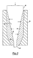
- FIG. 3 is a sectional view of a copper blank during swaging.
- FIG. 4 is a perspective view of a collection of laser nozzles according to present teachings.
- a laser nozzle according to the present teachings is shown and generally identified at reference numeral 10.
- the laser nozzle 10 generally includes an inner surface 12 and an outer surface 14.
- An inlet aperture 16 is arranged on a proximal end and an outlet aperture 18 is arranged on a distal end.
- a laser nozzle 30 having an alternate inner surface 32 is shown. Specifically the inner surface 32 provides an alternate outlet aperture 33 on its distal end.
- the shape of the nozzle head is merely exemplary and any laser nozzle geometry may be incorporated.
- the laser nozzle 10 is made of pure, oxygen-free, high conductivity copper using cold-forming. More specifically, the laser nozzle 10 is made by swaging a mandrel into a piece of high conductivity copper. First, a slug, tube or rod of copper 34 is placed inside a die 36. The desired geometry of the inner surface 38 is determined by forcing a mandrel 40 inside the slug or tube 34 thus causing the slug or tube 34 to cold flow around the mandrel 40.
- the mandrel 40 defines a tapered engagement surface 42 having a desired surface finish.
- the surface finish of the engagement surface 42 of the mandrel 40 including the predetermined inside geometry of the nozzle is transferred onto the inner surface 38 of the slug or tube 34.
- the mandrel 40 includes structure at a proximal end 48 and a distal end 46 for controlling the formation of the inlet aperture 16 and the outlet aperture 18 of the nozzle 10. More specifically, the mandrel 40 may extend beyond an area of the slug or tube 34 identified to form the inlet aperture 16 (proximal end 48) and the outlet aperture 18 (distal end 46) of the nozzle 10.
- the high pressure created by the mandrel 40 allows the unique features of the mandrel 40 to be precisely transferred to the pure oxygen-free, high conductivity copper tube 34.
- the profile of the mandrel 40 may be reproduced exactly in the profile of the inner surface 38.
- the cold-form process provides consistency of tolerances. As a result, repeatability is typically within 1-micron from part to part. In addition, ultra-smooth surface finish is achieved on critical interior surfaces of less than 0.007 microns RMS.
- the cold-form process allows a complete profile of the inner surface 38 including all diameters such as the outlet aperture 18 to be cold formed in a single pressing operation. Rough overall exterior shapes may also be formed by the cold-forming process. Final exterior contours and shapes may then be machined using existing precision diamond-tooling machine technology.
- the use of cold-formed pure, oxygen-free, high conductivity copper creates a several percent higher reflectivity to CO2 and YAG wavelengths from conventional machined copper nozzles. Such an increase in reflectivity has been shown to be 99.8% as compared to 97.5% with conventional machining.
- Conventional machined nozzles typically have an internal surface finish of around 1 micrometer.
- the cold-formed nozzle 10 according to the present invention has an internal surface finish of around 0.1 micrometer.
- the increased reflectivity reduces damage from misaligned laser beams or workpiece reflections striking the nozzle 10 during a cutting operation.
- the exterior 14 of the pure, oxygen-free, high conductivity copper nozzle body 10 can also be polished to a shiny smooth surface to reduce adhesion of cutting residues.
- other materials may be used. For example, silver-bearing copper, zirconium copper and others materials are contemplated.
- FIG. 4 a collection of laser nozzles 50 created by cold-forming technique described herein are shown.
- the wide range of controllable geometries of inner surfaces and outer surfaces are illustrated.
- the geometries of the laser nozzles 50 are merely exemplary, and any laser nozzle geometry is contemplated according to the teachings of the present invention.
Landscapes
- Engineering & Computer Science (AREA)
- Mechanical Engineering (AREA)
- Physics & Mathematics (AREA)
- Optics & Photonics (AREA)
- Plasma & Fusion (AREA)
- Laser Beam Processing (AREA)
- Nozzles (AREA)
- Metal Extraction Processes (AREA)
- Forging (AREA)
- Lasers (AREA)
Abstract
Description
- The present invention relates to lasers and more particularly a method for making a laser nozzle.
- Laser cutting has become an increasingly popular method of working a piece of material especially when precise tolerances are necessary. Currently, many laser processing heads incorporate features and devices that help ensure optimal and consistent processing results. A laser processing head typically includes a focusing optic to concentrate the laser beam and a nozzle, usually made of copper, having a conical inner surface tapering toward an outlet aperture for directing a stream of gas such as nitrogen, oxygen, or air coaxial with the focused laser beam.
- The inner surface of the nozzle serves as the boundary between the flowing gas at high pressures and the outside world. The roughness of the surface directly influences the turbulence of the flow. Additionally, any discontinuities from machining processes produce friction and turbulence. The laser usually consists of a YAG or CO2 lasing medium, at wavelengths between 1 and 11 microns. Normally the laser is aligned so as to travel through the nozzle without striking it. However, a misaligned laser beam will reflect or glance off of the inner surface of the nozzle. If the reflective properties of the surface are not sufficient the beam will be absorbed resulting in heat that can destroy or deform the contours of the nozzle. In addition, laser reflections off a work-piece during a laser operation may reflect back at the nozzle. This may cause damage to the nozzle if the inner and outer surfaces of the nozzle do not have adequate reflective properties.
- The current state-of-the-art uses nozzles that are machined on various high-speed lathes utilizing free machining copper alloys such as tellurium copper. The resulting nozzles while of high quality have a surface roughness inside or 15-20 micro inches RMS and can have burrs and chips left over from the material removal required. A new method of shaping the interior for cold forming a nozzle for a laser includes placing a slug of oxygen-free copper into a die. A mandrel is forced into this slug with a high compressive force causing the copper to cold flow around the mandrel. The inner surface of the slug is an exact replica in reverse of the mandrel and the outside of the slug assumes the shape of the outer retention die.
- Further areas of the applicability of the present invention will become apparent from the detailed description provided hereinafter. It should be understood that the detailed description and specific examples, while indicating the preferred embodiment of the invention, are intended for purposes of illustration only and are not intended to limit the scope of the invention as defined by the appended claims.
- A method of cold-forming a nozzle for a laser includes placing a slug of oxygen-free copper into a die. A shaped mandrel is forced into the slug causing the slug to be extruded around the mandrel. Compressive force is applied from the die onto the slug to define an outer dimension of the nozzle. Radial compressive force is applied onto an inner surface of the slug to define an inner dimension of the nozzle.
- According to other features, forcing the shaped mandrel includes forcing a distal end of the shaped mandrel through the slug and defining an outlet aperture of the nozzle. Forcing the shaped mandrel further includes forcing a proximal end of the shaped mandrel into the slug and defining an inlet aperture of the nozzle. Applying the radial compressive force includes forcing the shaped mandrel through the slug whereby the shaped mandrel defines an engagement surface that tapers toward the distal end of the shaped mandrel.
- According to yet other features, the engagement surface of the shaped mandrel urges the slug into an inner geometry of the die. Forcing the shaped mandrel includes locating the distal end of the shaped mandrel at a position beyond a portion of the slug identified to form the outlet aperture of the nozzle.
- The present invention will become more fully understood from the detailed description and the accompanying drawings, wherein;
-
FIG. 1A is a perspective view of a laser nozzle according to the present teachings; -
FIG. 1B is a sectional view of the laser nozzle ofFIG. 1 A; -
FIG. 2A is a perspective view of a laser nozzle according to additional features; -
FIG. 2B is a sectional view of the laser nozzle ofFIG. 2A ; -
FIG. 3 is a sectional view of a copper blank during swaging; and -
FIG. 4 is a perspective view of a collection of laser nozzles according to present teachings. - The following description of the preferred embodiment(s) is merely exemplary in nature and is in no way intended to limit the invention, its application or uses.
- With reference to the
FIGS. 1A and 1B , a laser nozzle according to the present teachings is shown and generally identified atreference numeral 10. Thelaser nozzle 10 generally includes aninner surface 12 and anouter surface 14. Aninlet aperture 16 is arranged on a proximal end and anoutlet aperture 18 is arranged on a distal end. As shown inFIGS. 2A and 2B , alaser nozzle 30 having an alternateinner surface 32 is shown. Specifically theinner surface 32 provides analternate outlet aperture 33 on its distal end. As will be described herein, the shape of the nozzle head is merely exemplary and any laser nozzle geometry may be incorporated. - With further reference now to
FIG. 3 , a method of making thelaser nozzle 10 will be described in greater detail. It will be appreciated that while the method will be explained with respect to thelaser nozzle 10, the same method may be employed to make thelaser nozzle 30 or any other laser nozzle. Thelaser nozzle 10 is made of pure, oxygen-free, high conductivity copper using cold-forming. More specifically, thelaser nozzle 10 is made by swaging a mandrel into a piece of high conductivity copper. First, a slug, tube or rod ofcopper 34 is placed inside a die 36. The desired geometry of theinner surface 38 is determined by forcing amandrel 40 inside the slug ortube 34 thus causing the slug ortube 34 to cold flow around themandrel 40. Themandrel 40 defines atapered engagement surface 42 having a desired surface finish. The surface finish of theengagement surface 42 of themandrel 40 including the predetermined inside geometry of the nozzle is transferred onto theinner surface 38 of the slug ortube 34. In addition, themandrel 40 includes structure at aproximal end 48 and adistal end 46 for controlling the formation of theinlet aperture 16 and theoutlet aperture 18 of thenozzle 10. More specifically, themandrel 40 may extend beyond an area of the slug ortube 34 identified to form the inlet aperture 16 (proximal end 48) and the outlet aperture 18 (distal end 46) of thenozzle 10. - The high pressure created by the
mandrel 40 allows the unique features of themandrel 40 to be precisely transferred to the pure oxygen-free, highconductivity copper tube 34. The profile of themandrel 40 may be reproduced exactly in the profile of theinner surface 38. The cold-form process provides consistency of tolerances. As a result, repeatability is typically within 1-micron from part to part. In addition, ultra-smooth surface finish is achieved on critical interior surfaces of less than 0.007 microns RMS. The cold-form process allows a complete profile of theinner surface 38 including all diameters such as theoutlet aperture 18 to be cold formed in a single pressing operation. Rough overall exterior shapes may also be formed by the cold-forming process. Final exterior contours and shapes may then be machined using existing precision diamond-tooling machine technology. - The use of cold-formed pure, oxygen-free, high conductivity copper creates a several percent higher reflectivity to CO2 and YAG wavelengths from conventional machined copper nozzles. Such an increase in reflectivity has been shown to be 99.8% as compared to 97.5% with conventional machining. Conventional machined nozzles typically have an internal surface finish of around 1 micrometer. The cold-formed
nozzle 10 according to the present invention has an internal surface finish of around 0.1 micrometer. The increased reflectivity reduces damage from misaligned laser beams or workpiece reflections striking thenozzle 10 during a cutting operation. Theexterior 14 of the pure, oxygen-free, high conductivitycopper nozzle body 10 can also be polished to a shiny smooth surface to reduce adhesion of cutting residues. In addition to pure, oxygen-free copper, other materials may be used. For example, silver-bearing copper, zirconium copper and others materials are contemplated. - With reference now to
FIG. 4 a collection oflaser nozzles 50 created by cold-forming technique described herein are shown. The wide range of controllable geometries of inner surfaces and outer surfaces are illustrated. Again, the geometries of thelaser nozzles 50 are merely exemplary, and any laser nozzle geometry is contemplated according to the teachings of the present invention. - While the invention has been described in the specification and illustrated in the drawings with reference to various embodiments, it will be understood by those skilled in the art that various changes may be made and equivalents may be substituted for elements thereof without departing from the scope of the invention as defined in the claims.
Claims (15)
- A method of cold-forming a nozzle (10) for a laser comprising:placing a slug (34) of oxygen-free copper (34) into a die (36),forcing a shaped mandrel (40) with an ultra-smooth surface into said slug (34) causing said slug (34) to be extruded around said mandrel (40), andforming the nozzle (10) with interior reflectivity of greater than 97.5% to CO2 and YAG laser wavelengths.
- The method of claim 1 wherein forcing said shaped mandrel (40) includes forcing a distal end of said shaped mandrel (40) through said slug (34) and defining an outlet aperture of the nozzle (10).
- The method of claim 2 wherein forcing said shaped mandrel (40) includes forcing a proximal end of said shaped mandrel (40) into said slug (34) and defining an inlet aperture of the nozzle (10).
- The method of claim 3 further comprising forcing said shaped mandrel (40) through said slug (34) whereby said shaped mandrel (40) defining an engagement surface that tapers toward said distal end of said shaped mandrel (40).
- The method of claim 4 wherein said engagement surface urges said slug (34) into an inner geometry of said die.
- The method of claim 2 wherein forcing said shaped mandrel (40) includes locating said distal end of said mandrel (40) at a position beyond a portion of said slug (34) identified to form said outlet aperture of said nozzle (10).
- The method of claim 3 wherein forcing said shaped mandrel (40) includes locating said proximal end of said mandrel (40) at a position beyond a portion of said slug (34) identified to form said inlet aperture of said nozzle (10).
- The method of claim 1 further comprising applying an outward radial compressive force from said shaped mandrel (40) onto said slug (34) thereby defining an inner dimension of the nozzle (10); and wherein forming the nozzle (10) is forming the nozzle (10) with an internal surface finish of around 0.1µ
- The method of claim 8 wherein applying an outward radial compressive force causes an inward radial compressive force from said die onto said slug (34) thereby defining an outer dimension of the nozzle (10).
- The method of claim 9 wherein forcing said shaped mandrel (40) includes directing a distal end of said shaped mandrel (40) through said slug and defining an outlet aperture of the nozzle (10).
- The method of claim 10 wherein forcing said shaped mandrel (40) includes directing a proximal end of said shaped mandrel (40) into said slug and defining an inlet aperture of the nozzle (10).
- The method of claim 11 wherein applying said outward radial compressive force includes forcing said shaped mandrel (40) through said slug (34) whereby said shaped mandrel (40) defines an engagement surface that tapers toward said distal end of said shaped mandrel (40).
- The method of claim 12 wherein said engagement surface urges said slug (34) into an inner geometry of said die.
- The method of claim 10 wherein forcing said shaped mandrel (40) includes locating said distal end of said mandrel (40) at a position beyond a portion of said slug (34) identified to form said outlet aperture of said nozzle (10).
- The method of claim 11 wherein forcing said shaped mandrel (40) includes locating said proximal end of said mandrel (40) at a position beyond a portion of said slug (34) Identified to form said Inlet aperture of said nozzle (10).
Applications Claiming Priority (3)
| Application Number | Priority Date | Filing Date | Title |
|---|---|---|---|
| US52611903P | 2003-12-01 | 2003-12-01 | |
| US10/999,296 US7363796B2 (en) | 2003-12-01 | 2004-11-29 | Cold form nozzle for laser processing |
| PCT/US2004/039906 WO2005053891A2 (en) | 2003-12-01 | 2004-11-30 | Cold form nozzle for laser processing |
Publications (3)
| Publication Number | Publication Date |
|---|---|
| EP1725356A2 EP1725356A2 (en) | 2006-11-29 |
| EP1725356A4 EP1725356A4 (en) | 2009-12-02 |
| EP1725356B1 true EP1725356B1 (en) | 2010-11-17 |
Family
ID=34657211
Family Applications (1)
| Application Number | Title | Priority Date | Filing Date |
|---|---|---|---|
| EP04812436A Expired - Lifetime EP1725356B1 (en) | 2003-12-01 | 2004-11-30 | Cold nozzle for laser processing |
Country Status (6)
| Country | Link |
|---|---|
| US (1) | US7363796B2 (en) |
| EP (1) | EP1725356B1 (en) |
| JP (1) | JP2007512963A (en) |
| AT (1) | ATE488314T1 (en) |
| DE (1) | DE602004030163D1 (en) |
| WO (1) | WO2005053891A2 (en) |
Families Citing this family (3)
| Publication number | Priority date | Publication date | Assignee | Title |
|---|---|---|---|---|
| US20080061555A1 (en) * | 2005-02-16 | 2008-03-13 | Colin Knight | Flared cone fitting |
| US7334312B2 (en) * | 2005-02-23 | 2008-02-26 | U.S. Manufacturing Corporation | Method of forming axles with internally thickened wall sections |
| DE102017129546A1 (en) * | 2017-12-12 | 2019-06-13 | Hesse Gmbh | Bonding tool and bonding device |
Family Cites Families (10)
| Publication number | Priority date | Publication date | Assignee | Title |
|---|---|---|---|---|
| US2217194A (en) * | 1937-10-09 | 1940-10-08 | Oxweld Acetylene Co | Method for making blowpipe nozzles |
| US3579807A (en) * | 1968-05-29 | 1971-05-25 | Leonard A Matulewicz | Method and apparatus for producing a stream feeder |
| JPS55130355A (en) * | 1979-03-30 | 1980-10-09 | Sumitomo Metal Ind Ltd | Production of shape-tube-form material |
| US4461162A (en) * | 1982-09-20 | 1984-07-24 | Honeywell Inc. | Forging of conical liners |
| JPS59101253A (en) * | 1982-12-01 | 1984-06-11 | Sumitomo Metal Ind Ltd | Extrusion forming of nozzle |
| JP2553225B2 (en) * | 1990-06-06 | 1996-11-13 | 日産自動車株式会社 | Manufacturing method of clutch gear |
| DE4028338A1 (en) * | 1990-09-06 | 1992-03-12 | Weidmueller C A Gmbh Co | NOZZLE FOR A MATERIAL MACHINE TOOL |
| JP2592542B2 (en) * | 1990-11-24 | 1997-03-19 | 株式会社日立製作所 | Method for manufacturing nozzle of electromagnetic valve |
| JPH11104875A (en) * | 1997-08-07 | 1999-04-20 | Hitachi Cable Ltd | CO2 laser device and method of manufacturing non-metal material component using the same |
| JP3863653B2 (en) * | 1997-12-22 | 2006-12-27 | Ntn株式会社 | Hemispherical forging method |
-
2004
- 2004-11-29 US US10/999,296 patent/US7363796B2/en not_active Expired - Lifetime
- 2004-11-30 JP JP2006542657A patent/JP2007512963A/en active Pending
- 2004-11-30 EP EP04812436A patent/EP1725356B1/en not_active Expired - Lifetime
- 2004-11-30 WO PCT/US2004/039906 patent/WO2005053891A2/en not_active Ceased
- 2004-11-30 DE DE602004030163T patent/DE602004030163D1/en not_active Expired - Lifetime
- 2004-11-30 AT AT04812436T patent/ATE488314T1/en not_active IP Right Cessation
Also Published As
| Publication number | Publication date |
|---|---|
| JP2007512963A (en) | 2007-05-24 |
| WO2005053891A3 (en) | 2005-12-01 |
| US20050126250A1 (en) | 2005-06-16 |
| DE602004030163D1 (en) | 2010-12-30 |
| US7363796B2 (en) | 2008-04-29 |
| EP1725356A4 (en) | 2009-12-02 |
| ATE488314T1 (en) | 2010-12-15 |
| WO2005053891A2 (en) | 2005-06-16 |
| EP1725356A2 (en) | 2006-11-29 |
Similar Documents
| Publication | Publication Date | Title |
|---|---|---|
| US4423617A (en) | Method of making a male resistance welding electrode | |
| JP2935817B2 (en) | Hole forming method for forming a tapered through hole in a workpiece by pressing and tool for forming the hole | |
| US6630645B2 (en) | Method for producing an opening in a metallic structural part | |
| CN102806465B (en) | tool and method for mechanical roughening | |
| US9643282B2 (en) | Micro end mill and method of manufacturing same | |
| US6407362B1 (en) | Protective device for producing very small bores in tubular components, and method for producing bores | |
| US20080236341A1 (en) | Powdered metal multi-lobular tooling and method of fabrication | |
| Kadivar et al. | Laser-assisted micro-milling of austenitic stainless steel X5CrNi18-10 | |
| Büttner et al. | Innovative micro-tool manufacturing using ultra-short pulse laser ablation | |
| US7363796B2 (en) | Cold form nozzle for laser processing | |
| US6564457B2 (en) | Machining method of valve seat with laser-clad metal | |
| JP5337364B2 (en) | Method for producing thin-walled cylindrical metal member with bottom | |
| JPH0242035B2 (en) | ||
| JP3196169B2 (en) | Integrated shank end mill | |
| CN117444429A (en) | A process method for spiral machining of holes based on micro-jet technology | |
| JPH05285739A (en) | Manufacturing method of gabari parts | |
| JPH0763140A (en) | Method of forming injection hole of fuel injection valve | |
| CA2280650A1 (en) | Hole cutting method and apparatus for tubing | |
| Quintana et al. | Laser micro-milling and drilling using microsecond pulses. Applications for mould and aeronautical industry | |
| Ilavarasan et al. | Laser cutting of thick sectioned steels using gas flow impingement on the erosion front | |
| JPH1148001A (en) | Manufacturing method of hollow shaft | |
| JPS6222699B2 (en) | ||
| CN112916959A (en) | Composite tungsten steel finishing reamer | |
| RU2047411C1 (en) | Cylindrical surface forming method | |
| JP4135889B2 (en) | Ballpoint pen manufacturing method |
Legal Events
| Date | Code | Title | Description |
|---|---|---|---|
| PUAI | Public reference made under article 153(3) epc to a published international application that has entered the european phase |
Free format text: ORIGINAL CODE: 0009012 |
|
| 17P | Request for examination filed |
Effective date: 20060629 |
|
| AK | Designated contracting states |
Kind code of ref document: A2 Designated state(s): AT BE BG CH CY CZ DE DK EE ES FI FR GB GR HU IE IS IT LI LU MC NL PL PT RO SE SI SK TR |
|
| DAX | Request for extension of the european patent (deleted) | ||
| A4 | Supplementary search report drawn up and despatched |
Effective date: 20091104 |
|
| 17Q | First examination report despatched |
Effective date: 20100114 |
|
| GRAP | Despatch of communication of intention to grant a patent |
Free format text: ORIGINAL CODE: EPIDOSNIGR1 |
|
| RIC1 | Information provided on ipc code assigned before grant |
Ipc: B21K 21/08 20060101AFI20100528BHEP |
|
| GRAS | Grant fee paid |
Free format text: ORIGINAL CODE: EPIDOSNIGR3 |
|
| GRAA | (expected) grant |
Free format text: ORIGINAL CODE: 0009210 |
|
| AK | Designated contracting states |
Kind code of ref document: B1 Designated state(s): AT BE BG CH CY CZ DE DK EE ES FI FR GB GR HU IE IS IT LI LU MC NL PL PT RO SE SI SK TR |
|
| REG | Reference to a national code |
Ref country code: GB Ref legal event code: FG4D |
|
| REG | Reference to a national code |
Ref country code: CH Ref legal event code: EP |
|
| REG | Reference to a national code |
Ref country code: IE Ref legal event code: FG4D |
|
| REF | Corresponds to: |
Ref document number: 602004030163 Country of ref document: DE Date of ref document: 20101230 Kind code of ref document: P |
|
| REG | Reference to a national code |
Ref country code: NL Ref legal event code: VDEP Effective date: 20101117 |
|
| PG25 | Lapsed in a contracting state [announced via postgrant information from national office to epo] |
Ref country code: PT Free format text: LAPSE BECAUSE OF FAILURE TO SUBMIT A TRANSLATION OF THE DESCRIPTION OR TO PAY THE FEE WITHIN THE PRESCRIBED TIME-LIMIT Effective date: 20110317 Ref country code: NL Free format text: LAPSE BECAUSE OF FAILURE TO SUBMIT A TRANSLATION OF THE DESCRIPTION OR TO PAY THE FEE WITHIN THE PRESCRIBED TIME-LIMIT Effective date: 20101117 Ref country code: FI Free format text: LAPSE BECAUSE OF FAILURE TO SUBMIT A TRANSLATION OF THE DESCRIPTION OR TO PAY THE FEE WITHIN THE PRESCRIBED TIME-LIMIT Effective date: 20101117 Ref country code: SI Free format text: LAPSE BECAUSE OF FAILURE TO SUBMIT A TRANSLATION OF THE DESCRIPTION OR TO PAY THE FEE WITHIN THE PRESCRIBED TIME-LIMIT Effective date: 20101117 Ref country code: AT Free format text: LAPSE BECAUSE OF FAILURE TO SUBMIT A TRANSLATION OF THE DESCRIPTION OR TO PAY THE FEE WITHIN THE PRESCRIBED TIME-LIMIT Effective date: 20101117 Ref country code: SE Free format text: LAPSE BECAUSE OF FAILURE TO SUBMIT A TRANSLATION OF THE DESCRIPTION OR TO PAY THE FEE WITHIN THE PRESCRIBED TIME-LIMIT Effective date: 20101117 Ref country code: CY Free format text: LAPSE BECAUSE OF FAILURE TO SUBMIT A TRANSLATION OF THE DESCRIPTION OR TO PAY THE FEE WITHIN THE PRESCRIBED TIME-LIMIT Effective date: 20101117 Ref country code: IS Free format text: LAPSE BECAUSE OF FAILURE TO SUBMIT A TRANSLATION OF THE DESCRIPTION OR TO PAY THE FEE WITHIN THE PRESCRIBED TIME-LIMIT Effective date: 20110317 Ref country code: BG Free format text: LAPSE BECAUSE OF FAILURE TO SUBMIT A TRANSLATION OF THE DESCRIPTION OR TO PAY THE FEE WITHIN THE PRESCRIBED TIME-LIMIT Effective date: 20110217 |
|
| PG25 | Lapsed in a contracting state [announced via postgrant information from national office to epo] |
Ref country code: MC Free format text: LAPSE BECAUSE OF NON-PAYMENT OF DUE FEES Effective date: 20101130 Ref country code: GR Free format text: LAPSE BECAUSE OF FAILURE TO SUBMIT A TRANSLATION OF THE DESCRIPTION OR TO PAY THE FEE WITHIN THE PRESCRIBED TIME-LIMIT Effective date: 20110218 |
|
| REG | Reference to a national code |
Ref country code: CH Ref legal event code: PL |
|
| PG25 | Lapsed in a contracting state [announced via postgrant information from national office to epo] |
Ref country code: ES Free format text: LAPSE BECAUSE OF FAILURE TO SUBMIT A TRANSLATION OF THE DESCRIPTION OR TO PAY THE FEE WITHIN THE PRESCRIBED TIME-LIMIT Effective date: 20110228 Ref country code: BE Free format text: LAPSE BECAUSE OF FAILURE TO SUBMIT A TRANSLATION OF THE DESCRIPTION OR TO PAY THE FEE WITHIN THE PRESCRIBED TIME-LIMIT Effective date: 20101117 Ref country code: LI Free format text: LAPSE BECAUSE OF NON-PAYMENT OF DUE FEES Effective date: 20101130 Ref country code: EE Free format text: LAPSE BECAUSE OF FAILURE TO SUBMIT A TRANSLATION OF THE DESCRIPTION OR TO PAY THE FEE WITHIN THE PRESCRIBED TIME-LIMIT Effective date: 20101117 Ref country code: CZ Free format text: LAPSE BECAUSE OF FAILURE TO SUBMIT A TRANSLATION OF THE DESCRIPTION OR TO PAY THE FEE WITHIN THE PRESCRIBED TIME-LIMIT Effective date: 20101117 Ref country code: CH Free format text: LAPSE BECAUSE OF NON-PAYMENT OF DUE FEES Effective date: 20101130 |
|
| PG25 | Lapsed in a contracting state [announced via postgrant information from national office to epo] |
Ref country code: SK Free format text: LAPSE BECAUSE OF FAILURE TO SUBMIT A TRANSLATION OF THE DESCRIPTION OR TO PAY THE FEE WITHIN THE PRESCRIBED TIME-LIMIT Effective date: 20101117 Ref country code: DK Free format text: LAPSE BECAUSE OF FAILURE TO SUBMIT A TRANSLATION OF THE DESCRIPTION OR TO PAY THE FEE WITHIN THE PRESCRIBED TIME-LIMIT Effective date: 20101117 Ref country code: RO Free format text: LAPSE BECAUSE OF FAILURE TO SUBMIT A TRANSLATION OF THE DESCRIPTION OR TO PAY THE FEE WITHIN THE PRESCRIBED TIME-LIMIT Effective date: 20101117 Ref country code: PL Free format text: LAPSE BECAUSE OF FAILURE TO SUBMIT A TRANSLATION OF THE DESCRIPTION OR TO PAY THE FEE WITHIN THE PRESCRIBED TIME-LIMIT Effective date: 20101117 |
|
| REG | Reference to a national code |
Ref country code: DE Ref legal event code: R119 Ref document number: 602004030163 Country of ref document: DE Effective date: 20110601 Ref country code: DE Ref legal event code: R119 Ref document number: 602004030163 Country of ref document: DE Effective date: 20110531 |
|
| PLBE | No opposition filed within time limit |
Free format text: ORIGINAL CODE: 0009261 |
|
| STAA | Information on the status of an ep patent application or granted ep patent |
Free format text: STATUS: NO OPPOSITION FILED WITHIN TIME LIMIT |
|
| 26N | No opposition filed |
Effective date: 20110818 |
|
| GBPC | Gb: european patent ceased through non-payment of renewal fee |
Effective date: 20110217 |
|
| PG25 | Lapsed in a contracting state [announced via postgrant information from national office to epo] |
Ref country code: IE Free format text: LAPSE BECAUSE OF NON-PAYMENT OF DUE FEES Effective date: 20101130 |
|
| PG25 | Lapsed in a contracting state [announced via postgrant information from national office to epo] |
Ref country code: IT Free format text: LAPSE BECAUSE OF FAILURE TO SUBMIT A TRANSLATION OF THE DESCRIPTION OR TO PAY THE FEE WITHIN THE PRESCRIBED TIME-LIMIT Effective date: 20101117 |
|
| REG | Reference to a national code |
Ref country code: FR Ref legal event code: ST Effective date: 20111125 |
|
| PG25 | Lapsed in a contracting state [announced via postgrant information from national office to epo] |
Ref country code: FR Free format text: LAPSE BECAUSE OF NON-PAYMENT OF DUE FEES Effective date: 20110117 |
|
| PG25 | Lapsed in a contracting state [announced via postgrant information from national office to epo] |
Ref country code: GB Free format text: LAPSE BECAUSE OF NON-PAYMENT OF DUE FEES Effective date: 20110217 |
|
| PG25 | Lapsed in a contracting state [announced via postgrant information from national office to epo] |
Ref country code: LU Free format text: LAPSE BECAUSE OF NON-PAYMENT OF DUE FEES Effective date: 20101130 Ref country code: HU Free format text: LAPSE BECAUSE OF FAILURE TO SUBMIT A TRANSLATION OF THE DESCRIPTION OR TO PAY THE FEE WITHIN THE PRESCRIBED TIME-LIMIT Effective date: 20110518 |
|
| PG25 | Lapsed in a contracting state [announced via postgrant information from national office to epo] |
Ref country code: TR Free format text: LAPSE BECAUSE OF FAILURE TO SUBMIT A TRANSLATION OF THE DESCRIPTION OR TO PAY THE FEE WITHIN THE PRESCRIBED TIME-LIMIT Effective date: 20101117 |
|
| PG25 | Lapsed in a contracting state [announced via postgrant information from national office to epo] |
Ref country code: DE Free format text: LAPSE BECAUSE OF NON-PAYMENT OF DUE FEES Effective date: 20110531 |