EP1724993B1 - Wire communication terminal having LCD module - Google Patents
Wire communication terminal having LCD module Download PDFInfo
- Publication number
- EP1724993B1 EP1724993B1 EP06009238.4A EP06009238A EP1724993B1 EP 1724993 B1 EP1724993 B1 EP 1724993B1 EP 06009238 A EP06009238 A EP 06009238A EP 1724993 B1 EP1724993 B1 EP 1724993B1
- Authority
- EP
- European Patent Office
- Prior art keywords
- slide
- lcd module
- terminal
- guide
- case
- Prior art date
- Legal status (The legal status is an assumption and is not a legal conclusion. Google has not performed a legal analysis and makes no representation as to the accuracy of the status listed.)
- Expired - Lifetime
Links
Images



Classifications
-
- H—ELECTRICITY
- H04—ELECTRIC COMMUNICATION TECHNIQUE
- H04B—TRANSMISSION
- H04B1/00—Details of transmission systems, not covered by a single one of groups H04B3/00 - H04B13/00; Details of transmission systems not characterised by the medium used for transmission
- H04B1/38—Transceivers, i.e. devices in which transmitter and receiver form a structural unit and in which at least one part is used for functions of transmitting and receiving
-
- H—ELECTRICITY
- H04—ELECTRIC COMMUNICATION TECHNIQUE
- H04M—TELEPHONIC COMMUNICATION
- H04M1/00—Substation equipment, e.g. for use by subscribers
- H04M1/02—Constructional features of telephone sets
- H04M1/0295—Mechanical mounting details of display modules
Definitions
- Another object of the present invention is to provide a wire communication terminal having an LCD module which is capable of achieving improved viewing.
- a space portion "S" is formed between guide member 120 and cover member 140, and slide member 130 is slidably fitted into the space portion S.
- Guide member 120, slide member 130, and cover member 140 preferably has the same curvature so that slide member 130 can be smoothly slid in the space portion S. (See, for example, FIGS. 5 and 6 )
Landscapes
- Engineering & Computer Science (AREA)
- Signal Processing (AREA)
- Computer Networks & Wireless Communication (AREA)
- Devices For Indicating Variable Information By Combining Individual Elements (AREA)
- Telephone Set Structure (AREA)
- Liquid Crystal (AREA)
Description
- The present invention generally relates to a wire communication terminal according to the preamble of
claim 1 and more particularly to a wire communication terminal having an LCD module. - Wire communication terminals such as key phones, video phones, etc. are often provided with LCD modules for displaying various forms of information. This information includes a driving state of the terminal and information relating to the overall communication device. The LCD modules are installed along one side of the terminal, usually at an angle which is controlled so that the user can conveniently see the module.
-
FIG. 1 is a front view of a wire terminal having an LCD module in accordance with the related art. The terminal includes a liquid crystal portion 1a in anLCD module 1, a camera 1b at the end of the LCD module, mounting groove 2 at both lateral ends of the LCD module, and a plurality of angle-controllingprotrusions 3 at a rear surface of the LCD module in a circular arc shape. These protrusions are used to constantly maintain an angle of the LCD module at a user-desired setting. - A
mounting portion 5 for mounting the LCD module is formed at one side of a first case 4, and amounting protrusion 6 corresponding to the mounting groove 2 is formed at both sides ofmounting portion 5. A plurality ofstoppers 7 corresponding to the plurality ofangle controlling protrusions 3 are formed in the middle of mountingportion 5. - In the related wire communication terminal, since
mounting protrusion 6 is adapted to fit into the mounting groove 2, the LCD module can be rotated by a certain angle based onmounting protrusion 6. Theangle controlling protrusions 3 are then stopped bystopper 7, thereby constantly controlling the angle of the LCD module. However, since the angle of the LCD module is determined only by the angle controlling protrusions and the stopper contacting the angle controlling protrusions, a user has difficulty in rotating the LCD module to a desired angle. - This may adversely affect the ability to view the LCD at optimum angle. That is, the LCD module has a resolution that greatly varies according to its angle. The angle of the LCD module therefore should be set precisely and consistent with each individual user's eye level. However, in the related-art wire communication terminal, since the angle of the LCD module is determined only by the angle controlling protrusions and the stopper contacting the angle controlling protrusions, the LCD module cannot be precisely rotated to an angle considered optimal for viewing by each individual user.
- In the case, the resolution of the LCD module therefore can be drastically degraded, so much so that a user may not be able to precisely view the contents displayed on the LCD module. To compensate for these drawbacks, the user must adjust his eye level in order to increase the viewing resolution of the LCD.
-
US-A-5 761 297 discloses a wire communication terminal in which an LCD module is rotatably provided. The LCD module has an arc shaped portion at the lower rear side thereof and it is inserted into a slit in the casing of the terminal. The LCD module can be rotated in said slit wherein the casing is not provided with portions adapted to the arc shape of the LCD module. - An object of the invention is to solve at least the above problems and/or disadvantages and to provide at least the advantages described hereinafter
- Another object of the present invention is to provide a wire communication terminal having an LCD module which is capable of achieving improved viewing.
- Another object of the present invention is to provide a wire communication terminal which allows a user to adjust a viewing angle of the LCD module more conveniently and effectively compared with related-art terminals, to thereby optimize viewing resolution for each individual user's eye level.
- These and other objects and advantages of the present invention may be achieved by providing a wire communication terminal having an LCD module, comprising: a first case having a mounting portion for rotatably mounting an LCD module at one side thereof within a predetermined range of rotation, the mounting portion provided with a through hole; a guide member fixed to a rear surface of the first case so as to be located at the through hole; a cover member having a circular arc shape and fixed to the rear surface of the first case so as to form a space portion between the guide member and the cover member; a slide member having a circular arc shape and provided at one side of the LCD module so as to be inserted into the through hole; said slide member being inserted into the space portion, wherein the cover member and the slide member have the same shape and wherein the slide member slides along the rear surface of the guide member; and a second case coupled to the first case.
- A respective first guide protrusion may be formed at both sides of a rear surface of the guide member along a rotation direction of the LCD module, and slide protrusions corresponding to the first guide protrusions may be formed at both sides of a front surface of the slide member along the rotation direction of the LCD module. A respective slide groove may be formed at both sides of a rear surface of the slide member, and second guide protrusions corresponding to said slide grooves may be formed at both sides of a front surface of the cover member along the rotation direction of the LCD module.
- In accordance with one embodiment, a slide slit for limiting a rotation range of the LCD module may be formed in the middle of the slide member along the rotation direction of the LCD module, and a stopper may be formed in the middle of the front surface of the cover member so as to be inserted into the slide slit.
- In addition, an insertion groove for inserting an end of the stopper may be formed in the middle of the guide member. A plurality of bosses having bolt holes may also be formed at the rear surface of the first case, and a plurality of insertion portions having bolt holes are formed at a flange portion of the cover member so as to correspond to the bosses. Each boss is fitted into each insertion portion, and a bolt is coupled to the respective bolt hole.
- Preferably, the guide member and the cover member are formed of a lubricating material, especially, POM. A space portion is formed between the guide member and the cover member, and the slide member is slidably fitted into the space portion.
- The guide member, the cover member, and the slide member have the same curvature so that the slide member can be smoothly slid in the space portion.
-
-
FIG. 1 is a disassembled front perspective view showing a wire communication terminal having an LCD module in accordance with the related art. -
FIG. 2 is a front perspective view showing a wire communication terminal having an LCD module according to one embodiment of the present invention. -
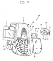
FIG. 3 is a disassembled front perspective view showing the wire communication terminal having an LCD module according to one embodiment of the present invention. -
FIG. 4 is a disassembled rear perspective view showing the wire communication terminal having an LCD module according to one embodiment of the present invention. -
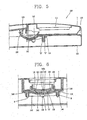
FIG. 5 is a sectional view taken along line I-I inFIG. 2 . -
FIG. 6 is a sectional view taken along line II-II inFIG. 2 . - The wire communication terminal in accordance with one or more embodiments of the present invention provides improved performance because it can be rotated throughout any angle within a predetermined rotation range, not to only a limited or discrete number of preset angles as is the case with related-art terminals having LCD modules.
-
FIG. 2 is a front perspective view showing awire communication terminal 100 having an LCD module according to one embodiment of the present invention. This terminal includes afirst case 110 having amounting portion 111 for mounting anLCD module 1 at one side thereof. Themounting portion 111 is provided with athrough hole 112. - The terminal also includes a
guide member 120, aslide member 130, and acover member 140. Theguide member 120 is fixed to a rear surface of thefirst case 110 so as to be positioned at thethrough hole 112. Theslide member 130 has a circular arc shape and is provided at one side of theLCD module 1, so as to be inserted into thethrough hole 112 and to be slid along a rear surface of theguide member 120. Thecover member 140 has a circular arc shape and is fixed to the rear surface of thefirst case 110, so thatslide member 130 can be slid along the rear surface ofguide member 120. Asecond case 150 may be coupled to thefirst case 110. - In addition to these features, a space portion "S" is formed between
guide member 120 andcover member 140, andslide member 130 is slidably fitted into the space portion S. Guidemember 120,slide member 130, andcover member 140 preferably has the same curvature so thatslide member 130 can be smoothly slid in the space portion S. (See, for example,FIGS. 5 and 6 ) - A
first guide protrusion 121 is formed at both sides of the rear surface ofguide member 120 along a rotation direction of theLCD module 1.Slide protrusion 131 corresponding tofirst guide protrusion 121 is formed at both sides of a front surface of theslide member 130 along the rotation direction of theLCD module 1. (See, e.g.,FIGS. 3 ,4 , and6 .) - A
slide groove 132 is formed at both sides of a rear surface ofslide member 130, and asecond guide protrusion 141 corresponding toslide groove 132 is formed at both sides of a front surface ofcover member 140 along the rotation direction of theLCD module 1. (See, e.g,FIGS. 3 ,4 , and6 .) - A
slide slit 133 for limiting a rotation range of the LCD module is formed in the middle ofslide member 130 along the rotation direction of theLCD module 1, andstopper 142 is formed in the middle of the front surface ofcover member 140 so as to be inserted intoslide slit 133. Aninsertion groove 122 into which is inserted anend 142a ofstopper 142 is formed in the middle ofguide member 120. - A plurality of
bosses 113 having bolt holes H are formed at the rear surface of thefirst case 110, and a plurality ofinsertion portions 144 having bolt holes H are formed at aflange portion 143 of thecover member 140 so as to correspond to thebosses 113. Eachboss 113 is fitted into eachinsertion portion 144 and a bolt B is coupled to the bolt hole H, thereby fixingcover member 140 tofirst case 110. Preferably,guide member 120 andcover member 140 are formed of a lubricating material, especially, polyoxymethylene (POM) such as engineering plastic so that theslide member 130 can be smoothly slid betweenguide member 120 andcover member 140 with a frictional force. - An assembly processes for the wire communication terminal having an LCD module according to the present invention will now be explained. As shown in
FIGS. 3 to 6 , theguide member 120 is located at the rear surface offirst case 110 and the bolt B is coupled to bolt hole H ofguide member 120, thereby couplingguide member 120 tofirst case 110 with a printedcircuit board 101. Under the state,slide member 130 is inserted into throughhole 112 and then is adhered to the rear surface ofguide member 120.Slide protrusions 131 ofslide member 130 comes into contact with respectivefirst guide protrusions 121 ofguide member 120. - Then,
insertion portion 144 ofcover member 140 is coupled toboss 113 formed at the rear surface offirst case 110, and bolt B is coupled to the bolt hole H to thereby fixcover member 140 tofirst case 110. Sincesecond guide protrusions 141 is fitted intorespective slide grooves 132 of the slide member,slide member 130 is slidable within the space portion S formed betweenguide member 120 andcover member 140. Thesecond case 150 is then coupled tofirst case 110 to thereby complete the assembly of the communication device. - Operation of the wire communication terminal of the present invention will now be explained. Referring to
FIG. 2 , when a user wants to control an angle of the LCD module, the user lifts the end of the LCD module in the arrow direction. - As the LCD module is lifted,
slide member 130 fixed to the LCD module is slid within space portion S betweenguide member 120 andcover member 140 Whenslide member 130 is slid,first guide protrusions 121 corresponds torespective slide protrusions 131 ofslide member 130 andsecond guide protrusions 141 corresponds torespective slide grooves 132 ofslide member 130. Accordingly,slide member 130 smoothly slides while maintaining a proper frictional force. - When
slide member 130 is slid to a user's desired position, the user lets slide member 130 (held by his hand) go. Sinceguide member 120 andcover member 140 are formed of polyoxymethylen,slide member 130 smoothly slides. Also, sincefirst guide protrusions 121 corresponds torespective slide protrusions 131 ofslide member 130, andsecond guide protrusions 141 corresponds torespective slide grooves 132 ofslide member 130,slide member 130 is located precisely at the user's desired position, thereby optimizing the viewing resolution of the LCD for each individual user's eye level. - A maximum rotation angle of the LCD module is limited by
stopper 142 fitted into slide slit 133, so that the LCD module is rotated only by a set angle without being rotated too much. Accordingly, users can control the angle of the LCD module fixed to slidemember 130 simply and conveniently. - In summary, the angle of the LCD module of the wire communication terminal of the present invention conveniently and simply controlled by users, and at the same time improves resolution of the LCD module for viewing. Also, since the angle of the LCD module is freely controlled simply, the productivity is enhanced.
Claims (11)
- A wire communication terminal having an LCD module (1), comprising:- a first case (110) having a mounting portion (111) for rotatably mounting an LCD module (1) at one side thereof within a predetermined range of rotation, the mounting portion (111) provided with a through hole (112);characterized by- a guide member (120) fixed to a rear surface of the first case (111) so as to be located at the through hole (112);- a cover member (140) having a circular arc shape and fixed to the rear surface of the first case so as to form a space portion (S) between the guide member (120) and the cover member (140);- a slide member (130) having a circular arc shape and provided at one side of the LCD module (1), so as to be inserted into the through hole (112), said slide member (130) being inserted into the space portion (S), wherein the cover member (140) and the slide member (130) have the same shape and wherein the slide member (130) slides along a rear surface of the guide member (120); and- a second case (150) coupled to the first case (110).
- The terminal of claim 1, further comprising:- a respective first guide protrusion (121) formed at both sides of a rear surface of the guide member (120) along a rotation direction of the LCD module (1),- slide protrusions (131) corresponding to said first guide protrusions (121) formed at both sides of a front surface of the slide member (130) along the rotation direction of the LCD module (1),- a respective slide groove (132) formed at both sides of a rear surface of the slide member (130), and- second guide protrusions (141) corresponding to said slide grooves (132) formed at both sides of a front surface of the cover member (140) along the rotation direction of the LCD module (1).
- The terminal of claim 2, further comprising:- a slide slit (133) limiting a rotation range of the LCD module (1), the slide slit (133) being formed in a middle of the slide member (130) along the rotation direction of the LCD module (1); and- a stopper (142) formed in the middle of the front surface of the cover member (140) so as to be inserted into the slide slit (133).
- The terminal of claim 3, further comprising:- an insertion groove (122), formed in the middle of the guide member (120), into which an end of the stopper (142) is inserted.
- The terminal of claim 1, wherein the first case (110) includes a plurality of bosses (113) having bolt holes (H) at the rear surface thereof, and- a plurality of insertion portions (144) having bolt holes (H) formed at a flange portion (143) of the cover member (140) so as to correspond to the bosses (113).
- The terminal of claim 5, wherein the bosses (113) are fitted into the insertion portions (144), and a bolt (B) is coupled to the respective bolt hole (H).
- The terminal of claim 1, wherein the guide member (120) and the cover member (140) are formed of a lubricating material.
- The terminal of claim 7, wherein the guide member (120) and the cover member (140) are formed of polyoxymethylene.
- The terminal of claim 1, wherein the guide member (120), cover member (140), and slide member (130) have a same curvature to thereby allow the slide member (130) to smoothly slide in the space portion (S).
- The terminal of claim 1, wherein said same shape is a circular arc shape.
- The terminal of claim 1, wherein a flange portion of the guide member (120) is coupled to the first case (110) with a printed circuit board (101).
Applications Claiming Priority (1)
| Application Number | Priority Date | Filing Date | Title |
|---|---|---|---|
| KR1020050040572A KR100703901B1 (en) | 2005-05-16 | 2005-05-16 | LCD module rotating device for stepless angle adjustment |
Publications (2)
| Publication Number | Publication Date |
|---|---|
| EP1724993A1 EP1724993A1 (en) | 2006-11-22 |
| EP1724993B1 true EP1724993B1 (en) | 2014-03-05 |
Family
ID=36586139
Family Applications (1)
| Application Number | Title | Priority Date | Filing Date |
|---|---|---|---|
| EP06009238.4A Expired - Lifetime EP1724993B1 (en) | 2005-05-16 | 2006-05-04 | Wire communication terminal having LCD module |
Country Status (5)
| Country | Link |
|---|---|
| US (1) | US7564965B2 (en) |
| EP (1) | EP1724993B1 (en) |
| KR (1) | KR100703901B1 (en) |
| CN (1) | CN1866987B (en) |
| ES (1) | ES2456055T3 (en) |
Families Citing this family (1)
| Publication number | Priority date | Publication date | Assignee | Title |
|---|---|---|---|---|
| CN101771199B (en) * | 2009-01-06 | 2012-09-05 | 华硕电脑股份有限公司 | Screw-type electrical connection device and slide-type electronic device |
Family Cites Families (7)
| Publication number | Priority date | Publication date | Assignee | Title |
|---|---|---|---|---|
| US4989167A (en) * | 1989-09-11 | 1991-01-29 | Jeffrey Kapec | Desktop computer terminal having an angularly adjustable electronic display module |
| CH683658A5 (en) | 1991-03-12 | 1994-04-15 | Siemens Ag Albis | Position mover for section linked to carrier, e.g. information display - uses guide rail on at least one side of movable part engaging guide groove in support having braking element |
| US5583744A (en) * | 1994-09-06 | 1996-12-10 | Citizen Watch Co., Ltd. | Portable computer with detachable battery pack |
| WO1996029809A1 (en) | 1995-03-21 | 1996-09-26 | Siemens Rolm Communications Inc. | An interconnection mechanism for a tiltable telephone display unit |
| JP3588702B2 (en) * | 1995-04-03 | 2004-11-17 | Necインフロンティア株式会社 | Mounting device for variable elevation angle members in information processing terminals |
| KR20030000598A (en) * | 2001-06-26 | 2003-01-06 | 주식회사 하이닉스반도체 | A charge coupled device |
| KR100542354B1 (en) * | 2003-10-13 | 2006-01-10 | 삼성전자주식회사 | Electronic device with improved hinge |
-
2005
- 2005-05-16 KR KR1020050040572A patent/KR100703901B1/en not_active Expired - Fee Related
-
2006
- 2006-04-27 US US11/411,841 patent/US7564965B2/en not_active Expired - Fee Related
- 2006-05-04 EP EP06009238.4A patent/EP1724993B1/en not_active Expired - Lifetime
- 2006-05-04 ES ES06009238.4T patent/ES2456055T3/en not_active Expired - Lifetime
- 2006-05-16 CN CN2006100818006A patent/CN1866987B/en not_active Expired - Fee Related
Also Published As
| Publication number | Publication date |
|---|---|
| US7564965B2 (en) | 2009-07-21 |
| CN1866987A (en) | 2006-11-22 |
| CN1866987B (en) | 2012-04-04 |
| US20060268188A1 (en) | 2006-11-30 |
| EP1724993A1 (en) | 2006-11-22 |
| KR100703901B1 (en) | 2007-04-06 |
| KR20060118104A (en) | 2006-11-23 |
| ES2456055T3 (en) | 2014-04-21 |
Similar Documents
| Publication | Publication Date | Title |
|---|---|---|
| EP1515525B1 (en) | Slide assembly for mobile communication device | |
| US6781821B2 (en) | Electronic apparatus | |
| WO2002089343A1 (en) | Hinge device | |
| US6947778B2 (en) | Handheld electronic device | |
| US10444449B2 (en) | Optical transceiver | |
| US7046264B2 (en) | Electronic device having display unit | |
| US7564965B2 (en) | Wire communication terminal having LCD module | |
| US8090096B2 (en) | Tilting mechanism and electronic apparatus | |
| KR20020065702A (en) | Folder type mobile communication terminal | |
| JP6386504B2 (en) | Name plate mounting structure | |
| KR101029809B1 (en) | Slide type mobile terminal | |
| KR20250078951A (en) | head mounted display | |
| JP2009284017A (en) | Electronic apparatus equipped with display unit | |
| JP4461033B2 (en) | Switch device | |
| US20130033161A1 (en) | Sliding mechanism and portable device | |
| JP4360219B2 (en) | LED lens mounting structure | |
| JP2008138689A (en) | Connecting device | |
| JP2007004592A (en) | Electronics | |
| KR100568219B1 (en) | Display device | |
| KR20020072828A (en) | Hinge device | |
| US6811332B2 (en) | Apparatus having push-operatable operation member, and camera | |
| KR100735240B1 (en) | Adjusting the angle of rotation of the LCD housing on the phone | |
| JP3805092B2 (en) | Elastic engagement structure | |
| KR20040036005A (en) | Device for stand to combination of LCD monitor | |
| KR100677340B1 (en) | Slide type mobile communication terminal with movable LCD |
Legal Events
| Date | Code | Title | Description |
|---|---|---|---|
| PUAI | Public reference made under article 153(3) epc to a published international application that has entered the european phase |
Free format text: ORIGINAL CODE: 0009012 |
|
| AK | Designated contracting states |
Kind code of ref document: A1 Designated state(s): AT BE BG CH CY CZ DE DK EE ES FI FR GB GR HU IE IS IT LI LT LU LV MC NL PL PT RO SE SI SK TR |
|
| AX | Request for extension of the european patent |
Extension state: AL BA HR MK YU |
|
| 17P | Request for examination filed |
Effective date: 20070518 |
|
| 17Q | First examination report despatched |
Effective date: 20070615 |
|
| AKX | Designation fees paid |
Designated state(s): AT BE BG CH CY CZ DE DK EE ES FI FR GB GR HU IE IS IT LI LT LU LV MC NL PL PT RO SE SI SK TR |
|
| RAP1 | Party data changed (applicant data changed or rights of an application transferred) |
Owner name: LG-ERICSSON CO., LTD. |
|
| GRAP | Despatch of communication of intention to grant a patent |
Free format text: ORIGINAL CODE: EPIDOSNIGR1 |
|
| INTG | Intention to grant announced |
Effective date: 20130911 |
|
| RAP1 | Party data changed (applicant data changed or rights of an application transferred) |
Owner name: ERICSSON-LG CO., LTD. |
|
| GRAS | Grant fee paid |
Free format text: ORIGINAL CODE: EPIDOSNIGR3 |
|
| GRAA | (expected) grant |
Free format text: ORIGINAL CODE: 0009210 |
|
| RAP1 | Party data changed (applicant data changed or rights of an application transferred) |
Owner name: ERICSSON-LG ENTERPRISE CO., LTD. |
|
| AK | Designated contracting states |
Kind code of ref document: B1 Designated state(s): AT BE BG CH CY CZ DE DK EE ES FI FR GB GR HU IE IS IT LI LT LU LV MC NL PL PT RO SE SI SK TR |
|
| REG | Reference to a national code |
Ref country code: GB Ref legal event code: FG4D |
|
| REG | Reference to a national code |
Ref country code: CH Ref legal event code: EP |
|
| REG | Reference to a national code |
Ref country code: AT Ref legal event code: REF Ref document number: 655521 Country of ref document: AT Kind code of ref document: T Effective date: 20140315 |
|
| REG | Reference to a national code |
Ref country code: IE Ref legal event code: FG4D |
|
| REG | Reference to a national code |
Ref country code: DE Ref legal event code: R096 Ref document number: 602006040457 Country of ref document: DE Effective date: 20140417 |
|
| REG | Reference to a national code |
Ref country code: ES Ref legal event code: FG2A Ref document number: 2456055 Country of ref document: ES Kind code of ref document: T3 Effective date: 20140421 |
|
| REG | Reference to a national code |
Ref country code: SE Ref legal event code: TRGR |
|
| REG | Reference to a national code |
Ref country code: AT Ref legal event code: MK05 Ref document number: 655521 Country of ref document: AT Kind code of ref document: T Effective date: 20140305 |
|
| REG | Reference to a national code |
Ref country code: NL Ref legal event code: VDEP Effective date: 20140305 |
|
| PG25 | Lapsed in a contracting state [announced via postgrant information from national office to epo] |
Ref country code: LT Free format text: LAPSE BECAUSE OF FAILURE TO SUBMIT A TRANSLATION OF THE DESCRIPTION OR TO PAY THE FEE WITHIN THE PRESCRIBED TIME-LIMIT Effective date: 20140305 |
|
| REG | Reference to a national code |
Ref country code: LT Ref legal event code: MG4D |
|
| PG25 | Lapsed in a contracting state [announced via postgrant information from national office to epo] |
Ref country code: CY Free format text: LAPSE BECAUSE OF FAILURE TO SUBMIT A TRANSLATION OF THE DESCRIPTION OR TO PAY THE FEE WITHIN THE PRESCRIBED TIME-LIMIT Effective date: 20140305 Ref country code: FI Free format text: LAPSE BECAUSE OF FAILURE TO SUBMIT A TRANSLATION OF THE DESCRIPTION OR TO PAY THE FEE WITHIN THE PRESCRIBED TIME-LIMIT Effective date: 20140305 Ref country code: AT Free format text: LAPSE BECAUSE OF FAILURE TO SUBMIT A TRANSLATION OF THE DESCRIPTION OR TO PAY THE FEE WITHIN THE PRESCRIBED TIME-LIMIT Effective date: 20140305 |
|
| PG25 | Lapsed in a contracting state [announced via postgrant information from national office to epo] |
Ref country code: LV Free format text: LAPSE BECAUSE OF FAILURE TO SUBMIT A TRANSLATION OF THE DESCRIPTION OR TO PAY THE FEE WITHIN THE PRESCRIBED TIME-LIMIT Effective date: 20140305 |
|
| PG25 | Lapsed in a contracting state [announced via postgrant information from national office to epo] |
Ref country code: CZ Free format text: LAPSE BECAUSE OF FAILURE TO SUBMIT A TRANSLATION OF THE DESCRIPTION OR TO PAY THE FEE WITHIN THE PRESCRIBED TIME-LIMIT Effective date: 20140305 Ref country code: BG Free format text: LAPSE BECAUSE OF FAILURE TO SUBMIT A TRANSLATION OF THE DESCRIPTION OR TO PAY THE FEE WITHIN THE PRESCRIBED TIME-LIMIT Effective date: 20140605 Ref country code: NL Free format text: LAPSE BECAUSE OF FAILURE TO SUBMIT A TRANSLATION OF THE DESCRIPTION OR TO PAY THE FEE WITHIN THE PRESCRIBED TIME-LIMIT Effective date: 20140305 Ref country code: RO Free format text: LAPSE BECAUSE OF FAILURE TO SUBMIT A TRANSLATION OF THE DESCRIPTION OR TO PAY THE FEE WITHIN THE PRESCRIBED TIME-LIMIT Effective date: 20140305 Ref country code: IS Free format text: LAPSE BECAUSE OF FAILURE TO SUBMIT A TRANSLATION OF THE DESCRIPTION OR TO PAY THE FEE WITHIN THE PRESCRIBED TIME-LIMIT Effective date: 20140705 Ref country code: EE Free format text: LAPSE BECAUSE OF FAILURE TO SUBMIT A TRANSLATION OF THE DESCRIPTION OR TO PAY THE FEE WITHIN THE PRESCRIBED TIME-LIMIT Effective date: 20140305 Ref country code: BE Free format text: LAPSE BECAUSE OF FAILURE TO SUBMIT A TRANSLATION OF THE DESCRIPTION OR TO PAY THE FEE WITHIN THE PRESCRIBED TIME-LIMIT Effective date: 20140305 |
|
| PG25 | Lapsed in a contracting state [announced via postgrant information from national office to epo] |
Ref country code: SK Free format text: LAPSE BECAUSE OF FAILURE TO SUBMIT A TRANSLATION OF THE DESCRIPTION OR TO PAY THE FEE WITHIN THE PRESCRIBED TIME-LIMIT Effective date: 20140305 Ref country code: PL Free format text: LAPSE BECAUSE OF FAILURE TO SUBMIT A TRANSLATION OF THE DESCRIPTION OR TO PAY THE FEE WITHIN THE PRESCRIBED TIME-LIMIT Effective date: 20140305 |
|
| REG | Reference to a national code |
Ref country code: DE Ref legal event code: R097 Ref document number: 602006040457 Country of ref document: DE |
|
| PG25 | Lapsed in a contracting state [announced via postgrant information from national office to epo] |
Ref country code: LU Free format text: LAPSE BECAUSE OF FAILURE TO SUBMIT A TRANSLATION OF THE DESCRIPTION OR TO PAY THE FEE WITHIN THE PRESCRIBED TIME-LIMIT Effective date: 20140504 Ref country code: PT Free format text: LAPSE BECAUSE OF FAILURE TO SUBMIT A TRANSLATION OF THE DESCRIPTION OR TO PAY THE FEE WITHIN THE PRESCRIBED TIME-LIMIT Effective date: 20140707 |
|
| REG | Reference to a national code |
Ref country code: CH Ref legal event code: PL |
|
| PLBE | No opposition filed within time limit |
Free format text: ORIGINAL CODE: 0009261 |
|
| STAA | Information on the status of an ep patent application or granted ep patent |
Free format text: STATUS: NO OPPOSITION FILED WITHIN TIME LIMIT |
|
| PG25 | Lapsed in a contracting state [announced via postgrant information from national office to epo] |
Ref country code: LI Free format text: LAPSE BECAUSE OF NON-PAYMENT OF DUE FEES Effective date: 20140531 Ref country code: MC Free format text: LAPSE BECAUSE OF FAILURE TO SUBMIT A TRANSLATION OF THE DESCRIPTION OR TO PAY THE FEE WITHIN THE PRESCRIBED TIME-LIMIT Effective date: 20140305 Ref country code: DK Free format text: LAPSE BECAUSE OF FAILURE TO SUBMIT A TRANSLATION OF THE DESCRIPTION OR TO PAY THE FEE WITHIN THE PRESCRIBED TIME-LIMIT Effective date: 20140305 Ref country code: CH Free format text: LAPSE BECAUSE OF NON-PAYMENT OF DUE FEES Effective date: 20140531 |
|
| 26N | No opposition filed |
Effective date: 20141208 |
|
| REG | Reference to a national code |
Ref country code: IE Ref legal event code: MM4A |
|
| REG | Reference to a national code |
Ref country code: FR Ref legal event code: ST Effective date: 20150130 |
|
| REG | Reference to a national code |
Ref country code: DE Ref legal event code: R097 Ref document number: 602006040457 Country of ref document: DE Effective date: 20141208 |
|
| PG25 | Lapsed in a contracting state [announced via postgrant information from national office to epo] |
Ref country code: IE Free format text: LAPSE BECAUSE OF NON-PAYMENT OF DUE FEES Effective date: 20140504 |
|
| PG25 | Lapsed in a contracting state [announced via postgrant information from national office to epo] |
Ref country code: SI Free format text: LAPSE BECAUSE OF FAILURE TO SUBMIT A TRANSLATION OF THE DESCRIPTION OR TO PAY THE FEE WITHIN THE PRESCRIBED TIME-LIMIT Effective date: 20140305 Ref country code: FR Free format text: LAPSE BECAUSE OF NON-PAYMENT OF DUE FEES Effective date: 20140602 |
|
| PG25 | Lapsed in a contracting state [announced via postgrant information from national office to epo] |
Ref country code: GR Free format text: LAPSE BECAUSE OF FAILURE TO SUBMIT A TRANSLATION OF THE DESCRIPTION OR TO PAY THE FEE WITHIN THE PRESCRIBED TIME-LIMIT Effective date: 20140606 |
|
| PG25 | Lapsed in a contracting state [announced via postgrant information from national office to epo] |
Ref country code: HU Free format text: LAPSE BECAUSE OF FAILURE TO SUBMIT A TRANSLATION OF THE DESCRIPTION OR TO PAY THE FEE WITHIN THE PRESCRIBED TIME-LIMIT; INVALID AB INITIO Effective date: 20060504 Ref country code: TR Free format text: LAPSE BECAUSE OF FAILURE TO SUBMIT A TRANSLATION OF THE DESCRIPTION OR TO PAY THE FEE WITHIN THE PRESCRIBED TIME-LIMIT Effective date: 20140305 |
|
| PGFP | Annual fee paid to national office [announced via postgrant information from national office to epo] |
Ref country code: GB Payment date: 20170420 Year of fee payment: 12 Ref country code: DE Payment date: 20170420 Year of fee payment: 12 |
|
| PGFP | Annual fee paid to national office [announced via postgrant information from national office to epo] |
Ref country code: SE Payment date: 20170421 Year of fee payment: 12 Ref country code: ES Payment date: 20170619 Year of fee payment: 12 Ref country code: IT Payment date: 20170518 Year of fee payment: 12 |
|
| REG | Reference to a national code |
Ref country code: DE Ref legal event code: R119 Ref document number: 602006040457 Country of ref document: DE |
|
| REG | Reference to a national code |
Ref country code: SE Ref legal event code: EUG |
|
| GBPC | Gb: european patent ceased through non-payment of renewal fee |
Effective date: 20180504 |
|
| PG25 | Lapsed in a contracting state [announced via postgrant information from national office to epo] |
Ref country code: SE Free format text: LAPSE BECAUSE OF NON-PAYMENT OF DUE FEES Effective date: 20180505 |
|
| PG25 | Lapsed in a contracting state [announced via postgrant information from national office to epo] |
Ref country code: DE Free format text: LAPSE BECAUSE OF NON-PAYMENT OF DUE FEES Effective date: 20181201 Ref country code: IT Free format text: LAPSE BECAUSE OF NON-PAYMENT OF DUE FEES Effective date: 20180504 Ref country code: GB Free format text: LAPSE BECAUSE OF NON-PAYMENT OF DUE FEES Effective date: 20180504 |
|
| REG | Reference to a national code |
Ref country code: ES Ref legal event code: FD2A Effective date: 20190913 |
|
| PG25 | Lapsed in a contracting state [announced via postgrant information from national office to epo] |
Ref country code: ES Free format text: LAPSE BECAUSE OF NON-PAYMENT OF DUE FEES Effective date: 20180505 |