EP1724456A1 - Device for multiple regulation having sliding members, and intake manifold comprising a device of this type - Google Patents
Device for multiple regulation having sliding members, and intake manifold comprising a device of this type Download PDFInfo
- Publication number
- EP1724456A1 EP1724456A1 EP06114204A EP06114204A EP1724456A1 EP 1724456 A1 EP1724456 A1 EP 1724456A1 EP 06114204 A EP06114204 A EP 06114204A EP 06114204 A EP06114204 A EP 06114204A EP 1724456 A1 EP1724456 A1 EP 1724456A1
- Authority
- EP
- European Patent Office
- Prior art keywords
- shutter
- diaphragm
- cylinder head
- mounting plate
- sliding
- Prior art date
- Legal status (The legal status is an assumption and is not a legal conclusion. Google has not performed a legal analysis and makes no representation as to the accuracy of the status listed.)
- Granted
Links
Images


Classifications
-
- F—MECHANICAL ENGINEERING; LIGHTING; HEATING; WEAPONS; BLASTING
- F02—COMBUSTION ENGINES; HOT-GAS OR COMBUSTION-PRODUCT ENGINE PLANTS
- F02M—SUPPLYING COMBUSTION ENGINES IN GENERAL WITH COMBUSTIBLE MIXTURES OR CONSTITUENTS THEREOF
- F02M35/00—Combustion-air cleaners, air intakes, intake silencers, or induction systems specially adapted for, or arranged on, internal-combustion engines
- F02M35/10—Air intakes; Induction systems
- F02M35/10006—Air intakes; Induction systems characterised by the position of elements of the air intake system in direction of the air intake flow, i.e. between ambient air inlet and supply to the combustion chamber
- F02M35/10078—Connections of intake systems to the engine
- F02M35/10085—Connections of intake systems to the engine having a connecting piece, e.g. a flange, between the engine and the air intake being foreseen with a throttle valve, fuel injector, mixture ducts or the like
-
- F—MECHANICAL ENGINEERING; LIGHTING; HEATING; WEAPONS; BLASTING
- F02—COMBUSTION ENGINES; HOT-GAS OR COMBUSTION-PRODUCT ENGINE PLANTS
- F02D—CONTROLLING COMBUSTION ENGINES
- F02D9/00—Controlling engines by throttling air or fuel-and-air induction conduits or exhaust conduits
- F02D9/08—Throttle valves specially adapted therefor; Arrangements of such valves in conduits
- F02D9/12—Throttle valves specially adapted therefor; Arrangements of such valves in conduits having slidably-mounted valve members; having valve members movable longitudinally of conduit
- F02D9/14—Throttle valves specially adapted therefor; Arrangements of such valves in conduits having slidably-mounted valve members; having valve members movable longitudinally of conduit the members being slidable transversely of conduit
-
- F—MECHANICAL ENGINEERING; LIGHTING; HEATING; WEAPONS; BLASTING
- F02—COMBUSTION ENGINES; HOT-GAS OR COMBUSTION-PRODUCT ENGINE PLANTS
- F02M—SUPPLYING COMBUSTION ENGINES IN GENERAL WITH COMBUSTIBLE MIXTURES OR CONSTITUENTS THEREOF
- F02M35/00—Combustion-air cleaners, air intakes, intake silencers, or induction systems specially adapted for, or arranged on, internal-combustion engines
- F02M35/10—Air intakes; Induction systems
- F02M35/10091—Air intakes; Induction systems characterised by details of intake ducts: shapes; connections; arrangements
- F02M35/10111—Substantially V-, C- or U-shaped ducts in direction of the flow path
-
- F—MECHANICAL ENGINEERING; LIGHTING; HEATING; WEAPONS; BLASTING
- F02—COMBUSTION ENGINES; HOT-GAS OR COMBUSTION-PRODUCT ENGINE PLANTS
- F02M—SUPPLYING COMBUSTION ENGINES IN GENERAL WITH COMBUSTIBLE MIXTURES OR CONSTITUENTS THEREOF
- F02M35/00—Combustion-air cleaners, air intakes, intake silencers, or induction systems specially adapted for, or arranged on, internal-combustion engines
- F02M35/10—Air intakes; Induction systems
- F02M35/104—Intake manifolds
- F02M35/112—Intake manifolds for engines with cylinders all in one line
Definitions
- the present invention relates to the field of the regulation of gas streams, more precisely the regulation of the gas stream injected into the cylinders of an internal-combustion engine.
- the invention relates, more particularly, to a device for multiple regulation of the gas stream delivered by the various pipes of an intake manifold, and also to a manifold comprising a device of this type.
- the gas stream in a conduit may be regulated in various ways and by means of various members, in particular rotary members.
- a known solution which is advantageous in terms of the overall size and simplicity of the construction, consists in using a sliding shutter-type regulating member.
- One cost-effective solution consists in making the movable regulating members from a thermoplastic material.
- the aim of the present invention is to overcome at least some of the abovementioned problems.
- the invention accordingly relates to a device for multiple regulation of the gas stream passing through pipes of an intake manifold in the inlets of the cylinder head of an internal-combustion engine, the manifold being joined to said cylinder head by a mounting plate having a substantially planar structure, at least in the region of its side that is intended to enter into contact with said cylinder head, extending in the region of the ends of said pipes and mechanically interconnecting said pipes, device characterised in that it comprises, for each pipe, on the one hand, a conduit portion extending in a leak proof manner said pipe in the region of its outlet through the thickness of said mounting plate and connecting fluidly this pipe to the corresponding inlet in the cylinder head and, on the other hand, a sliding shutter or diaphragm, which is capable of being displaced between a first end position, in which it partially closes the passage in the conduit portion associated with the pipe in question, and a second end position, in which it completely clears the passage in said conduit portion, and in that said shutters or diaphragms are
- Figures 1, 4 to 7 and 8 show a device for multiple regulation of the gas stream passing through the pipes 1' of an intake manifold 1 into or toward the inlets in the cylinder head 2' of an internal-combustion engine, the manifold being joined to said cylinder head 2' by a mounting plate 2 having a substantially planar structure, at least in the region of its side that is intended to enter into contact with said cylinder head 2', extending in the region of the ends of said pipes 1' and mechanically interconnecting said pipes.
- this regulating device comprises, for each pipe 1', on the one hand, a conduit portion 3 extending in a leak proof manner said pipe 1' in the region of its outlet through the thickness of said mounting plate 2 and connecting fluidly this pipe 1' to the corresponding inlet in the cylinder head 2' and, on the other hand, a sliding shutter or diaphragm 5, which is capable of being displaced between a first end position, in which it partially closes the passage in the conduit portion 3 associated with the pipe 1' in question, and a second end position, in which it completely clears the passage in said conduit portion 3. Furthermore, said shutters or diaphragms 5 are mounted and guided, each with a predetermined clearance, in a support and guide structure provided or attached in said plate 2 and comprising two opposing guide rails or guide rail portions 6 and 7.
- the mounting plate 2 which has, for example, an elongate rectangular shape, preferably has a predetermined thickness defined by a circumferential or lateral delimitation wall 4, defining an edge 4' that is intimately applied against the face of the cylinder head 2' having the inlets, and said shutters or diaphragms 5 are located in the thickness of said plate 2, extending and sliding substantially in the plane thereof, and are set sliding by a common control rod 8. Moreover, said shutters or diaphragms 5 are guided in translation by pairs of guide rail segments 6 and 7, all of which define a single direction of sliding by translation.
- each of the shutters or diaphragms 5 is guided independently, over the entire length of its displacement course, within the mounting plate itself, without entering into contact with the cylinder head 2'.
- said shutters or diaphragms 5 are mounted inside the plate 2, any problems of tightness between the environment for mounting said shutters and the external environment are overcome by the confinement chamber provided by the wall 4, said plate 2 being, of course, closed on its face opposing the edge 4' (around outlets in the pipes 1' and fixing eyelets 13).
- said shutters or diaphragms 5 all extend and slide in a single plane perpendicular to the direction of circulation of the gas streams into the conduit portions 3, and are driven in translation by a common control rod 8 in the form of a control rod or bar mechanically coupled to said shutters 5 and displaced in translation in its longitudinal direction by an operating member 9 such as, for example, a rotary shaft connected to said control rod by a rotating slider crank system.
- each shutter or diaphragm 5 has a planar and one-piece general structure, consisting mainly of a first part 5' having an external shape and a surface extension enabling it to close a part 3' of the passage of the conduit portion 3 associated therewith, and of a second part 5" forming an interface for coupling to the common control rod 8, each of said shutter parts 5' and 5" comprising a wall edge segment 10, 11, for example in the form of a profiled wing or shoulder, cooperating by mutual engagement with a respective profiled guide rail segment 6, 7 over the entire length of the limited sliding course of said shutter 5, thus providing a sliding contact guided in the direction of sliding, the wall edge segments 10 and 11 of the first and second shutter parts 5' and 5", like the rail portions 6 and 7 respectively cooperating with these parts, being mutually parallel.
- first part 5' in particular, of each shutter 5 will depend on the surface area of the section of the passage part 3' of the conduit portion 3 to be closed and on the space available for its mounting and its displacement between its two sliding end positions.
- each shutter 5 exhibits a, preferably solid, plate-like structure and large longitudinal dimensions in the region of the wall edges comprising the segments 10 and 11, in order to provide precise and resistant linear guidance over a substantial length.
- the shutters may be of various shapes, depending on the overall size requirements, though efforts will nevertheless be made to standardise their shape (streamlined production).
- the rail portions 6 and 7, like the lateral segments 10 and 11 of the shutters 5 guided in these rail portions, may or may not be coplanar.
- the rail portions 7 may, in particular, extend laterally along the groove portions 18, either in proximity to the base of said groove portions (figure 4) or in proximity to, or in the region of, the longitudinal opening in said groove portions (figures 2 and 5 to 7).
- the segments 11 may be in the form of ribs and, in the second case, in the form of shoulders.
- the shutters or diaphragms 5 are located in the region of the ends of the conduit portions 3 that are intended to face the inlets in the cylinder head 2', said shutters or diaphragms 5 being located in part between these ends and said inlets in the closed position of said device for multiple regulation.
- the plate 2 is advantageously produced by injection-moulding thermoplastic material.
- the conduit portions 3 are formed in one piece with the circumferential or lateral delimitation wall 4 of the mounting plate 2 and are connected to this circumferential wall 4 by connection wall portions 12, some of which may advantageously help to guide the sliding shutters or diaphragms 5, said mounting plate 4 also incorporating tubular eyelets 13 for receiving sleeves 13' and/or for the passage of fixing screws or the like, which eyelets are also formed in one piece with the wall 4.
- the support and guide structure assembly may thus be formed in one piece with the plate 2.
- the support and guide structure which incorporates, in particular, the guide rail portions 6 and 7, consists of a separate component 26 attached within the thickness of the mounting plate 2, this component 26 also incorporating the conduit portions 3 that are intended to connect the pipes 1' to the corresponding inlets in the cylinder head 2' and having the general form of a perforated plate of suitable configuration, accommodated within the thickness of the mounting plate 2 and sandwiched with pinching between said plate and the cylinder head 2' after the assembly thereof (in the manner of an insert).
- the edge of the end of each conduit portion 3 that is intended to face an inlet in the cylinder head 2' consists, viewed circumferentially or along the periphery of said edge, of two adjacent edge parts 14, 14', i.e., on the one hand, a first, protruding part 14, which is intended to enter into contact with the edge of the corresponding inlet in the cylinder head 2' and preferably ends in the plane that also contains the end or the edge 4' of the circumferential or lateral delimitation wall 4 of the mounting plate 2 that enters into contact with the cylinder head 2', and, on the other hand, a second, recessed part 14', which circumferentially delimits the part 3' of the passage of the conduit portion 3 that is locked by the associated shutter or diaphragm 5 in the end closure position thereof and is extended by a planar wall portion 15 defining a surface 15' that is swept at least by the first part 5' of the shutter or diaphragm 5 during its displacement between
- the surface 15' that is swept by the first part 5' of the shutter or diaphragm 5, and optionally by a portion of the second part 5" thereof, is laterally delimited, in the region of its outer contour, by a rib or a similar protruding wall portion 16 that is connected to the protruding part 14 of the edge of the end of the conduit portion 3 in question, so as to define a confined space in the region of the interface between this conduit portion 3 and the corresponding inlet in the cylinder head 2' when the mounting plate 2 is attached to said cylinder head, said space being nevertheless open in places, on the side facing the control rod 8, for the passage of a portion for connecting to the second part 5" of the shutter or diaphragm 5, the confinement rib 16 preferably ending in the plane containing the edge 4' of the circumferential wall 4 of the plate 2.
- the rib 16 that laterally delimits the surface 15 ⁇ that is swept by at least the first part 5' of the shutter or diaphragm 5 in question advantageously comprises, in the region of a rectilinear segment that is oriented in the direction of sliding of the shutters or diaphragms 5 and is located facing a rectilinear wall edge segment 10 of the first part 5' of said shutter or diaphragm 5, a lateral shoulder or wing 17 defining for said wall edge segment 10 of said shutter or diaphragm 5 a guide rail portion 6, if necessary in cooperation with the wall portion 15, the rib 16 optionally providing opposing stops for the shutter or diaphragm 5 in question in its two sliding end positions.
- the guide rail portion 6 may be in the form of a groove 6 that is offset relative to the surface 15', i.e. in the form of a groove formed between the wall portion 15 and the shoulder or wing 17.
- the rectangularly-shaped mounting plate 2 comprises, along the inner face of a longitudinal part 4" of its circumferential wall 4, a groove, or preferably a plurality of aligned groove segments 18. Furthermore, the second part 5" of each shutter or diaphragm 5 comprises a runner-type profiled formation 19 that is capable of sliding in a guided manner in the groove or groove segment 18 associated with the shutter or diaphragm in question and has a site 20 for receiving the control rod 8, with partial mutual engagement and locking in the direction of translation.
- said longitudinal part 4" of the circumferential wall 4 comprises, in the region of its inner face and along said groove or each of said groove segments 18, a lateral shoulder or wing 21 defining a guide rail portion 7, which cooperates with a wall edge segment 11 of the profiled formation 19 of the second part 5" of the shutter or diaphragm 5 in question.
- the reception site 20 may, for example, consist of a groove portion provided longitudinally in the profiled runner 19, with a section corresponding to the rod 8.
- the mechanical translation coupling may, for example, be obtained by the provision of lugs on said rod, which lugs are capable of being introduced into orifices provided in the runners 19 (see figure 5).
- guide bearings 18" may be provided in the plate body.
- the lateral shoulder or wing 17 of the rectilinear segment of the rib 16 laterally delimiting the surface 15' that is swept by at least the first part 5' of a shutter or diaphragm 5, which forms a guide rail portion 6 for this first part 5', comprises an incision 22.
- the groove segment 18 forming a guide rail portion 7 comprises a part 18' that is inclined relative to the direction of sliding, such that the shutter or diaphragm 5 in question may be mounted in the guide rail portions 6 and 7 by being suitably inclined relative to said direction of sliding or direction of extension of said guide rail portions 6 and 7.
- Incisions 22' may optionally also be provided in the shoulder or wing 21, as a function of the shape of the second part 5" of the shutters 5.
- each conduit portion 3 is subdivided, in the direction of flow of the stream, substantially into two passages 3' and 3" by a wing or a similar partition portion 23 having a free end, only one 3' of the two passages 3', 3" being closed by the corresponding shutter or diaphragm 5 in the first end position thereof, said wall or wing 23 comprising a recess in the region of the outlet in the conduit portion 3 in question, which recess is defined by a first zone 23', which is adjacent to and level with the first, protruding part 14 of the edge of the end in question of said conduit portion 3, and by a second zone 23", which is adjacent to the second, recessed part 14' of said end edge, the first part 5' of the shutter or diaphragm 5 in question preferably entering into abutment in the region of said recess 23', 23" in the end closure position.
- the wall of the conduit portion 3 may exhibit a local deformation toward the exterior so as to create an additional passage section that is capable of receiving an injector.
- the shutters or diaphragms 5 are guided with at least a minimum clearance, preferably a clearance between a lower value and an upper value, on the one hand, in the plane perpendicular to the direction of sliding, in particular in the direction perpendicular to the plane of the mounting plate 2, and, on the other hand, in the direction perpendicular both to this last direction and to the direction of sliding.
- the circumferential or lateral delimitation wall 4 of the mounting plate 2 comprises, in the region of its edge 4' that is intended to be applied against the face of the cylinder head 2', a double-walled structure, thus forming a groove 24 receiving a continuous circumferential seal 24', said seal extending, optionally in one piece, into the openings in the tubular eyelets 13 in the form of annular seals 24" (figures 5 to 7).
- annular seals 24" will thus provide, for example, tightness between the sleeves 13' and the face of the cylinder head 2' to which the mounting plate 2 is attached, in particular if the support and guide structure of the shutters 5 is formed in one piece in the plate 2.
- the clearance in the direction perpendicular to the plane of the plate 2 and the shutters 5 will preferably be, after mounting of the plate 2 on the cylinder head 2', between approximately 0.2 mm and 0.8 mm, preferably between 0.3 mm and 0.6 mm, in the first part 5' and the surface 15', on the one hand, and between this first part 5' and the face of the cylinder head 2', on the other hand.
- the material from which the shutters 5 are made may, for example, be PA66GF50Mo and the material from which the plate 2, in particular the guide rails 6 and 5, is made, for example PA6GF35.
- the present invention also relates to an intake manifold 1 having a plurality of pipes 1' for an internal-combustion engine, which manifold is intended to be fixed to the cylinder head 2' of said engine by means of a suitable mounting plate 2, manifold characterised in that it comprises a regulating device as described above, integrated into said fixing plate 2 (figures 1 and 8).
- the body of the mounting plate 2 is formed in one piece with a part of the manifold and/or the pipes, the sliding shutters or diaphragms 5, the control rod 8 of said shutters and optionally also the operating member 9 actuating this rod being joined to said body of said plate by simple assembly.
- the mounting plate 2 consists of a component attached to the pipes 1', for example by vibration welding.
Landscapes
- Engineering & Computer Science (AREA)
- Chemical & Material Sciences (AREA)
- Combustion & Propulsion (AREA)
- Mechanical Engineering (AREA)
- General Engineering & Computer Science (AREA)
- Control Of Throttle Valves Provided In The Intake System Or In The Exhaust System (AREA)
- Actuator (AREA)
- Characterised By The Charging Evacuation (AREA)
Abstract
Description
- The present invention relates to the field of the regulation of gas streams, more precisely the regulation of the gas stream injected into the cylinders of an internal-combustion engine.
- The invention relates, more particularly, to a device for multiple regulation of the gas stream delivered by the various pipes of an intake manifold, and also to a manifold comprising a device of this type.
- The gas stream in a conduit may be regulated in various ways and by means of various members, in particular rotary members.
- In the case of regulation in the region of a multiple fluid communication interface, such as, for example, between the outlets of the pipes and the inlets in the cylinder head of the engine, a known solution, which is advantageous in terms of the overall size and simplicity of the construction, consists in using a sliding shutter-type regulating member.
- Generally, at most only partial closure of the outlet of the pipes is desirable.
- One cost-effective solution consists in making the movable regulating members from a thermoplastic material.
- Nevertheless, a plurality of problems appear during the implementation of such a solution.
- Thus, placing regulating members of this type in the region of the interface between the pipes and the cylinder head causes direct sliding contact of components made of thermoplastic material(s) with a metal surface (the cylinder head), and this produces the problems that are well known in this type of situation.
- Moreover, owing to the accumulated production tolerances of the mounting plate of the pipes and regulating members, which are both made of thermoplastic materials, numerous planimetrical defects occur; these defects cause substantial clearance, and therefore a lack of tightness, between pipes, even with the exterior in the region of the interface between the pipes and the cylinder head.
- In order to overcome these defects, it may be proposed to provide the sliding member or the contacting plate part with seals and/or to reduce the clearances between components.
- However, these solutions are not satisfactory, since they are not reliable over time (wear to the seals caused by friction) and may cause locking of the regulating device (insufficient clearances, which may cause the members to become stuck).
- The aim of the present invention is to overcome at least some of the abovementioned problems.
- The invention accordingly relates to a device for multiple regulation of the gas stream passing through pipes of an intake manifold in the inlets of the cylinder head of an internal-combustion engine, the manifold being joined to said cylinder head by a mounting plate having a substantially planar structure, at least in the region of its side that is intended to enter into contact with said cylinder head, extending in the region of the ends of said pipes and mechanically interconnecting said pipes, device characterised in that it comprises, for each pipe, on the one hand, a conduit portion extending in a leak proof manner said pipe in the region of its outlet through the thickness of said mounting plate and connecting fluidly this pipe to the corresponding inlet in the cylinder head and, on the other hand, a sliding shutter or diaphragm, which is capable of being displaced between a first end position, in which it partially closes the passage in the conduit portion associated with the pipe in question, and a second end position, in which it completely clears the passage in said conduit portion, and in that said shutters or diaphragms are mounted and guided, each with a predetermined clearance, in a support and guide structure provided or attached in said plate and comprising two opposing guide rails or guide rail portions.
- A better understanding of the invention will be facilitated by the following description, which relates to a preferred embodiment, given by way of a nonlimiting example and explained with reference to the accompanying schematic drawings, in which:
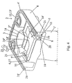
- Figure 1 is a perspective view of an intake manifold provided with a mounting plate equipped with a regulating device according to the invention, the support and guide structure being formed in one piece with said plate;
- Figures 2A and 2B are a front elevation and perspective view, respectively, of the side that is applied to the cylinder head of the body of the mounting plate forming part of the manifold of figure 1, during the mounting of the shutters;
- Figure 3 is a schematic sectional view illustrating the principle of the guiding and sealing implemented by the invention;
- Figure 4 is a perspective and sectional view of a regulating device according to the invention, integrated into the mounting plate;
- Figure 5 is an exploded perspective view showing the various components of the regulating device according to the invention illustrated in figure 1;
- Figures 6 and 7 are a perspective and front elevation view, respectively, of the regulating device integrated into a mounting plate as illustrated in figure 1, the shutters or diaphragms being in the closure end position;
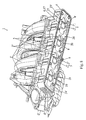
- Figure 8 is a perspective view of an intake manifold provided with a mounting plate equipped with a regulating device according to one variation of the invention, the support and guide structure of the shutters being a separate element attached within said plate;
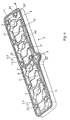
- Figure 9 is a perspective view of the support and guide structure attached within the plate of figure 1; and
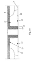
- Figure 10 is a detailed sectional view illustrating the tightness around a tubular eyelet intended to receive a fixing screw.
- Figures 1, 4 to 7 and 8 show a device for multiple regulation of the gas stream passing through the pipes 1' of an
intake manifold 1 into or toward the inlets in the cylinder head 2' of an internal-combustion engine, the manifold being joined to said cylinder head 2' by amounting plate 2 having a substantially planar structure, at least in the region of its side that is intended to enter into contact with said cylinder head 2', extending in the region of the ends of said pipes 1' and mechanically interconnecting said pipes. - According to the invention, this regulating device comprises, for each pipe 1', on the one hand, a
conduit portion 3 extending in a leak proof manner said pipe 1' in the region of its outlet through the thickness of saidmounting plate 2 and connecting fluidly this pipe 1' to the corresponding inlet in the cylinder head 2' and, on the other hand, a sliding shutter ordiaphragm 5, which is capable of being displaced between a first end position, in which it partially closes the passage in theconduit portion 3 associated with the pipe 1' in question, and a second end position, in which it completely clears the passage in saidconduit portion 3. Furthermore, said shutters ordiaphragms 5 are mounted and guided, each with a predetermined clearance, in a support and guide structure provided or attached in saidplate 2 and comprising two opposing guide rails orguide rail portions 6 and 7. - The
mounting plate 2, which has, for example, an elongate rectangular shape, preferably has a predetermined thickness defined by a circumferential orlateral delimitation wall 4, defining an edge 4' that is intimately applied against the face of the cylinder head 2' having the inlets, and said shutters ordiaphragms 5 are located in the thickness ofsaid plate 2, extending and sliding substantially in the plane thereof, and are set sliding by acommon control rod 8. Moreover, said shutters ordiaphragms 5 are guided in translation by pairs ofguide rail segments 6 and 7, all of which define a single direction of sliding by translation. - As a result of these provisions, each of the shutters or
diaphragms 5 is guided independently, over the entire length of its displacement course, within the mounting plate itself, without entering into contact with the cylinder head 2'. Moreover, since said shutters ordiaphragms 5 are mounted inside theplate 2, any problems of tightness between the environment for mounting said shutters and the external environment are overcome by the confinement chamber provided by thewall 4, saidplate 2 being, of course, closed on its face opposing the edge 4' (around outlets in the pipes 1' and fixing eyelets 13). - In order to achieve a relatively simple structure, with simultaneous and synchronous operation of the various regulating members, said shutters or
diaphragms 5 all extend and slide in a single plane perpendicular to the direction of circulation of the gas streams into theconduit portions 3, and are driven in translation by acommon control rod 8 in the form of a control rod or bar mechanically coupled to saidshutters 5 and displaced in translation in its longitudinal direction by anoperating member 9 such as, for example, a rotary shaft connected to said control rod by a rotating slider crank system. - According to an advantageous embodiment of the invention, each shutter or
diaphragm 5 has a planar and one-piece general structure, consisting mainly of a first part 5' having an external shape and a surface extension enabling it to close a part 3' of the passage of theconduit portion 3 associated therewith, and of asecond part 5" forming an interface for coupling to thecommon control rod 8, each of saidshutter parts 5' and 5" comprising awall edge segment guide rail segment 6, 7 over the entire length of the limited sliding course of saidshutter 5, thus providing a sliding contact guided in the direction of sliding, thewall edge segments second shutter parts 5' and 5", like therail portions 6 and 7 respectively cooperating with these parts, being mutually parallel. - The exact shape of the first part 5', in particular, of each
shutter 5 will depend on the surface area of the section of the passage part 3' of theconduit portion 3 to be closed and on the space available for its mounting and its displacement between its two sliding end positions. - Nevertheless, in order for it to have a sufficiently rigid structure to resist the deformation under pressure (gas stream/suction), each
shutter 5 exhibits a, preferably solid, plate-like structure and large longitudinal dimensions in the region of the wall edges comprising thesegments - The shutters may be of various shapes, depending on the overall size requirements, though efforts will nevertheless be made to standardise their shape (streamlined production).
- The
rail portions 6 and 7, like thelateral segments shutters 5 guided in these rail portions, may or may not be coplanar. - The rail portions 7 may, in particular, extend laterally along the
groove portions 18, either in proximity to the base of said groove portions (figure 4) or in proximity to, or in the region of, the longitudinal opening in said groove portions (figures 2 and 5 to 7). - In the former case, the
segments 11 may be in the form of ribs and, in the second case, in the form of shoulders. - As the figures of the accompanying drawings show, the shutters or
diaphragms 5 are located in the region of the ends of theconduit portions 3 that are intended to face the inlets in the cylinder head 2', said shutters ordiaphragms 5 being located in part between these ends and said inlets in the closed position of said device for multiple regulation. - The
plate 2 is advantageously produced by injection-moulding thermoplastic material. - According to a first variation, emerging from figures 1 to 7, the
conduit portions 3 are formed in one piece with the circumferential orlateral delimitation wall 4 of themounting plate 2 and are connected to thiscircumferential wall 4 byconnection wall portions 12, some of which may advantageously help to guide the sliding shutters ordiaphragms 5, saidmounting plate 4 also incorporatingtubular eyelets 13 for receiving sleeves 13' and/or for the passage of fixing screws or the like, which eyelets are also formed in one piece with thewall 4. - The support and guide structure assembly may thus be formed in one piece with the
plate 2. - According to a second variation, emerging from figures 8 to 10, the support and guide structure, which incorporates, in particular, the
guide rail portions 6 and 7, consists of aseparate component 26 attached within the thickness of themounting plate 2, thiscomponent 26 also incorporating theconduit portions 3 that are intended to connect the pipes 1' to the corresponding inlets in the cylinder head 2' and having the general form of a perforated plate of suitable configuration, accommodated within the thickness of themounting plate 2 and sandwiched with pinching between said plate and the cylinder head 2' after the assembly thereof (in the manner of an insert). - According to one embodiment of the invention, the edge of the end of each
conduit portion 3 that is intended to face an inlet in the cylinder head 2' consists, viewed circumferentially or along the periphery of said edge, of twoadjacent edge parts 14, 14', i.e., on the one hand, a first, protrudingpart 14, which is intended to enter into contact with the edge of the corresponding inlet in the cylinder head 2' and preferably ends in the plane that also contains the end or the edge 4' of the circumferential orlateral delimitation wall 4 of themounting plate 2 that enters into contact with the cylinder head 2', and, on the other hand, a second, recessed part 14', which circumferentially delimits the part 3' of the passage of theconduit portion 3 that is locked by the associated shutter ordiaphragm 5 in the end closure position thereof and is extended by aplanar wall portion 15 defining a surface 15' that is swept at least by the first part 5' of the shutter ordiaphragm 5 during its displacement between its two end positions, the thickness of this first part 5' of the shutter ordiaphragm 5 being substantially equal to, preferably slightly less than, the height of the recess between the first andsecond parts 14 and 14' of said end edge of theconduit portion 3 in question. - In order to reinforce the tightness between pipes, the surface 15' that is swept by the first part 5' of the shutter or
diaphragm 5, and optionally by a portion of thesecond part 5" thereof, is laterally delimited, in the region of its outer contour, by a rib or a similarprotruding wall portion 16 that is connected to theprotruding part 14 of the edge of the end of theconduit portion 3 in question, so as to define a confined space in the region of the interface between thisconduit portion 3 and the corresponding inlet in the cylinder head 2' when themounting plate 2 is attached to said cylinder head, said space being nevertheless open in places, on the side facing thecontrol rod 8, for the passage of a portion for connecting to thesecond part 5" of the shutter ordiaphragm 5, theconfinement rib 16 preferably ending in the plane containing the edge 4' of thecircumferential wall 4 of theplate 2. - The
ribs 16, which may in part be formed byconnection wall portions 12 and which also impart rigidity to theplate 2, thus form baffles around the interface zones for fluid communication between pipes 1' and inlets in the cylinder head 2', also including the spaces occupied and swept by theshutters 5. Relatively gastight pockets are thus obtained around each contact and communication zone in the region of a tubular frame 1'/corresponding inlet in the cylinder head 1', the slot forming the passage opening in thesecond part 5" not being in direct communication, in any of the positions of theshutter 5 in question, with theconduit portion 3 in question, one or other of the first andsecond parts 5' and 5" forming an obstacle or obstacles (see figures 6, 7 and 8). - The
rib 16 that laterally delimits thesurface 15` that is swept by at least the first part 5' of the shutter ordiaphragm 5 in question advantageously comprises, in the region of a rectilinear segment that is oriented in the direction of sliding of the shutters ordiaphragms 5 and is located facing a rectilinearwall edge segment 10 of the first part 5' of said shutter ordiaphragm 5, a lateral shoulder orwing 17 defining for saidwall edge segment 10 of said shutter or diaphragm 5 aguide rail portion 6, if necessary in cooperation with thewall portion 15, therib 16 optionally providing opposing stops for the shutter ordiaphragm 5 in question in its two sliding end positions. - The
guide rail portion 6 may be in the form of agroove 6 that is offset relative to the surface 15', i.e. in the form of a groove formed between thewall portion 15 and the shoulder orwing 17. - According to another characteristic of the invention, allowing precise guidance and a reliable and rigid drive coupling, the rectangularly-
shaped mounting plate 2 comprises, along the inner face of alongitudinal part 4" of itscircumferential wall 4, a groove, or preferably a plurality of alignedgroove segments 18. Furthermore, thesecond part 5" of each shutter ordiaphragm 5 comprises a runner-type profiledformation 19 that is capable of sliding in a guided manner in the groove orgroove segment 18 associated with the shutter or diaphragm in question and has asite 20 for receiving thecontrol rod 8, with partial mutual engagement and locking in the direction of translation. Finally, saidlongitudinal part 4" of thecircumferential wall 4 comprises, in the region of its inner face and along said groove or each of saidgroove segments 18, a lateral shoulder orwing 21 defining a guide rail portion 7, which cooperates with awall edge segment 11 of the profiledformation 19 of thesecond part 5" of the shutter ordiaphragm 5 in question. - The
reception site 20 may, for example, consist of a groove portion provided longitudinally in theprofiled runner 19, with a section corresponding to therod 8. - The mechanical translation coupling may, for example, be obtained by the provision of lugs on said rod, which lugs are capable of being introduced into orifices provided in the runners 19 (see figure 5).
- Moreover, in order to guide the
rod 8 between twosuccessive groove segments 18,guide bearings 18" may be provided in the plate body. - As figures 8 and 9 show, in relation to figure 5, and in order to allow simple mounting and reliable assembly of the
shutters 5 in theplate 2, without tools and without additional fixing means, the lateral shoulder orwing 17 of the rectilinear segment of therib 16 laterally delimiting the surface 15' that is swept by at least the first part 5' of a shutter ordiaphragm 5, which forms aguide rail portion 6 for this first part 5', comprises anincision 22. Moreover, thegroove segment 18 forming a guide rail portion 7 comprises a part 18' that is inclined relative to the direction of sliding, such that the shutter ordiaphragm 5 in question may be mounted in theguide rail portions 6 and 7 by being suitably inclined relative to said direction of sliding or direction of extension of saidguide rail portions 6 and 7. - Incisions 22' may optionally also be provided in the shoulder or
wing 21, as a function of the shape of thesecond part 5" of theshutters 5. - According to a preferred variation of the invention, each
conduit portion 3 is subdivided, in the direction of flow of the stream, substantially into twopassages 3' and 3" by a wing or asimilar partition portion 23 having a free end, only one 3' of the twopassages 3', 3" being closed by the corresponding shutter ordiaphragm 5 in the first end position thereof, said wall orwing 23 comprising a recess in the region of the outlet in theconduit portion 3 in question, which recess is defined by a first zone 23', which is adjacent to and level with the first, protrudingpart 14 of the edge of the end in question of saidconduit portion 3, and by asecond zone 23", which is adjacent to the second, recessed part 14' of said end edge, the first part 5' of the shutter ordiaphragm 5 in question preferably entering into abutment in the region of saidrecess 23', 23" in the end closure position. - Opposite the free end of the
wing 23, the wall of theconduit portion 3 may exhibit a local deformation toward the exterior so as to create an additional passage section that is capable of receiving an injector. - In order to prevent any locking caused by jamming, whilst at the same time limiting leakages, the shutters or
diaphragms 5 are guided with at least a minimum clearance, preferably a clearance between a lower value and an upper value, on the one hand, in the plane perpendicular to the direction of sliding, in particular in the direction perpendicular to the plane of themounting plate 2, and, on the other hand, in the direction perpendicular both to this last direction and to the direction of sliding. - In order to optimise tightness with respect to the exterior, it may advantageously be provided that the circumferential or
lateral delimitation wall 4 of themounting plate 2 comprises, in the region of its edge 4' that is intended to be applied against the face of the cylinder head 2', a double-walled structure, thus forming agroove 24 receiving a continuous circumferential seal 24', said seal extending, optionally in one piece, into the openings in thetubular eyelets 13 in the form ofannular seals 24" (figures 5 to 7). - These
annular seals 24" will thus provide, for example, tightness between the sleeves 13' and the face of the cylinder head 2' to which themounting plate 2 is attached, in particular if the support and guide structure of theshutters 5 is formed in one piece in theplate 2. - If said support and guide structure is in the form of an attached
component 26, tightness between thiscomponent 26 and theplate 2, on the one hand, and between thiscomponent 26 and the cylinder head 2', on the other hand, may be obtained by the provision ofsuitable compression seals 27 and 27' on the two opposing faces of said structure, in addition to the continuous circumferential seal 24' of theplate 2. - The clearance in the direction perpendicular to the plane of the
plate 2 and theshutters 5 will preferably be, after mounting of theplate 2 on the cylinder head 2', between approximately 0.2 mm and 0.8 mm, preferably between 0.3 mm and 0.6 mm, in the first part 5' and the surface 15', on the one hand, and between this first part 5' and the face of the cylinder head 2', on the other hand. - The material from which the
shutters 5 are made may, for example, be PA66GF50Mo and the material from which theplate 2, in particular theguide rails - The present invention also relates to an
intake manifold 1 having a plurality of pipes 1' for an internal-combustion engine, which manifold is intended to be fixed to the cylinder head 2' of said engine by means of a suitable mountingplate 2, manifold characterised in that it comprises a regulating device as described above, integrated into said fixing plate 2 (figures 1 and 8). - According to a first variation, the body of the mounting
plate 2 is formed in one piece with a part of the manifold and/or the pipes, the sliding shutters ordiaphragms 5, thecontrol rod 8 of said shutters and optionally also the operatingmember 9 actuating this rod being joined to said body of said plate by simple assembly. - According to a second variation, the mounting
plate 2 consists of a component attached to the pipes 1', for example by vibration welding. - The invention is not, of course, limited to the embodiment described and illustrated in the accompanying drawings. Modifications are possible, in particular with regard to the constitution of the various elements or by substitution of technical equivalents, without thereby departing from the scope of protection of the invention.
Claims (18)
- Device for multiple regulation of the gas stream passing through pipes of an intake manifold in the inlets of the cylinder head of an internal-combustion engine, the manifold being joined to said cylinder head by a mounting plate having a substantially planar structure, at least in the region of its side that is intended to enter into contact with said cylinder head, extending in the region of the ends of said pipes and mechanically interconnecting said pipes, device characterised in that it comprises, for each pipe (1'), on the one hand, a conduit portion (3) extending in a leak proof manner said pipe (1') in the region of its outlet through the thickness of said mounting plate (2) and connecting fluidly this pipe (1') to the corresponding inlet in the cylinder head (2') and, on the other hand, a sliding shutter or diaphragm (5), which is capable of being displaced between a first end position, in which it partially closes the passage in the conduit portion (3) associated with the pipe (1') in question, and a second end position, in which it completely clears the passage in said conduit portion (3), and in that said shutters or diaphragms (5) are mounted and guided, each with a predetermined clearance, in a support and guide structure provided or attached in said plate (2) and comprising two opposing guide rails or guide rail portions (6 and 7).
- Device according to claim 1, characterised in that the mounting plate (2), which has, for example, an elongate rectangular shape, has a predetermined thickness defined by a circumferential or lateral delimitation wall (4), defining an edge (4') that is intimately applied against the face of the cylinder head (2') having the inlets, in that said shutters or diaphragms (5) are located in the thickness of said plate (2), extending and sliding substantially in the plane thereof, and are set sliding by a common control rod (8), and in that said shutters or diaphragms (5) are guided in translation by pairs of guide rail segments (6 and 7), all of which define a single direction of sliding by translation.
- Device according to claim 1 or 2, characterised in that the shutters or diaphragms (5) all extend and slide in a single plane perpendicular to the direction of circulation of the gas streams into the conduit portions (3) and in that said shutters or diaphragms are driven in translation by a common control rod (8) in the form of a control rod or bar mechanically coupled to said shutters (5) and displaced in translation in its longitudinal direction by an operating member (9) such as, for example, a rotary shaft connected to said control rod by a rotating slider crank system.
- Device according to any one of claims 1 to 3, characterised in that each shutter or diaphragm (5) has a planar and one-piece general structure, consisting mainly of a first part (5') having an external shape and a surface extension enabling it to close a part (3') of the passage of the conduit portion (3) associated therewith, and of a second part (5") forming an interface for coupling to the common control rod (8), each of said shutter parts (5' and 5") comprising a wall edge segment (10, 11), for example in the form of a profiled wing or shoulder, cooperating by mutual engagement with a respective profiled guide rail segment (6, 7) over the entire length of the limited sliding course of said shutter (5), thus providing a sliding contact guided in the direction of sliding, the wall edge segments (10 and 11) of the first and second shutter parts (5' and 5"), like the rail portions (6 and 7) respectively cooperating with these parts, being mutually parallel.
- Device according to any one of claims 1 to 4, characterised in that the shutters or diaphragms (5) are located in the region of the ends of the conduit portions (3) that are intended to face the inlets in the cylinder head (2'), said shutters or diaphragms (5) being located in part between these ends and said inlets in the closed position of said device for multiple regulation.
- Device according to any one of claims 1 to 5, characterised in that said conduit portions (3) are formed in one piece with the circumferential or lateral delimitation wall (4) of the mounting plate (2) and are connected to this circumferential wall (4) by connection wall portions (12), some of which help to guide the sliding shutters or diaphragms (5), said mounting plate (4) also incorporating tubular eyelets (13) for receiving sleeves (13') and/or for the passage of fixing screws or the like, which eyelets are also formed in one piece with the wall (4).
- Device according to any one of claims 1 to 5, characterised in that the support and guide structure, which incorporates, in particular, the guide rail portions (6 and 7), consists of a separate component (26) attached within the thickness of the mounting plate (2), this component (26) also incorporating the conduit portions (3) that are intended to connect the pipes (1') to the corresponding inlets in the cylinder head (2') and having the general form of a perforated plate of suitable configuration.
- Device according to claim 6 or 7, when appended to claims 4 and 5, characterised in that the edge of the end of each conduit portion (3) that is intended to face an inlet in the cylinder head (2') consists, viewed circumferentially or along the periphery of said edge, of two adjacent edge parts (14, 14'), i.e., on the one hand, a first, protruding part (14), which is intended to enter into contact with the edge of the corresponding inlet in the cylinder head (2') and preferably ends in the plane that also contains the end or the edge (4') of the circumferential or lateral delimitation wall (4) of the mounting plate (2) that enters into contact with the cylinder head (2'), and, on the other hand, a second, recessed part (14'), which circumferentially delimits the part (3') of the passage of the conduit portion (3) that is locked by the associated shutter or diaphragm (5) in the end closure position thereof and is extended by a planar wall portion (15) defining a surface (15') that is swept at least by the first part (5') of the shutter or diaphragm (5) during its displacement between its two end positions, the thickness of this first part (5') of the shutter or diaphragm (5) being substantially equal to, preferably slightly less than, the height of the recess between the first and second parts (14 and 14') of said end edge of the conduit portion (3) in question.
- Device according to claim 8, characterised in that the surface (15') that is swept by the first part (5') of the shutter or diaphragm (5), and optionally by a portion of the second part (5") thereof, is laterally delimited, in the region of its outer contour, by a rib or a similar protruding wall portion (16) that is connected to the protruding part (14) of the edge of the end of the conduit portion (3) in question, so as to define a confined space in the region of the interface between this conduit portion (3) and the corresponding inlet in the cylinder head (2') when the mounting plate (2) is attached to said cylinder head, said space being nevertheless open in places, on the side facing the control rod (8), for the passage of a portion for connecting to the second part (5") of the shutter or diaphragm (5), the confinement rib (16) preferably ending in the plane containing the edge (4') of the circumferential wall (4) of the plate (2).
- Device according to claims 4 and 9, characterised in that the rib (16) that laterally delimits the surface (15') that is swept by at least the first part (5') of the shutter or diaphragm (5) in question comprises, in the region of a rectilinear segment that is oriented in the direction of sliding of the shutters or diaphragms (5) and is located facing a rectilinear wall edge segment (10) of the first part (5') of said shutter or diaphragm (5), a lateral shoulder or wing (17) defining for said wall edge segment (10) of said shutter or diaphragm (5) a guide rail portion (6), if necessary in cooperation with the wall portion (15), the rib (16) optionally providing opposing stops for the shutter or diaphragm (5) in question in its two sliding end positions.
- Device according to claims 2 and 4, characterised in that the rectangularly-shaped mounting plate (2) comprises, along the inner face of a longitudinal part (4") of its circumferential wall (4), a groove, or preferably a plurality of aligned groove segments (18), in that the second part (5") of each shutter or diaphragm (5) comprises a runner-type profiled formation (19) that is capable of sliding in a guided manner in the groove or groove segment (18) associated with the shutter or diaphragm in question and has a site (20) for receiving the control rod (8), with partial mutual engagement and locking in the direction of translation, and in that said longitudinal part (4") of the circumferential wall (4) comprises, in the region of its inner face and along said groove or each of said groove segments (18), a lateral shoulder or wing (21) defining a guide rail portion (7), which cooperates with a wall edge segment (11) of the profiled formation (19) of the second part (5") of the shutter or diaphragm (5) in question.
- Device according to claims 9 and 10, characterised in that the lateral shoulder or wing (17) of the rectilinear segment of the rib (16) laterally delimiting the surface (15') that is swept by at least the first part (5') of a shutter or diaphragm (5), which forms a guide rail portion (6) for this first part (5'), comprises an incision (22), and in that the groove segment (18) forming a guide rail portion (7) comprises a part (18') that is inclined relative to the direction of sliding, such that the shutter or diaphragm (5) in question may be mounted in the guide rail portions (6 and 7) by being suitably inclined relative to said direction of sliding or direction of extension of said guide rail portions (6 and 7).
- Device according to claim 8 or 9, characterised in that each conduit portion (3) is subdivided, in the direction of flow of the stream, substantially into two passages (3' and 3") by a wing or a similar partition portion (23) having a free end, only one (3') of the two passages (3', 3") being closed by the corresponding shutter or diaphragm (5) in the first end position thereof, said wall or wing (23) comprising a recess in the region of the outlet in the conduit portion (3) in question, which recess is defined by a first zone (23'), which is adjacent to and level with the first, protruding part (14) of the edge of the end in question of said conduit portion (3), and by a second zone (23"), which is adjacent to the second, recessed part (14') of said end edge, the first part (5') of the shutter or diaphragm (5) in question preferably entering into abutment in the region of said recess (23', 23") in the end closure position.
- Device according to any one of claims 1 to 13, characterised in that the shutters or diaphragms (5) are guided with at least a minimum clearance, preferably a clearance between a lower value and an upper value, on the one hand, in the plane perpendicular to the direction of sliding, in particular in the direction perpendicular to the plane of the mounting plate (2), and, on the other hand, in the direction perpendicular both to this last direction and to the direction of sliding.
- Device according to claim 6 or to any one of claims 7 to 14 when appended to claim 6, characterised in that the circumferential or lateral delimitation wall (4) of the mounting plate (2) comprises, in the region of its edge (4') that is intended to be applied against the face of the cylinder head (2'), a double-walled structure, thus forming a groove (24) receiving a continuous circumferential seal (24'), said seal extending, optionally in one piece, into the openings in the tubular eyelets (13) in the form of annular seals (24").
- Intake manifold having a plurality of pipes for an internal-combustion engine, which engine is intended to be fixed to the cylinder head of said engine by means of a suitable mounting plate, characterised in that it comprises a regulating device according to any one of claims 1 to 15, integrated into said mounting plate (2).
- Manifold according to claim 16, characterised in that the body of the mounting plate (2) is formed in one piece with a part of the manifold and/or the pipes, the sliding shutters or diaphragms (5), the control rod (8) of said shutters and optionally also the operating member (9) actuating this rod being joined to said body of said plate by simple assembly.
- Manifold according to claim 16, characterised in that the mounting plate (2) consists of a component attached to the pipes (1'), for example by vibration welding.
Applications Claiming Priority (1)
| Application Number | Priority Date | Filing Date | Title |
|---|---|---|---|
| FR0505103A FR2885956A1 (en) | 2005-05-20 | 2005-05-20 | SLIDING MEMBER MULTIPLE REGULATING DEVICE AND ADMISSION MANIFOLD INCLUDING SUCH A DEVICE |
Publications (3)
| Publication Number | Publication Date |
|---|---|
| EP1724456A1 true EP1724456A1 (en) | 2006-11-22 |
| EP1724456A8 EP1724456A8 (en) | 2007-03-21 |
| EP1724456B1 EP1724456B1 (en) | 2008-10-15 |
Family
ID=35530891
Family Applications (1)
| Application Number | Title | Priority Date | Filing Date |
|---|---|---|---|
| EP06114204A Not-in-force EP1724456B1 (en) | 2005-05-20 | 2006-05-19 | Device for multiple regulation having sliding members, and intake manifold comprising a device of this type |
Country Status (5)
| Country | Link |
|---|---|
| EP (1) | EP1724456B1 (en) |
| AT (1) | ATE411457T1 (en) |
| DE (1) | DE602006003127D1 (en) |
| ES (1) | ES2316002T3 (en) |
| FR (1) | FR2885956A1 (en) |
Citations (7)
| Publication number | Priority date | Publication date | Assignee | Title |
|---|---|---|---|---|
| JPH04203220A (en) * | 1990-11-29 | 1992-07-23 | Toyota Motor Corp | Throttle valve control device of internal combustion engine |
| US5454357A (en) * | 1994-12-12 | 1995-10-03 | General Motors Corporation | Slide port valve for an internal combustion engine |
| US5555865A (en) * | 1994-08-25 | 1996-09-17 | Hyundai Motor Company, Ltd. | Air flow control device for an internal combustion engine |
| US5671712A (en) * | 1994-01-25 | 1997-09-30 | Yamaha Hatsudoki Kabushiki Kaisha | Induction system for engine |
| US5778851A (en) * | 1995-05-03 | 1998-07-14 | Fev Motorentechnik Gmbh & Co. Kg | Piston-type internal combustion engine having at least two intake valves per cylinder |
| FR2804740A1 (en) * | 2000-02-09 | 2001-08-10 | Mecaplast Sam | Shutter system for controlling fluid flow e.g. for i.c. engine air intake distributor has inner cavities in ducts to receive open shutters |
| EP1167719A2 (en) * | 2000-06-28 | 2002-01-02 | AVL List GmbH | Combustion engine with at least two intake channels per cylinder |
-
2005
- 2005-05-20 FR FR0505103A patent/FR2885956A1/en not_active Withdrawn
-
2006
- 2006-05-19 EP EP06114204A patent/EP1724456B1/en not_active Not-in-force
- 2006-05-19 ES ES06114204T patent/ES2316002T3/en active Active
- 2006-05-19 AT AT06114204T patent/ATE411457T1/en not_active IP Right Cessation
- 2006-05-19 DE DE602006003127T patent/DE602006003127D1/en active Active
Patent Citations (7)
| Publication number | Priority date | Publication date | Assignee | Title |
|---|---|---|---|---|
| JPH04203220A (en) * | 1990-11-29 | 1992-07-23 | Toyota Motor Corp | Throttle valve control device of internal combustion engine |
| US5671712A (en) * | 1994-01-25 | 1997-09-30 | Yamaha Hatsudoki Kabushiki Kaisha | Induction system for engine |
| US5555865A (en) * | 1994-08-25 | 1996-09-17 | Hyundai Motor Company, Ltd. | Air flow control device for an internal combustion engine |
| US5454357A (en) * | 1994-12-12 | 1995-10-03 | General Motors Corporation | Slide port valve for an internal combustion engine |
| US5778851A (en) * | 1995-05-03 | 1998-07-14 | Fev Motorentechnik Gmbh & Co. Kg | Piston-type internal combustion engine having at least two intake valves per cylinder |
| FR2804740A1 (en) * | 2000-02-09 | 2001-08-10 | Mecaplast Sam | Shutter system for controlling fluid flow e.g. for i.c. engine air intake distributor has inner cavities in ducts to receive open shutters |
| EP1167719A2 (en) * | 2000-06-28 | 2002-01-02 | AVL List GmbH | Combustion engine with at least two intake channels per cylinder |
Non-Patent Citations (1)
| Title |
|---|
| PATENT ABSTRACTS OF JAPAN vol. 016, no. 541 (M - 1336) 11 November 1992 (1992-11-11) * |
Also Published As
| Publication number | Publication date |
|---|---|
| EP1724456A8 (en) | 2007-03-21 |
| ATE411457T1 (en) | 2008-10-15 |
| EP1724456B1 (en) | 2008-10-15 |
| FR2885956A1 (en) | 2006-11-24 |
| DE602006003127D1 (en) | 2008-11-27 |
| ES2316002T3 (en) | 2009-04-01 |
Similar Documents
| Publication | Publication Date | Title |
|---|---|---|
| US20180216508A1 (en) | Device for separation of oil, ventilation system, cylinder head cover and internal combustion engine | |
| EP2072796B1 (en) | Air cleaner device for internal combustion engine and internal combustion engine | |
| KR960041683A (en) | Structure of intake system of internal combustion engine and method of manufacturing intake passage of internal combustion engine | |
| RU2680895C1 (en) | Air intake device for internal combustion engine | |
| JPH07111203B2 (en) | Rodless cylinder | |
| JP4578511B2 (en) | Air cleaner device for internal combustion engine | |
| EP1724456B1 (en) | Device for multiple regulation having sliding members, and intake manifold comprising a device of this type | |
| CZ2002612A3 (en) | Intake system of internal combustion engine | |
| KR101365287B1 (en) | Scavenging path structure for two-stroke engine | |
| US7107958B2 (en) | Intake manifold with variable runner area | |
| US20080210189A1 (en) | Intake Manifold Having Runners With Variable Cross Sectional Area | |
| EP3273048B1 (en) | Suction tube of stratified scavenging engine | |
| US5778851A (en) | Piston-type internal combustion engine having at least two intake valves per cylinder | |
| US20230235827A1 (en) | Reed valve | |
| CN106930820B (en) | Two-stroke engine and series of two-stroke engines | |
| KR100263776B1 (en) | Automatic valve | |
| US6681804B2 (en) | Device for controlling the output of rotary compressors | |
| US7163012B2 (en) | Diving snorkel assembly including a casing | |
| JP2019143600A (en) | Vane type compressor | |
| CN222657090U (en) | Biopsy needle, biopsy device and biopsy system | |
| CN107429639B (en) | Air intake module for fresh air system | |
| KR101713441B1 (en) | Intake manifold | |
| KR100421389B1 (en) | Suction valve assembly for compressor | |
| KR970001966A (en) | Valve oil supply of linear compressor | |
| JP4363271B2 (en) | Variable intake system seal structure |
Legal Events
| Date | Code | Title | Description |
|---|---|---|---|
| PUAI | Public reference made under article 153(3) epc to a published international application that has entered the european phase |
Free format text: ORIGINAL CODE: 0009012 |
|
| AK | Designated contracting states |
Kind code of ref document: A1 Designated state(s): AT BE BG CH CY CZ DE DK EE ES FI FR GB GR HU IE IS IT LI LT LU LV MC NL PL PT RO SE SI SK TR |
|
| AX | Request for extension of the european patent |
Extension state: AL BA HR MK YU |
|
| RAP1 | Party data changed (applicant data changed or rights of an application transferred) |
Owner name: MARK IV SYSTEMES MOTEURS (SAS) |
|
| RTI1 | Title (correction) |
Free format text: DEVICE FOR MULTIPLE REGULATION HAVING SLIDING MEMBERS, AND INTAKE MANIFOLD COMPRISING A DEVICE OF THIS TYPE |
|
| 17P | Request for examination filed |
Effective date: 20070521 |
|
| 17Q | First examination report despatched |
Effective date: 20070628 |
|
| AKX | Designation fees paid |
Designated state(s): AT BE BG CH CY CZ DE DK EE ES FI FR GB GR HU IE IS IT LI LT LU LV MC NL PL PT RO SE SI SK TR |
|
| GRAP | Despatch of communication of intention to grant a patent |
Free format text: ORIGINAL CODE: EPIDOSNIGR1 |
|
| GRAS | Grant fee paid |
Free format text: ORIGINAL CODE: EPIDOSNIGR3 |
|
| GRAA | (expected) grant |
Free format text: ORIGINAL CODE: 0009210 |
|
| AK | Designated contracting states |
Kind code of ref document: B1 Designated state(s): AT BE BG CH CY CZ DE DK EE ES FI FR GB GR HU IE IS IT LI LT LU LV MC NL PL PT RO SE SI SK TR |
|
| REG | Reference to a national code |
Ref country code: GB Ref legal event code: FG4D Ref country code: CH Ref legal event code: EP |
|
| REG | Reference to a national code |
Ref country code: IE Ref legal event code: FG4D |
|
| REF | Corresponds to: |
Ref document number: 602006003127 Country of ref document: DE Date of ref document: 20081127 Kind code of ref document: P |
|
| NLV1 | Nl: lapsed or annulled due to failure to fulfill the requirements of art. 29p and 29m of the patents act | ||
| REG | Reference to a national code |
Ref country code: ES Ref legal event code: FG2A Ref document number: 2316002 Country of ref document: ES Kind code of ref document: T3 |
|
| PG25 | Lapsed in a contracting state [announced via postgrant information from national office to epo] |
Ref country code: LT Free format text: LAPSE BECAUSE OF FAILURE TO SUBMIT A TRANSLATION OF THE DESCRIPTION OR TO PAY THE FEE WITHIN THE PRESCRIBED TIME-LIMIT Effective date: 20081015 Ref country code: AT Free format text: LAPSE BECAUSE OF FAILURE TO SUBMIT A TRANSLATION OF THE DESCRIPTION OR TO PAY THE FEE WITHIN THE PRESCRIBED TIME-LIMIT Effective date: 20081015 Ref country code: BG Free format text: LAPSE BECAUSE OF FAILURE TO SUBMIT A TRANSLATION OF THE DESCRIPTION OR TO PAY THE FEE WITHIN THE PRESCRIBED TIME-LIMIT Effective date: 20090115 |
|
| PG25 | Lapsed in a contracting state [announced via postgrant information from national office to epo] |
Ref country code: NL Free format text: LAPSE BECAUSE OF FAILURE TO SUBMIT A TRANSLATION OF THE DESCRIPTION OR TO PAY THE FEE WITHIN THE PRESCRIBED TIME-LIMIT Effective date: 20081015 Ref country code: SI Free format text: LAPSE BECAUSE OF FAILURE TO SUBMIT A TRANSLATION OF THE DESCRIPTION OR TO PAY THE FEE WITHIN THE PRESCRIBED TIME-LIMIT Effective date: 20081015 Ref country code: IS Free format text: LAPSE BECAUSE OF FAILURE TO SUBMIT A TRANSLATION OF THE DESCRIPTION OR TO PAY THE FEE WITHIN THE PRESCRIBED TIME-LIMIT Effective date: 20090215 Ref country code: LV Free format text: LAPSE BECAUSE OF FAILURE TO SUBMIT A TRANSLATION OF THE DESCRIPTION OR TO PAY THE FEE WITHIN THE PRESCRIBED TIME-LIMIT Effective date: 20081015 Ref country code: PL Free format text: LAPSE BECAUSE OF FAILURE TO SUBMIT A TRANSLATION OF THE DESCRIPTION OR TO PAY THE FEE WITHIN THE PRESCRIBED TIME-LIMIT Effective date: 20081015 Ref country code: PT Free format text: LAPSE BECAUSE OF FAILURE TO SUBMIT A TRANSLATION OF THE DESCRIPTION OR TO PAY THE FEE WITHIN THE PRESCRIBED TIME-LIMIT Effective date: 20090316 Ref country code: FI Free format text: LAPSE BECAUSE OF FAILURE TO SUBMIT A TRANSLATION OF THE DESCRIPTION OR TO PAY THE FEE WITHIN THE PRESCRIBED TIME-LIMIT Effective date: 20081015 |
|
| PG25 | Lapsed in a contracting state [announced via postgrant information from national office to epo] |
Ref country code: DK Free format text: LAPSE BECAUSE OF FAILURE TO SUBMIT A TRANSLATION OF THE DESCRIPTION OR TO PAY THE FEE WITHIN THE PRESCRIBED TIME-LIMIT Effective date: 20081015 Ref country code: RO Free format text: LAPSE BECAUSE OF FAILURE TO SUBMIT A TRANSLATION OF THE DESCRIPTION OR TO PAY THE FEE WITHIN THE PRESCRIBED TIME-LIMIT Effective date: 20081015 Ref country code: BE Free format text: LAPSE BECAUSE OF FAILURE TO SUBMIT A TRANSLATION OF THE DESCRIPTION OR TO PAY THE FEE WITHIN THE PRESCRIBED TIME-LIMIT Effective date: 20081015 Ref country code: EE Free format text: LAPSE BECAUSE OF FAILURE TO SUBMIT A TRANSLATION OF THE DESCRIPTION OR TO PAY THE FEE WITHIN THE PRESCRIBED TIME-LIMIT Effective date: 20081015 |
|
| PLBE | No opposition filed within time limit |
Free format text: ORIGINAL CODE: 0009261 |
|
| STAA | Information on the status of an ep patent application or granted ep patent |
Free format text: STATUS: NO OPPOSITION FILED WITHIN TIME LIMIT |
|
| PG25 | Lapsed in a contracting state [announced via postgrant information from national office to epo] |
Ref country code: SE Free format text: LAPSE BECAUSE OF FAILURE TO SUBMIT A TRANSLATION OF THE DESCRIPTION OR TO PAY THE FEE WITHIN THE PRESCRIBED TIME-LIMIT Effective date: 20090115 Ref country code: CZ Free format text: LAPSE BECAUSE OF FAILURE TO SUBMIT A TRANSLATION OF THE DESCRIPTION OR TO PAY THE FEE WITHIN THE PRESCRIBED TIME-LIMIT Effective date: 20081015 |
|
| 26N | No opposition filed |
Effective date: 20090716 |
|
| PG25 | Lapsed in a contracting state [announced via postgrant information from national office to epo] |
Ref country code: SK Free format text: LAPSE BECAUSE OF FAILURE TO SUBMIT A TRANSLATION OF THE DESCRIPTION OR TO PAY THE FEE WITHIN THE PRESCRIBED TIME-LIMIT Effective date: 20081015 |
|
| PGFP | Annual fee paid to national office [announced via postgrant information from national office to epo] |
Ref country code: IT Payment date: 20090531 Year of fee payment: 4 |
|
| PG25 | Lapsed in a contracting state [announced via postgrant information from national office to epo] |
Ref country code: MC Free format text: LAPSE BECAUSE OF NON-PAYMENT OF DUE FEES Effective date: 20090531 |
|
| REG | Reference to a national code |
Ref country code: IE Ref legal event code: MM4A |
|
| PG25 | Lapsed in a contracting state [announced via postgrant information from national office to epo] |
Ref country code: IE Free format text: LAPSE BECAUSE OF NON-PAYMENT OF DUE FEES Effective date: 20090519 |
|
| REG | Reference to a national code |
Ref country code: ES Ref legal event code: FD2A Effective date: 20090520 |
|
| PG25 | Lapsed in a contracting state [announced via postgrant information from national office to epo] |
Ref country code: GR Free format text: LAPSE BECAUSE OF FAILURE TO SUBMIT A TRANSLATION OF THE DESCRIPTION OR TO PAY THE FEE WITHIN THE PRESCRIBED TIME-LIMIT Effective date: 20090116 Ref country code: ES Free format text: LAPSE BECAUSE OF NON-PAYMENT OF DUE FEES Effective date: 20090520 |
|
| REG | Reference to a national code |
Ref country code: CH Ref legal event code: PL |
|
| GBPC | Gb: european patent ceased through non-payment of renewal fee |
Effective date: 20100519 |
|
| PG25 | Lapsed in a contracting state [announced via postgrant information from national office to epo] |
Ref country code: LI Free format text: LAPSE BECAUSE OF NON-PAYMENT OF DUE FEES Effective date: 20100531 Ref country code: CH Free format text: LAPSE BECAUSE OF NON-PAYMENT OF DUE FEES Effective date: 20100531 |
|
| PG25 | Lapsed in a contracting state [announced via postgrant information from national office to epo] |
Ref country code: IT Free format text: LAPSE BECAUSE OF NON-PAYMENT OF DUE FEES Effective date: 20100519 |
|
| PG25 | Lapsed in a contracting state [announced via postgrant information from national office to epo] |
Ref country code: LU Free format text: LAPSE BECAUSE OF NON-PAYMENT OF DUE FEES Effective date: 20090519 |
|
| PG25 | Lapsed in a contracting state [announced via postgrant information from national office to epo] |
Ref country code: HU Free format text: LAPSE BECAUSE OF FAILURE TO SUBMIT A TRANSLATION OF THE DESCRIPTION OR TO PAY THE FEE WITHIN THE PRESCRIBED TIME-LIMIT Effective date: 20090416 |
|
| PG25 | Lapsed in a contracting state [announced via postgrant information from national office to epo] |
Ref country code: GB Free format text: LAPSE BECAUSE OF NON-PAYMENT OF DUE FEES Effective date: 20100519 |
|
| PG25 | Lapsed in a contracting state [announced via postgrant information from national office to epo] |
Ref country code: TR Free format text: LAPSE BECAUSE OF FAILURE TO SUBMIT A TRANSLATION OF THE DESCRIPTION OR TO PAY THE FEE WITHIN THE PRESCRIBED TIME-LIMIT Effective date: 20081015 |
|
| PG25 | Lapsed in a contracting state [announced via postgrant information from national office to epo] |
Ref country code: CY Free format text: LAPSE BECAUSE OF FAILURE TO SUBMIT A TRANSLATION OF THE DESCRIPTION OR TO PAY THE FEE WITHIN THE PRESCRIBED TIME-LIMIT Effective date: 20081015 |
|
| REG | Reference to a national code |
Ref country code: FR Ref legal event code: PLFP Year of fee payment: 11 |
|
| REG | Reference to a national code |
Ref country code: FR Ref legal event code: PLFP Year of fee payment: 12 |
|
| REG | Reference to a national code |
Ref country code: FR Ref legal event code: PLFP Year of fee payment: 13 |
|
| P01 | Opt-out of the competence of the unified patent court (upc) registered |
Effective date: 20230620 |
|
| PGFP | Annual fee paid to national office [announced via postgrant information from national office to epo] |
Ref country code: DE Payment date: 20240521 Year of fee payment: 19 |
|
| PGFP | Annual fee paid to national office [announced via postgrant information from national office to epo] |
Ref country code: FR Payment date: 20240529 Year of fee payment: 19 |
|
| REG | Reference to a national code |
Ref country code: DE Ref legal event code: R119 Ref document number: 602006003127 Country of ref document: DE |
|
| PG25 | Lapsed in a contracting state [announced via postgrant information from national office to epo] |
Ref country code: DE Free format text: LAPSE BECAUSE OF NON-PAYMENT OF DUE FEES Effective date: 20251202 |
|
| PG25 | Lapsed in a contracting state [announced via postgrant information from national office to epo] |
Ref country code: FR Free format text: LAPSE BECAUSE OF NON-PAYMENT OF DUE FEES Effective date: 20250531 |