EP1724184A2 - Vehicle floor structure - Google Patents
Vehicle floor structure Download PDFInfo
- Publication number
- EP1724184A2 EP1724184A2 EP06251875A EP06251875A EP1724184A2 EP 1724184 A2 EP1724184 A2 EP 1724184A2 EP 06251875 A EP06251875 A EP 06251875A EP 06251875 A EP06251875 A EP 06251875A EP 1724184 A2 EP1724184 A2 EP 1724184A2
- Authority
- EP
- European Patent Office
- Prior art keywords
- cross member
- floor panel
- openings
- floor structure
- floor
- Prior art date
- Legal status (The legal status is an assumption and is not a legal conclusion. Google has not performed a legal analysis and makes no representation as to the accuracy of the status listed.)
- Granted
Links
- 239000002828 fuel tank Substances 0.000 abstract description 16
- 238000005452 bending Methods 0.000 description 9
- 239000000945 filler Substances 0.000 description 4
- 238000000034 method Methods 0.000 description 4
- 239000000463 material Substances 0.000 description 3
- 229910000831 Steel Inorganic materials 0.000 description 2
- 230000007423 decrease Effects 0.000 description 2
- 239000000446 fuel Substances 0.000 description 2
- 239000010959 steel Substances 0.000 description 2
- 230000004075 alteration Effects 0.000 description 1
- 239000011324 bead Substances 0.000 description 1
- 230000001010 compromised effect Effects 0.000 description 1
- 230000001771 impaired effect Effects 0.000 description 1
- 238000004519 manufacturing process Methods 0.000 description 1
- 238000012986 modification Methods 0.000 description 1
- 230000004048 modification Effects 0.000 description 1
- 239000004033 plastic Substances 0.000 description 1
- 230000003014 reinforcing effect Effects 0.000 description 1
- 238000003466 welding Methods 0.000 description 1
Images


Classifications
-
- B—PERFORMING OPERATIONS; TRANSPORTING
- B62—LAND VEHICLES FOR TRAVELLING OTHERWISE THAN ON RAILS
- B62D—MOTOR VEHICLES; TRAILERS
- B62D25/00—Superstructure or monocoque structure sub-units; Parts or details thereof not otherwise provided for
- B62D25/20—Floors or bottom sub-units
-
- B—PERFORMING OPERATIONS; TRANSPORTING
- B62—LAND VEHICLES FOR TRAVELLING OTHERWISE THAN ON RAILS
- B62D—MOTOR VEHICLES; TRAILERS
- B62D25/00—Superstructure or monocoque structure sub-units; Parts or details thereof not otherwise provided for
- B62D25/20—Floors or bottom sub-units
- B62D25/2009—Floors or bottom sub-units in connection with other superstructure subunits
- B62D25/2036—Floors or bottom sub-units in connection with other superstructure subunits the subunits being side panels, sills or pillars
-
- B—PERFORMING OPERATIONS; TRANSPORTING
- B62—LAND VEHICLES FOR TRAVELLING OTHERWISE THAN ON RAILS
- B62D—MOTOR VEHICLES; TRAILERS
- B62D25/00—Superstructure or monocoque structure sub-units; Parts or details thereof not otherwise provided for
- B62D25/02—Side panels
- B62D25/025—Side sills thereof
Definitions
- the present invention relates to a vehicle floor structure.
- a large component part such as a fuel tank and engine is centrally placed under a floor panel.
- the remaining part of the floor panel can be kept at a low level by bulging the corresponding part of the panel upward or toward the passenger compartment.
- the inconvenience of having such an undesired protrusion into the passenger compartment can be minimized (See Japanese patent laid open publication No. 2002-302071 , for instance).
- a floor panel of a vehicle such as a sedan and station wagon is formed by stamp forming a relatively thin steel plate, and is typically provided with a floor tunnel extending in a fore-and-aft direction to ensure a required mechanical strength and rigidity.
- the floor panel may be further provided with a laterally extending cross member.
- the cross member from two separate pieces that are laterally spaced from each other to provide a space for passing the pipes and use an additional member bridging between the two separate pieces to make up for the reduction in mechanical strength and rigidity owing to the splitting of the cross member into two parts.
- splitting the cross member into two pieces significantly decreases the mechanical strength, and the additional member is required to be more massive than desired so as to compensate for the decrease in the mechanical strength. Also, the need for the additional member complicates the manufacturing process, and increases the material and labor costs.
- a component part may include a member for transmitting torque or force, various forms of pipes and wire harnesses, among other possibilities.
- a primary object of the present invention is to provide a vehicle floor structure which allows a component part to be passed between a front part and rear part of a vehicle body under a floor panel without compromising the mechanical strength and rigidity of the vehicle body.
- a second object of the present invention is to provide a vehicle floor structure which allows a component part to be passed under without reducing the minimum height of the bottom surface of a vehicle body.
- a third object of the present invention is to provide a vehicle floor structure which allows a component part to be passed under without increasing the number of component parts.
- the present invention provides a vehicle floor structure, comprising: a floor panel; and a cross member extending laterally on a lower surface of the floor panel and including a front wall and a rear wall, the two walls being formed with openings that substantially align with each other.
- the cross member defines a closed cross section jointly with the lower surface of the floor panel.
- the component part when a component part is passed through the cross member attached to the lower surface of the floor panel, the component part can be passed through the openings formed in the front and rear walls of the cross member, and there is no need to split the cross member into right and left pieces.
- the cross member is provided for the purpose of increasing the mechanical strength against a bending moment around a longitudinal line, the splitting the cross member into the right and left pieces may reduce the mechanical strength against such a bending moment.
- the present invention allows the component part to be passed through the cross member without requiring the cross member to be split into two pieces, the mechanical strength of the cross member is not compromised, and a required mechanical strength can be ensured.
- the cross member may consist of a stamp formed single-piece plate member or, alternatively, may consist of a front member and a rear member that are joined to each other by respective bottom wall portions thereof. In the latter case, each member can be individually stamp formed and the opening can be formed at the same time so that the process of forming the openings in the front and rear walls can be simplified.
- the cross member may include an end plate that fills a recess defined by the floor tunnel at a part thereof intersecting the cross member so as to maximize the mechanical strength and rigidity.
- the end plate may consist of a separate plate member which is attached to the cross member.
- a tubular guide member may be fitted between the two openings for guiding a component part through the openings of the cross member.
- FIG. 1 is a fragmentary perspective view of an automotive floor panel 1 embodying the present invention.
- the floor panel 1 is made by stamp forming a relatively thin steel plate, and is provided with a plurality of beads (not shown in the drawings) so as to accommodate various components that are to be attached to the floor panel 1 and to increase the bending rigidity of the floor panel 1.
- a laterally central part of the floor panel is formed with a floor tunnel 2 extending in a fore-and-aft direction and having a trapezoidal cross section for the purpose ensuring a bending rigidity of the vehicle body around a lateral line.
- the floor panel 1 is also required to ensure an adequate bending rigidity of the vehicle body around a longitudinal line.
- a cross member 3 which extends laterally across the vehicle body and forms a closed cross section jointly with the lower surface 1a as best illustrated in Figure 2 showing the floor panel 1 as seen from below.
- the cross member 3 is provided with a U-shaped cross section as illustrated in Figure 3.
- the cross member 3 thus defines a substantially rectangular closed cross section jointly with the floor panel 1, and owing to this structural member defining a closed cross section extending across the width of the floor panel 1, a required bending rigidity around a longitudinal line can be ensured.
- a fuel tank 4 is installed on the lower surface 1a of the floor panel 1 as illustrated in Figure 3.
- a pair of floor frames 5 each defining a closed cross section jointly with the floor panel 1 are attached to the floor panel 1 so as to extend along and adjacent to either side sill.
- the front end of each floor frame 5 is connected to a rear end of a corresponding side frame extending in an engine room not shown in the drawing and the rear end of each floor frame 5 is connected to the cross member 3.
- the fuel tank 4 can be secured in place by using a bracket or a band attached to the floor frames 5 via threaded holes provided in appropriate parts of the floor frames 5.
- the cross member 3 is provided in a central part along the longitudinal direction in view of balance, and the fuel tank 4 that occupies a relatively large volume is required to be placed so as not to interfere with the cross member 3. Also, the part of the floor panel 1 receiving the fuel tank 4 inevitably bulges toward the passenger compartment particularly when the floor panel 1 is given with a relatively low elevation. To circumvent this problem, the fuel tank 4 may be provided under the front seats. When the bulging part of the floor panel 1 is located under the front seats, the part of the floor immediately in front of the rear seats is left unaffected, and the comfort of the legs of the vehicle occupants sitting in the rear seats would not be impaired.
- the cross member 3 is provided in the aforementioned location or a longitudinally central part on the under surface part of the floor panel 1. This location may be located immediately ahead of the rear seats or, alternatively, immediately ahead of the front seats. This is also desirable for the purpose of keeping the elevation of the part of the floor corresponding to the legs of the rear seat occupants at a low level.
- a filler pipe is provided in a rear part of the vehicle, the pipes (a fuel pipe and breather pipe) are required to be provided between the fuel tank 4 and filler pipe (not shown in the drawing) and extend across the cross member 3.
- the corresponding parts of the cross member 3 are formed with openings 3a. These openings 3a are formed in the mutually opposing walls of the cross member 3 having a U-shaped cross section so as to align with each other.
- the cross member 3 consists of two pieces.
- the first piece consists of a main member 7 having a U-shaped cross section (first and second members), and the second piece consists of an end plate 8 (third member) which fills a recess defined by the floor tunnel 2 as shown in Figure 2 also.
- the main member 7 and the end plate 8 are formed as a single-piece plate member, there is a risk of developing cracks in the part indicated by arrows a in Figure 4 when stamp forming the openings 3a in the mutually opposing walls of the main member 7.
- the part of the cross member 3 shaped like a peninsula and extending from the main part of the cross member 3 is formed as a separate member so that cracks may not develop in the corresponding part when stamp forming the openings 3a in the main member 7.
- the main member 7 and end plate 8 may be joined together by welding.
- the piping work for the fuel tank 4 can be accomplished by passing the pipe 6 through the two openings 3a. If the openings 3a are left as they are, the pipe 6 may be passed easily through one of the openings 3a, but there may be some difficulty in passing the pipe through the second opening 3a particularly when the distance between the two openings 3a is great. Therefore, a tubular guide member 9 is fitted in the two openings 3a as illustrated in Figure 3.
- the guide member 9 is made of plastic material, and is integrally molded with a radial flange at one end thereof for securing the guide member 9 in place.
- a part of the guide member 9 adjacent to the radial flange is provided with a resilient engagement piece formed with an engagement projection as a member cut out from the material of the guide member 9 so that the edge of the corresponding opening 3a may be interposed between the engagement projection of the resilient engagement piece and the radial flange and the guide member 9 may be fixedly secured in the cross member 3.
- the pipe 6 may be easily passed through both the openings 3a.
- at least the part of the pipe 6 received by the openings 3a may be made of rubber and formed as bellows.
- the part of the pipe 6 made of rubber and formed as bellows is passed through the two openings 3a (guide member 9), and is connected to a metallic pipe 10 extending in a rear part of the vehicle body behind the cross member 3.
- the cross member 3 is not separated into two parts for passing a component part through the cross member 3, the bending rigidity of the floor panel would not be reduced.
- a reinforcing member that would be required if the cross member were separated into two parts would not be required, and a required mechanical strength can be ensured without requiring any such additional members.
- the cross member 3 When the cross member 3 is provided with a peninsula-like part extending into the interior of the floor tunnel 2 and formed as a separate member, the risk of developing cracks at the time of stamp forming the openings 3a for receiving the pipe 9 can be avoided. Because the cross member 3 is provided with a closed cross section, there may be some difficulty in passing the pipe or the like through the openings 3a formed in the opposing walls of the cross member 3, but placing the guide member 9 in the openings 3a eliminates such a difficulty.
- the cross member 3 consisted of two pieces in the illustrated embodiment, by may also consist of three pieces as illustrated in Figure 5.
- Figure 5 the parts corresponding to those of the previous embodiment are denoted with like numerals without repeating the description of such parts.
- the part corresponding to the main member 7 of the previous embodiment consists of a front member (first member) 11 and a rear member (second member) 12.
- the two members 11 and 12 are provided with bottom wall portions 11a and 11b which are laid over each other so as to define a bottom wall of the cross member 3 opposing the floor panel 1.
- the two bottom wall portions 11a and 11b are welded to each other, and the two members are jointly formed into a shape similar to that of the main member 7 of the previous embodiment. Thereby, the process of stamp forming the openings 3a can be simplified.
- the component part which is passed through the openings 3a of the cross member 3 consisted of a pipe 6 for a fuel tank 4 in the illustrated embodiment, but may also consist of other component parts such as a wire harness, rod for transmitting torque to a part on the side of the rear wheels or the like.
- a component part When such a component is passed through the openings 3a of the cross member 3, there is no need to have a component part extend under the cross member 3, and the minimum height of the vehicle body is avoided from being reduced. Also, the bending rigidity of the cross member 3 would not be reduced.
- the vehicle floor structure according to the present invention allows a component part to be passed through a cross member without reducing the bending rigidity of the cross member, and is therefore useful as a structure for passing a component part across a cross member.
Landscapes
- Engineering & Computer Science (AREA)
- Chemical & Material Sciences (AREA)
- Combustion & Propulsion (AREA)
- Transportation (AREA)
- Mechanical Engineering (AREA)
- Body Structure For Vehicles (AREA)
Abstract
Description
- The present invention relates to a vehicle floor structure.
- In some of the automobiles currently on the market, a large component part such as a fuel tank and engine is centrally placed under a floor panel. In such a case, the remaining part of the floor panel can be kept at a low level by bulging the corresponding part of the panel upward or toward the passenger compartment. Also, by placing such a bulging part under the front seats, the inconvenience of having such an undesired protrusion into the passenger compartment can be minimized (See
Japanese patent laid open publication No. 2002-302071 - A floor panel of a vehicle such as a sedan and station wagon is formed by stamp forming a relatively thin steel plate, and is typically provided with a floor tunnel extending in a fore-and-aft direction to ensure a required mechanical strength and rigidity. To further increase the mechanical strength and rigidity, the floor panel may be further provided with a laterally extending cross member.
- When a fuel tank is installed under a floor panel and a filler pipe is provided in a rear part of the vehicle, at least a fuel pipe and a breather pipe are required to be installed between the fuel tank and filler pipe. Also, when a fuel tank is installed under a floor panel and the floor panel of the corresponding part bulges into the passenger compartment, the cross member cannot be provided under the front seats, and must be attached to a different part of the floor panel that does not interfere with the fuel tank. In such a vehicle, the pipes must be provided across the cross member. Therefore, it is conceivable to form the cross member from two separate pieces that are laterally spaced from each other to provide a space for passing the pipes and use an additional member bridging between the two separate pieces to make up for the reduction in mechanical strength and rigidity owing to the splitting of the cross member into two parts.
- However, splitting the cross member into two pieces significantly decreases the mechanical strength, and the additional member is required to be more massive than desired so as to compensate for the decrease in the mechanical strength. Also, the need for the additional member complicates the manufacturing process, and increases the material and labor costs.
- The same problem arises whenever a component part is required to be extended between a front part of a vehicle body to a rear part thereof under a floor panel, and such a component part may include a member for transmitting torque or force, various forms of pipes and wire harnesses, among other possibilities.
- In view of such problems of the prior art, a primary object of the present invention is to provide a vehicle floor structure which allows a component part to be passed between a front part and rear part of a vehicle body under a floor panel without compromising the mechanical strength and rigidity of the vehicle body.
- A second object of the present invention is to provide a vehicle floor structure which allows a component part to be passed under without reducing the minimum height of the bottom surface of a vehicle body.
- A third object of the present invention is to provide a vehicle floor structure which allows a component part to be passed under without increasing the number of component parts.
- Viewed from a first aspect, the present invention provides a vehicle floor structure, comprising: a floor panel; and a cross member extending laterally on a lower surface of the floor panel and including a front wall and a rear wall, the two walls being formed with openings that substantially align with each other. Preferably, the cross member defines a closed cross section jointly with the lower surface of the floor panel.
- Thus, according to the present invention, when a component part is passed through the cross member attached to the lower surface of the floor panel, the component part can be passed through the openings formed in the front and rear walls of the cross member, and there is no need to split the cross member into right and left pieces. Because the cross member is provided for the purpose of increasing the mechanical strength against a bending moment around a longitudinal line, the splitting the cross member into the right and left pieces may reduce the mechanical strength against such a bending moment. However, because the present invention allows the component part to be passed through the cross member without requiring the cross member to be split into two pieces, the mechanical strength of the cross member is not compromised, and a required mechanical strength can be ensured.
- The cross member may consist of a stamp formed single-piece plate member or, alternatively, may consist of a front member and a rear member that are joined to each other by respective bottom wall portions thereof. In the latter case, each member can be individually stamp formed and the opening can be formed at the same time so that the process of forming the openings in the front and rear walls can be simplified.
- When the floor panel includes a floor tunnel extending in a fore-and-aft direction, the cross member may include an end plate that fills a recess defined by the floor tunnel at a part thereof intersecting the cross member so as to maximize the mechanical strength and rigidity. To simplify the stamp forming process, the end plate may consist of a separate plate member which is attached to the cross member.
- To facilitate the process of passing an elongated component part such as a pipe, rod, wire or wire harness, a tubular guide member may be fitted between the two openings for guiding a component part through the openings of the cross member.
- Certain preferred embodiments of the present invention will now be described by way of example only and with reference to the appended drawings, in which
- Figure 1 is a fragmentary perspective view of an
automotive floor panel 1 embodying the present invention; - Figure 2 is a perspective view of the floor panel of Figure 1 as seen from below;
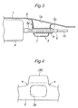
- Figure 3 is a fragmentary sectional side view taken along line III-III of Figure 2 to show how the pipe is arranged;
- Figure 4 is an illustrative view showing how cracks could develop when the
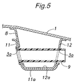
end plate 8 is not made of a separate piece; and - Figure 5 is an enlarged fragmentary view similar to Figure 3 showing another embodiment of the present invention.
- Figure 1 is a fragmentary perspective view of an
automotive floor panel 1 embodying the present invention. As shown in the drawing, thefloor panel 1 is made by stamp forming a relatively thin steel plate, and is provided with a plurality of beads (not shown in the drawings) so as to accommodate various components that are to be attached to thefloor panel 1 and to increase the bending rigidity of thefloor panel 1. - As shown in Figure 1, a laterally central part of the floor panel is formed with a
floor tunnel 2 extending in a fore-and-aft direction and having a trapezoidal cross section for the purpose ensuring a bending rigidity of the vehicle body around a lateral line. - The
floor panel 1 is also required to ensure an adequate bending rigidity of the vehicle body around a longitudinal line. To meet such a need, to alower surface 1a of thefloor panel 1 is attached across member 3 which extends laterally across the vehicle body and forms a closed cross section jointly with thelower surface 1a as best illustrated in Figure 2 showing thefloor panel 1 as seen from below. Thecross member 3 is provided with a U-shaped cross section as illustrated in Figure 3. Thecross member 3 thus defines a substantially rectangular closed cross section jointly with thefloor panel 1, and owing to this structural member defining a closed cross section extending across the width of thefloor panel 1, a required bending rigidity around a longitudinal line can be ensured. - In the floor structure of the illustrated embodiment, a
fuel tank 4 is installed on thelower surface 1a of thefloor panel 1 as illustrated in Figure 3. As shown in Figure 2, a pair offloor frames 5 each defining a closed cross section jointly with thefloor panel 1 are attached to thefloor panel 1 so as to extend along and adjacent to either side sill. The front end of eachfloor frame 5 is connected to a rear end of a corresponding side frame extending in an engine room not shown in the drawing and the rear end of eachfloor frame 5 is connected to thecross member 3. When thefuel tank 4 is installed between the twofloor frames 5, for instance, thefuel tank 4 can be secured in place by using a bracket or a band attached to thefloor frames 5 via threaded holes provided in appropriate parts of thefloor frames 5. - The
cross member 3 is provided in a central part along the longitudinal direction in view of balance, and thefuel tank 4 that occupies a relatively large volume is required to be placed so as not to interfere with thecross member 3. Also, the part of thefloor panel 1 receiving thefuel tank 4 inevitably bulges toward the passenger compartment particularly when thefloor panel 1 is given with a relatively low elevation. To circumvent this problem, thefuel tank 4 may be provided under the front seats. When the bulging part of thefloor panel 1 is located under the front seats, the part of the floor immediately in front of the rear seats is left unaffected, and the comfort of the legs of the vehicle occupants sitting in the rear seats would not be impaired. - When the
fuel tank 4 is disposed as described above, because the part of thefloor panel 1 directly under the front seats protrude into the passenger compartment, it is difficult to provide thecross member 3 in this region. Therefore, thecross member 3 is provided in the aforementioned location or a longitudinally central part on the under surface part of thefloor panel 1. This location may be located immediately ahead of the rear seats or, alternatively, immediately ahead of the front seats. This is also desirable for the purpose of keeping the elevation of the part of the floor corresponding to the legs of the rear seat occupants at a low level. When a filler pipe is provided in a rear part of the vehicle, the pipes (a fuel pipe and breather pipe) are required to be provided between thefuel tank 4 and filler pipe (not shown in the drawing) and extend across thecross member 3. To accommodate such pipes, the corresponding parts of thecross member 3 are formed withopenings 3a. Theseopenings 3a are formed in the mutually opposing walls of thecross member 3 having a U-shaped cross section so as to align with each other. - In the illustrated embodiment, as shown in Figure 3, the
cross member 3 consists of two pieces. The first piece consists of a main member 7 having a U-shaped cross section (first and second members), and the second piece consists of an end plate 8 (third member) which fills a recess defined by thefloor tunnel 2 as shown in Figure 2 also. When the main member 7 and theend plate 8 are formed as a single-piece plate member, there is a risk of developing cracks in the part indicated by arrows a in Figure 4 when stamp forming theopenings 3a in the mutually opposing walls of the main member 7. Therefore, in the case of the illustrated embodiment, the part of thecross member 3 shaped like a peninsula and extending from the main part of thecross member 3 is formed as a separate member so that cracks may not develop in the corresponding part when stamp forming theopenings 3a in the main member 7. The main member 7 andend plate 8 may be joined together by welding. - The piping work for the
fuel tank 4 can be accomplished by passing the pipe 6 through the twoopenings 3a. If theopenings 3a are left as they are, the pipe 6 may be passed easily through one of theopenings 3a, but there may be some difficulty in passing the pipe through the second opening 3a particularly when the distance between the twoopenings 3a is great. Therefore, atubular guide member 9 is fitted in the twoopenings 3a as illustrated in Figure 3. Theguide member 9 is made of plastic material, and is integrally molded with a radial flange at one end thereof for securing theguide member 9 in place. A part of theguide member 9 adjacent to the radial flange is provided with a resilient engagement piece formed with an engagement projection as a member cut out from the material of theguide member 9 so that the edge of thecorresponding opening 3a may be interposed between the engagement projection of the resilient engagement piece and the radial flange and theguide member 9 may be fixedly secured in thecross member 3. - Because the pipe 6 is guided by the
guide member 9 as it is passed through the space between the twoopenings 3a, the pipe 6 may be easily passed through both theopenings 3a. To permit thepipe 9 to be passed through theopenings 3a even when there are positional or dimensional errors, at least the part of the pipe 6 received by theopenings 3a may be made of rubber and formed as bellows. The part of the pipe 6 made of rubber and formed as bellows is passed through the twoopenings 3a (guide member 9), and is connected to ametallic pipe 10 extending in a rear part of the vehicle body behind thecross member 3. - According to the vehicle floor structure described above, because the
cross member 3 is not separated into two parts for passing a component part through thecross member 3, the bending rigidity of the floor panel would not be reduced. A reinforcing member that would be required if the cross member were separated into two parts would not be required, and a required mechanical strength can be ensured without requiring any such additional members. - When the
cross member 3 is provided with a peninsula-like part extending into the interior of thefloor tunnel 2 and formed as a separate member, the risk of developing cracks at the time of stamp forming theopenings 3a for receiving thepipe 9 can be avoided. Because thecross member 3 is provided with a closed cross section, there may be some difficulty in passing the pipe or the like through theopenings 3a formed in the opposing walls of thecross member 3, but placing theguide member 9 in theopenings 3a eliminates such a difficulty. - The
cross member 3 consisted of two pieces in the illustrated embodiment, by may also consist of three pieces as illustrated in Figure 5. In Figure 5, the parts corresponding to those of the previous embodiment are denoted with like numerals without repeating the description of such parts. - In the structure illustrated in Figure 5, the part corresponding to the main member 7 of the previous embodiment consists of a front member (first member) 11 and a rear member (second member) 12. The two
members bottom wall portions 11a and 11b which are laid over each other so as to define a bottom wall of thecross member 3 opposing thefloor panel 1. The twobottom wall portions 11a and 11b are welded to each other, and the two members are jointly formed into a shape similar to that of the main member 7 of the previous embodiment. Thereby, the process of stamp forming theopenings 3a can be simplified. - The component part which is passed through the
openings 3a of thecross member 3 consisted of a pipe 6 for afuel tank 4 in the illustrated embodiment, but may also consist of other component parts such as a wire harness, rod for transmitting torque to a part on the side of the rear wheels or the like. When such a component is passed through theopenings 3a of thecross member 3, there is no need to have a component part extend under thecross member 3, and the minimum height of the vehicle body is avoided from being reduced. Also, the bending rigidity of thecross member 3 would not be reduced. - The vehicle floor structure according to the present invention allows a component part to be passed through a cross member without reducing the bending rigidity of the cross member, and is therefore useful as a structure for passing a component part across a cross member.
- Although the present invention has been described in terms of preferred embodiments thereof, it is obvious to a person skilled in the art that various alterations and modifications are possible without departing from the scope of the present invention which is set forth in the appended claims.
- The contents of the original Japanese patent application on which the Paris Convention priority claim is made for the present application are incorporated in this application by reference.
Claims (7)
- A vehicle floor structure, comprising:a floor panel (1); anda cross member (3) extending laterally on a lower surface of the floor panel and including a front wall and a rear wall, the two walls being formed with openings (3a) that substantially align with each other.
- The vehicle floor structure according to claim 1, wherein the cross member defines a closed cross section jointly with the lower surface of the floor panel.
- The vehicle floor structure according to claim 1 or 2, wherein the cross member consists of a stamp formed single-piece plate member.
- The vehicle floor structure according to claim 1, 2 or 3, wherein the cross member includes a front member (11) and a rear member (12) that are joined to each other by respective bottom wall portions (11a, 12a) thereof.
- The vehicle floor structure according to any preceding claim, wherein the floor panel includes a floor tunnel (2) extending in a fore-and-aft direction, and the cross member includes an end plate (8) that fills a recess defined by the floor tunnel at a part thereof intersecting the cross member.
- The vehicle floor structure according to claim 5, wherein the end plate consists of a separate plate member which is attached to the cross member.
- The vehicle floor structure according to any preceding claim, further comprising a tubular guide member (9) for guiding a component part through the openings of the cross member that extends between the two openings.
Applications Claiming Priority (1)
| Application Number | Priority Date | Filing Date | Title |
|---|---|---|---|
| JP2005145178A JP4290143B2 (en) | 2005-05-18 | 2005-05-18 | Vehicle floor structure |
Publications (3)
| Publication Number | Publication Date |
|---|---|
| EP1724184A2 true EP1724184A2 (en) | 2006-11-22 |
| EP1724184A3 EP1724184A3 (en) | 2007-07-25 |
| EP1724184B1 EP1724184B1 (en) | 2009-03-11 |
Family
ID=36498702
Family Applications (1)
| Application Number | Title | Priority Date | Filing Date |
|---|---|---|---|
| EP20060251875 Ceased EP1724184B1 (en) | 2005-05-18 | 2006-04-03 | Vehicle floor structure |
Country Status (4)
| Country | Link |
|---|---|
| EP (1) | EP1724184B1 (en) |
| JP (1) | JP4290143B2 (en) |
| CN (1) | CN100465045C (en) |
| DE (1) | DE602006005541D1 (en) |
Cited By (3)
| Publication number | Priority date | Publication date | Assignee | Title |
|---|---|---|---|---|
| WO2008156000A1 (en) * | 2007-06-19 | 2008-12-24 | Honda Motor Co., Ltd. | Vehicle body floor structure |
| DE102015008262A1 (en) * | 2015-06-26 | 2016-12-29 | Audi Ag | Body assembly for a motor vehicle, motor vehicle and method of manufacturing a body assembly |
| US10414444B2 (en) | 2015-02-18 | 2019-09-17 | Honda Motor Co., Ltd. | Vehicle rear end structure |
Families Citing this family (5)
| Publication number | Priority date | Publication date | Assignee | Title |
|---|---|---|---|---|
| FR2962966B1 (en) * | 2010-07-23 | 2013-02-22 | Renault Sa | AUTOMOTIVE VEHICLE CHASSIS WITH BODY COMPONENTS AND ELECTRIC CABLES FIXED TO THE CENTRAL FLOOR |
| EP2628665B1 (en) * | 2010-10-13 | 2015-11-25 | Honda Motor Co., Ltd. | Vehicle body floor structure |
| KR101209998B1 (en) | 2011-06-14 | 2012-12-07 | 현대자동차주식회사 | Center floor panel assembly of vehicle |
| KR101210096B1 (en) | 2011-06-14 | 2012-12-07 | 현대자동차주식회사 | Center floor panel assembly of vehicle |
| WO2020241231A1 (en) * | 2019-05-28 | 2020-12-03 | 三菱自動車工業株式会社 | Vehicle body structure |
Citations (1)
| Publication number | Priority date | Publication date | Assignee | Title |
|---|---|---|---|---|
| JP2002302071A (en) | 2001-04-06 | 2002-10-15 | Honda Motor Co Ltd | Vehicle floor panel |
Family Cites Families (5)
| Publication number | Priority date | Publication date | Assignee | Title |
|---|---|---|---|---|
| JPH10226307A (en) * | 1997-02-13 | 1998-08-25 | Nissan Motor Co Ltd | Sensor mounting structure for side collision airbag device |
| FR2829457B1 (en) * | 2001-09-13 | 2004-12-03 | Peugeot Citroen Automobiles Sa | MOTOR VEHICLE CHASSIS |
| JP2003205870A (en) * | 2002-01-16 | 2003-07-22 | Nissan Motor Co Ltd | Automotive floor structure |
| DE10235532B4 (en) * | 2002-08-03 | 2005-03-24 | Daimlerchrysler Ag | Transverse bridge for the tunnel area of the floor structure of a motor vehicle body and tunnel area |
| US7104596B2 (en) * | 2003-10-16 | 2006-09-12 | Honda Motor Co., Ltd. | Vehicle body structure |
-
2005
- 2005-05-18 JP JP2005145178A patent/JP4290143B2/en not_active Expired - Fee Related
-
2006
- 2006-04-03 DE DE200660005541 patent/DE602006005541D1/en not_active Expired - Lifetime
- 2006-04-03 EP EP20060251875 patent/EP1724184B1/en not_active Ceased
- 2006-04-13 CN CNB2006100667985A patent/CN100465045C/en not_active Expired - Fee Related
Patent Citations (1)
| Publication number | Priority date | Publication date | Assignee | Title |
|---|---|---|---|---|
| JP2002302071A (en) | 2001-04-06 | 2002-10-15 | Honda Motor Co Ltd | Vehicle floor panel |
Cited By (5)
| Publication number | Priority date | Publication date | Assignee | Title |
|---|---|---|---|---|
| WO2008156000A1 (en) * | 2007-06-19 | 2008-12-24 | Honda Motor Co., Ltd. | Vehicle body floor structure |
| CN101674970B (en) * | 2007-06-19 | 2011-05-04 | 本田技研工业株式会社 | Vehicle body floor structure |
| US10414444B2 (en) | 2015-02-18 | 2019-09-17 | Honda Motor Co., Ltd. | Vehicle rear end structure |
| DE102015008262A1 (en) * | 2015-06-26 | 2016-12-29 | Audi Ag | Body assembly for a motor vehicle, motor vehicle and method of manufacturing a body assembly |
| DE102015008262B4 (en) * | 2015-06-26 | 2019-05-29 | Audi Ag | Body assembly for a motor vehicle, motor vehicle and method of manufacturing a body assembly |
Also Published As
| Publication number | Publication date |
|---|---|
| DE602006005541D1 (en) | 2009-04-23 |
| CN1865063A (en) | 2006-11-22 |
| EP1724184B1 (en) | 2009-03-11 |
| JP4290143B2 (en) | 2009-07-01 |
| JP2006321315A (en) | 2006-11-30 |
| CN100465045C (en) | 2009-03-04 |
| EP1724184A3 (en) | 2007-07-25 |
Similar Documents
| Publication | Publication Date | Title |
|---|---|---|
| EP3686091A1 (en) | Rear vehicle-body structure of vehicle, and vehicle | |
| US8282154B2 (en) | Vehicle body lateral side portion structure | |
| EP1808362B1 (en) | vehicle body | |
| CN210734286U (en) | Vehicle side structure | |
| US8075047B2 (en) | Automotive vehicle body structure | |
| EP1975042B1 (en) | Vehicle body structure | |
| US10150514B2 (en) | Vehicular body structure | |
| EP2639141A1 (en) | Structure for side portion of vehicle body | |
| CN107097858B (en) | Body structure | |
| EP2783951B1 (en) | Vehicle body superstructure | |
| JP7056303B2 (en) | Vehicle front body structure | |
| CN109249989B (en) | Steering support structure for vehicle | |
| JP7013995B2 (en) | Vehicle front body structure | |
| US20040080187A1 (en) | Body structure | |
| JP2000318653A (en) | Sill side part reinforcing structure for automobile | |
| US7380874B2 (en) | Automotive floor panel assembly | |
| JP4352769B2 (en) | Lower body structure of automobile | |
| EP1724184B1 (en) | Vehicle floor structure | |
| JP4853080B2 (en) | Auto body structure | |
| CN100577493C (en) | Automobile floor component | |
| US8042834B2 (en) | Front structure of vehicle | |
| CN107521565B (en) | Vehicle cowl reinforcing structure | |
| CN114450213A (en) | Floor structure of vehicle | |
| JPH11208520A (en) | Floor cross member reinforcing structure on car body of automobile | |
| JP2000177631A (en) | Car side body structure |
Legal Events
| Date | Code | Title | Description |
|---|---|---|---|
| PUAI | Public reference made under article 153(3) epc to a published international application that has entered the european phase |
Free format text: ORIGINAL CODE: 0009012 |
|
| AK | Designated contracting states |
Kind code of ref document: A2 Designated state(s): AT BE BG CH CY CZ DE DK EE ES FI FR GB GR HU IE IS IT LI LT LU LV MC NL PL PT RO SE SI SK TR |
|
| AX | Request for extension of the european patent |
Extension state: AL BA HR MK YU |
|
| PUAL | Search report despatched |
Free format text: ORIGINAL CODE: 0009013 |
|
| AK | Designated contracting states |
Kind code of ref document: A3 Designated state(s): AT BE BG CH CY CZ DE DK EE ES FI FR GB GR HU IE IS IT LI LT LU LV MC NL PL PT RO SE SI SK TR |
|
| AX | Request for extension of the european patent |
Extension state: AL BA HR MK YU |
|
| 17P | Request for examination filed |
Effective date: 20070907 |
|
| AKX | Designation fees paid |
Designated state(s): DE GB |
|
| GRAP | Despatch of communication of intention to grant a patent |
Free format text: ORIGINAL CODE: EPIDOSNIGR1 |
|
| GRAS | Grant fee paid |
Free format text: ORIGINAL CODE: EPIDOSNIGR3 |
|
| GRAA | (expected) grant |
Free format text: ORIGINAL CODE: 0009210 |
|
| AK | Designated contracting states |
Kind code of ref document: B1 Designated state(s): DE GB |
|
| REG | Reference to a national code |
Ref country code: GB Ref legal event code: FG4D |
|
| REF | Corresponds to: |
Ref document number: 602006005541 Country of ref document: DE Date of ref document: 20090423 Kind code of ref document: P |
|
| PLBE | No opposition filed within time limit |
Free format text: ORIGINAL CODE: 0009261 |
|
| STAA | Information on the status of an ep patent application or granted ep patent |
Free format text: STATUS: NO OPPOSITION FILED WITHIN TIME LIMIT |
|
| 26N | No opposition filed |
Effective date: 20091214 |
|
| REG | Reference to a national code |
Ref country code: DE Ref legal event code: R084 Ref document number: 602006005541 Country of ref document: DE |
|
| REG | Reference to a national code |
Ref country code: GB Ref legal event code: 746 Effective date: 20150217 |
|
| REG | Reference to a national code |
Ref country code: DE Ref legal event code: R084 Ref document number: 602006005541 Country of ref document: DE Effective date: 20150210 |
|
| PGFP | Annual fee paid to national office [announced via postgrant information from national office to epo] |
Ref country code: GB Payment date: 20170329 Year of fee payment: 12 |
|
| PGFP | Annual fee paid to national office [announced via postgrant information from national office to epo] |
Ref country code: DE Payment date: 20180320 Year of fee payment: 13 |
|
| GBPC | Gb: european patent ceased through non-payment of renewal fee |
Effective date: 20180403 |
|
| PG25 | Lapsed in a contracting state [announced via postgrant information from national office to epo] |
Ref country code: GB Free format text: LAPSE BECAUSE OF NON-PAYMENT OF DUE FEES Effective date: 20180403 |
|
| REG | Reference to a national code |
Ref country code: DE Ref legal event code: R119 Ref document number: 602006005541 Country of ref document: DE |
|
| PG25 | Lapsed in a contracting state [announced via postgrant information from national office to epo] |
Ref country code: DE Free format text: LAPSE BECAUSE OF NON-PAYMENT OF DUE FEES Effective date: 20191101 |