EP1724152A1 - Signal assembly - Google Patents
Signal assembly Download PDFInfo
- Publication number
- EP1724152A1 EP1724152A1 EP05010704A EP05010704A EP1724152A1 EP 1724152 A1 EP1724152 A1 EP 1724152A1 EP 05010704 A EP05010704 A EP 05010704A EP 05010704 A EP05010704 A EP 05010704A EP 1724152 A1 EP1724152 A1 EP 1724152A1
- Authority
- EP
- European Patent Office
- Prior art keywords
- ring
- light
- assembly
- flange
- light stick
- Prior art date
- Legal status (The legal status is an assumption and is not a legal conclusion. Google has not performed a legal analysis and makes no representation as to the accuracy of the status listed.)
- Granted
Links
Images






Classifications
-
- B—PERFORMING OPERATIONS; TRANSPORTING
- B60—VEHICLES IN GENERAL
- B60Q—ARRANGEMENT OF SIGNALLING OR LIGHTING DEVICES, THE MOUNTING OR SUPPORTING THEREOF OR CIRCUITS THEREFOR, FOR VEHICLES IN GENERAL
- B60Q7/00—Arrangement or adaptation of portable emergency signal devices on vehicles
-
- E—FIXED CONSTRUCTIONS
- E01—CONSTRUCTION OF ROADS, RAILWAYS, OR BRIDGES
- E01F—ADDITIONAL WORK, SUCH AS EQUIPPING ROADS OR THE CONSTRUCTION OF PLATFORMS, HELICOPTER LANDING STAGES, SIGNS, SNOW FENCES, OR THE LIKE
- E01F9/00—Arrangement of road signs or traffic signals; Arrangements for enforcing caution
- E01F9/60—Upright bodies, e.g. marker posts or bollards; Supports for road signs
- E01F9/604—Upright bodies, e.g. marker posts or bollards; Supports for road signs specially adapted for particular signalling purposes, e.g. for indicating curves, road works or pedestrian crossings
- E01F9/615—Upright bodies, e.g. marker posts or bollards; Supports for road signs specially adapted for particular signalling purposes, e.g. for indicating curves, road works or pedestrian crossings illuminated
-
- E—FIXED CONSTRUCTIONS
- E01—CONSTRUCTION OF ROADS, RAILWAYS, OR BRIDGES
- E01F—ADDITIONAL WORK, SUCH AS EQUIPPING ROADS OR THE CONSTRUCTION OF PLATFORMS, HELICOPTER LANDING STAGES, SIGNS, SNOW FENCES, OR THE LIKE
- E01F9/00—Arrangement of road signs or traffic signals; Arrangements for enforcing caution
- E01F9/60—Upright bodies, e.g. marker posts or bollards; Supports for road signs
- E01F9/688—Free-standing bodies
Definitions
- the present invention relates to a signal assembly wherein the light stick can be separated from the legs and held by the users.
- a conventional signal assembly is disclosed in Figs. 7-9, and generally includes a tube 50 which includes battery section 52 and a light bulb section 51, a sleeve 71 is slidably mounted to the tube 50 and three leg plates 70 are pivotably connected to the sleeve 71, three extension rods 72 are pivotably connected between the tube 50 and the three leg plates 70, and a light device 60 is pivotably connected between two lugs of a frame 54 which is connected to a base 53 which is connected to a top of the tube 50.
- Two conductive members 55 are connected to the two lugs of the frame 54 and the light device 60 is electrically connected to the conductive member 55 by two conductive pins 61.
- the three leg plates 70 can be pivoted and cooperated with a transverse plate 73 to form a warning triangular frame as shown in Fig. 9 and the light device 60 provide illumination.
- the conventional signal assembly is mainly focused on a stationary waning purpose and is too big to be held by the users when needed.
- the present invention intends to provide a signal assembly which includes a light stick that can be separated from the leg plates and can be held by the users conveniently.
- the present invention relates to a signal assembly which comprises a light device connected to a light stick and three connection hooks extend from an outer periphery of the light stick.
- a first connection assembly is mounted to the light stick and includes a first ring and a second ring which is mounted to the first ring.
- the first ring has a first flange extending outward from a first end thereof and three notches are defined through the first flange.
- the second ring has three openings defined in a lower end thereof.
- the connection hooks are engaged with the three notches and hooked with the first flange by rotating the light stick relative to the first ring.
- Three leg plates each have a first end pivotably engaged with the three openings in the second ring.
- a second connection assembly is slidably mounted to the light stick and three stretch rods are pivotably connected between the three leg plates and the second connection assembly.
- the signal assembly "A" of the present invention comprises a light device 10 that is a tubular member with two light bulbs 11 on two ends thereof and a connection neck 12 extends from a mediate portion of the light device 10.
- a light stick 20 is a transparent or semi-transparent tube 21 and has a threaded portion 211 on a first end thereof so that the connection neck 12 is threadedly connected with the threaded portion 211 of the light stick 20.
- a battery pack 23 and a light bulb 25 are received in an interior 22 of the light stick 20.
- a control circuit board 24 is electrically connected to the battery pack 23 and a light bulb 25.
- the other end of the battery pack 23 is connected to a conductive plate 13 in the connection neck 12 and the two light bulbs 11 are electrically connected to the conductive plate 13.
- a switch assembly 26 is electrically connected to the control circuit board 24 and exposed from the outer periphery of the light stick 20 so that the user may optionally operate the light device 10 and/or the light bulb 25 in the light stick 20.
- Three connection hooks 27 extend from an outer periphery of the light stick 20.
- a first connection assembly 30 is mounted to the light stick 20 and includes a first ring 31 and a second ring 32.
- the first ring 31 has a first flange 311 extending outward from a first end thereof and three notches 312 are defined through the first flange 311.
- a plurality of slits 313 are defined in the first ring 31 so as to form a plurality of flexible studs separated by the slits 313 such that the first ring 31 can be squeezed into a central hole of the second ring 32.
- a second flange 315 extends outward from a second end of the first ring 31.
- the second ring 32 has three openings 321 defined in a lower end thereof.
- the light stick 20 extends through the first and second rings 31, 32 and the connection hooks 27 are engaged with the three notches 312 and hooked with the first flange 311 by rotating the light stick 20 relative to the first ring 31.
- the light stick 21 is able to separated from the first connection assembly 30 by operating the light stick 20 in reverse direction.
- Three leg plates 40 each are an elongate and curve plate and have a protrusion 42 extending from an inside of a first end of each of the three leg plates 40 and the three protrusions 42 are engaged with the three openings 321 of the second ring 32.
- the second flange 315 extending outward from the second end of the first ring 31 supports and restricts the protrusion 42 within the opening 321.
- a second connection assembly 300 mounted to a groove 28 defined in the outer periphery of a second end of the light stick 20, and includes a third ring 33 and a fourth ring 34 which is identical with the second ring 32 and is arranged to be up-side-down to let the openings face the third ring 33.
- the third ring 33 has a plurality of engaging bosses 336 extending from an inner periphery thereof and the engaging bosses 336 are engaged with the groove 28 of the light stick 20.
- Three stretch rods 45 are pivotably connected between three connection studs 43 in the inner side of the three leg plates 40 and the second connection assembly 300.
- the third ring 33 includes a third flange 331 extending from a first end thereof and three notches 332 are defined in the third flange 331 so as to receive the stretch rods 45 when the leg plates 40 are not opened.
- a fourth flange 335 extends outward from a second end of the third ring 33. The third ring 33 is engaged with a central hole of the fourth ring 34 and three respective ends of the three stretch rods 45 are respectively engaged with the openings in the fourth ring 34 and restricted by the fourth flange 335.
- the three leg plates 31 can be pivoted outward about the first connection assembly 30 and the three stretch rods 45 are pivoted outward to provide a stable structure.
- a transverse plate 46 can be fixed between any two adjacent leg plates 40 by proper connection members which connect the two ends of the transverse plate 46 to the two connection holes 44 in the leg plates 40.
- the transverse plate 46 and the two leg plates 40 forms a triangular warning sign.
- the light stick 20 can be easily separated from the first and second connection assemblies 30, 300 and the leg plates 40 by rotating it relative to the first ring 31 and removing the connection hooks 27 from the notches 312.
- the light stick 20 can be easily held by the users.
Landscapes
- Engineering & Computer Science (AREA)
- Architecture (AREA)
- Civil Engineering (AREA)
- Structural Engineering (AREA)
- Mechanical Engineering (AREA)
- Arrangement Of Elements, Cooling, Sealing, Or The Like Of Lighting Devices (AREA)
Abstract
Description
- The present invention relates to a signal assembly wherein the light stick can be separated from the legs and held by the users.
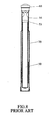
- A conventional signal assembly is disclosed in Figs. 7-9, and generally includes a
tube 50 which includesbattery section 52 and alight bulb section 51, asleeve 71 is slidably mounted to thetube 50 and threeleg plates 70 are pivotably connected to thesleeve 71, threeextension rods 72 are pivotably connected between thetube 50 and the threeleg plates 70, and alight device 60 is pivotably connected between two lugs of aframe 54 which is connected to abase 53 which is connected to a top of thetube 50. Twoconductive members 55 are connected to the two lugs of theframe 54 and thelight device 60 is electrically connected to theconductive member 55 by twoconductive pins 61. The threeleg plates 70 can be pivoted and cooperated with atransverse plate 73 to form a warning triangular frame as shown in Fig. 9 and thelight device 60 provide illumination. The conventional signal assembly is mainly focused on a stationary waning purpose and is too big to be held by the users when needed. - The present invention intends to provide a signal assembly which includes a light stick that can be separated from the leg plates and can be held by the users conveniently.
- The present invention relates to a signal assembly which comprises a light device connected to a light stick and three connection hooks extend from an outer periphery of the light stick. A first connection assembly is mounted to the light stick and includes a first ring and a second ring which is mounted to the first ring. The first ring has a first flange extending outward from a first end thereof and three notches are defined through the first flange. The second ring has three openings defined in a lower end thereof. The connection hooks are engaged with the three notches and hooked with the first flange by rotating the light stick relative to the first ring. Three leg plates each have a first end pivotably engaged with the three openings in the second ring. A second connection assembly is slidably mounted to the light stick and three stretch rods are pivotably connected between the three leg plates and the second connection assembly.
- The present invention will become more obvious from the following description when taken in connection with the accompanying drawings which show, for purposes of illustration only, a preferred embodiment in accordance with the present invention.
-
- Fig. 1 is a perspective view to show the signal assembly of the present invention;
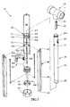
- Fig. 2 is an exploded view to show the signal assembly of the present invention;
- Fig. 3 is a cross sectional view to show the signal assembly of the present invention;
- Fig. 4 is a cross sectional view to show the signal assembly of the present invention, wherein the leg plates are opened wide;
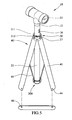
- Fig. 5 is a perspective view to show the signal assembly of the present invention with the leg plates opened wide;
- Fig. 6 shows that the light stick is independently used;
- Fig. 7 is an exploded view to show a conventional signal assembly;
- Fig. 8 is a cross sectional view of the conventional signal assembly, and
- Fig. 9 shows that the leg plates of the conventional signal assembly are opened wide.
- Referring to Figs. 1 to 3, the signal assembly "A" of the present invention comprises a
light device 10 that is a tubular member with twolight bulbs 11 on two ends thereof and aconnection neck 12 extends from a mediate portion of thelight device 10. Alight stick 20 is a transparent orsemi-transparent tube 21 and has a threadedportion 211 on a first end thereof so that theconnection neck 12 is threadedly connected with the threadedportion 211 of thelight stick 20. Abattery pack 23 and alight bulb 25 are received in aninterior 22 of thelight stick 20. Acontrol circuit board 24 is electrically connected to thebattery pack 23 and alight bulb 25. The other end of thebattery pack 23 is connected to aconductive plate 13 in theconnection neck 12 and the twolight bulbs 11 are electrically connected to theconductive plate 13. Aswitch assembly 26 is electrically connected to thecontrol circuit board 24 and exposed from the outer periphery of thelight stick 20 so that the user may optionally operate thelight device 10 and/or thelight bulb 25 in thelight stick 20. Threeconnection hooks 27 extend from an outer periphery of thelight stick 20. - A
first connection assembly 30 is mounted to thelight stick 20 and includes afirst ring 31 and asecond ring 32. Thefirst ring 31 has afirst flange 311 extending outward from a first end thereof and threenotches 312 are defined through thefirst flange 311. A plurality ofslits 313 are defined in thefirst ring 31 so as to form a plurality of flexible studs separated by theslits 313 such that thefirst ring 31 can be squeezed into a central hole of thesecond ring 32. Asecond flange 315 extends outward from a second end of thefirst ring 31. - The
second ring 32 has threeopenings 321 defined in a lower end thereof. Thelight stick 20 extends through the first andsecond rings connection hooks 27 are engaged with the threenotches 312 and hooked with thefirst flange 311 by rotating thelight stick 20 relative to thefirst ring 31. In other words, thelight stick 21 is able to separated from thefirst connection assembly 30 by operating thelight stick 20 in reverse direction. - Three
leg plates 40 each are an elongate and curve plate and have aprotrusion 42 extending from an inside of a first end of each of the threeleg plates 40 and the threeprotrusions 42 are engaged with the threeopenings 321 of thesecond ring 32. Thesecond flange 315 extending outward from the second end of thefirst ring 31 supports and restricts theprotrusion 42 within the opening 321. - A
second connection assembly 300 mounted to agroove 28 defined in the outer periphery of a second end of thelight stick 20, and includes athird ring 33 and afourth ring 34 which is identical with thesecond ring 32 and is arranged to be up-side-down to let the openings face thethird ring 33. Thethird ring 33 has a plurality ofengaging bosses 336 extending from an inner periphery thereof and theengaging bosses 336 are engaged with thegroove 28 of thelight stick 20. Threestretch rods 45 are pivotably connected between threeconnection studs 43 in the inner side of the threeleg plates 40 and thesecond connection assembly 300. Thethird ring 33 includes a third flange 331 extending from a first end thereof and threenotches 332 are defined in the third flange 331 so as to receive thestretch rods 45 when theleg plates 40 are not opened. Afourth flange 335 extends outward from a second end of thethird ring 33. Thethird ring 33 is engaged with a central hole of thefourth ring 34 and three respective ends of the threestretch rods 45 are respectively engaged with the openings in thefourth ring 34 and restricted by thefourth flange 335. - As shown in Figs. 4 and 5, the three
leg plates 31 can be pivoted outward about thefirst connection assembly 30 and the threestretch rods 45 are pivoted outward to provide a stable structure. Atransverse plate 46 can be fixed between any twoadjacent leg plates 40 by proper connection members which connect the two ends of thetransverse plate 46 to the twoconnection holes 44 in theleg plates 40. Thetransverse plate 46 and the twoleg plates 40 forms a triangular warning sign. - As shown in Fig. 6, the
light stick 20 can be easily separated from the first and second connection assemblies 30, 300 and theleg plates 40 by rotating it relative to thefirst ring 31 and removing theconnection hooks 27 from thenotches 312. Thelight stick 20 can be easily held by the users. - While we have shown and described the embodiment in accordance with the present invention, it should be clear to those skilled in the art that further embodiments may be made without departing from the scope of the present invention.
Claims (7)
- A signal assembly comprising:a light device;a light stick having a first end connected to the light device and three connection hooks extending from an outer periphery of the light stick;a first connection assembly mounted to the light stick and including a first ring and a second ring, the first ring having a first flange extending outward from a first end thereof and three notches defined through the first flange, the second ring having three openings defined in a lower end thereof, the first ring inserted in a central hole of the second ring, the connection hooks removably engaged with the three notches and hooked with the first flange by rotating the light stick relative to the first ring;three leg plates each having a first end pivotably engaged with the three openings in the second ring, anda second connection assembly mounted to the light stick and three stretch rods pivotably connected between the three leg plates and the second connection assembly.
- The assembly as claimed in claim 1, wherein a protrusion extends from an inside of the first end of each of the three leg plates and the three protrusions are engaged with the three openings of the second ring, a second flange extends outward from a second end of the first ring and supports and restricts the protrusion within the opening.
- The assembly as claimed in claim 1, wherein a plurality of slits defined in the first ring so as to form a plurality of flexible studs separated by the slits.
- The assembly as claimed in claim 1, wherein a battery pack and a light bulb are received in an interior of the light stick, a control circuit board is electrically connected to the battery pack and a light bulb, a switch assembly is electrically connected to the control circuit board and exposed from the outer periphery of the light stick.
- The assembly as claimed in claim 1, wherein the light device includes two light bulbs on two ends thereof and a connection neck extends from a mediate portion of the light device, the light stick has a threaded portion on the first end thereof so that the connection neck is threadedly connected with the threaded portion of the light stick.
- The assembly as claimed in claim 1, wherein the second connection assembly includes a third ring and a fourth ring, the third ring includes a third flange extending from a first end thereof and three notches are defined in the third flange so as to receive the stretch rods when the leg plates are not opened, a fourth flange extends outward from a second end of the third ring, the fourth ring includes three openings which face the third ring, the third ring engaged with a central hole of the fourth ring and three respective ends of the three stretch rods are respectively engaged with the openings in the fourth ring and restricted by the fourth flange.
- The assembly as claimed in claim 6, wherein the third ring has a plurality of engaging bosses extending from an inner periphery thereof and the engaging bosses are engaged with a groove defined in the outer periphery of a second end of the light stick.
Priority Applications (2)
| Application Number | Priority Date | Filing Date | Title |
|---|---|---|---|
| DE602005008720T DE602005008720D1 (en) | 2005-05-18 | 2005-05-18 | signal arrangement |
| EP05010704A EP1724152B1 (en) | 2005-05-18 | 2005-05-18 | Signal assembly |
Applications Claiming Priority (1)
| Application Number | Priority Date | Filing Date | Title |
|---|---|---|---|
| EP05010704A EP1724152B1 (en) | 2005-05-18 | 2005-05-18 | Signal assembly |
Publications (2)
| Publication Number | Publication Date |
|---|---|
| EP1724152A1 true EP1724152A1 (en) | 2006-11-22 |
| EP1724152B1 EP1724152B1 (en) | 2008-08-06 |
Family
ID=35735325
Family Applications (1)
| Application Number | Title | Priority Date | Filing Date |
|---|---|---|---|
| EP05010704A Expired - Lifetime EP1724152B1 (en) | 2005-05-18 | 2005-05-18 | Signal assembly |
Country Status (2)
| Country | Link |
|---|---|
| EP (1) | EP1724152B1 (en) |
| DE (1) | DE602005008720D1 (en) |
Citations (3)
| Publication number | Priority date | Publication date | Assignee | Title |
|---|---|---|---|---|
| US20040124997A1 (en) * | 2002-12-31 | 2004-07-01 | Wu-Lung Chu | Luminous alarm device |
| US20040140911A1 (en) * | 2003-01-17 | 2004-07-22 | Jen-Fu Chen | Warning device |
| DE202004010953U1 (en) * | 2004-07-13 | 2004-10-14 | Chen, Hsiu Chin | Multiple function warning unit for car breakdown has lamp mounting base containing rechargeable battery unit and connector for car electrical socket |
-
2005
- 2005-05-18 DE DE602005008720T patent/DE602005008720D1/en not_active Expired - Fee Related
- 2005-05-18 EP EP05010704A patent/EP1724152B1/en not_active Expired - Lifetime
Patent Citations (3)
| Publication number | Priority date | Publication date | Assignee | Title |
|---|---|---|---|---|
| US20040124997A1 (en) * | 2002-12-31 | 2004-07-01 | Wu-Lung Chu | Luminous alarm device |
| US20040140911A1 (en) * | 2003-01-17 | 2004-07-22 | Jen-Fu Chen | Warning device |
| DE202004010953U1 (en) * | 2004-07-13 | 2004-10-14 | Chen, Hsiu Chin | Multiple function warning unit for car breakdown has lamp mounting base containing rechargeable battery unit and connector for car electrical socket |
Also Published As
| Publication number | Publication date |
|---|---|
| DE602005008720D1 (en) | 2008-09-18 |
| EP1724152B1 (en) | 2008-08-06 |
Similar Documents
| Publication | Publication Date | Title |
|---|---|---|
| US7224271B2 (en) | Signal assembly | |
| US20050276045A1 (en) | LED utility light | |
| US6511203B1 (en) | Beacon light | |
| US9625106B2 (en) | LED conversion module for incandescent work light | |
| US10161602B1 (en) | Illuminating device | |
| EP2615357A2 (en) | LED light tube assembly with replaceable circuit board | |
| US3015720A (en) | Portable telescopic outdoor electric lantern | |
| US6158871A (en) | Illuminating ball-point pen | |
| US7140746B2 (en) | Multipurpose illumination device | |
| EP1724152B1 (en) | Signal assembly | |
| US4731716A (en) | Collapsible lamp-shade structure | |
| JP3171199U (en) | Lamp stand structure of serial connection type lighting tube | |
| US20110136370A1 (en) | Connecting structure of a lamp head base and a lamp tube base | |
| KR200395978Y1 (en) | Signal assembly | |
| US20080010879A1 (en) | Commercial sign | |
| TWI467113B (en) | Fluorescent tube | |
| KR200396966Y1 (en) | The height lamp | |
| US9927089B1 (en) | Lampshade | |
| KR200303512Y1 (en) | Bulb socket structure | |
| CN213712731U (en) | Lamp holder | |
| US3283137A (en) | Flashlight | |
| CN216562858U (en) | Electronic equipment | |
| CN213040343U (en) | Detachable lamp shell and lantern | |
| CN210091950U (en) | Switch with indication function | |
| US20020176256A1 (en) | Lighting fixture |
Legal Events
| Date | Code | Title | Description |
|---|---|---|---|
| PUAI | Public reference made under article 153(3) epc to a published international application that has entered the european phase |
Free format text: ORIGINAL CODE: 0009012 |
|
| AK | Designated contracting states |
Kind code of ref document: A1 Designated state(s): AT BE BG CH CY CZ DE DK EE ES FI FR GB GR HU IE IS IT LI LT LU MC NL PL PT RO SE SI SK TR |
|
| AX | Request for extension of the european patent |
Extension state: AL BA HR LV MK YU |
|
| 17P | Request for examination filed |
Effective date: 20070529 |
|
| AKX | Designation fees paid |
Designated state(s): DE FR GB IT SE |
|
| 17Q | First examination report despatched |
Effective date: 20070629 |
|
| GRAP | Despatch of communication of intention to grant a patent |
Free format text: ORIGINAL CODE: EPIDOSNIGR1 |
|
| GRAS | Grant fee paid |
Free format text: ORIGINAL CODE: EPIDOSNIGR3 |
|
| GRAA | (expected) grant |
Free format text: ORIGINAL CODE: 0009210 |
|
| AK | Designated contracting states |
Kind code of ref document: B1 Designated state(s): DE FR GB IT SE |
|
| REG | Reference to a national code |
Ref country code: GB Ref legal event code: FG4D |
|
| REF | Corresponds to: |
Ref document number: 602005008720 Country of ref document: DE Date of ref document: 20080918 Kind code of ref document: P |
|
| PLBE | No opposition filed within time limit |
Free format text: ORIGINAL CODE: 0009261 |
|
| STAA | Information on the status of an ep patent application or granted ep patent |
Free format text: STATUS: NO OPPOSITION FILED WITHIN TIME LIMIT |
|
| 26N | No opposition filed |
Effective date: 20090507 |
|
| PG25 | Lapsed in a contracting state [announced via postgrant information from national office to epo] |
Ref country code: IT Free format text: LAPSE BECAUSE OF FAILURE TO SUBMIT A TRANSLATION OF THE DESCRIPTION OR TO PAY THE FEE WITHIN THE PRESCRIBED TIME-LIMIT Effective date: 20080806 |
|
| GBPC | Gb: european patent ceased through non-payment of renewal fee |
Effective date: 20090518 |
|
| PG25 | Lapsed in a contracting state [announced via postgrant information from national office to epo] |
Ref country code: SE Free format text: LAPSE BECAUSE OF FAILURE TO SUBMIT A TRANSLATION OF THE DESCRIPTION OR TO PAY THE FEE WITHIN THE PRESCRIBED TIME-LIMIT Effective date: 20081106 |
|
| REG | Reference to a national code |
Ref country code: FR Ref legal event code: ST Effective date: 20100129 |
|
| PG25 | Lapsed in a contracting state [announced via postgrant information from national office to epo] |
Ref country code: FR Free format text: LAPSE BECAUSE OF NON-PAYMENT OF DUE FEES Effective date: 20090602 |
|
| PG25 | Lapsed in a contracting state [announced via postgrant information from national office to epo] |
Ref country code: GB Free format text: LAPSE BECAUSE OF NON-PAYMENT OF DUE FEES Effective date: 20090518 |
|
| PG25 | Lapsed in a contracting state [announced via postgrant information from national office to epo] |
Ref country code: DE Free format text: LAPSE BECAUSE OF NON-PAYMENT OF DUE FEES Effective date: 20091201 |