EP1722680B1 - Distributed cardiac activity monitoring with selective filtering - Google Patents
Distributed cardiac activity monitoring with selective filtering Download PDFInfo
- Publication number
- EP1722680B1 EP1722680B1 EP05713679.8A EP05713679A EP1722680B1 EP 1722680 B1 EP1722680 B1 EP 1722680B1 EP 05713679 A EP05713679 A EP 05713679A EP 1722680 B1 EP1722680 B1 EP 1722680B1
- Authority
- EP
- European Patent Office
- Prior art keywords
- wave
- filter
- monitoring
- signal
- abnormal
- Prior art date
- Legal status (The legal status is an assumption and is not a legal conclusion. Google has not performed a legal analysis and makes no representation as to the accuracy of the status listed.)
- Expired - Lifetime
Links
Images



Classifications
-
- A—HUMAN NECESSITIES
- A61—MEDICAL OR VETERINARY SCIENCE; HYGIENE
- A61B—DIAGNOSIS; SURGERY; IDENTIFICATION
- A61B5/00—Measuring for diagnostic purposes; Identification of persons
- A61B5/0002—Remote monitoring of patients using telemetry, e.g. transmission of vital signals via a communication network
- A61B5/0004—Remote monitoring of patients using telemetry, e.g. transmission of vital signals via a communication network characterised by the type of physiological signal transmitted
- A61B5/0006—ECG or EEG signals
-
- A—HUMAN NECESSITIES
- A61—MEDICAL OR VETERINARY SCIENCE; HYGIENE
- A61B—DIAGNOSIS; SURGERY; IDENTIFICATION
- A61B5/00—Measuring for diagnostic purposes; Identification of persons
- A61B5/24—Detecting, measuring or recording bioelectric or biomagnetic signals of the body or parts thereof
- A61B5/316—Modalities, i.e. specific diagnostic methods
- A61B5/318—Heart-related electrical modalities, e.g. electrocardiography [ECG]
- A61B5/346—Analysis of electrocardiograms
- A61B5/349—Detecting specific parameters of the electrocardiograph cycle
- A61B5/355—Detecting T-waves
-
- Y—GENERAL TAGGING OF NEW TECHNOLOGICAL DEVELOPMENTS; GENERAL TAGGING OF CROSS-SECTIONAL TECHNOLOGIES SPANNING OVER SEVERAL SECTIONS OF THE IPC; TECHNICAL SUBJECTS COVERED BY FORMER USPC CROSS-REFERENCE ART COLLECTIONS [XRACs] AND DIGESTS
- Y10—TECHNICAL SUBJECTS COVERED BY FORMER USPC
- Y10S—TECHNICAL SUBJECTS COVERED BY FORMER USPC CROSS-REFERENCE ART COLLECTIONS [XRACs] AND DIGESTS
- Y10S128/00—Surgery
- Y10S128/901—Suppression of noise in electric signal
Definitions
- the present application describes systems and techniques relating to monitoring cardiac activity, for example, processing cardiac electrical activity to determine heart rate.
- the electrical activity of the heart can be monitored to track various aspects of the functioning of the heart. Given the volume conductivity of the body, electrodes on the body surface or beneath the skin can display potential differences related to this activity. Anomalous electrical activity can be indicative of disease states or other physiological conditions ranging from benign to fatal.
- Cardiac monitoring devices can sense the cardiac electrical activity of a living being and identify heart beats. Frequently, identification of heart beats is performed by identifying the R waves in the QRS complex, as can be seen in an electrocardiogram (ECG).
- ECG electrocardiogram
- the R wave is the first positive deflection in the QRS complex, representing ventricular depolarization. The typically large amplitude of this positive deflection in the QRS complex is useful in identifying a heart beat.
- US 3,593,705 describes a monitoring apparatus and method for determining the presence of cardiac arrhythmias by means of pattern recognition techniques. In one embodiment, the arrangement rejects a QRS complex based on a measure of the T-wave.
- US 4,240,442 describes an R wave detector for use in monitoring and/or analyzing electrical heart waveforms. A variable threshold is provided which enables increased sensitivity to small amplitude R waves without requiring the threshold to remain so low as to additionally detect the subsequent T waves.
- US 2003/204215 describes a method and apparatus for automatically identifying various types of cardiac and non-cardiac over sensing. In one arrangement, if T wave over sensing is detected, the ventricular sensitivity can be reprogrammed.
- US 4,887,609 describes an electro cardiograph filtering apparatus and method in which an ECG signal is filtered to remove unwanted signals, such as contamination signals produced by the use of a nuclear magnetic resonance imaging system or muscle artefact signals.
- US 6,167,258 describes a programmable wireless data acquisition system and describes various kinds of filters, including a prefilter to reject inputs that are outside of a frequency band of interest, an AC coupling high pass filter to reject the DC offset or steady state value of an external input, an anti-alias low pass filter to guard against false signals caused by aliasing between the external input content and the sampling rate of downstream sampling functions, and a digital filter to reject certain portions of the digital data stream to provide an effective decrease in resolution.
- FIG. 1 illustrates a distributed cardiac activity monitoring system in which a cardiac signal is monitored for medical purposes.
- FIG. 2 illustrates an example cardiac monitoring apparatus used with a living being.
- FIG. 3 illustrates an example ECG of a normal patient.
- FIG. 4 illustrates an example ECG of a patient with abnormal T waves.
- FIG. 5 illustrates a process of selectively activating a T wave filter.
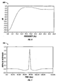
- FIG. 6 illustrates a frequency response of an example T wave filter.
- FIG. 7 illustrates an impulse response of an example T wave filter.
- FIG. 8 illustrates an example distributed process for selectively activating a T wave filter.
- FIG. 1 illustrates a distributed cardiac activity monitoring system 100 in which a cardiac signal is monitored for medical purposes.
- a living being 110 e.g., a human patient, including potentially a healthy patient for whom cardiac monitoring is nonetheless deemed appropriate
- the cardiac monitoring apparatus 120 can be composed of one or more devices, such as a sensing device 122 and a processing device 124.
- the cardiac monitoring apparatus 120 can communicate with a monitoring station 140 (e.g., a computer in a monitoring center) via a communications channel 130.
- a monitoring station 140 e.g., a computer in a monitoring center
- the cardiac monitoring apparatus 120 can include one or more sensing, calibration, signal processing, control, data storage, and transmission elements suitable for generating and processing the cardiac signal, as well as for relaying all or a portion of the cardiac signal over the communications channel 130.
- the communications channel 130 can be part of a communications network and can include any suitable medium for data transmission, including wired and wireless media suitable for carrying optical and/or electrical signals.
- the cardiac monitoring apparatus 120 can communicate sensed cardiac signals (e.g,, ECG data), cardiac event information (e.g., real-time heart rate data), and additional physiological and/or other information to the monitoring station 140.
- the cardiac monitoring apparatus 120 can include an implantable medical device, such as an implantable cardiac defibrillator and an associated transceiver or pacemaker and an associated transceiver, or an external monitoring device that the patient wears.
- the cardiac monitoring apparatus 120 can be implemented using, for example, the CardioNet Mobile Cardiac Outpatient Telemetry (MCOT) device, which is commercially available and provided by CardioNet, Inc of San Diego, CA.
- MCOT CardioNet Mobile Cardiac Outpatient Telemetry
- the monitoring station 140 can include a receiver element for receiving transmitted signals, as well as various data processing and storage elements for extracting and storing information carried by transmissions regarding the state of the individual 110.
- the monitoring station 140 can be located in the same general location (e.g., in the same room, building or health care facility) as the monitoring apparatus 120, or at a remote location.
- the monitoring station 140 can include a display and a processing system, and a system operator 150 (e.g., a doctor or a cardiovascular technician) can use the monitoring station 140 to evaluate physiological data received from the cardiac monitoring apparatus 120.
- the system operator 150 can use the monitoring station 140 to change operational settings of the cardiac monitoring apparatus 120 remotely during active cardiac monitoring of the living being 110.
- the cardiac monitoring apparatus 120 can selectively activate a T wave filter in response to discovery of a predetermined characteristic in the sensed cardiac signal, such as described further below. For example, the system operator can determine that the patient has consistently abnormal T waves and cause the monitoring station 140 to send a message to the monitoring apparatus 120 to activate the T wave filter.
- FIG. 2 illustrates an example cardiac monitoring apparatus 200 used with a living being.
- the apparatus 200 can include a sensor 210, a signal amplifier 220, a T wave filter 230, a selector 240, a beat detector 250, additional logic 260, and a communications interface 270.
- the sensor 210 can include two or more electrodes subject to one or more potential differences that yield a voltage signal, such as the signals illustrated in FIGS. 3 and 4 .
- the electrodes can be body surface electrodes such as silver/silver chloride electrodes and can be positioned at defined locations to aid in monitoring the electrical activity of the heart.
- the sensor 210 can also include leads or other conductors that form a signal path to the signal amplifier 220.
- the signal amplifier 220 can receive and amplify the voltage signals.
- the signal amplifier 220 can include additional processing logic.
- the additional processing logic can perform filtering and analog-to-digital conversion; the T wave filter 230 can be integrated into the signal amplifier 220.
- Additional processing logic can also be implemented elsewhere in the apparatus 200, and the amplification and other additional processing can occur before or after digitization.
- the signal amplifier 220 can provide an amplified and processed signal to the T wave filter 230 and to the selector 240.
- some of the additional processing logic discussed in connection with FIG. 2 can also be implemented in the monitoring station 140.
- the selector 240 can be analog, selective activation circuitry that selects one of its two inputs (from the signal amplifier 220 and from the T wave filter 230) to be provided to the beat detector 250.
- the selector 240 can enable and disable the T wave filter 230 (e.g., the T wave filter 230 can be integrated into the beat detector 250 and turned on and off as needed).
- the selector 240 activates the T wave filter 230 with respect to the heart beat detector 250, to preprocess the signal, in response to a message (e.g., a message received from the monitoring station 140 or a message generated within the apparatus 200).
- the beat detector 250 is a component (e.g., analog circuitry or digital logic) that identifies the time period between ventricular contractions.
- the beat detector 250 can be a real-time QRS detector that identifies successive QRS complexes, or R waves, and determines the beat-to-beat timing in real time (i.e., output data is generated directly from live input data).
- the beat-to-beat timing can be determined by measuring times between successive R-waves.
- the beat detector 250 can provide information regarding the time period between ventricular contractions to additional logic 260.
- the additional logic 260 can include logic to determine if an abnormal T wave potentially is occurring based on signal morphology analysis, an atrial fibrillation/atrial flutter (AF) detector, AF decision logic, and an event generator.
- AF atrial fibrillation/atrial flutter
- the heart rate information can be transmitted using the communications interface 270, which can be a wired or wireless interface.
- the sensed cardiac signal, or portions thereof can be sent to a monitoring station, periodically, upon being interrogated and/or in response to identified events/conditions.
- the morphology of a cardiac signal can vary significantly from patient to patient. Sometimes, the patient's ECG has a very tall T wave, which might result in false classification of this T wave as an R wave. When this happens, the heart rate reported by the apparatus may be twice the real heart rate, and the morphology of beats may not be detected correctly.
- the T wave filter 230 can reduce the amplitude of T waves, while preserving or slightly increasing the amplitude of R waves.
- FIG. 3 illustrates an example ECG 300 of a normal patient.
- the heart cycle has four generally recognized waveforms: the P wave, the QRS complex, the T wave, and the U wave.
- the relative sizes of a QRS complex 310 and a T wave 320 represent the signal from a typical heart.
- FIG. 4 illustrates an example ECG 400 of a patient with abnormal T waves.
- a T wave 420 is tall in comparison with a normal T wave 320, and the rest of the cardiac cycle looks the same.
- abnormal T waves can result in misclassification of T waves as R waves.
- the T wave filter can be selectively applied to improve cardiac monitoring performance.
- the reduction in amplitude of the T wave may be up to 80% (five times) and can thus create a significant increase in the accuracy of QRS detection in patients with abnormal T waves.
- FIG. 5 illustrates a process of selectively activating a T wave filter.
- Heart beats are identified in sensed cardiac signals at 500.
- a T wave filter is selectively activated in response to discovery of a predetermined characteristic in the sensed cardiac signal at 510.
- the discovery of the predetermined characteristic can involve an operator's identification of a tall T wave in at least a portion of the sensed cardiac signal, and activating the T wave filter can improve the cardiac monitoring.
- heart beats are identified in sensed cardiac signals using the activated T wave filter at 520.
- the T wave filter can be a custom highpass-like filter. The filter can be such that it reduces signal amplitude at low frequencies of the sensed cardiac signal and increases signal amplitude at high frequencies of the sensed cardiac signal.
- FIG. 6 illustrates a frequency response 600 of an example T wave filter.
- the filter's frequency response can be less than or equal to -10 dB in the low frequency range of 0-5 Hertz (Hz). This frequency range is where T wave power spectrum is predominantly located.
- the filter can preserve and/or increase the amplitude of the signal (e.g., modify the signal by 0 dB or more for frequencies above 10 Hz), which can increase the amplitude of the R wave and make the beat detection more reliable.
- the filter's frequency response can be +2 dB or more in a high frequency range of 20-25 Hz.
- FIG. 7 illustrates an impulse response 700 of the example T wave filter illustrated in FIG. 6 .
- FIG. 8 illustrates an example distributed process for selectively activating a T wave filter.
- Heart beats are identified in a sensed cardiac signal at 800.
- the cardiac signal can be from a monitoring apparatus in contact with a living being under active cardiac monitoring, as described above.
- a possibly abnormal T wave can be determined in a post-processing operation that analyzes signal morphology, and a system operator can be notified of the possible abnormal T wave at 805; this operation can alternatively be done at the monitoring station, as mentioned below. This can assist the operator in identifying patients that may benefit from having the T wave filter activated in their monitors. Additionally, the operator can proactively check the sensed cardiac signal from the monitor to assess the T waves.
- At least a portion of the sensed cardiac signal can be sent to a monitoring station at 810. This can involve continuously or periodically sending the cardiac signal, or sending the cardiac signal in response to identified events/conditions, such as the identification of the possible abnormal T wave at 805.
- the sensed cardiac signals are received from the monitoring apparatus at 815.
- a possibly abnormal T wave can be determined using a signal morphology analyzer, and a system operator can be notified of the possible abnormal T wave at 820.
- An abnormal T wave can be identified, such as by a system operator, in the received cardiac signal at 825, and a message can be sent to the monitoring apparatus over a communications channel at 830.
- the message causes the monitoring apparatus to activate a T wave filter used in identifying heart beats of the living being under active cardiac monitoring.
- the T wave filter is activated in response to the message at 835.
- Information corresponding to the heart beats identified using the T wave filter e.g., heart rate data
- This information can be received at the monitoring station at 845.
- a message to deactivate the T wave filter can be sent at 850, and the T wave filter can be deactivated in response to this second message at 855.
- the T wave filter may not distinguish morphology of the beat. Therefore, slow ventricular beats, such as premature ventricular contractions (PVCs), or some ectopic beats may also be reduced in amplitude when the filter is applied. In cases where multiple PVCs are monitored, the T wave filter may reduce the amplitude of these beats, and thus a pause or asystole event may be generated, which generally should alert the system operator to deactivate the T wave filter. However, this may not be relevant in the particular application as many cardiac monitoring applications do not require monitoring of PVCs or ectopic beats.
- the T wave filter described can be installed into a monitoring apparatus that includes a preexisting beat detector.
- the T wave filter can preprocess the input provided to the preexisting beat detector, improving the functioning of the beat detector for individuals with abnormal T waves, even though the preexisting beat detector was designed without a T wave filter in mind.
- the T wave filter can be in a disabled state by default and may be turned on only for the monitors used with those individuals with abnormal T waves (e.g., patients whose cardiac signal features constant tall T waves).
- Apparatus can be implemented in a software product (e.g., a computer program product) tangibly embodied in a machine-readable storage device for execution by a programmable processor, and processing operations can be performed by a programmable processor executing a program of instructions to perform functions by operating on input data and generating output.
- the system can be implemented advantageously in one or more software programs that are executable on a programmable system.
- This programmable system can include the following: 1) at least one programmable processor coupled to receive data and instructions from, and to transmit data and instructions to, a data storage system; 2) at least one input device; and 3) at least one output device.
- each software program can be implemented in a high-level procedural or object-oriented programming language, or in assembly or machine language if desired; and in any case, the language can be a compiled or an interpreted language.
- suitable processors include, by way of example, both general and special purpose microprocessors.
- a processor will receive instructions and data from a read-only memory, a random access memory, and/or a machine-readable signal (e.g., a digital signal received through a network connection).
- a computer will include one or more mass storage devices for storing data files. Such devices can include magnetic disks, such as internal hard disks and removable disks, magneto-optical disks, and optical disks.
- Storage devices suitable for tangibly embodying software program instructions and data include all forms of non-volatile memory, including, by way of example, the following: 1) semiconductor memory devices, such as EPROM (electrically programmable read-only memory); EEPROM (electrically erasable programmable read-only memory) and flash memory devices; 2) magnetic disks such as internal hard disks and removable disks; 3) magneto-optical disks; and 4) optical disks, such as CD-ROM disks. Any of the foregoing can be supplemented by, or incorporated in, ASICs (application-specific integrated circuits).
- ASICs application-specific integrated circuits
- the system can be implemented on a computer system having a display device such as a monitor or LCD (liquid crystal display) screen for displaying information to the user and a keyboard and a pointing device such as a mouse or a trackball by which the user can provide input to the computer system.
- the computer system can be programmed to provide a graphical user interface through which computer programs interact with users and operational settings can be changed in the monitoring system.
Landscapes
- Health & Medical Sciences (AREA)
- Life Sciences & Earth Sciences (AREA)
- Engineering & Computer Science (AREA)
- Cardiology (AREA)
- Molecular Biology (AREA)
- Surgery (AREA)
- Biophysics (AREA)
- Biomedical Technology (AREA)
- Heart & Thoracic Surgery (AREA)
- Medical Informatics (AREA)
- Physics & Mathematics (AREA)
- Pathology (AREA)
- Animal Behavior & Ethology (AREA)
- General Health & Medical Sciences (AREA)
- Public Health (AREA)
- Veterinary Medicine (AREA)
- Physiology (AREA)
- Computer Networks & Wireless Communication (AREA)
- Measurement And Recording Of Electrical Phenomena And Electrical Characteristics Of The Living Body (AREA)
- Mobile Radio Communication Systems (AREA)
Description
- The present application describes systems and techniques relating to monitoring cardiac activity, for example, processing cardiac electrical activity to determine heart rate.
- The electrical activity of the heart can be monitored to track various aspects of the functioning of the heart. Given the volume conductivity of the body, electrodes on the body surface or beneath the skin can display potential differences related to this activity. Anomalous electrical activity can be indicative of disease states or other physiological conditions ranging from benign to fatal.
- Cardiac monitoring devices can sense the cardiac electrical activity of a living being and identify heart beats. Frequently, identification of heart beats is performed by identifying the R waves in the QRS complex, as can be seen in an electrocardiogram (ECG). The R wave is the first positive deflection in the QRS complex, representing ventricular depolarization. The typically large amplitude of this positive deflection in the QRS complex is useful in identifying a heart beat.
-
US 3,593,705 describes a monitoring apparatus and method for determining the presence of cardiac arrhythmias by means of pattern recognition techniques. In one embodiment, the arrangement rejects a QRS complex based on a measure of the T-wave.US 4,240,442 describes an R wave detector for use in monitoring and/or analyzing electrical heart waveforms. A variable threshold is provided which enables increased sensitivity to small amplitude R waves without requiring the threshold to remain so low as to additionally detect the subsequent T waves.US 2003/204215 describes a method and apparatus for automatically identifying various types of cardiac and non-cardiac over sensing. In one arrangement, if T wave over sensing is detected, the ventricular sensitivity can be reprogrammed.US 4,887,609 describes an electro cardiograph filtering apparatus and method in which an ECG signal is filtered to remove unwanted signals, such as contamination signals produced by the use of a nuclear magnetic resonance imaging system or muscle artefact signals.US 6,167,258 describes a programmable wireless data acquisition system and describes various kinds of filters, including a prefilter to reject inputs that are outside of a frequency band of interest, an AC coupling high pass filter to reject the DC offset or steady state value of an external input, an anti-alias low pass filter to guard against false signals caused by aliasing between the external input content and the sampling rate of downstream sampling functions, and a digital filter to reject certain portions of the digital data stream to provide an effective decrease in resolution. - According to the invention, there is provided a machine-implemented method according to claim 1. Further, according to the invention, there is provided a method according to claim 11. Further, according to the invention there is provided an apparatus according to claim 15.
- The details of one or more embodiments are set forth in the accompanying drawings and the description below. Other features and advantages will become apparent from the description, the drawings, and the claims.
-
FIG. 1 illustrates a distributed cardiac activity monitoring system in which a cardiac signal is monitored for medical purposes. -
FIG. 2 illustrates an example cardiac monitoring apparatus used with a living being. -
FIG. 3 illustrates an example ECG of a normal patient. -
FIG. 4 illustrates an example ECG of a patient with abnormal T waves. -
FIG. 5 illustrates a process of selectively activating a T wave filter. -
FIG. 6 illustrates a frequency response of an example T wave filter. -
FIG. 7 illustrates an impulse response of an example T wave filter. -
FIG. 8 illustrates an example distributed process for selectively activating a T wave filter. -
FIG. 1 illustrates a distributed cardiacactivity monitoring system 100 in which a cardiac signal is monitored for medical purposes. A living being 110 (e.g., a human patient, including potentially a healthy patient for whom cardiac monitoring is nonetheless deemed appropriate) has acardiac monitoring apparatus 120 configured to obtain cardiac signals from the patient's heart. Thecardiac monitoring apparatus 120 can be composed of one or more devices, such as asensing device 122 and aprocessing device 124. Thecardiac monitoring apparatus 120 can communicate with a monitoring station 140 (e.g., a computer in a monitoring center) via acommunications channel 130. Thecardiac monitoring apparatus 120 can include one or more sensing, calibration, signal processing, control, data storage, and transmission elements suitable for generating and processing the cardiac signal, as well as for relaying all or a portion of the cardiac signal over thecommunications channel 130. Thecommunications channel 130 can be part of a communications network and can include any suitable medium for data transmission, including wired and wireless media suitable for carrying optical and/or electrical signals. - The
cardiac monitoring apparatus 120 can communicate sensed cardiac signals (e.g,, ECG data), cardiac event information (e.g., real-time heart rate data), and additional physiological and/or other information to themonitoring station 140. Thecardiac monitoring apparatus 120 can include an implantable medical device, such as an implantable cardiac defibrillator and an associated transceiver or pacemaker and an associated transceiver, or an external monitoring device that the patient wears. Moreover, thecardiac monitoring apparatus 120 can be implemented using, for example, the CardioNet Mobile Cardiac Outpatient Telemetry (MCOT) device, which is commercially available and provided by CardioNet, Inc of San Diego, CA. - The
monitoring station 140 can include a receiver element for receiving transmitted signals, as well as various data processing and storage elements for extracting and storing information carried by transmissions regarding the state of the individual 110. Themonitoring station 140 can be located in the same general location (e.g., in the same room, building or health care facility) as themonitoring apparatus 120, or at a remote location. Themonitoring station 140 can include a display and a processing system, and a system operator 150 (e.g., a doctor or a cardiovascular technician) can use themonitoring station 140 to evaluate physiological data received from thecardiac monitoring apparatus 120. Thesystem operator 150 can use themonitoring station 140 to change operational settings of thecardiac monitoring apparatus 120 remotely during active cardiac monitoring of the living being 110. Moreover, thecardiac monitoring apparatus 120 can selectively activate a T wave filter in response to discovery of a predetermined characteristic in the sensed cardiac signal, such as described further below. For example, the system operator can determine that the patient has consistently abnormal T waves and cause themonitoring station 140 to send a message to themonitoring apparatus 120 to activate the T wave filter. -
FIG. 2 illustrates an examplecardiac monitoring apparatus 200 used with a living being. Theapparatus 200 can include asensor 210, asignal amplifier 220, aT wave filter 230, aselector 240, abeat detector 250,additional logic 260, and acommunications interface 270. Thesensor 210 can include two or more electrodes subject to one or more potential differences that yield a voltage signal, such as the signals illustrated inFIGS. 3 and 4 . The electrodes can be body surface electrodes such as silver/silver chloride electrodes and can be positioned at defined locations to aid in monitoring the electrical activity of the heart. Thesensor 210 can also include leads or other conductors that form a signal path to thesignal amplifier 220. Thesignal amplifier 220 can receive and amplify the voltage signals. - Furthermore, the
signal amplifier 220 can include additional processing logic. For example, the additional processing logic can perform filtering and analog-to-digital conversion; theT wave filter 230 can be integrated into thesignal amplifier 220. Additional processing logic can also be implemented elsewhere in theapparatus 200, and the amplification and other additional processing can occur before or after digitization. Thesignal amplifier 220 can provide an amplified and processed signal to theT wave filter 230 and to theselector 240. Moreover, some of the additional processing logic discussed in connection withFIG. 2 can also be implemented in themonitoring station 140. - The various components of the
apparatus 200 can be implemented as analog or digital components. For example, theselector 240 can be analog, selective activation circuitry that selects one of its two inputs (from thesignal amplifier 220 and from the T wave filter 230) to be provided to thebeat detector 250. Alternatively, theselector 240 can enable and disable the T wave filter 230 (e.g., theT wave filter 230 can be integrated into thebeat detector 250 and turned on and off as needed). In general, theselector 240 activates theT wave filter 230 with respect to theheart beat detector 250, to preprocess the signal, in response to a message (e.g., a message received from themonitoring station 140 or a message generated within the apparatus 200). - The
beat detector 250 is a component (e.g., analog circuitry or digital logic) that identifies the time period between ventricular contractions. For example, thebeat detector 250 can be a real-time QRS detector that identifies successive QRS complexes, or R waves, and determines the beat-to-beat timing in real time (i.e., output data is generated directly from live input data). The beat-to-beat timing can be determined by measuring times between successive R-waves. Thebeat detector 250 can provide information regarding the time period between ventricular contractions toadditional logic 260. Theadditional logic 260 can include logic to determine if an abnormal T wave potentially is occurring based on signal morphology analysis, an atrial fibrillation/atrial flutter (AF) detector, AF decision logic, and an event generator. The heart rate information can be transmitted using thecommunications interface 270, which can be a wired or wireless interface. Moreover, the sensed cardiac signal, or portions thereof, can be sent to a monitoring station, periodically, upon being interrogated and/or in response to identified events/conditions. - The morphology of a cardiac signal can vary significantly from patient to patient. Sometimes, the patient's ECG has a very tall T wave, which might result in false classification of this T wave as an R wave. When this happens, the heart rate reported by the apparatus may be twice the real heart rate, and the morphology of beats may not be detected correctly. The
T wave filter 230 can reduce the amplitude of T waves, while preserving or slightly increasing the amplitude of R waves. -
FIG. 3 illustrates anexample ECG 300 of a normal patient. The heart cycle has four generally recognized waveforms: the P wave, the QRS complex, the T wave, and the U wave. The relative sizes of aQRS complex 310 and aT wave 320 represent the signal from a typical heart.FIG. 4 illustrates anexample ECG 400 of a patient with abnormal T waves. As shown, aT wave 420 is tall in comparison with anormal T wave 320, and the rest of the cardiac cycle looks the same. In general, abnormal T waves can result in misclassification of T waves as R waves. In these cases, the T wave filter can be selectively applied to improve cardiac monitoring performance. The reduction in amplitude of the T wave may be up to 80% (five times) and can thus create a significant increase in the accuracy of QRS detection in patients with abnormal T waves. -
FIG. 5 illustrates a process of selectively activating a T wave filter. Heart beats are identified in sensed cardiac signals at 500. A T wave filter is selectively activated in response to discovery of a predetermined characteristic in the sensed cardiac signal at 510. The discovery of the predetermined characteristic can involve an operator's identification of a tall T wave in at least a portion of the sensed cardiac signal, and activating the T wave filter can improve the cardiac monitoring. After filter activation, heart beats are identified in sensed cardiac signals using the activated T wave filter at 520. The T wave filter can be a custom highpass-like filter. The filter can be such that it reduces signal amplitude at low frequencies of the sensed cardiac signal and increases signal amplitude at high frequencies of the sensed cardiac signal. -
FIG. 6 illustrates afrequency response 600 of an example T wave filter. As shown, the filter's frequency response can be less than or equal to -10 dB in the low frequency range of 0-5 Hertz (Hz). This frequency range is where T wave power spectrum is predominantly located. At higher frequencies, the filter can preserve and/or increase the amplitude of the signal (e.g., modify the signal by 0 dB or more for frequencies above 10 Hz), which can increase the amplitude of the R wave and make the beat detection more reliable. As shown, the filter's frequency response can be +2 dB or more in a high frequency range of 20-25 Hz.FIG. 7 illustrates animpulse response 700 of the example T wave filter illustrated inFIG. 6 . -
FIG. 8 illustrates an example distributed process for selectively activating a T wave filter. Heart beats are identified in a sensed cardiac signal at 800. The cardiac signal can be from a monitoring apparatus in contact with a living being under active cardiac monitoring, as described above. A possibly abnormal T wave can be determined in a post-processing operation that analyzes signal morphology, and a system operator can be notified of the possible abnormal T wave at 805; this operation can alternatively be done at the monitoring station, as mentioned below. This can assist the operator in identifying patients that may benefit from having the T wave filter activated in their monitors. Additionally, the operator can proactively check the sensed cardiac signal from the monitor to assess the T waves. - At least a portion of the sensed cardiac signal can be sent to a monitoring station at 810. This can involve continuously or periodically sending the cardiac signal, or sending the cardiac signal in response to identified events/conditions, such as the identification of the possible abnormal T wave at 805. The sensed cardiac signals are received from the monitoring apparatus at 815. A possibly abnormal T wave can be determined using a signal morphology analyzer, and a system operator can be notified of the possible abnormal T wave at 820.
- An abnormal T wave can be identified, such as by a system operator, in the received cardiac signal at 825, and a message can be sent to the monitoring apparatus over a communications channel at 830. The message causes the monitoring apparatus to activate a T wave filter used in identifying heart beats of the living being under active cardiac monitoring. The T wave filter is activated in response to the message at 835. Information corresponding to the heart beats identified using the T wave filter (e.g., heart rate data) can be output to the communications channel at 840. This information can be received at the monitoring station at 845.
- Moreover, if the system operator subsequently determines that the T wave filter is not needed for the patient, a message to deactivate the T wave filter can be sent at 850, and the T wave filter can be deactivated in response to this second message at 855. The T wave filter may not distinguish morphology of the beat. Therefore, slow ventricular beats, such as premature ventricular contractions (PVCs), or some ectopic beats may also be reduced in amplitude when the filter is applied. In cases where multiple PVCs are monitored, the T wave filter may reduce the amplitude of these beats, and thus a pause or asystole event may be generated, which generally should alert the system operator to deactivate the T wave filter. However, this may not be relevant in the particular application as many cardiac monitoring applications do not require monitoring of PVCs or ectopic beats.
- Fast ventricular beats (with a rate over 100 beats per minute) may be left unchanged by the T wave filter because their power spectrum is usually above 10Hz. The T wave filter described can be installed into a monitoring apparatus that includes a preexisting beat detector. The T wave filter can preprocess the input provided to the preexisting beat detector, improving the functioning of the beat detector for individuals with abnormal T waves, even though the preexisting beat detector was designed without a T wave filter in mind. The T wave filter can be in a disabled state by default and may be turned on only for the monitors used with those individuals with abnormal T waves (e.g., patients whose cardiac signal features constant tall T waves).
- The systems and techniques described and illustrated in this specification can be implemented in analog electronic circuitry, digital electronic circuitry, integrated circuitry, computer hardware, firmware, software, or in combinations of the forgoing, such as the structural means disclosed in this specification and structural equivalents thereof. Apparatus can be implemented in a software product (e.g., a computer program product) tangibly embodied in a machine-readable storage device for execution by a programmable processor, and processing operations can be performed by a programmable processor executing a program of instructions to perform functions by operating on input data and generating output. Further, the system can be implemented advantageously in one or more software programs that are executable on a programmable system. This programmable system can include the following: 1) at least one programmable processor coupled to receive data and instructions from, and to transmit data and instructions to, a data storage system; 2) at least one input device; and 3) at least one output device. Moreover, each software program can be implemented in a high-level procedural or object-oriented programming language, or in assembly or machine language if desired; and in any case, the language can be a compiled or an interpreted language.
- Also, suitable processors include, by way of example, both general and special purpose microprocessors. Generally, a processor will receive instructions and data from a read-only memory, a random access memory, and/or a machine-readable signal (e.g., a digital signal received through a network connection). Generally, a computer will include one or more mass storage devices for storing data files. Such devices can include magnetic disks, such as internal hard disks and removable disks, magneto-optical disks, and optical disks. Storage devices suitable for tangibly embodying software program instructions and data include all forms of non-volatile memory, including, by way of example, the following: 1) semiconductor memory devices, such as EPROM (electrically programmable read-only memory); EEPROM (electrically erasable programmable read-only memory) and flash memory devices; 2) magnetic disks such as internal hard disks and removable disks; 3) magneto-optical disks; and 4) optical disks, such as CD-ROM disks. Any of the foregoing can be supplemented by, or incorporated in, ASICs (application-specific integrated circuits).
- To provide for interaction with a user (such as the system operator), the system can be implemented on a computer system having a display device such as a monitor or LCD (liquid crystal display) screen for displaying information to the user and a keyboard and a pointing device such as a mouse or a trackball by which the user can provide input to the computer system. The computer system can be programmed to provide a graphical user interface through which computer programs interact with users and operational settings can be changed in the monitoring system.
- Finally, while the foregoing system has been described in terms of particular implementations, other embodiments are within the scope of the following claims.
Claims (25)
- A machine-implemented method comprising:identifying (800) heart beats in a sensed cardiac signal; characterised by :selectively activating (835) a T wave filter (230) used in said identifying heart beats in response to a message from a monitoring station (140), the message generated at least in part based upon discovery of a predetermined characteristic in the sensed cardiac signal; andoutputting (840) information corresponding to the identified heart beats to a communications channel of a distributed cardiac activity monitoring system (100).
- The method of claim 1, wherein said identifying (800) heart beats comprises identifying R waves in the sensed cardiac signal.
- The method of claim 1, further comprising sending (810) at least a portion of the sensed cardiac signal to the monitoring station (140), and wherein the discovery of the predetermined characteristic comprises identification of a tall T wave in the at least a portion of the sensed cardiac signal by an operator at the monitoring station (140).
- The method of claim 1, wherein said selectively activating (835) the T wave filter comprises selectively activating a filter that reduces signal amplitude at low frequencies of the sensed cardiac signal.
- The method of claim 4, wherein the filter has a frequency response of about 0 dB or more at frequencies above ten Hertz.
- The method of claim 5, wherein the filter has a frequency response of about -10 dB or less in a low frequency range of zero to five Hertz.
- The method of claim 6, wherein the filter has a frequency response of about +2 dB or more in a high frequency range of twenty to twenty five Hertz.
- The method of claim 1, wherein said outputting (840) information comprises outputting heart rate data to a wireless communications channel.
- The method of claim 1, further comprising:determining that an abnormal T wave is possible based on signal morphology analysis; andnotifying a system operator of the possible abnormal T wave.
- The method of claim 1, further comprising deactivating the T wave filter in response to a second message.
- A method comprising:receiving at least a portion of a sensed cardiac signal from a monitoring apparatus in contact with a living being under active cardiac monitoring;identifying (825) an abnormal T wave in the received cardiac signal; andcharacterised by further comprising :sending (830) a message to the monitoring apparatus over a communications channel, the message causing the monitoring apparatus to selectively activate a T wave filter used in identifying heart beats of the living being under active cardiac monitoring.
- The method of claim 11, further comprising:determining that the abnormal T wave is possible based on signal morphology analysis; andnotifying a system operator of the possible abnormal T wave, wherein the system operator performs said identifying the abnormal T wave.
- The method of claim 11, wherein said sending (830) the message comprises sending the message over a wireless communications channel.
- The method of claim 11, further comprising installing the T wave filter (230) into the monitoring apparatus (120), which comprises a preexisting beat detector.
- A cardiac monitoring apparatus (120) comprising:a communications interface (270);a real-time heart beat detector (250);a T wave filter (230); and characterised by :a selector (240) that is configured to selectively activate the T wave filter (230) with respect to the real-time heart beat detector (250) in response to a message,wherein the selectively activated T waver filter (230) is configured to preprocesse a cardiac signal provided to the real-time heart beat detector (250).
- The apparatus of claim 15, wherein the real-time heart beat detector (250) comprises an analog heart beat detector, the T wave filter (230) comprises an analog T wave filter, and the selector (240) comprises analog, selective activation circuitry.
- The apparatus of claim 15, further comprising additional logic that is configured to determine if an abnormal T wave is possible based on signal morphology analysis, and notifies a system operator of the possible abnormal T wave.
- A distributed cardiac activity monitoring system (100) comprising: an apparatus according to claim 15 and a monitoring station (140) that is configured to communicatively couple with the monitoring apparatus (120) via the communications interface and to transmit the message to the monitoring apparatus to selectively activate the T wave filter (230) based at least in part upon a predetermined criteria.
- The system of claim 18, wherein the selector (240) comprises analog, selective activation circuitry.
- The system of claim 18, wherein the monitoring apparatus (120) or the monitoring station (140) further comprises additional logic that is configured to determine if an abnormal T wave is possible based on signal morphology analysis, and to notify a system operator of the possible abnormal T wave.
- The apparatus of claim 15 or the system of claim 18, wherein the communications interface (270) comprises a wireless communications interface.
- The apparatus of claim 15 or the system of claim 18, wherein the T wave filter comprises a filter that is configured to reduce signal amplitude at low frequencies.
- The apparatus of claim 15 or the system of claim 22, wherein the filter has a frequency response of about -10 dB or less in a low frequency range of zero to five Hertz.
- The apparatus of claim 15 or the system of claim 22, wherein the filter has a frequency response of about 0 dB or more at frequencies above ten Hertz.
- The apparatus of claim 15 or the system of claim 24, wherein the filter has a frequency response of about +2 dB or more in a high frequency range of twenty to twenty five Hertz.
Applications Claiming Priority (2)
| Application Number | Priority Date | Filing Date | Title |
|---|---|---|---|
| US10/781,045 US7099715B2 (en) | 2004-02-17 | 2004-02-17 | Distributed cardiac activity monitoring with selective filtering |
| PCT/US2005/004960 WO2005079429A2 (en) | 2004-02-17 | 2005-02-16 | Distributed cardiac activity monitoring with selective filtering |
Related Child Applications (1)
| Application Number | Title | Priority Date | Filing Date |
|---|---|---|---|
| EP11181851.4 Division-Into | 2011-09-19 |
Publications (3)
| Publication Number | Publication Date |
|---|---|
| EP1722680A2 EP1722680A2 (en) | 2006-11-22 |
| EP1722680A4 EP1722680A4 (en) | 2009-07-01 |
| EP1722680B1 true EP1722680B1 (en) | 2013-04-10 |
Family
ID=34838678
Family Applications (1)
| Application Number | Title | Priority Date | Filing Date |
|---|---|---|---|
| EP05713679.8A Expired - Lifetime EP1722680B1 (en) | 2004-02-17 | 2005-02-16 | Distributed cardiac activity monitoring with selective filtering |
Country Status (7)
| Country | Link |
|---|---|
| US (2) | US7099715B2 (en) |
| EP (1) | EP1722680B1 (en) |
| JP (2) | JP4734260B2 (en) |
| CN (1) | CN1909830B (en) |
| AU (1) | AU2005214936B2 (en) |
| CA (1) | CA2553190C (en) |
| WO (1) | WO2005079429A2 (en) |
Families Citing this family (79)
| Publication number | Priority date | Publication date | Assignee | Title |
|---|---|---|---|---|
| CN101073212A (en) * | 2004-12-08 | 2007-11-14 | 精工电子有限公司 | Information transmission through-human-body system and transmitter/receiver |
| WO2006124787A2 (en) * | 2005-05-13 | 2006-11-23 | Cardiocore Lab, Inc. | Method and apparatus for sequenced extraction from electrocardiogramic waveforms |
| US8116867B2 (en) * | 2005-08-04 | 2012-02-14 | Cameron Health, Inc. | Methods and devices for tachyarrhythmia sensing and high-pass filter bypass |
| EP1952291A1 (en) * | 2005-10-14 | 2008-08-06 | Medicalgorithmics Sp. Z.O.O. | Method, device and system for lead-limited electrocardiography (ecg) signal analysis |
| US8818496B2 (en) | 2005-10-14 | 2014-08-26 | Medicalgorithmics Ltd. | Systems for safe and remote outpatient ECG monitoring |
| US7831304B2 (en) * | 2006-09-29 | 2010-11-09 | Medtronic, Inc. | Method for determining oversensing in an implantable device |
| US9848058B2 (en) | 2007-08-31 | 2017-12-19 | Cardiac Pacemakers, Inc. | Medical data transport over wireless life critical network employing dynamic communication link mapping |
| US7978062B2 (en) | 2007-08-31 | 2011-07-12 | Cardiac Pacemakers, Inc. | Medical data transport over wireless life critical network |
| US8812841B2 (en) | 2009-03-04 | 2014-08-19 | Cardiac Pacemakers, Inc. | Communications hub for use in life critical network |
| US8319631B2 (en) | 2009-03-04 | 2012-11-27 | Cardiac Pacemakers, Inc. | Modular patient portable communicator for use in life critical network |
| US9655518B2 (en) | 2009-03-27 | 2017-05-23 | Braemar Manufacturing, Llc | Ambulatory and centralized processing of a physiological signal |
| US8301236B2 (en) * | 2009-05-22 | 2012-10-30 | Biomedical Systems Corporation | System and method for high resolution wireless full disclosure ECG episode monitoring and analysis |
| US8560046B2 (en) | 2010-05-12 | 2013-10-15 | Irhythm Technologies, Inc. | Device features and design elements for long-term adhesion |
| US9585584B2 (en) | 2010-05-21 | 2017-03-07 | Medicomp, Inc. | Physiological signal monitor with retractable wires |
| US8989850B2 (en) | 2010-05-21 | 2015-03-24 | Medicomp, Inc. | Retractable multi-use cardiac monitor |
| CN103635130A (en) | 2011-04-15 | 2014-03-12 | 信息生物股份有限公司 | Remote data monitoring and collection system with multi-tiered analysis |
| WO2013160538A1 (en) * | 2012-04-23 | 2013-10-31 | Turun Yliopisto | Method and apparatus for determining information indicative of cardiac malfunctions and abnormalities |
| US10413251B2 (en) | 2012-10-07 | 2019-09-17 | Rhythm Diagnostic Systems, Inc. | Wearable cardiac monitor |
| USD850626S1 (en) | 2013-03-15 | 2019-06-04 | Rhythm Diagnostic Systems, Inc. | Health monitoring apparatuses |
| US10244949B2 (en) | 2012-10-07 | 2019-04-02 | Rhythm Diagnostic Systems, Inc. | Health monitoring systems and methods |
| US10610159B2 (en) | 2012-10-07 | 2020-04-07 | Rhythm Diagnostic Systems, Inc. | Health monitoring systems and methods |
| AU2014209376B2 (en) | 2013-01-24 | 2017-03-16 | Irhythm Technologies, Inc. | Physiological monitoring device |
| USD921204S1 (en) | 2013-03-15 | 2021-06-01 | Rds | Health monitoring apparatus |
| WO2014168841A1 (en) | 2013-04-08 | 2014-10-16 | Irhythm Technologies, Inc | Skin abrader |
| EP3848828A1 (en) | 2014-01-07 | 2021-07-14 | Stephen L. Thaler | Device and method for the autonomous bootstrapping of unified sentience |
| US10449370B2 (en) | 2014-05-13 | 2019-10-22 | West Affum Holdings Corp. | Network-accessible data about patient with wearable cardiac defibrillator system |
| CN104410657B (en) * | 2014-10-10 | 2019-02-26 | 西安理邦科学仪器有限公司 | Data transmission method for uplink and device in Distributed Central monitor system |
| US9597004B2 (en) | 2014-10-31 | 2017-03-21 | Irhythm Technologies, Inc. | Wearable monitor |
| US10426364B2 (en) | 2015-10-27 | 2019-10-01 | Cardiologs Technologies Sas | Automatic method to delineate or categorize an electrocardiogram |
| US11672464B2 (en) | 2015-10-27 | 2023-06-13 | Cardiologs Technologies Sas | Electrocardiogram processing system for delineation and classification |
| US10827938B2 (en) | 2018-03-30 | 2020-11-10 | Cardiologs Technologies Sas | Systems and methods for digitizing electrocardiograms |
| US11331034B2 (en) | 2015-10-27 | 2022-05-17 | Cardiologs Technologies Sas | Automatic method to delineate or categorize an electrocardiogram |
| PT3367897T (en) | 2015-10-27 | 2021-05-25 | Cardiologs Tech | AUTOMATIC PROCESS TO TRACE OR CATEGORIZE AN ELECTROCARDIOGRAM |
| CN108367156B (en) * | 2015-12-02 | 2021-08-17 | 心脏起搏器股份公司 | Automatic determination and selection of filtering in cardiac rhythm management devices |
| USD794806S1 (en) | 2016-04-29 | 2017-08-15 | Infobionic, Inc. | Health monitoring device |
| US9968274B2 (en) | 2016-04-29 | 2018-05-15 | Infobionic, Inc. | Systems and methods for processing ECG data |
| USD794807S1 (en) | 2016-04-29 | 2017-08-15 | Infobionic, Inc. | Health monitoring device with a display |
| USD794805S1 (en) | 2016-04-29 | 2017-08-15 | Infobionic, Inc. | Health monitoring device with a button |
| US11154230B2 (en) | 2017-01-05 | 2021-10-26 | West Affum Holdings Corp. | Wearable cardioverter defibrillator having reduced noise prompts |
| US11083906B2 (en) | 2017-01-05 | 2021-08-10 | West Affum Holdings Corp. | Wearable cardioverter defibrillator having adjustable alarm time |
| US11235143B2 (en) | 2017-02-03 | 2022-02-01 | West Affum Holdings Corp. | Wearable cardiac defibrillator systems and methods and software for contacting non-witnessing responders |
| SG11202001229TA (en) | 2017-08-25 | 2020-03-30 | Cardiologs Tech Sas | User interface for analysis of electrocardiograms |
| US11844954B2 (en) | 2017-11-09 | 2023-12-19 | West Affum Holdings Dac | WCD monitor supporting serviceability and reprocessing |
| CN108154085B (en) * | 2017-12-06 | 2022-02-18 | 北京顺源开华科技有限公司 | Method and device for identity recognition based on electrocardiogram data and electronic equipment |
| US11724116B2 (en) | 2018-02-15 | 2023-08-15 | West Affum Holdings Dac | Wearable cardioverter defibrillator latching connector |
| US11040214B2 (en) | 2018-03-01 | 2021-06-22 | West Affum Holdings Corp. | Wearable cardioverter defibrillator (WCD) system having main UI that conveys message and peripheral device that amplifies the message |
| US11000691B2 (en) | 2018-04-24 | 2021-05-11 | West Affum Holdings Corp. | Substantially-median-based determination of long-term heart rates from ECG data of wearable cardioverter defibrillator (WCD) system |
| US11324960B2 (en) | 2018-04-26 | 2022-05-10 | West Affum Holdings Corp. | Permission-based control of interfacing components with a medical device |
| WO2020154697A1 (en) | 2019-01-25 | 2020-07-30 | Rhythm Diagnostic Systems, Inc. | Health monitoring systems and methods |
| US12016694B2 (en) | 2019-02-04 | 2024-06-25 | Cardiologs Technologies Sas | Electrocardiogram processing system for delineation and classification |
| US12300368B1 (en) | 2019-03-07 | 2025-05-13 | West Affum Holdings Dac | Analysis and presentation of aggregated patient and device data within a system that includes a medical device |
| US12121329B2 (en) | 2019-03-08 | 2024-10-22 | West Affum Holdings Dac | Wearable vital signs monitor with selective signal acquisition |
| US11672996B2 (en) | 2019-06-24 | 2023-06-13 | West Affum Holdings Dac | Wearable cardioverter defibrillator with AI-based features |
| US11793440B2 (en) | 2019-08-09 | 2023-10-24 | West Affum Holdings Dac | Method to detect noise in a wearable cardioverter defibrillator |
| US10957453B2 (en) | 2019-08-15 | 2021-03-23 | West Affum Holdings Corp. | WCD system alert issuance and resolution |
| US11730418B2 (en) | 2019-08-22 | 2023-08-22 | West Affum Holdings Dac | Cardiac monitoring system with supraventricular tachycardia (SVT) classifications |
| US11771360B2 (en) | 2019-08-22 | 2023-10-03 | West Affum Holdings Dac | Cardiac monitoring system with normally conducted QRS complex identification |
| EP4021293A4 (en) | 2019-08-28 | 2023-08-09 | Rds | VITAL SIGNS OR HEALTH MONITORING SYSTEMS AND PROCEDURES |
| US12440109B2 (en) | 2019-10-04 | 2025-10-14 | West Affum Holdings Dac | Direct current (DC) voltage respiration detector |
| US11344718B2 (en) | 2019-12-12 | 2022-05-31 | West Affum Holdings Corp. | Multichannel posture dependent template based rhythm discrimination in a wearable cardioverter defibrillator |
| US11717687B2 (en) | 2020-01-06 | 2023-08-08 | West Affum Holdings Dac | Asystole and complete heart block detection |
| US11904176B1 (en) | 2020-01-27 | 2024-02-20 | West Affum Holdings Dac | Wearable defibrillator system forwarding patient information based on recipient profile and/or event type |
| AU2021218704B2 (en) | 2020-02-12 | 2023-11-02 | Irhythm Technologies, Inc. | Non-invasive cardiac monitor and methods of using recorded cardiac data to infer a physiological characteristic of a patient |
| US12337185B1 (en) | 2020-03-14 | 2025-06-24 | West Affum Holdings Designated Activity Company | Detecting shockable polymorphic ventricular tachycardia |
| AU2021322280B2 (en) | 2020-08-06 | 2025-02-06 | Irhythm Technologies, Inc. | Adhesive physiological monitoring device |
| EP4192335A1 (en) | 2020-08-06 | 2023-06-14 | Irhythm Technologies, Inc. | Electrical components for physiological monitoring device |
| EP4192354A1 (en) | 2020-08-10 | 2023-06-14 | Cardiologs Technologies SAS | Electrocardiogram processing system for detecting and/or predicting cardiac events |
| US11819704B2 (en) | 2020-08-21 | 2023-11-21 | West Affum Holdings Dac | Positive system alerts |
| US12220256B2 (en) | 2020-08-24 | 2025-02-11 | West Affum Holdings Dac | Autonomous event assistant device |
| US12329973B2 (en) | 2020-12-23 | 2025-06-17 | West Affum Holdings Dac | Rhythm sensing during external pacing |
| US12599330B2 (en) | 2021-02-02 | 2026-04-14 | West Affum Holdings Dac | Wearable medical device with zoneless arrhythmia detection |
| US12409331B2 (en) | 2021-02-12 | 2025-09-09 | West Affum Holdings Dac | Wearable Cardioverter Defibrillator (WCD) with artificial intelligence features |
| US12427302B2 (en) | 2021-03-08 | 2025-09-30 | West Affum Holdings Dac | On-demand remote data acquisition and programming in a wearable medical device |
| US12447352B2 (en) | 2021-03-10 | 2025-10-21 | West Affum Holdings Dac | Configurable comparator ECG storage and display in a wearable defibrillator system |
| US12232879B2 (en) | 2021-06-29 | 2025-02-25 | West Affum Holdings Dac | Atrial fibrillation detection |
| USD1063079S1 (en) | 2021-08-06 | 2025-02-18 | Irhythm Technologies, Inc. | Physiological monitoring device |
| US12296184B2 (en) | 2021-09-22 | 2025-05-13 | West Affum Holdings Dac | Providing wearable device information to rescuers |
| US12362065B2 (en) | 2021-09-23 | 2025-07-15 | West Affum Holdings Dac | Health data management and display |
| US12354750B2 (en) | 2021-12-22 | 2025-07-08 | West Affum Holdings Dac | Selection of a wearable article for a medical device |
Citations (2)
| Publication number | Priority date | Publication date | Assignee | Title |
|---|---|---|---|---|
| US3474778A (en) * | 1967-06-05 | 1969-10-28 | Statham Instrument Inc | Pulse repetition rate determination circuit |
| US4667682A (en) * | 1985-07-02 | 1987-05-26 | Creative Medical Systems, Inc. | Cardiac ambulatory monitor |
Family Cites Families (30)
| Publication number | Priority date | Publication date | Assignee | Title |
|---|---|---|---|---|
| US3593705A (en) * | 1968-10-03 | 1971-07-20 | Merck & Co Inc | Arrhythmia monitoring instrument and method using {37 normal{38 {0 and {37 total{38 {0 counting channels |
| US3672353A (en) * | 1969-12-23 | 1972-06-27 | Cardiac Electronics Inc | Ectopic heartbeat detector |
| AU506062B2 (en) * | 1971-12-30 | 1979-12-13 | Warner-Lambert Company | Heart pacer timing circuit |
| US4240442A (en) * | 1979-01-05 | 1980-12-23 | American Optical Corporation | Variable threshold R-wave detector |
| US4665919A (en) * | 1983-03-14 | 1987-05-19 | Vitafin N.V. | Pacemaker with switchable circuits and method of operation of same |
| US4887609A (en) * | 1987-05-13 | 1989-12-19 | The Methodist Hospital System | Apparatus and method for filtering electrocardiograph signals |
| US4989610A (en) * | 1987-11-16 | 1991-02-05 | Spacelabs, Inc. | Method and system of ECG data review and analysis |
| US4938228A (en) * | 1989-02-15 | 1990-07-03 | Righter William H | Wrist worn heart rate monitor |
| US5437285A (en) * | 1991-02-20 | 1995-08-01 | Georgetown University | Method and apparatus for prediction of sudden cardiac death by simultaneous assessment of autonomic function and cardiac electrical stability |
| US5842997A (en) * | 1991-02-20 | 1998-12-01 | Georgetown University | Non-invasive, dynamic tracking of cardiac vulnerability by simultaneous analysis of heart rate variability and T-wave alternans |
| US5217021A (en) * | 1991-07-30 | 1993-06-08 | Telectronics Pacing Systems, Inc. | Detection of cardiac arrhythmias using correlation of a cardiac electrical signals and temporal data compression |
| US5255186A (en) * | 1991-08-06 | 1993-10-19 | Telectronics Pacing Systems, Inc. | Signal averaging of cardiac electrical signals using temporal data compression and scanning correlation |
| CA2082001A1 (en) * | 1991-11-29 | 1993-05-30 | John C. Potocki | Method of screening pacemaker patients for myocardial ischemia |
| US5273049A (en) * | 1992-04-09 | 1993-12-28 | Telectronics Pacing Systems, Inc. | Detection of cardiac arrhythmias using template matching by signature analysis |
| AU1796595A (en) * | 1992-12-01 | 1995-07-13 | Siemens Aktiengesellschaft | Cardiac arrhythmia detection system for an implantable stimulation device |
| AU5205493A (en) * | 1992-12-01 | 1994-06-16 | Siemens Aktiengesellschaft | Cardiac event detection in implantable medical devices |
| JP3155997B2 (en) * | 1996-08-20 | 2001-04-16 | 株式会社中日電子 | ECG waveform drift eliminator |
| US5827195A (en) * | 1997-05-09 | 1998-10-27 | Cambridge Heart, Inc. | Electrocardiogram noise reduction using multi-dimensional filtering |
| US5871507A (en) * | 1997-06-06 | 1999-02-16 | Pacesetter Ab | Implantable cardiac assist device having differential signal detection between unipolar atrial and ventricular leads using signal morphology analysis |
| JPH1189802A (en) * | 1997-09-16 | 1999-04-06 | Fukuda Denshi Co Ltd | Home medical system and medical information processing method |
| US6167258A (en) * | 1998-10-09 | 2000-12-26 | Cleveland Medical Devices Inc. | Programmable wireless data acquisition system |
| US6115628A (en) * | 1999-03-29 | 2000-09-05 | Medtronic, Inc. | Method and apparatus for filtering electrocardiogram (ECG) signals to remove bad cycle information and for use of physiologic signals determined from said filtered ECG signals |
| US6834204B2 (en) * | 2001-11-05 | 2004-12-21 | Cameron Health, Inc. | Method and apparatus for inducing defibrillation in a patient using a T-shock waveform |
| US6915156B2 (en) * | 2000-10-23 | 2005-07-05 | Cornell Research Foundation, Inc. | Intracardiac detection and control of repolarization alternans |
| US6668189B2 (en) * | 2001-10-05 | 2003-12-23 | Ge Medical Systems Information Technologies, Inc. | Method and system for measuring T-wave alternans by alignment of alternating median beats to a cubic spline |
| US6711438B1 (en) * | 2001-10-25 | 2004-03-23 | Pacesetter, Inc. | Method and apparatus for blanking T-waves from combipolar atrial cardiac signals based on expected T-wave locations |
| US7076299B2 (en) * | 2002-03-28 | 2006-07-11 | Tran Thong | Method and apparatus for preventing heart tachyarrhythmia |
| US7283863B2 (en) | 2002-04-29 | 2007-10-16 | Medtronic, Inc. | Method and apparatus for identifying cardiac and non-cardiac oversensing using intracardiac electrograms |
| JP2003325464A (en) * | 2002-05-15 | 2003-11-18 | Nippon Colin Co Ltd | Fetal pulse wave propagation speed information measuring device and childbirth monitoring apparatus |
| US20070100213A1 (en) * | 2005-10-27 | 2007-05-03 | Dossas Vasilios D | Emergency medical diagnosis and communications device |
-
2004
- 2004-02-17 US US10/781,045 patent/US7099715B2/en not_active Expired - Lifetime
-
2005
- 2005-02-16 CA CA2553190A patent/CA2553190C/en not_active Expired - Fee Related
- 2005-02-16 JP JP2006547638A patent/JP4734260B2/en not_active Expired - Fee Related
- 2005-02-16 CN CN2005800027982A patent/CN1909830B/en not_active Expired - Fee Related
- 2005-02-16 AU AU2005214936A patent/AU2005214936B2/en not_active Ceased
- 2005-02-16 WO PCT/US2005/004960 patent/WO2005079429A2/en not_active Ceased
- 2005-02-16 EP EP05713679.8A patent/EP1722680B1/en not_active Expired - Lifetime
-
2006
- 2006-07-31 US US11/497,542 patent/US20070156054A1/en not_active Abandoned
-
2009
- 2009-09-25 JP JP2009221678A patent/JP2010029676A/en active Pending
Patent Citations (2)
| Publication number | Priority date | Publication date | Assignee | Title |
|---|---|---|---|---|
| US3474778A (en) * | 1967-06-05 | 1969-10-28 | Statham Instrument Inc | Pulse repetition rate determination circuit |
| US4667682A (en) * | 1985-07-02 | 1987-05-26 | Creative Medical Systems, Inc. | Cardiac ambulatory monitor |
Non-Patent Citations (2)
| Title |
|---|
| PAUL J ZSOMBOR-MURRAY ET AL: "A Miniature Recording Cardiotachometer", IEEE TRANSACTIONS ON INDUSTRIAL ELECTRONICS AND CONTROLINSTRUMENTATION, IEEE, NEW YORK, N. Y., N/A, vol. IECI-11, no. 2, 1 May 1981 (1981-05-01), pages 90 - 97, XP011178852, ISSN: 0018-9421 * |
| SZILDGYI S M ET AL: "Comparison Between Neural-Network-Based Adaptive Filtering and Wavelet Transform for Ecg Characteristic Points Detection", ENGINEERING IN MEDICINE AND BIOLOGY SOCIETY, 1997. PROCEEDINGS OF THE 19TH ANNUAL INTERNATIONAL CONFERENCE OF THE IEEE CHICAGO, IL, USA 30 OCT.-2 NOV. 1997, PISCATAWAY, NJ, USA,IEEE, US, 30 October 1997 (1997-10-30), pages 272 - 274, XP031461909, ISBN: 978-0-7803-4262-0 * |
Also Published As
| Publication number | Publication date |
|---|---|
| JP2007516816A (en) | 2007-06-28 |
| JP4734260B2 (en) | 2011-07-27 |
| US20070156054A1 (en) | 2007-07-05 |
| JP2010029676A (en) | 2010-02-12 |
| AU2005214936B2 (en) | 2010-06-10 |
| WO2005079429A2 (en) | 2005-09-01 |
| CN1909830A (en) | 2007-02-07 |
| EP1722680A2 (en) | 2006-11-22 |
| AU2005214936A1 (en) | 2005-09-01 |
| WO2005079429A3 (en) | 2006-01-19 |
| CA2553190A1 (en) | 2005-09-01 |
| EP1722680A4 (en) | 2009-07-01 |
| CA2553190C (en) | 2013-04-16 |
| CN1909830B (en) | 2011-05-18 |
| US20050182334A1 (en) | 2005-08-18 |
| US7099715B2 (en) | 2006-08-29 |
Similar Documents
| Publication | Publication Date | Title |
|---|---|---|
| US7099715B2 (en) | Distributed cardiac activity monitoring with selective filtering | |
| CN108135521B (en) | Signal quality monitoring for multiple sensing vectors in cardiac devices | |
| US10888238B2 (en) | Automatic determination and selection of filtering in a cardiac rhythm management device | |
| EP3509484B1 (en) | Brady pause detection for implantable cardiac monitors | |
| JP5090924B2 (en) | System for detecting and monitoring T-wave alternation | |
| CN101637384B (en) | System and method for signal quality indication and false alarm reduction in ECG monitoring systems | |
| US8315694B2 (en) | Method and apparatus for ectopic beat detection | |
| Sankari et al. | HeartSaver: A mobile cardiac monitoring system for auto-detection of atrial fibrillation, myocardial infarction, and atrio-ventricular block | |
| JPH07508185A (en) | Sensors and systems for physiological monitoring | |
| KR20220004719A (en) | Identification of false hypoconstriction detection | |
| US20200297283A1 (en) | Statistical display method for physiological parameter of monitoring apparatus, and monitoring apparatus | |
| US20220133168A1 (en) | Electrocardiogram gain adjustment | |
| WO2019135146A2 (en) | Method and system for monitoring a heartbeat and determining a heartbeat chaoticity index |
Legal Events
| Date | Code | Title | Description |
|---|---|---|---|
| PUAI | Public reference made under article 153(3) epc to a published international application that has entered the european phase |
Free format text: ORIGINAL CODE: 0009012 |
|
| 17P | Request for examination filed |
Effective date: 20060808 |
|
| AK | Designated contracting states |
Kind code of ref document: A2 Designated state(s): AT BE BG CH CY CZ DE DK EE ES FI FR GB GR HU IE IS IT LI LT LU MC NL PL PT RO SE SI SK TR |
|
| DAX | Request for extension of the european patent (deleted) | ||
| A4 | Supplementary search report drawn up and despatched |
Effective date: 20090603 |
|
| 17Q | First examination report despatched |
Effective date: 20090909 |
|
| RAP1 | Party data changed (applicant data changed or rights of an application transferred) |
Owner name: CARDIONET, INC. |
|
| RAP1 | Party data changed (applicant data changed or rights of an application transferred) |
Owner name: CARDIONET, INC. |
|
| GRAP | Despatch of communication of intention to grant a patent |
Free format text: ORIGINAL CODE: EPIDOSNIGR1 |
|
| GRAS | Grant fee paid |
Free format text: ORIGINAL CODE: EPIDOSNIGR3 |
|
| GRAA | (expected) grant |
Free format text: ORIGINAL CODE: 0009210 |
|
| AK | Designated contracting states |
Kind code of ref document: B1 Designated state(s): AT BE BG CH CY CZ DE DK EE ES FI FR GB GR HU IE IS IT LI LT LU MC NL PL PT RO SE SI SK TR |
|
| REG | Reference to a national code |
Ref country code: GB Ref legal event code: FG4D |
|
| REG | Reference to a national code |
Ref country code: CH Ref legal event code: EP Ref country code: AT Ref legal event code: REF Ref document number: 605512 Country of ref document: AT Kind code of ref document: T Effective date: 20130415 |
|
| RAP2 | Party data changed (patent owner data changed or rights of a patent transferred) |
Owner name: CARDIONET, INC. |
|
| REG | Reference to a national code |
Ref country code: IE Ref legal event code: FG4D |
|
| REG | Reference to a national code |
Ref country code: DE Ref legal event code: R096 Ref document number: 602005039005 Country of ref document: DE Effective date: 20130606 |
|
| PG25 | Lapsed in a contracting state [announced via postgrant information from national office to epo] |
Ref country code: SI Free format text: LAPSE BECAUSE OF FAILURE TO SUBMIT A TRANSLATION OF THE DESCRIPTION OR TO PAY THE FEE WITHIN THE PRESCRIBED TIME-LIMIT Effective date: 20130410 |
|
| REG | Reference to a national code |
Ref country code: NL Ref legal event code: T3 |
|
| REG | Reference to a national code |
Ref country code: AT Ref legal event code: MK05 Ref document number: 605512 Country of ref document: AT Kind code of ref document: T Effective date: 20130410 |
|
| REG | Reference to a national code |
Ref country code: LT Ref legal event code: MG4D |
|
| PG25 | Lapsed in a contracting state [announced via postgrant information from national office to epo] |
Ref country code: PT Free format text: LAPSE BECAUSE OF FAILURE TO SUBMIT A TRANSLATION OF THE DESCRIPTION OR TO PAY THE FEE WITHIN THE PRESCRIBED TIME-LIMIT Effective date: 20130812 Ref country code: FI Free format text: LAPSE BECAUSE OF FAILURE TO SUBMIT A TRANSLATION OF THE DESCRIPTION OR TO PAY THE FEE WITHIN THE PRESCRIBED TIME-LIMIT Effective date: 20130410 Ref country code: LT Free format text: LAPSE BECAUSE OF FAILURE TO SUBMIT A TRANSLATION OF THE DESCRIPTION OR TO PAY THE FEE WITHIN THE PRESCRIBED TIME-LIMIT Effective date: 20130410 Ref country code: GR Free format text: LAPSE BECAUSE OF FAILURE TO SUBMIT A TRANSLATION OF THE DESCRIPTION OR TO PAY THE FEE WITHIN THE PRESCRIBED TIME-LIMIT Effective date: 20130711 Ref country code: IS Free format text: LAPSE BECAUSE OF FAILURE TO SUBMIT A TRANSLATION OF THE DESCRIPTION OR TO PAY THE FEE WITHIN THE PRESCRIBED TIME-LIMIT Effective date: 20130810 Ref country code: AT Free format text: LAPSE BECAUSE OF FAILURE TO SUBMIT A TRANSLATION OF THE DESCRIPTION OR TO PAY THE FEE WITHIN THE PRESCRIBED TIME-LIMIT Effective date: 20130410 Ref country code: BE Free format text: LAPSE BECAUSE OF FAILURE TO SUBMIT A TRANSLATION OF THE DESCRIPTION OR TO PAY THE FEE WITHIN THE PRESCRIBED TIME-LIMIT Effective date: 20130410 Ref country code: SE Free format text: LAPSE BECAUSE OF FAILURE TO SUBMIT A TRANSLATION OF THE DESCRIPTION OR TO PAY THE FEE WITHIN THE PRESCRIBED TIME-LIMIT Effective date: 20130410 Ref country code: ES Free format text: LAPSE BECAUSE OF FAILURE TO SUBMIT A TRANSLATION OF THE DESCRIPTION OR TO PAY THE FEE WITHIN THE PRESCRIBED TIME-LIMIT Effective date: 20130721 |
|
| PG25 | Lapsed in a contracting state [announced via postgrant information from national office to epo] |
Ref country code: CY Free format text: LAPSE BECAUSE OF FAILURE TO SUBMIT A TRANSLATION OF THE DESCRIPTION OR TO PAY THE FEE WITHIN THE PRESCRIBED TIME-LIMIT Effective date: 20130410 Ref country code: PL Free format text: LAPSE BECAUSE OF FAILURE TO SUBMIT A TRANSLATION OF THE DESCRIPTION OR TO PAY THE FEE WITHIN THE PRESCRIBED TIME-LIMIT Effective date: 20130410 Ref country code: BG Free format text: LAPSE BECAUSE OF FAILURE TO SUBMIT A TRANSLATION OF THE DESCRIPTION OR TO PAY THE FEE WITHIN THE PRESCRIBED TIME-LIMIT Effective date: 20130710 |
|
| PG25 | Lapsed in a contracting state [announced via postgrant information from national office to epo] |
Ref country code: EE Free format text: LAPSE BECAUSE OF FAILURE TO SUBMIT A TRANSLATION OF THE DESCRIPTION OR TO PAY THE FEE WITHIN THE PRESCRIBED TIME-LIMIT Effective date: 20130410 Ref country code: DK Free format text: LAPSE BECAUSE OF FAILURE TO SUBMIT A TRANSLATION OF THE DESCRIPTION OR TO PAY THE FEE WITHIN THE PRESCRIBED TIME-LIMIT Effective date: 20130410 Ref country code: SK Free format text: LAPSE BECAUSE OF FAILURE TO SUBMIT A TRANSLATION OF THE DESCRIPTION OR TO PAY THE FEE WITHIN THE PRESCRIBED TIME-LIMIT Effective date: 20130410 Ref country code: CZ Free format text: LAPSE BECAUSE OF FAILURE TO SUBMIT A TRANSLATION OF THE DESCRIPTION OR TO PAY THE FEE WITHIN THE PRESCRIBED TIME-LIMIT Effective date: 20130410 |
|
| PLBE | No opposition filed within time limit |
Free format text: ORIGINAL CODE: 0009261 |
|
| STAA | Information on the status of an ep patent application or granted ep patent |
Free format text: STATUS: NO OPPOSITION FILED WITHIN TIME LIMIT |
|
| PG25 | Lapsed in a contracting state [announced via postgrant information from national office to epo] |
Ref country code: IT Free format text: LAPSE BECAUSE OF FAILURE TO SUBMIT A TRANSLATION OF THE DESCRIPTION OR TO PAY THE FEE WITHIN THE PRESCRIBED TIME-LIMIT Effective date: 20130410 Ref country code: RO Free format text: LAPSE BECAUSE OF FAILURE TO SUBMIT A TRANSLATION OF THE DESCRIPTION OR TO PAY THE FEE WITHIN THE PRESCRIBED TIME-LIMIT Effective date: 20130410 |
|
| 26N | No opposition filed |
Effective date: 20140113 |
|
| REG | Reference to a national code |
Ref country code: DE Ref legal event code: R097 Ref document number: 602005039005 Country of ref document: DE Effective date: 20140113 |
|
| PG25 | Lapsed in a contracting state [announced via postgrant information from national office to epo] |
Ref country code: MC Free format text: LAPSE BECAUSE OF FAILURE TO SUBMIT A TRANSLATION OF THE DESCRIPTION OR TO PAY THE FEE WITHIN THE PRESCRIBED TIME-LIMIT Effective date: 20130410 Ref country code: LU Free format text: LAPSE BECAUSE OF FAILURE TO SUBMIT A TRANSLATION OF THE DESCRIPTION OR TO PAY THE FEE WITHIN THE PRESCRIBED TIME-LIMIT Effective date: 20140216 |
|
| REG | Reference to a national code |
Ref country code: CH Ref legal event code: PL |
|
| PG25 | Lapsed in a contracting state [announced via postgrant information from national office to epo] |
Ref country code: CH Free format text: LAPSE BECAUSE OF NON-PAYMENT OF DUE FEES Effective date: 20140228 Ref country code: LI Free format text: LAPSE BECAUSE OF NON-PAYMENT OF DUE FEES Effective date: 20140228 |
|
| REG | Reference to a national code |
Ref country code: IE Ref legal event code: MM4A |
|
| PG25 | Lapsed in a contracting state [announced via postgrant information from national office to epo] |
Ref country code: IE Free format text: LAPSE BECAUSE OF NON-PAYMENT OF DUE FEES Effective date: 20140216 |
|
| REG | Reference to a national code |
Ref country code: FR Ref legal event code: PLFP Year of fee payment: 12 |
|
| PG25 | Lapsed in a contracting state [announced via postgrant information from national office to epo] |
Ref country code: TR Free format text: LAPSE BECAUSE OF FAILURE TO SUBMIT A TRANSLATION OF THE DESCRIPTION OR TO PAY THE FEE WITHIN THE PRESCRIBED TIME-LIMIT Effective date: 20130410 Ref country code: HU Free format text: LAPSE BECAUSE OF FAILURE TO SUBMIT A TRANSLATION OF THE DESCRIPTION OR TO PAY THE FEE WITHIN THE PRESCRIBED TIME-LIMIT; INVALID AB INITIO Effective date: 20050216 |
|
| REG | Reference to a national code |
Ref country code: FR Ref legal event code: PLFP Year of fee payment: 13 |
|
| REG | Reference to a national code |
Ref country code: FR Ref legal event code: PLFP Year of fee payment: 14 |
|
| PGFP | Annual fee paid to national office [announced via postgrant information from national office to epo] |
Ref country code: NL Payment date: 20180226 Year of fee payment: 14 |
|
| PGFP | Annual fee paid to national office [announced via postgrant information from national office to epo] |
Ref country code: DE Payment date: 20180227 Year of fee payment: 14 Ref country code: GB Payment date: 20180227 Year of fee payment: 14 |
|
| REG | Reference to a national code |
Ref country code: DE Ref legal event code: R119 Ref document number: 602005039005 Country of ref document: DE |
|
| REG | Reference to a national code |
Ref country code: NL Ref legal event code: MM Effective date: 20190301 |
|
| GBPC | Gb: european patent ceased through non-payment of renewal fee |
Effective date: 20190216 |
|
| PG25 | Lapsed in a contracting state [announced via postgrant information from national office to epo] |
Ref country code: DE Free format text: LAPSE BECAUSE OF NON-PAYMENT OF DUE FEES Effective date: 20190903 Ref country code: GB Free format text: LAPSE BECAUSE OF NON-PAYMENT OF DUE FEES Effective date: 20190216 Ref country code: NL Free format text: LAPSE BECAUSE OF NON-PAYMENT OF DUE FEES Effective date: 20190301 |
|
| PGFP | Annual fee paid to national office [announced via postgrant information from national office to epo] |
Ref country code: FR Payment date: 20230223 Year of fee payment: 19 |
|
| PG25 | Lapsed in a contracting state [announced via postgrant information from national office to epo] |
Ref country code: FR Free format text: LAPSE BECAUSE OF NON-PAYMENT OF DUE FEES Effective date: 20240229 |
|
| PG25 | Lapsed in a contracting state [announced via postgrant information from national office to epo] |
Ref country code: FR Free format text: LAPSE BECAUSE OF NON-PAYMENT OF DUE FEES Effective date: 20240229 |