EP1722499A1 - Receiver apparatus, receiving method, and wireless communication system - Google Patents
Receiver apparatus, receiving method, and wireless communication system Download PDFInfo
- Publication number
- EP1722499A1 EP1722499A1 EP05720046A EP05720046A EP1722499A1 EP 1722499 A1 EP1722499 A1 EP 1722499A1 EP 05720046 A EP05720046 A EP 05720046A EP 05720046 A EP05720046 A EP 05720046A EP 1722499 A1 EP1722499 A1 EP 1722499A1
- Authority
- EP
- European Patent Office
- Prior art keywords
- receiving
- expression
- signals
- signal
- multipath
- Prior art date
- Legal status (The legal status is an assumption and is not a legal conclusion. Google has not performed a legal analysis and makes no representation as to the accuracy of the status listed.)
- Granted
Links
Images






Classifications
-
- H—ELECTRICITY
- H04—ELECTRIC COMMUNICATION TECHNIQUE
- H04B—TRANSMISSION
- H04B7/00—Radio transmission systems, i.e. using radiation field
- H04B7/02—Diversity systems; Multi-antenna system, i.e. transmission or reception using multiple antennas
- H04B7/04—Diversity systems; Multi-antenna system, i.e. transmission or reception using multiple antennas using two or more spaced independent antennas
- H04B7/08—Diversity systems; Multi-antenna system, i.e. transmission or reception using multiple antennas using two or more spaced independent antennas at the receiving station
- H04B7/0837—Diversity systems; Multi-antenna system, i.e. transmission or reception using multiple antennas using two or more spaced independent antennas at the receiving station using pre-detection combining
- H04B7/0842—Weighted combining
- H04B7/0848—Joint weighting
- H04B7/0854—Joint weighting using error minimizing algorithms, e.g. minimum mean squared error [MMSE], "cross-correlation" or matrix inversion
-
- H—ELECTRICITY
- H04—ELECTRIC COMMUNICATION TECHNIQUE
- H04B—TRANSMISSION
- H04B1/00—Details of transmission systems, not covered by a single one of groups H04B3/00 - H04B13/00; Details of transmission systems not characterised by the medium used for transmission
- H04B1/69—Spread spectrum techniques
- H04B1/707—Spread spectrum techniques using direct sequence modulation
- H04B1/7097—Interference-related aspects
- H04B1/7103—Interference-related aspects the interference being multiple access interference
- H04B1/7105—Joint detection techniques, e.g. linear detectors
-
- H—ELECTRICITY
- H04—ELECTRIC COMMUNICATION TECHNIQUE
- H04B—TRANSMISSION
- H04B1/00—Details of transmission systems, not covered by a single one of groups H04B3/00 - H04B13/00; Details of transmission systems not characterised by the medium used for transmission
- H04B1/69—Spread spectrum techniques
- H04B1/707—Spread spectrum techniques using direct sequence modulation
- H04B1/7097—Interference-related aspects
- H04B1/7103—Interference-related aspects the interference being multiple access interference
- H04B1/7107—Subtractive interference cancellation
-
- H—ELECTRICITY
- H04—ELECTRIC COMMUNICATION TECHNIQUE
- H04L—TRANSMISSION OF DIGITAL INFORMATION, e.g. TELEGRAPHIC COMMUNICATION
- H04L1/00—Arrangements for detecting or preventing errors in the information received
- H04L1/02—Arrangements for detecting or preventing errors in the information received by diversity reception
- H04L1/06—Arrangements for detecting or preventing errors in the information received by diversity reception using space diversity
- H04L1/0618—Space-time coding
- H04L1/0637—Properties of the code
- H04L1/0656—Cyclotomic systems, e.g. Bell Labs Layered Space-Time [BLAST]
-
- H—ELECTRICITY
- H04—ELECTRIC COMMUNICATION TECHNIQUE
- H04L—TRANSMISSION OF DIGITAL INFORMATION, e.g. TELEGRAPHIC COMMUNICATION
- H04L25/00—Baseband systems
- H04L25/02—Details ; arrangements for supplying electrical power along data transmission lines
- H04L25/03—Shaping networks in transmitter or receiver, e.g. adaptive shaping networks
- H04L25/03006—Arrangements for removing intersymbol interference
- H04L2025/0335—Arrangements for removing intersymbol interference characterised by the type of transmission
- H04L2025/03426—Arrangements for removing intersymbol interference characterised by the type of transmission transmission using multiple-input and multiple-output channels
-
- H—ELECTRICITY
- H04—ELECTRIC COMMUNICATION TECHNIQUE
- H04L—TRANSMISSION OF DIGITAL INFORMATION, e.g. TELEGRAPHIC COMMUNICATION
- H04L25/00—Baseband systems
- H04L25/02—Details ; arrangements for supplying electrical power along data transmission lines
- H04L25/0202—Channel estimation
- H04L25/0224—Channel estimation using sounding signals
- H04L25/0228—Channel estimation using sounding signals with direct estimation from sounding signals
Definitions
- the present invention relates to a receiving apparatus, a receiving method, and a radio communications system for demodulating (separating) a signal using two or more antennas.
- a radio communications method that is capable of providing a high transmission speed is required.
- a MIMO (multiple inputs and multiple outputs, i.e., two or more I/O) multiplexing method attracts attention, wherein each of antennas (for transmission and reception) transmits a different signal from others at the same time and the same frequency using MIMO channels.
- the MIMO multiplexing method is described with reference to Fig. 14 that shows the configuration of a MIMO communication system using two or more antennas.
- the transmission speed is increased in proportion to the number of transmitting-antennas without increasing a transmission bandwidth by antennas 1011 1 through 1011 N transmitting respective different signals at the same frequency, and antennas 1021 1 through 1021 N simultaneously receiving all the different signals (for example, Non-patent Reference 1).
- BLAST Bell Labs Layered Space - Time
- MIMO Multiple Access Multimedia Subsystem
- different signals are simultaneously transmitted at the same frequency, i.e., a parallel transmission, from two or more transmitting antennas; and, on the receiving side, the signals are separated by diversity reception that is controlled by interference suppression and by a replicas subtraction (for example, Non-patent Reference 1).
- a receiving unit is required to separate the signals in order to extract the data sequences transmitted from each transmitting antenna from the received signal for demodulation.
- MMSE minimum mean square error
- ZF zero forcing
- a signal separation algorithm using a maximum likelihood detection method MLD
- replica candidates of signals received from each transmitting antenna are generated, and a replica of a received signal that gives the smallest Euclidean distance between the received signal and a sum of the replica candidates of the signals received from all the transmitting antennas is obtained.
- the MLD method gives the most probable signal sequence of each transmitting antenna.
- the MLD method provides more accurate signal separation and superior demodulation performance as compared with the MMSE method; however, the amount of operations required of signal separation exponentially increases as the number of the antennas is increased.
- a proposal for example, Non-patent Reference 2 is made wherein the amount of operations is decreased in the MLD by greatly decreasing the number of signal point candidates for calculating the square Euclidean distance using QR factorization.
- conventional direct spreading (DS) CDMA is a communication method wherein a secondary modulation is performed for spectrum - spreading a signal that is modulated by conventional information data with a high - speed spreading signal such that two or more parties can communicate using the same frequency band.
- DS-CDMA As the bandwidth used for signal transmission becomes great, multipath fading (frequency selective fading) is generated, and a transmission signal is received through two or more paths (multipath) having different propagation delay times.
- the magnitude of the multipath interference is proportional to the inverse number of a spreading rate that is defined by a ratio of a chip rate (representing a speed of multiplication by the spreading signal) to a symbol rate of information symbols. For this reason, if the spreading rate is brought close to 1 in an attempt to increase an information bit rate, degradation of the receiving quality due to the multipath interference becomes dominant rather than the improvement obtained by the rake reception method. This poses a problem in that the receiving quality is degraded when transmitting at a high speed. Then, in an attempt to cope with the problem, a multipath interference canceller is proposed (for example, Non-patent Reference 3).
- High quality reception under a multipath environment is realized by estimating a received signal sequence for every path based on an signal sequence that is estimated by a provisional rake receiving result and a channel coefficient (complex envelope of a propagation path) of each reception path, deducting all estimated signal sequences obtained from paths other than a certain path (a target path) from the received signal, and repeating the deducting operation for all the paths.
- the multipath interference of the signal of every path is reduced.
- a final rake reception is carried out.
- 2-dimensional MMSE is proposed as a signal separating method, whereby the multipath interference in MIMO multiplexing in the radio communications using DS-CDMA is reduced, With the 2-dimensional MMSE, both interference generated by received signals from other transmitting antennas and multipath interference are simultaneously reduced.
- the spreading rate should be made small such that the information bit rate per transmitting antenna can be increased.
- the transmitting antennas of the paths of the same receiving timing indicated by (a) in Fig. 15
- the multipath interference indicated by (b) and (c) in Fig. 15
- accuracy of the signal separation on the receiving side is greatly degraded due to the multipath interference as in the case of the rake reception with one antenna transmission described above.
- the proposed multipath interference canceller described above is configured in consideration of a signal transmitted from only one antenna. If this is applied to MIMO multiplexing, accurate estimation of a signal sequence with the rake reception cannot be obtained.
- the multipath interference in the case of MIMO multiplexing is generated not only by one antenna, but also by two or more antennas. Accordingly, it is necessary to reduce the multipath interference due to multiple antennas for highly accurate reception.
- the signal separation of the MMSE method theoretically is poorer than the MLD method, and a desired performance cannot be obtained on the receiving side.
- a filter coefficient is controlled in an attempt to reduce both the interference generated by the received signals from other transmitting antennas and the multipath interference. For this reason, signal separation accuracy is further degraded, posing a problem.
- the present invention is made in view of the problems described above, and offers a receiving apparatus, a receiving method, and a radio communications system that are capable of realizing highly accurate signal separation by reducing degradation of the receiving quality due to the multipath interference.
- a receiving apparatus for receiving a signal using the CDMA method, wherein signals are transmitted from M transmitting antennas (M is a positive integer), and received by N receiving antennas (N is a positive integer).
- the receiving apparatus includes;
- the multipath receiving signal demodulating unit of the receiving apparatus carries out the primary demodulation using a minimum mean square error (MMSE) method.
- MMSE minimum mean square error
- the multipath receiving signal demodulating unit of the receiving apparatus carries out the primary demodulation using a maximum likelihood detection (MLD) method.
- MLD maximum likelihood detection
- the multipath receiving signal demodulating unit of the receiving apparatus carries out the primary demodulation of two or more paths in one block using the maximum likelihood detection method that uses QR factorization.
- the multipath receiving signal demodulating unit of the receiving apparatus carries out the primary demodulation of each of the paths using the maximum likelihood detection method that uses QR factorization.
- the multipath receiving signal demodulating unit of the receiving apparatus controls the amplitude of the received signal based on the correctness likelihood of a transmission symbol sequence estimated using any one of the methods described above.
- the multipath receiving signal demodulating unit of the receiving apparatus estimates a channel coefficient using a known pilot signal transmitted from the M transmitting antennas.
- the receiving apparatus includes a predetermined number of multipath receiving signal demodulating units, and a predetermined number of multipath interference canceling units connected in stages (cascaded).
- the estimated channel coefficient is updated in each stage based on the known pilot signal transmitted from the M transmitting antennas using the multipath interference cancelled signal.
- the demodulating unit of the receiving apparatus carries out the secondary demodulation using the maximum likelihood detection method.
- the demodulating unit of the receiving apparatus carries out the secondary demodulation of two or more paths in one block using the maximum likelihood detection method that uses QR factorization.
- the demodulating unit of the receiving apparatus carries out the secondary demodulation of each of the paths using the maximum likelihood detection method that uses QR factorization.
- the multipath receiving signal demodulating unit of the receiving apparatus carries out the primary demodulation of a signal received by each receiving antenna, and the received signal of each path for every receiving antenna is obtained for every spreading signal
- the multipath interference canceling unit generates a signal by deducting the obtained signal corresponding to all the spreading signals of paths other than a target path from the signals received by each of the receiving antennas to obtain a multipath interference cancelled signal
- the demodulating unit carries out a secondary demodulation of the multipath interference cancelled signal for every spreading signal.
- the embodiment of the present invention when different data are simultaneously transmitted from two or more transmitting antennas using the CDMA method, highly accurate-separation of the signals transmitted from different transmitting antennas, the multipath interference of which signals is reduced, can be realized. Consequently, the receiving quality in the multipath fading environment is greatly improved.
- Fig. 1 is a block diagram of a radio communications system 1 including a receiving apparatus 20 according to the embodiment of the present invention.
- the radio communications system 1 according to the present invention uses one of a MIMO channel and a MISO (Multi Input Single Output, i.e., two or more inputs and a single output, using only one receiving antenna) channel in DS-CDMA.
- MISO Multi Input Single Output, i.e., two or more inputs and a single output, using only one receiving antenna
- the radio communications system 1 includes a transmitting apparatus 10 and the receiving apparatus 20 that are connected through radio communications.
- the transmitting apparatus 10 carries out serial to parallel conversion of a data bit sequence that is input for transmission into M transmitting sequences, modulates the transmitting sequences (data modulation) using the same frequency band and the same spreading signal, and simultaneously transmits the modulated sequences from M transmitting antennas 11 1 through 11 m as transmission signals.
- Each of the transmission signals is propagated through L paths (multipath), and is received by N receiving antennas 21 l through 21 n that are connected to the receiving apparatus 20.
- the receiving apparatus 20 includes a multipath receiving signal demodulator 22, N multipath interference canceling units 23 l through 23 n , and a demodulator 24.
- a transmission signal from a transmitting antenna 11 m connected to the transmitting apparatus 10 is expressed by S m (t)
- a received signal received by a receiving antenna 21 n connected to the receiving apparatus 20 is expressed by r n (t).
- h m,n,l (t) is a channel coefficient of a reception path l when receiving a transmission signal from the transmitting antenna 11 m by the receiving antenna 21 n
- ⁇ l is a propagation delay time of the reception path l.
- signals r n (t) received by the receiving antennas 21 l through 21 n are provided to the multipath receiving signal demodulator 22.
- the multipath receiving signal demodulator 22 carries out provisional signal separation (a primary demodulation) based on the signals received by the N receiving antennas 21 1 through 21 n such that received signal sequences as described by the following Expression 2 for the reception paths between the transmitting antennas 11 1 through 11 m and the receiving antennas 21 1 through 21 n are estimated and output.
- the signals received by the receiving antennas 21 1 through 21 n , and the received signal sequences of every reception path from the transmitting antennas 11 1 through 11 m are provided to the corresponding multipath interference canceling units 23 1 through 23 n .
- the multipath interference canceling units 23 1 through 23 n obtain received signals after the multipath interference cancellation r n,l (t) by deducting all the received signals of other paths than a target path from the received signal according to the following expression, and output the multipath interference cancelled signals r n,l (t).
- the demodulator 24 receives NxL multipath interference cancelled signals r n,l (t) provided by the multipath interference canceling units 23 1 through 23 n .
- the demodulator 24 outputs a secondary demodulation result that is a likelihood ⁇ i , the likelihood being one of a likelihood of the transmission symbol sequence and a likelihood of a bit transmitted by the transmission symbol sequence.
- the secondary demodulation result is provided to an error correction (channel) decoder, such as a Viterbi decoder and a turbo decoder, for decoding.
- the multipath receiving signal demodulator 22 carries out the primary demodulation, and the transmission signals are estimated. Then, the received signal for every path is estimated by multiplying the estimated received signal and the channel fluctuation values (channel coefficients). Then, the multipath interference canceling units 23 subtract estimated received signals other than the signal received through the target path. In this way, the demodulator 24 is able to demodulate the received signal after removing multipath interference, and signal separation can be performed with high accuracy.
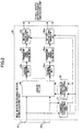
- Fig. 2 is a block diagram showing a multipath receiving signal demodulator 30 according to a first embodiment of the multipath receiving signal demodulator 20 shown in Fig. 1.
- the multipath receiving signal demodulator 30 uses the MMSE algorithm as the primary demodulation method.
- the multipath receiving signal demodulator 30 includes a channel coefficient estimating unit 31, a linear filter coefficient calculating unit 32, a linear filter 33, M reverse spreading units 34 1 through 34 m , M transmission symbol sequence estimating units 35 1 through 35 m , and M multipath receiving signal demodulators 36 1 through 36 m .
- signals r n (t) received by N receiving antennas 21 1 through 21 n are provided to the channel coefficient estimating unit 31, and channel coefficients h m,n,l of paths between the receiving antennas 21 1 through 21 n and the transmitting antennas 11 1 through 11 n (Fig. 1) are estimated.
- the linear filter coefficient calculating unit 32 calculates a coefficient for the linear filter 33, which carries out a filtering process for equalization using the linear filter coefficient.
- the process described above can be realized by signal processing in one of the time domain and the frequency domain; in the following; descriptions are presented about an example wherein signal processing is carried out in the frequency domain.
- the linear filter coefficient calculating unit 32 calculates the linear filter coefficient that simultaneously minimizes delay path components of signals from a desired transmitting antenna and receiving signal components from other transmitting antennas using the estimated channel coefficient h m,n,j as described by Expression 4.
- Expression 4 h ⁇ m , n , l
- an impulse response of a channel (channel impulse response) between the transmitting antennas 11 1 through 11 m and the receiving antennas 21 1 through 21 n is calculated using the estimated channel coefficient as described by Expression 5 ⁇ m,n,l estimated using a pilot channel in the time domain, and a delay time of each reception path t ⁇ t as described by Expression 6.
- N f is a number that is equal to a product of the number of chips equivalent to a block size that are linear-filtered, and the number of times of over-sampling.
- the frequency components h n m f as described by Expression 7 of the channel coefficients of the transmission signals from the transmitting antennas 11 l through 11 m to the receiving antennas 21 l through 21 n are estimated.
- the linear filter coefficients can be determined in accordance with one of ZF criterion and MMSE criterion.
- the linear filter 33 converts each of N sequence received signals into a received signal Y (f) in the frequency domain by carrying out FFT for the N f points. Then, Y (f) is multiplied by W (f) for obtaining estimated values as described by Expression 14 of M transmission signals according to Expression 15, where both collapse of the orthogonality between code channels due to channel fluctuation in the frequency domain (MPII (Multi-Path Interference) in the time domain), and interference between the transmitting antennas are simultaneously equalized (reduced).
- MPII Multi-Path Interference
- the acquired provisional demodulating sequences (primary demodulation sequences) for the transmitting antennas are provided to the corresponding reverse spreading units 34 1 through 34 m .
- the reverse spreading units 34 1 through 34 m carry out reverse spreading of the provisional demodulating sequences for the transmitting antennas with the same spreading signal as used at the time of transmission, and reverse-spread signals z m are output to the corresponding transmission symbol sequence estimating units 35 1 through 35 m .
- the transmission symbol sequence estimating units 35 1 through 35 m carry out one of a hard decision and a soft decision of the corresponding reverse-spread signals z m such that transmission symbol sequences as described by Expression 18 are estimated and output.
- the transmission symbol sequence estimating units 35 1 through 35 m may carry out the hard decision as follows.
- a transmission symbol is expressed by d m,i , where "i" is a symbol candidate number satisfying Expression 19 (1 ⁇ i ⁇ C ), and C expresses the number of transmission symbol points, that is, 4 for QPSK and 16 for 16QAM.
- a symbol candidate number "i" that makes the transmission symbol d m,i closest to Z m (refer to Expression 20) is determined.
- Expression 20 min i z m ⁇ d m , i 2
- the transmission symbol sequence estimating units 35 1 through 35 m may carry out the soft decision as follows.
- the expression ⁇ m,j shown by Expression 23 is a logarithmic likelihood ratio of a bit "i" of the signal from the transmitting antenna 11 m .
- the logarithmic likelihood ratio ⁇ md can be described by Expression 24.
- z m P b m , i ⁇ 1
- S min, ⁇ expresses a symbol candidate having the smallest Euclidean distance from the transmission signal point z m out of a set of symbols whose i-th bit is " ⁇ ", and ⁇ 2 is noise power.
- the multipath receiving signal demodulators 36 l through 36 m receive the transmission symbol sequences as described by Expression 28 ⁇ d ⁇ m that are estimated as described above.
- Expression 29 d ⁇ m the input transmission symbol sequences as described by Expression 29 d ⁇ m are multiplied by the spreading signal and the channel coefficients such that a received signal sequence ⁇ as shown by Expression 30 ⁇ ⁇ Î m,n,l ( t ) ⁇ for every reception path from the transmitting antennas to the receiving antennas is estimated as shown by Expression 31, and output.
- Expression 29 d ⁇ m Expression 30 I ⁇ m , n , l t Expression 31 I ⁇ m , n , l t h ⁇ m , n , l t ⁇ d ⁇ m t ⁇ c t ⁇ ⁇ l
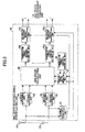
- Fig. 3 is a block diagram showing a multipath receiving signal demodulator 40 that is a second embodiment of the multipath receiving signal demodulator of the present invention.
- an MLD algorithm is used for the multipath receiving signal demodulator 40 as the method of the primary demodulation.
- the multipath receiving signal demodulator 40 includes a channel coefficient estimating unit 41, NxL reverse spreading units 42 through 45, a transmission symbol candidate generating unit 46, a received signal replica generating unit 47, a likelihood calculating unit 48, M transmission symbol sequence estimating units 49 l through 49 m , and M multipath receiving signal demodulators 50 l through 50 m .
- signals r n (t) received by the receiving antennas 21 1 through 21 n are provided to the channel coefficient estimating unit 41, and the channel coefficients h m,n,l of the paths between the receiving antennas 21 1 through 21 n and the transmitting antennas 11 1 through 11 n are estimated.
- the reverse spreading units 42 through 45 which number NxL, perform reverse spreading of the received signals r n (t) with the same spreading signal as the spreading signal used at the time of transmission at the receiving timing of each path, and NxL reverse-spread signals z n, l for the paths of the receiving antennas are obtained.
- the transmission symbol candidate generating unit 46 generates and outputs transmission symbols d m,i corresponding to each transmitting antenna, where "i" is a symbol candidate number that suffices for Expression 32.
- the received signal replica generating unit 47 receives the transmission symbols d m,i generated by the transmission symbol candidate generating unit 46, and the channel coefficients estimated by the channel coefficient estimating unit 41 such that received signal replicas as described by Expression 33 are generated according to Expression 34 and output.
- the likelihood calculating unit 48 receives the reverse-spread signals z n,l and the received signal replicas as described by Expression 35.
- Expression 35 Z ⁇ n , l , i 1 , i 2 , ... , i M
- the likelihood calculating unit 48 calculates errors according to Expression 36.
- the transmission symbol sequence estimating units 49 1 through 49 m receive the generated transmission symbols corresponding to the transmitting antennas, receive the corresponding error signals, determine the minimum of the errors, and estimate transmission symbol sequences, as described by Expression 37, which give the minimum errors.
- Expression 40 ⁇ ⁇ m , i is a logarithmic likelihood ratio of a bit "i" of a transmitting antenna 11 m , and is expressed as follows.
- z 1 , 1 , ... , z N , L P b m , i ⁇ 1
- e min, ⁇ is the minimum value of Expression 42 e i 1 , i 2 , ... , i M wherein the i-th bit is " ⁇ ", and ⁇ 2 (n) expresses noise power,
- the multipath receiving signal demodulators 36 1 through 36 m receive the transmission symbol sequences described by Expression 46 that are estimated as described above.
- Expression 48 I ⁇ m , n , l t
- I ⁇ m , n , l t h ⁇ m , n , l t ⁇ d ⁇ m t ⁇ c t ⁇ ⁇ l
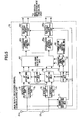
- Fig. 4 is a block diagram of a multipath receiving signal demodulator 50 that is a third embodiment of the multipath receiving signal demodulator.
- the MLD algorithm is used, where the multipath receiving signal demodulator 50 carries out the primary demodulation of the paths in one block.
- the multipath receiving signal demodulator 50 includes a channel coefficient estimating unit 51, NxL reverse spreading units 52 through 55, a QR factorizing unit 56, a Q H operating unit 57, a transmission symbol candidate generating unit 58, a conversion signal replica generating unit 59, a likelihood calculating unit 60, M transmission symbol sequence estimating units 61 1 through 61 m , and M multipath receiving signal demodulators 62 1 through 62 m .
- the channel coefficient estimating unit 51 receives the signals r n (t) received by the receiving antennas 21 1 through 21 n , and the channel coefficients h m,n,l of the paths between the receiving antennas 21 1 through 21 n and the transmitting antennas 11 1 through 11 n are estimated.
- the reverse spreading units 52 through 55 which number NxL, perform reverse spreading of the received signals r n (t) with the same spreading signal as used at the time of transmission at the receiving timing of each path, and NxL reverse-spread signals z n,l of the paths of the receiving antennas are obtained.
- the QR factorizing unit 56 generates a channel matrix as shown by Expression 50, the channel matrix including channel coefficients expressed in NxL rows x M columns, performs QR factorization of the channel matrix, and a Q matrix and an R matrix are output.
- H expresses conjugate complex transposition
- I expresses a unit matrix
- the R matrix turns into an upper triangular matrix having M rows x M columns.
- the Q H operating unit 57 performs operations according to the following expression.
- the transmission symbol candidate generating unit 58 generates the transmission symbols d M,i for the M transmitting antennas 11, and outputs them to the conversion signal replica generating unit 59.
- the conversion signal replica generating unit 59 receives the transmission symbols generated by the transmission symbol candidate generating unit 58, and the R matrix provided by the QR factorizing unit 56 for generating conversion signal replicas as described by Expression 52.
- Expression 52 x ⁇ Mj
- the conversion signal replicas are generated according the following expression, and output.
- Expression 53 x ⁇ Mj r ⁇ MM ⁇ d Mj
- the likelihood calculating unit 60 calculates errors using X M and x ⁇ M j (Expression 54) according to Expression 55.
- Expression 54 x ⁇ M , i
- the likelihood calculating unit 60 receives the generated transmission symbol sequence corresponding to the transmitting antenna 11 M , receives corresponding error signals, holds S M transmission symbols having smaller numbers of errors corresponding to the transmitting antenna 11 M as described by Expression 56, and holds the corresponding errors as expressed by Expression 57.
- the transmission symbol candidate generating unit 58 generates a transmission symbol as described by Expression 58 for the transmitting antenna 11 M-1 , and outputs.
- the conversion signal replica generating unit 59 receives the R matrix, the S M transmission symbol sequences corresponding to the transmitting antenna 11 M , and the transmission symbol corresponding to the transmitting antenna 11 M-1 for generating conversion signal replicas as described by Expression 59 according to Expression 60, and outputs the conversion signal replicas.
- Expression 59 x ⁇ M ⁇ 1 , i M ⁇ 1 , i M
- the likelihood calculating unit 60 performs error calculations according to the following expression.
- the likelihood calculating unit 60 holds S M-1 combinations of the transmission symbol sequences having smaller numbers of errors corresponding to the transmitting antenna 11 M and the transmitting antenna 11 M-1 as described by Expression 62.
- Expression 62 d M ⁇ 1 , i M ⁇ 1 1 , d M , i M 1 ⁇ d M ⁇ 1 , i M ⁇ 1 S M ⁇ 1 , d M , i M S M ⁇ 1
- the likelihood calculating unit 60 holds errors at that time as described by Expression 63.
- Expression 63 e M ⁇ 1 , i M ⁇ 1 1 , i M 1 ⁇ e M ⁇ 1 , i M ⁇ 1 S M ⁇ 1 , i M S M ⁇ 1
- the transmission symbol candidate generating unit 58 generates and outputs the transmission symbols d m,i corresponding to the transmitting antenna 11 m .
- the conversion signal replica generating unit 59 receives the R matrix, the transmission symbol corresponding to the transmitting antenna 11 m , and S m+1 transmission symbol sequences corresponding to the transmitting antennas from 11 m+1 to 11 M for generating conversion signal replicas as described by Expression 64 according to Expression 65; and outputs the conversion signal replicas.
- the likelihood calculating unit 60 performs error calculations according to the following expression.
- the likelihood calculating unit 60 holds S m combinations of the transmission symbol sequences corresponding to the transmitting antennas from 11 m to 11 M as described by Expression 67, the combinations having smaller numbers of errors.
- Expression 67 d m , i m 1 , d m + 1 , i m + 1 1 , ... , d M , i M 1 ⁇ d m , i m S m , d m + 1 , i m + 1 S m , ... , d M , i M S m
- the likelihood calculating unit 60 holds the errors at that time as described by Expression 68.
- Expression 68 e m , i m 1 , i m + 1 1 , ... , i M 1 ⁇ e m , i m S m , i m + 1 S m , ... , i M S m
- Expression 70 e m , i 1 j , i 2 j , ... , i M j
- j is an integer equal to 1 or greater up to CxS 2 .
- the transmission symbol sequence estimating units 61 1 through 61 m receive surviving transmission symbols of the corresponding transmitting antennas, receive corresponding error signals, determine minimum errors, and estimate transmission symbol sequences that give the determined minimum errors.
- the transmission symbol sequence estimating units 61 l through 61 m carry out soft decisions, they are performed as follows.
- e min,v is the smallest of Expression 75 e m , i 1 j , i 2 j , ... , i M j where the i-th bit is " ⁇ ", and ⁇ 2 (n) is noise power.
- the multipath receiving signal demodulators 62 1 through 62 m receive the transmission symbol sequences that are estimated as described above, the transmission symbol sequences being described by Expression 79.
- the multipath receiving signal demodulators 62 1 through 62 m multiply the received transmission symbol sequence as described by Expression 80, the spreading signal, and the channel coefficients as shown by Expression 82 such that received signal sequences, as described by Expression 81, for every reception path between the transmitting antennas and the receiving antennas are estimated and output.
- Expression 82 I ⁇ m , n , l t h ⁇ m , n , l t ⁇ d ⁇ m t ⁇ c t ⁇ ⁇ l
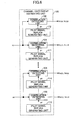
- Fig. 5 is a block diagram showing a multipath receiving signal demodulator 70 that is a fourth embodiment of the multipath receiving signal demodulator.
- the multipath receiving signal demodulator uses the MLD algorithm as the primary demodulation method, wherein each path is individually processed.
- the multipath receiving signal demodulator 70 includes a channel coefficient estimating unit 71, NxL reverse spreading units 72 through 75, L sets of QR factorizing units 76 and 77, L sets of Q H operating units 78 and 79, a transmission symbol candidate generating unit 80, a conversion signal replica generating unit 81, a likelihood calculating unit 82, M transmission symbol sequence estimating units 83 1 through 83 m , and M multipath receiving signal demodulators 84 l through 84 m .
- the channel coefficient estimating unit 71 receives a signal r n (t) received by the N receiving antennas 21 1 through 21 n , and estimates the channel coefficients h m,n,l of each path between the receiving antennas 21 1 through 21 n and the transmitting antennas 11 1 through 11 m .
- the reverse spreading units 72 through 75 which number NxL, perform reverse spreading of the received signal r n (t) with the same spreading signal as used at the time of transmission at the receiving timing of each path, and NxL reverse-spread signals z n,l one for each path of the receiving antennas are obtained.
- an l-th QR factorizing unit generates channel matrices that include channel coefficients of the l-th path, the number of the channel matrices being equal to the number of the paths, and QR factorization of the channel matrices is performed such that a Q matrix and a R matrix are output.
- the transmission symbol candidate generating unit 80 generates the transmission symbols d M,i corresponding to the transmitting antenna 11 M , and outputs them to the conversion signal replica generating unit 81.
- the conversion signal replica generating unit 81 receives the transmission symbols d M,i, receives the R l matrix, and generates conversion signal replicas as described by Expression 86 according to Expression 87, and output the conversion signal replicas.
- Expression 87 x ⁇ M , l , i r ⁇ M M l ⁇ d M , l , i
- the likelihood calculating unit 82 calculates errors according to Expression 89 using x ⁇ M,i and x ⁇ Mjj (Expression 88).
- Expression 88 x ⁇ M , l , i
- the likelihood calculating unit 82 After performing the error calculation, the likelihood calculating unit 82 receives the generated transmission symbol sequences corresponding to the transmitting antenna 11 M , and the corresponding error signals. Then, the likelihood calculating unit 82 holds S M transmission symbols as described by Expression 90 having smaller numbers of errors corresponding to the transmitting antenna 11 M .
- the transmission symbol candidate generating unit 80 generates a transmission symbol as described by Expression 92 corresponding to the transmitting antenna 11 M-1 and outputs the transmission symbol.
- the conversion signal replica generating unit 81 receives the R matrix, the S M transmission symbol sequences corresponding to the transmitting antenna 11 M , and the transmission symbol corresponding to the transmitting antenna 11 M-l for generating conversion signal replicas as described by Expression 93, according to Expression 94, and outputs the conversion signal replicas.
- Expression 93 x ⁇ M ⁇ 1 , l , i M ⁇ 1 , i M
- the likelihood calculating unit 82 performs error calculations by the following expression.
- the likelihood calculating unit B2 holds S m-l combinations as described by Expression 96 of the transmission symbol sequences corresponding to the transmitting antenna 11 M and the transmitting antenna 11 M-1 , the combinations having smaller numbers of errors.
- the likelihood calculating unit 82 holds the errors at that time as described by Expression 97.
- the transmission symbol candidate generating unit 80 generates and outputs the transmission symbols d m,i to the transmitting antenna 11 m .
- the conversion signal replica generating unit 81 receives the R matrix, the transmission symbol corresponding to the transmitting antenna 11 m , and S m+1 transmission symbol sequences corresponding to the transmitting antennas from 11 m+1 to 11 M .
- the conversion signal replica generating unit 81 generates conversion signal replicas as described by Expression 98 according to Expression 99.
- Expression 98 x ⁇ m , i m , i m + 1 , ... , i M
- the likelihood calculating unit 82 performs error calculations according to the following expression.
- the likelihood calculating unit 82 holds S m combinations as described by Formula 101 of the transmission symbol sequences corresponding to the transmitting antennas from 11 m to 11 M , the combinations having smaller numbers of errors.
- Expression 101 d m , i m 1 , d m + 1 , i m + 1 1 , ... , d M , i M 1 ⁇ d m , i m S m , d m + 1 , i m + 1 S m , ... , d M , i M S m
- the likelihood calculating unit 82 holds the errors at that time as described by Expression 102.
- Expression 102 e m , i m 1 , i m + 1 1 , ... , i M 1 ⁇ e m , i m S m , i m + 1 S m , ... , i M S m
- the transmission symbol sequence estimating units 83 1 through 83 m receive surviving transmission symbols and the corresponding error signals corresponding to each transmitting antenna, determine minimum errors, and estimate transmission symbol sequences that give the minimum errors.
- Expression 107 ⁇ ⁇ m , i is a logarithmic likelihood ratio of the bit "i" of the transmitting antenna 11 m , and is described as follows.
- z 1 , 1 , ... , z N , L P b m , i ⁇ 1
- the soft decision symbol as described by Expression 110 is estimated as described by Expression 112 using Expression 111.
- the multipath receiving signal demodulators 84 1 through 84 m receive the transmission symbol sequences as described by Expression 113, the transmission symbol sequences being estimated as described above.
- the transmission symbol sequences as described by Expression 114 are multiplied by the spreading signal and the channel coefficients so that received signal sequences as described by Expression 115 are obtained for every reception path from each transmitting antenna to every receiving antenna are obtained as described by Expression 116, and the received signal sequences are output.
- Expression 114 d ⁇ m Expression 115 I ⁇ m , n , l t Expression 116 I ⁇ m , n , l t h ⁇ m , n , l t ⁇ d ⁇ m t ⁇ c t ⁇ ⁇ l
- Fig. 6 is a block diagram of the channel coefficient estimating unit according to an embodiment of the present invention.
- Figs. 7A and 7B show frame structure examples of the signal transmitted from the transmitting apparatus when the channel coefficient estimating unit is used.
- pilot symbols are periodically inserted into data symbols of the signals transmitted from the transmitting antennas (e.g., transmitting antennas 1 and 2).
- pilot symbol patterns for the transmitting antennas are orthogonally arranged.
- spreading signals (C1, C2) used for spreading the pilot symbols for the transmitting antennas are orthogonally arranged.
- the orthogonal symbol patterns and the orthogonal spreading signals can be generated by using a Walsh sequence of the same length, for example, as the number of the pilot symbols, and the same length as the spreading signals for the pilot symbols.
- a pilot signal sequence of a transmitting antenna m is expressed by p m (n), where n is a chip number.
- the channel coefficient estimating unit 100 is for estimating a channel coefficient of each path between the transmitting antenna m and a receiving antenna n.
- the channel coefficient estimating unit 100 is for 3 transmitting antennas and 4 receiving antennas. That is, the channel coefficient estimating unit 100 includes 3x4 correlation detecting units 101 through 104, and pilot signal replica generating units 111 through 114.
- each of the correlation detecting units and the pilot signal replica generating units includes two or more components, which may be identified by a suffixed serial number when necessary.
- a signal rl is received by the receiving antenna 1, and is provided to the correlation detecting unit 101. Further, the pilot signal replica generating unit 111 generates a pilot symbol sequence pl corresponding to the transmitting antenna 1, which pl is provided to the correlation detecting unit 101.
- the correlation detecting unit 101 estimates the channel coefficient h 1,1,1 between the transmitting antenna 1 and the receiving antenna 1 according to Expression 118, wherein the received signal r1 is multiplied by a complex-conjugate value of the pilot symbol sequence pl of the transmitting antenna 1 in consideration of the receiving timing of a path l, and the obtained product is averaged over the 4 pilot symbol periods.
- r 1 (n) represents the received signal r 1 when a pilot symbol n is received.
- h 1,1,1 is estimated by weight-averaging channel coefficients obtained in two or more pilot symbol periods.
- a second step correlation detecting unit 102 receives the signal r1, and a pilot symbol sequence p 3 of the transmitting antenna 3 generated by a second step pilot symbol replica generating unit 112, and a channel coefficient h 1,3,l is estimated and output.
- a received signal r4 and the pilot symbol sequence p 1 of the transmitting antenna 1 generated by the pilot symbol replica generating unit 113 are provided to the correlation detecting unit 103, and correlation is obtained such that a channel coefficient h 4,1,1 is estimated and output.
- the channel coefficient of all the paths between the 3 transmitting antenna and the 4 receiving antennas are estimated.
- the pilot symbol is multiplexed by the data symbol in the time domain; nevertheless, the channel coefficient estimation can be obtained by the same method in the case where code multiplexing is employed.
- Fig. 8 is a block diagram of a receiving apparatus 200 that is a second embodiment of the receiving apparatus of the present invention.
- the receiving apparatus 200 includes multipath receiving signal demodulators 211 through 213 that are serially connected through multipath interference canceling units 221 1 , 221 2 , 222 1 , 222 2 , 223 1 , and 223 2 (i.e., this example is a 3-stage configuration), and a demodulator 231 that is arranged at the last stage.
- the multipath receiving signal demodulator 211 serving as the first stage, any one of the multipath receiving signal demodulators described with reference to Figs. 2 through 5 can be applied.
- any one of the multipath receiving signal demodulators described with reference to Figs. 2 through 5 can be applied to the multipath receiving signal demodulators 212, 213, and so on, as applicable.
- signals that are input to the p-th multipath receiving signal demodulator (p is an integer equal to 2 or greater) are described by Expression 119.
- Expression 121 This can be described as Expression 121, using the received signals, and output signals (Expression 120) of the (p-1)-th multipath receiving signal demodulator.
- the signals that are input to the p-th multipath receiving signal demodulator are generated by the preceding multipath interference canceling units according to the following expression.
- NxL received signals after multipath interference cancellation obtained according to Expression 121 are described by Expression 122.
- the NxL received signals are provided to a reverse spreading unit (not illustrated) corresponding to the receiving antenna 21 n and the path l.
- a channel coefficient estimating unit (not illustrated) of the p-th stage multipath receiving signal demodulator may use a received signal after multipath interference cancellation as described by Expression 123 instead of the received signal r n (t) when estimating the coefficient h l,l,l, which results in a more accurate channel coefficient estimation.
- the latter stage multipath receiving signal demodulators can use the received signal after multipath interference cancellation, which enables highly accurate channel estimation and transmission symbol sequence estimation.
- the received signal sequence as described by Expression 124 is accurately estimated for every reception path between the transmitting antennas and the receiving antennas.
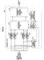
- Fig. 9 is a block diagram of a demodulator 300 that is a first embodiment of the demodulator applicable to the receiving apparatus according to the embodiments of the present invention,
- the present embodiment uses MLD for the demodulator as the demodulating algorithm.
- the demodulator 300 includes a channel coefficient estimating unit 311, NxL reverse spreading units 312 through 315, a transmission symbol candidate generating unit 316, received signal replica generating unit 317, a likelihood calculating unit 318, and a transmitting sequence estimating unit 319. Where a certain unit includes two or more components, they are identified with a suffixed serial number.
- the demodulator 300 is provided with NxL received signals after multipath interference cancellation as described by Expression 125.
- Expression 125 r n , l p t
- the channel coefficient estimating unit 311 estimates the channel coefficients h m,n,l of each path between the receiving antennas and the transmitting antennas (here, it is also possible to use a channel coefficient of a preceding multipath receiving signal demodulator for simplification of the configuration).
- NxL received signals after multipath interference cancellation as described by Expression 126 are provided to a reverse spreading unit corresponding to a receiving antenna 21 n and the path l such that reverse-spread signals z' n,l are obtained.
- the transmission symbol candidate generating unit 316 generates and outputs the transmission symbols d m,i corresponding to each antenna.
- the received signal replica generating unit 317 receives the transmission symbols and the channel coefficients, and generates received signal replicas as described by Expression 127 according to Expression 128, and outputs the received signal replicas to the likelihood calculating unit 318.
- the likelihood calculating unit 318 receives the reverse-spread signals z' n,l from the reverse spreading units 312 through 315, and the received signal replicas as described by Expression 129.
- Expression 129 z ⁇ n , l , i 1 , i 2 , ... , i M
- the likelihood calculating unit 318 performs error calculations according to the following expression.
- the generated transmission symbols corresponding to each transmitting antenna, and the corresponding error signals are provided to the transmitting sequence estimating unit 319 that outputs a likelihood ⁇ i of a bit transmitted by the transmission symbol sequence.
- the bit likelihood based on the error signal may be calculated by any available method.
- bit likelihood described above is provided to a channel decoder (for example, a turbo decoder), etc., so that an information bit sequence is finally obtained.
- a channel decoder for example, a turbo decoder
- Fig. 10 is a block diagram of a demodulator 400 that is a second embodiment of the demodulator of the present invention.
- the second embodiment uses MLD as the demodulating algorithm, wherein paths are grouped into a block for processing.
- the demodulator 400 includes a channel coefficient estimating unit 411, NxL reverse spreading units 412 through 415, a QR factorizing unit 416, a Q H operating unit 417, a transmission symbol candidate generating unit 418, a conversion signal replica generating unit 419, a likelihood calculating unit 420, and a transmitting sequence estimating unit 421. Where a certain unit includes two or more components, they are identified with a suffixed serial number,
- the demodulator 400 receives NxL signals as described by Expression 131 after multipath interference cancellation.
- Expression 131 r n , l p t
- the channel coefficients h m,n,l of each path of between the receiving antennas and the transmitting antennas are estimated by the channel coefficient estimating unit 411. (Here, it is also possible similarly to use a channel coefficient in a preceding multipath receiving signal demodulator for simplification of the configuration).
- the NxL received signals after multipath interference cancellation Expression 132 r n , l p t are provided to the reverse spreading unit corresponding to the receiving antenna 21 n and path l, and reverse-spread signals Z l n,l are obtained.
- the QR factorizing unit 416 generates the following channel matrix (Expression 133) containing channel coefficients, performs QR factorization of the channel matrix, and outputs a Q matrix and a R matrix to the Q H operating unit 417.
- the transmission symbol candidate generating unit 418 generates and outputs the transmission symbols d M,j corresponding to the transmitting antenna 11 M .
- the conversion signal replica generating unit 419 receives the transmission symbols d M,j and the R matrix. Then, the conversion signal replica generating unit 419 generates conversion signal replicas as described by Expression 135 according to Expression 136, and outputs the conversion signal replicas to the likelihood calculating unit 420.
- Expression 136 x ⁇ M , i r ⁇ M M ⁇ d M , i
- the likelihood calculating unit 420 calculates errors between x' M and x ⁇ M.j (Expression 137) according to Expression 138.
- Expression 138 e M , i x ′ M ⁇ x ⁇ M , i 2
- the generated transmission symbol sequences corresponding to the transmitting antenna 11 M and corresponding error signals are provided to the likelihood calculating unit 420 for generating S M transmission symbols as described by Expression 139 having smaller numbers of errors corresponding to the transmitting antenna 11 M .
- the likelihood calculating unit 420 further calculates errors at that time as shown by Expression 140.
- the transmission symbol candidate generating unit 418 generates the transmission symbols as described by Expression 141 corresponding to the transmitting antenna 11 M-1 , and outputs the transmission symbols.
- the conversion signal replica generating unit 419 receives the R matrix, the S M transmission symbol sequences corresponding to the transmitting antenna 11 M and, the transmission symbols corresponding to the transmitting antenna 11 M-1 for generating conversion signal replicas as described by Expression 142 using Expression 143, and the conversion signal replicas are output.
- Expression 142 x ⁇ M ⁇ 1 , i M ⁇ 1 , i M
- the likelihood calculating unit 420 performs error calculations according to the following expression.
- Expression 144 e M ⁇ 1 , i M ⁇ 1 , i M x M ⁇ 1 ⁇ x ⁇ M ⁇ 1 , i M ⁇ 1 , i M 2 + e M , i M
- the likelihood calculating unit 420 holds S M-1 combinations of the transmission symbol sequences corresponding the transmitting antenna 11 M and the transmitting antenna 11 M-1 , the combinations having smaller numbers of errors.
- the likelihood calculating unit 420 holds the errors at that time as described by Expression 146.
- Expression 146 e M ⁇ 1 , i M ⁇ 1 1 , i M 1 ⁇ e M ⁇ 1 , i M ⁇ 1 S M ⁇ 1 , i M S M ⁇ 1
- the transmission symbol candidate generating unit 418 generates and outputs the transmission symbols d m,i corresponding to the transmitting antenna 11 m .
- the conversion signal replica generating unit 419 receives the S m+1 transmission symbol sequences corresponding to the transmitting antennas from 11 m+1 to 11 M , the transmission symbol corresponding to the transmitting antenna 11 m , and the R matrix for generating conversion signal replicas as described by Expression 147 according to Expression 148, and output the conversion signal replicas.
- the likelihood calculating unit 420 performs error calculations according to the following expression.
- Expression 149 e m , i m , ... , i m ⁇ 1 , i M x ′ m ⁇ x ⁇ m , i m , i m + 1 , ... , i M 2 + e m + 1 , i m + 1 , i m + 2 , ... , i M
- the likelihood calculating unit 420 holds S m combinations as described by Expression 150 of the transmission symbol sequences corresponding to the transmitting antennas from 11 m to 11 N , the combinations having smaller numbers of errors.
- Expression 150 d m , i m 1 , d m + 1 , i m + 1 1 , ... , d M , i M 1 ⁇ d m , i m S m , d m + 1 , i m + 1 S m , ... , d M , i M S m
- the likelihood calculating unit 420 holds the errors at that time as described by Expression 151.
- Expression 151 e m , i m 1 , i m + 1 1 , ... , i M 1 ⁇ e m , i m S m , i m + 1 S m , ... , i M S m
- the transmitting sequence estimating unit 421 receives the surviving transmission symbols corresponding to each transmitting antenna and the corresponding error signals, and outputs a likelihood ⁇ i of a bit transmitted by the transmission symbol sequence,
- the bit likelihood based on the error signal can be calculated using any available method.
- bit likelihood described is provided to a channel decoder (for example, a turbo decoder) etc., and an information bit sequence is finally obtained.
- a channel decoder for example, a turbo decoder
- Fig. 11 shows a demodulator 500 that is a third embodiment of the demodulator of the present invention.
- each path is processed by a demodulating algorithm that employs MLD.
- the demodulator 500 includes a channel coefficient estimating unit 511, NxL reverse spreading units 512 through 515, L QR factorizing units 516 and 517, L Q H operating units 518 and 519, a transmission symbol candidate generating unit 520, a conversion signal replica generating units 521, a likelihood calculating units 522, and a transmitting sequence estimating unit 523. Where a certain unit includes two or more components, they are identified with a suffixed serial number.
- the demodulator 500 receives NxL input signals that are the received signals after multipath interference cancellation as described by Expressed 155. Expression 155 r n , l p t
- the channel coefficient estimating unit 511 estimates the channel coefficients h m,n,l of each path between the receiving antennas and the transmitting antennas. (Here, it is possible to use a channel coefficient of a preceding multipath receiving signal demodulator for simplification of the configuration).
- NxL received signals after multipath interference cancellation as described by Expression 156 are provided to the reverse spreading unit corresponding to the receiving antenna 21 n and the path l so that the reverse-spread signals z' n,l are obtained.
- the l-th QR factorizing unit generates the following channel matrix containing channel coefficients of the l-th path for each path, performs QR factorization of the channel matrix so that the Q matrix and the R matrix are output.
- H expresses a conjugate complex transposition
- I expresses a unit matrix.
- R l matrix turns into an upper triangular matrix having M rows x M columns.
- the transmission symbol candidate generating unit 520 generates the transmission symbols d M,i corresponding to the transmitting antenna 11 M , and outputs the transmission symbols d M,i to the conversion signal replica generating unit 521.
- the conversion signal replica generating unit 521 receives the transmission symbols d M,i and the R l matrix so that the conversion signal replicas as described by Expression 159 are generated according to Expression 160, and output.
- Expression 160 x ⁇ M , l , i r ⁇ M M l ⁇ d M , l , i
- the likelihood calculating unit 522 performs error calculations using x' M,l and the conversion signal replicas as described by Expression 161 according to Expression 162.
- Expression 161 x ⁇ M , l , i
- the likelihood calculating unit 522 receives generated transmission symbol sequences corresponding to the transmitting antenna 11 M , and the corresponding error signals.
- the likelihood calculating unit 522 holds S M transmission symbol sequences having smaller numbers of errors corresponding to the transmitting antenna 11 M as described by Expression 163.
- the likelihood calculating unit 522 holds the errors at that time as described by Expression 164.
- the transmission symbol candidate generating unit 520 generates and outputs transmission symbols d M-l,i corresponding to the transmitting antenna 11 M-l .
- the conversion signal replica generating unit 521 receives the R matrix, the S M transmission symbol sequences corresponding to the transmitting antenna 11 M and the transmission symbol corresponding to the transmitting antenna 11 M-l for generating conversion signal replicas as described by Expression 165 according to Expression 166, and outputting the conversion signal replicas.
- Expression 165 x ⁇ M ⁇ 1 , l , i M ⁇ 1 , i M
- the likelihood calculating unit 522 performs error calculations according to the following expression.
- the likelihood calculating unit 522 holds S M-1 combinations as described by Expression 168 of the transmission symbol sequences corresponding the transmitting antenna 11 M and the transmitting antenna 11 M-1 having smaller numbers of errors.
- the likelihood calculating unit 522 holds the errors at that time as described by Expression 169.
- Expression 169 e M ⁇ 1 , i M ⁇ 1 1 , i M 1 ⁇ e M ⁇ 1 , i M ⁇ 1 S M ⁇ 1 , i M S M ⁇ 1
- the transmission symbol candidate generating unit 520 generates and outputs the transmission symbols d m,i corresponding to the transmitting antenna 11 m .
- the conversion signal replica generating unit 521 receives the R matrix, S m+1 transmission symbol sequences corresponding to the transmitting antennas m+1 to M, and the transmission symbol corresponding to the transmitting antenna 11 m for generating conversion signal replicas as described by Expression 170 according to Expression 171, and output.
- Expression 170 x ⁇ m , i m , i m + 1 , ... , i M
- the likelihood calculating unit 522 performs error calculations according to the following expression.
- The,likelihood calculating unit 522 holds S m combinations of the transmission symbol sequences corresponding to the transmitting antennas 11 m to 11 M having smaller numbers of errors as described by Expression 173.
- Expression 173 d m , i m 1 , d m ⁇ 1 , i m + 1 1 , ... , d M , i M 1 ⁇ d m , i m S m , d m + 1 , i m + 1 S m , ... , d M , i M S m
- the likelihood calculating unit 522 holds the errors at that time as described by Expression 174.
- Expression 174 e m , i m 1 , i m + 1 1 , ... , i M 1 ⁇ e m , i m S m , i m + 1 S m , ... , i M S m
- the transmitting sequence estimating unit 523 receives the surviving transmission symbols corresponding to each transmitting antenna obtained by the L likelihood calculating units, and the corresponding error signals; and outputs a likelihood ⁇ i transmitted by the transmission symbol sequence based on the sum of L error signals.
- the bit likelihood based on the error signals can be calculated using any available method.
- bit likelihood described above is provided to a channel decoder (for example, turbo decoder), etc., and, the information bit sequence is finally obtained.
- a channel decoder for example, turbo decoder
- Fig. 12 is a block diagram of a receiving apparatus 600 that is a third embodiment of the receiving apparatus according to the present invention.
- the receiving apparatus 600 constitutes a radio communications system wherein a transmitting apparatus (not illustrated) performs serial parallel conversion of a transmitting data bit sequence into M transmitting sequences, which sequences are modulated with the same frequency and the same spreading code group, and are simultaneously transmitted by N code multicode channels from M transmitting antennas.
- the receiving apparatus 600 includes multipath receiving signal demodulators 611 through 614 corresponding to each code channel (each of code channels 1 and 2 in this example) for a predetermined number of stages, demodulators 621 and 622 corresponding to each code channel, and multipath interference canceling units 615 through 618.
- the multipath interference canceling units 615 through 618 are inserted between one and another of the multipath receiving signal demodulators 611 through 614, or between one of the multipath receiving signal demodulators 611 through 614 and one of the demodulators 621 and 622, as applicable.
- Expression 178 I ⁇ m , n , l , k p p h ⁇ m , n , l i ⁇ d ⁇ m p t ⁇ c k t ⁇ ⁇ l
- k represents a code number that is limited by Expression 179.
- Expression 179 1 ⁇ k ⁇ N code c k t
- the multipath interference canceling units 615 and 616 receive the signals r n (t), and demodulated signal sequences of all the code channels as described by Expression 180 through corresponding adders 631 through 634.
- the multipath interference canceling units 615 and 616 then generate received signals after multipath interference cancellation as described by Expression 181 according to Expression 182.
- the multipath receiving signal demodulators 613 and 614 that are the second stage of the corresponding code channels receive the received signals after multipath interference cancellation as described by Expression 183.
- the final received signals after multipath interference cancellation generated as above are provided to the corresponding demodulators 621 and 622 of each code channel, and the demodulators 621 and 622 output the likelihood of a bit being transmitted by the transmission symbol sequence in each code channel.
- Fig. 13 shows computer simulation results of throughput property (vertical axis) over average receiving Eb/N o per receiving antenna (signal energy to the noise power density per 1 bit of information) (horizontal axis) of various demodulating methods used by the receiving apparatus; namely, the conventional MLD, the conventional 2-dimensional MMSE, and the method of the present invention.
- the receiving apparatus applied to the computer simulation includes two stages of the multipath receiving signal demodulators, where the configuration of Fig. 2 is used for the first stage, and the configuration of Fig. 4 is used for the second. Further, as for the multipath, a two-path model is used where both paths provide the same average received power.
- a coding rate of channel coding using turbo coding is indicated by "R"
- solid lines represent properties according to the present invention (QR-MLD with two-stage MPIC)
- dotted lines represent properties of the conventional MMSE
- X marks represent properties of the conventional MLD.
- • and ⁇ marks represent the average receiving Eb/No per receiving antenna in the case of MIMO multiplexing (4 transmitting antenna, 4 receiving antennas) using QPSK modulation;
- ⁇ and ⁇ marks represent the average receiving Eb/No per receiving antenna in the case of MIMO multiplexing using 16QAM modulation.
- Fig. 13 average received power Eb/No required for obtaining a certain level of the throughput is greatly reduced by using the configuration of the receiving apparatus according to the embodiments of the present invention as compared with the case where the conventional signal separating method is used. That is, the receiving apparatus of the present invention requires less transmission power to obtain the same throughput as conventional apparatuses. In other words, the same transmitted power provides a greater throughput with the receiving apparatus according to the embodiments of the present invention.
- the MIMO multiplexing when used for simultaneous transmission of different data from two or more transmitting antennas in order to increase an information bit rate in a CDMA system, highly accurate signal separation is obtained, reducing-the multipath interference. Consequently, the receiving bit error rate and receiving packet error rate in a multipath fading environment are greatly reduced, and the throughput (information bit transmission rate that provides no errors) is greatly raised.
- multipath receiving signal demodulator has been described as using algorithms (for example, a program that describes the algorithm) such as MMSE and MLD, other algorithms such as QR-MLD algorithm can be more desirable for obtaining accurate signal separation by a realistic amount of calculations.
- algorithms for example, a program that describes the algorithm
- QR-MLD algorithm can be more desirable for obtaining accurate signal separation by a realistic amount of calculations.
- the receiving apparatus has been described as being used in a radio communications system, the receiving apparatus can be applied to a base station of a mobile communications system. Further, the algorithm of the present invention can be applied to a so-called software radio base station, to which the algorithm is selectively downloaded to a radio apparatus through a radio circuit or a wire circuit for changing properties of the radio apparatus.
- the present invention is applicable to a radio communications system that demodulates signals using two or more antennas.
Landscapes
- Engineering & Computer Science (AREA)
- Computer Networks & Wireless Communication (AREA)
- Signal Processing (AREA)
- Physics & Mathematics (AREA)
- Mathematical Physics (AREA)
- Radio Transmission System (AREA)
- Input Circuits Of Receivers And Coupling Of Receivers And Audio Equipment (AREA)
- Noise Elimination (AREA)
- Radar Systems Or Details Thereof (AREA)
- Reduction Or Emphasis Of Bandwidth Of Signals (AREA)
- Alarm Systems (AREA)
Abstract
Description
- The present invention relates to a receiving apparatus, a receiving method, and a radio communications system for demodulating (separating) a signal using two or more antennas.
- In the fourth generation mobile communications, a radio communications method that is capable of providing a high transmission speed is required. From this viewpoint, a MIMO (multiple inputs and multiple outputs, i.e., two or more I/O) multiplexing method attracts attention, wherein each of antennas (for transmission and reception) transmits a different signal from others at the same time and the same frequency using MIMO channels.
- The MIMO multiplexing method is described with reference to Fig. 14 that shows the configuration of a MIMO communication system using two or more antennas. According to this system, the transmission speed is increased in proportion to the number of transmitting-antennas without increasing a transmission bandwidth by antennas 10111 through 1011N transmitting respective different signals at the same frequency, and antennas 10211 through 1021N simultaneously receiving all the different signals (for example, Non-patent Reference 1).
- Further BLAST (Bell Labs Layered Space - Time) is one of the technologies generically named MIMO. According to BLAST, different signals are simultaneously transmitted at the same frequency, i.e., a parallel transmission, from two or more transmitting antennas; and, on the receiving side, the signals are separated by diversity reception that is controlled by interference suppression and by a replicas subtraction (for example, Non-patent Reference 1).
- As described above, while it is possible to realize a high transmission speed by the MIMO multiplexing method, since different data sequences are transmitted from the transmitting antennas at the same frequency and at the same time slot, a receiving unit is required to separate the signals in order to extract the data sequences transmitted from each transmitting antenna from the received signal for demodulation.
- Various methods are proposed for separating the MIMO multiplexed signals. For example, according to a signal separation algorithm using a linear filter such a minimum mean square error (MMSE) method, and a zero forcing (ZF) method, signals received by antennas, the number of which antennas is equal to or greater than the number of the transmitting antennas, are compounded such that receiving power from transmitting antennas other than a target transmitting antenna is suppressed (minimized). According to this method, the amount of operations on the receiving side is relatively small.
- Further, according to a signal separation algorithm using a maximum likelihood detection method (MLD), replica candidates of signals received from each transmitting antenna are generated, and a replica of a received signal that gives the smallest Euclidean distance between the received signal and a sum of the replica candidates of the signals received from all the transmitting antennas is obtained. In this way, the MLD method gives the most probable signal sequence of each transmitting antenna. The MLD method provides more accurate signal separation and superior demodulation performance as compared with the MMSE method; however, the amount of operations required of signal separation exponentially increases as the number of the antennas is increased. Then, a proposal (for example, Non-patent Reference 2) is made wherein the amount of operations is decreased in the MLD by greatly decreasing the number of signal point candidates for calculating the square Euclidean distance using QR factorization.
- By the way, conventional direct spreading (DS) CDMA is a communication method wherein a secondary modulation is performed for spectrum - spreading a signal that is modulated by conventional information data with a high - speed spreading signal such that two or more parties can communicate using the same frequency band. In the radio communications using DS-CDMA, as the bandwidth used for signal transmission becomes great, multipath fading (frequency selective fading) is generated, and a transmission signal is received through two or more paths (multipath) having different propagation delay times.
- While receiving quality can be improved in DS-CDMA with a rake reception method, wherein two or more signals through the multipath are compounded, interference (multipath interference) is generated between different paths. For this reason, the receiving quality improvement by the rake reception method is offset by the multipath interference.
- The magnitude of the multipath interference is proportional to the inverse number of a spreading rate that is defined by a ratio of a chip rate (representing a speed of multiplication by the spreading signal) to a symbol rate of information symbols. For this reason, if the spreading rate is brought close to 1 in an attempt to increase an information bit rate, degradation of the receiving quality due to the multipath interference becomes dominant rather than the improvement obtained by the rake reception method. This poses a problem in that the receiving quality is degraded when transmitting at a high speed. Then, in an attempt to cope with the problem, a multipath interference canceller is proposed (for example, Non-patent Reference 3).
- According to the multipath interference canceller as disclosed by Non-patent Reference 3, high quality reception under a multipath environment is realized by
estimating a received signal sequence for every path based on an signal sequence that is estimated by a provisional rake receiving result and a channel coefficient (complex envelope of a propagation path) of each reception path,
deducting all estimated signal sequences obtained from paths other than a certain path (a target path) from the received signal, and
repeating the deducting operation for all the paths. In this way, the multipath interference of the signal of every path is reduced. Then, using the signals, for the multipath interference of which signals have been reduced, a final rake reception is carried out. - Further, 2-dimensional MMSE is proposed as a signal separating method, whereby the multipath interference in MIMO multiplexing in the radio communications using DS-CDMA is reduced, With the 2-dimensional MMSE, both interference generated by received signals from other transmitting antennas and multipath interference are simultaneously reduced.
- [Non-patent Reference 1] G. J. Foschini, Layered Space-Time Architecture for Wireless Communication in a Fading Environment When Using Multiple Antennas, Bell Labs Technical Journal, Vol. 1, No. 2, autumn 1996, .
- [Non-patent Reference 2] Bin Dong, Xaodong Wang, and Amaud Doucet, "Sampling- based Near-optimal MIMO demodulation Algorithms" in Proc. 42nd IEEE Conference on Decision and Control, Hawaii, Dec., 2003
- [Non-patent Reference 3] K. Higuchi, A. Fujiwara, and M. Sawahashi, "Multipath Interference Canceller for High-Speed Packet Transmission With Adaptive Modulation and Coding Scheme in W-CDMA Forward Link, "IEEE J. Select. Areas Commun., Vol.20, No.2, pp.419 through 432, February 2002.
- [Non-patent Reference 4] Frederik Petre et. al, "Combined Space-Time Chip Equalization And Parallel Interference Cancellation For DS-CDMA Downlink With Spatial Multiplexing" in Proc. IEEE PIMRC 2002.
- When applying the MIMO multiplexing method as described above for increasing the information bit rate of the radio communications using DS-CDMA, the spreading rate should be made small such that the information bit rate per transmitting antenna can be increased. In this case, as shown in Fig. 15, there are generated
mutual interference between the transmitting antennas of the paths of the same receiving timing (indicated by (a) in Fig. 15), and
the multipath interference (indicated by (b) and (c) in Fig. 15) from the multiple paths of all the transmitting antennas of different receiving timings. For this reason, accuracy of the signal separation on the receiving side is greatly degraded due to the multipath interference as in the case of the rake reception with one antenna transmission described above. - The proposed multipath interference canceller described above is configured in consideration of a signal transmitted from only one antenna. If this is applied to MIMO multiplexing, accurate estimation of a signal sequence with the rake reception cannot be obtained.
- Further, as evident from Fig. 15, the multipath interference in the case of MIMO multiplexing is generated not only by one antenna, but also by two or more antennas. Accordingly, it is necessary to reduce the multipath interference due to multiple antennas for highly accurate reception.
- However, the signal separation of the MMSE method theoretically is poorer than the MLD method, and a desired performance cannot be obtained on the receiving side. Further, according to the 2-dimensional MMSE method, a filter coefficient is controlled in an attempt to reduce both the interference generated by the received signals from other transmitting antennas and the multipath interference. For this reason, signal separation accuracy is further degraded, posing a problem.
- The present invention is made in view of the problems described above, and offers a receiving apparatus, a receiving method, and a radio communications system that are capable of realizing highly accurate signal separation by reducing degradation of the receiving quality due to the multipath interference.
- According to an embodiment of the present invention, a receiving apparatus is provided for receiving a signal using the CDMA method, wherein signals are transmitted from M transmitting antennas (M is a positive integer), and received by N receiving antennas (N is a positive integer). The receiving apparatus includes;
- multipath receiving signal demodulating units configured to
- demodulate (primary demodulation) the signals received by the receiving antennas,
- estimate the transmitted signals from the transmitting antennas, and
- obtain a received signal of each path of the receiving antennas in a multipath environment based on the estimation;
- multipath interference canceling units configured to deduct the obtained received signals of paths other than a target path from the signals received by the receiving antennas to obtain a multipath interference cancelled signal; and
- a demodulator configured to perform a secondary demodulation of the multipath interference cancelled signal output by the multipath interference canceling unit.
- According to an aspect of the present invention, the multipath receiving signal demodulating unit of the receiving apparatus carries out the primary demodulation using a minimum mean square error (MMSE) method.
- According to an aspect of the present invention, the multipath receiving signal demodulating unit of the receiving apparatus carries out the primary demodulation using a maximum likelihood detection (MLD) method.
- According to an aspect of the present invention, the multipath receiving signal demodulating unit of the receiving apparatus carries out the primary demodulation of two or more paths in one block using the maximum likelihood detection method that uses QR factorization.
- According to an aspect of the present invention, the multipath receiving signal demodulating unit of the receiving apparatus carries out the primary demodulation of each of the paths using the maximum likelihood detection method that uses QR factorization.
- According to an aspect of the present invention, the multipath receiving signal demodulating unit of the receiving apparatus controls the amplitude of the received signal based on the correctness likelihood of a transmission symbol sequence estimated using any one of the methods described above.
- According to an aspect of the present invention, the multipath receiving signal demodulating unit of the receiving apparatus estimates a channel coefficient using a known pilot signal transmitted from the M transmitting antennas.
- According to an aspect of the present invention, the receiving apparatus includes a predetermined number of multipath receiving signal demodulating units, and a predetermined number of multipath interference canceling units connected in stages (cascaded).
- According to an aspect of the present invention, when the receiving apparatus includes the staged connection of the multipath receiving signal demodulating units, the estimated channel coefficient is updated in each stage based on the known pilot signal transmitted from the M transmitting antennas using the multipath interference cancelled signal.
- Further, according to an aspect of the present invention, the demodulating unit of the receiving apparatus carries out the secondary demodulation using the maximum likelihood detection method.
- According to an aspect of the present invention, the demodulating unit of the receiving apparatus carries out the secondary demodulation of two or more paths in one block using the maximum likelihood detection method that uses QR factorization.
- According to an aspect of the present invention, the demodulating unit of the receiving apparatus carries out the secondary demodulation of each of the paths using the maximum likelihood detection method that uses QR factorization.
- According to an aspect of the present invention,
when code multiplexed signals are transmitted from the M transmitting antennas, the multipath receiving signal demodulating unit of the receiving apparatus carries out the primary demodulation of a signal received by each receiving antenna, and the received signal of each path for every receiving antenna is obtained for every spreading signal,
the multipath interference canceling unit generates a signal by deducting the obtained signal corresponding to all the spreading signals of paths other than a target path from the signals received by each of the receiving antennas to obtain a multipath interference cancelled signal, and
the demodulating unit carries out a secondary demodulation of the multipath interference cancelled signal for every spreading signal. - According to the embodiment of the present invention, when different data are simultaneously transmitted from two or more transmitting antennas using the CDMA method, highly accurate-separation of the signals transmitted from different transmitting antennas, the multipath interference of which signals is reduced, can be realized. Consequently, the receiving quality in the multipath fading environment is greatly improved.
-
- Fig. 1 is a block diagram of a radio communications system including a receiving apparatus according to an embodiment of the present invention.
- Fig. 2 is a block diagram of a first embodiment of a multipath receiving signal demodulator.
- Fig. 3 is a block diagram of a second embodiment of the multipath receiving signal demodulator.
- Fig. 4 is a block diagram of a third embodiment of the multipath receiving signal demodulator.
- Fig. 5 is a block diagram of a fourth embodiment of the multipath receiving signal demodulator.
- Fig. 6 is a block diagram of a channel coefficient estimating unit.
- Fig. 7A is a data map showing an example of a frame structure of a signal transmitted from a transmitting apparatus.
- Fig. 7B is a data map showing another example of the frame structure of the signal transmitted from the transmitting apparatus.
- Fig. 8 is a block diagram of a second embodiment of the receiving apparatus according to the present invention.
- Fig. 9 is a block diagram of a first embodiment of a demodulator according to the present invention.
- Fig. 10 is a block diagram of a second embodiment of the demodulator according to the present invention.
- Fig. 11 is a block diagram of a third embodiment of the demodulator according to the present invention.
- Fig. 12 is a block diagram of a third embodiment of the receiving apparatus according to the present invention.
- Fig. 13 is a graph showing results of a computer simulation about the present invention.
- Fig. 14 is a block diagram of a MIMO communication system using two or more antennas.
- Fig. 15 is a schematic diagram showing that accuracy of demodulation (signal separation) deteriorates due to multipath interference in the case of MIMO multiplexing of DS-CDMA.
-
- 1 Radio Communications System
- 10 1010 Transmitting apparatus
- 111 through 11m, 10111 through 1011n Transmitting antenna
- 20, 200, 600, 1020 Receiving apparatus
- 211 through 21n, 10211 through 1021n Receiving antenna
- 22, 30 through 50, 70, 211 through 213, 611 through 614 Multipath receiving signal demodulator
- 23, 2211, 2212, 2221, 2222, 2231, 2232, 615 through 618 Multipath interference canceling unit
- 24, 300, 400, 500, 621, 622 Demodulator
- 31, 41, 51, 71, 100, 311, 411, 511 Channel coefficient estimating unit
- 32 Linear filter coefficient Calculating unit
- 33 Linear filter
- 341 through 34m, 42 through 45, 52 through 55, 72 through 75, 312 through 315, 412 through 415, 512 through 515 Reverse spreading unit
- 351 through 35m Transmission symbol sequence estimating unit
- 361 through 36m, 501 through 50m, 621 through 62m, 841 through 84m Multipath receiving signal demodulator
- 46, 58, 80, 316, 418, 520 Transmission symbol candidate generating unit
- 47, 317 Received signal replica generating unit
- 48, 60, 82, 318, 420, 522 Likelihood calculating unit
- 491 through 49m, 611 through 61m, 831 through 83m Transmission symbol sequence estimating unit
- 56, 76, 77, 416, 516, 517 QR factorizing unit
- 57, 78, 79, 417, 518, 519 QH operating unit
- 59, 81, 419, 521 Conversion signal replica generating unit
- 101 through 104 Correlation detecting unit
- 111 through 114 Replicas signal generating unit
- 319, 421, 523 Transmitting sequence estimating unit
- 631 through 63.4, 641 through 644 Adder
- Hereafter, embodiments of the present invention are described with reference to the attached drawings.
- Fig. 1 is a block diagram of a
radio communications system 1 including a receivingapparatus 20 according to the embodiment of the present invention. Theradio communications system 1 according to the present invention uses one of a MIMO channel and a MISO (Multi Input Single Output, i.e., two or more inputs and a single output, using only one receiving antenna) channel in DS-CDMA. In the following, an example wherein a signal is transmitted using a MIMO channel is described. - As shown in Fig. 1, the
radio communications system 1 includes a transmittingapparatus 10 and the receivingapparatus 20 that are connected through radio communications. The transmittingapparatus 10 carries out serial to parallel conversion of a data bit sequence that is input for transmission into M transmitting sequences, modulates the transmitting sequences (data modulation) using the same frequency band and the same spreading signal, and simultaneously transmits the modulated sequences from M transmitting antennas 111 through 11m as transmission signals. Each of the transmission signals is propagated through L paths (multipath), and is received by N receiving antennas 21l through 21n that are connected to the receivingapparatus 20. The receivingapparatus 20 includes a multipathreceiving signal demodulator 22, N multipath interference canceling units 23l through 23n, and ademodulator 24. - Here, a transmission signal from a transmitting antenna 11m connected to the transmitting
apparatus 10 is expressed by Sm(t), and a received signal received by a receiving antenna 21n connected to the receivingapparatus 20 is expressed by rn(t). Then, rn (t) can be described as follows.
- Here, hm,n,ℓ(t) is a channel coefficient of a reception path ℓ when receiving a transmission signal from the transmitting antenna 11m by the receiving antenna 21n, and τℓ is a propagation delay time of the reception path ℓ.
- Next, operations of the receiving
apparatus 20 according to the present invention are described. - With the receiving
apparatus 20, signals rn(t) received by the receiving antennas 21l through 21n are provided to the multipathreceiving signal demodulator 22. The multipathreceiving signal demodulator 22 carries out provisional signal separation (a primary demodulation) based on the signals received by the N receiving antennas 211 through 21n such that received signal sequences as described by the followingExpression 2 for the reception paths between the transmitting antennas 111 through 11m and the receiving antennas 211 through 21n are estimated and output.
- An algorithm for carrying out the primary demodulation is described below.
- Next, the signals received by the receiving antennas 211 through 21n, and the received signal sequences of every reception path from the transmitting antennas 111 through 11m are provided to the corresponding multipath interference canceling units 231 through 23n, The multipath interference canceling units 231 through 23n (that number N, the same number as the receiving antennas 211 through 21n) obtain received signals after the multipath interference cancellation rn,ℓ(t) by deducting all the received signals of other paths than a target path from the received signal according to the following expression, and output the multipath interference cancelled signals rn,ℓ (t).


- The
demodulator 24 receives NxL multipath interference cancelled signals rn,ℓ(t) provided by the multipath interference canceling units 231 through 23n. Thedemodulator 24 outputs a secondary demodulation result that is a likelihood λi, the likelihood being one of a likelihood of the transmission symbol sequence and a likelihood of a bit transmitted by the transmission symbol sequence. The secondary demodulation result is provided to an error correction (channel) decoder, such as a Viterbi decoder and a turbo decoder, for decoding. - As described above, according to the present embodiment, the multipath receiving
signal demodulator 22 carries out the primary demodulation, and the transmission signals are estimated. Then, the received signal for every path is estimated by multiplying the estimated received signal and the channel fluctuation values (channel coefficients). Then, the multipath interference canceling units 23 subtract estimated received signals other than the signal received through the target path. In this way, thedemodulator 24 is able to demodulate the received signal after removing multipath interference, and signal separation can be performed with high accuracy. - That is, even if the DS-CDMA method is applied to an uplink, and the MIMO multiplexing method is used, degradation of the signal separation accuracy resulting from the multipath interference can be avoided.
- Fig. 2 is a block diagram showing a multipath
receiving signal demodulator 30 according to a first embodiment of the multipathreceiving signal demodulator 20 shown in Fig. 1. According to the first embodiment, the multipath receivingsignal demodulator 30 uses the MMSE algorithm as the primary demodulation method. - As shown in Fig. 2, the multipath receiving
signal demodulator 30 includes a channelcoefficient estimating unit 31, a linear filter coefficient calculating unit 32, alinear filter 33, M reverse spreading units 341 through 34m, M transmission symbol sequence estimating units 351 through 35m, and M multipath receiving signal demodulators 361 through 36m. - According to the multipath
receiving signal demodulator 30 of the first embodiment, signals rn(t) received by N receiving antennas 211 through 21n are provided to the channelcoefficient estimating unit 31, and channel coefficients hm,n,ℓ of paths between the receiving antennas 211 through 21n and the transmitting antennas 111 through 11n (Fig. 1) are estimated. - Then, the linear filter coefficient calculating unit 32 calculates a coefficient for the
linear filter 33, which carries out a filtering process for equalization using the linear filter coefficient. The process described above can be realized by signal processing in one of the time domain and the frequency domain; in the following; descriptions are presented about an example wherein signal processing is carried out in the frequency domain. - The linear filter coefficient calculating unit 32 calculates the linear filter coefficient that simultaneously minimizes delay path components of signals from a desired transmitting antenna and receiving signal components from other transmitting antennas using the estimated channel coefficient h m,n,j as described by
Expression 4.
- Specifically, an impulse response of a channel (channel impulse response) between the transmitting antennas 111 through 11m and the receiving antennas 211 through 21n is calculated using the estimated channel coefficient as described by
Expression 5 ĥ m,n,ℓ estimated using a pilot channel in the time domain, and a delay time of each reception path t̂ t as described by Expression 6.

- Next, FFT for Nf points is carried out on the channel impulse response obtained as described above. Here, Nf is a number that is equal to a product of
the number of chips equivalent to a block size that are linear-filtered, and the number of times of over-sampling. In this way, the frequency components

- Using this, an estimated value of a channel matrix having N rows x M columns as described by Expression 9 is obtained as described by Expression 8.
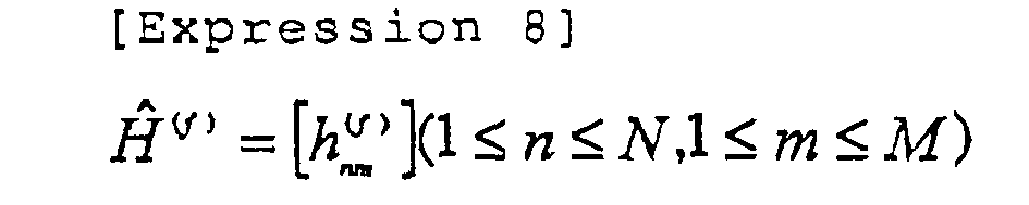

- Using
Expression 10, linear filtering coefficients are calculated for every frequency component after FFT.
- The linear filter coefficients can be determined in accordance with one of ZF criterion and MMSE criterion.
- For example, the linear filter coefficients by the ZF criterion are obtained according to the following expression.

- Further, the linear filter coefficients by the MMSE criterion are obtained according to the following expression.

- Here, the last term of Expression 12 that is described by Expression 13 represents a noise component.

- Next, the
linear filter 33 converts each of N sequence received signals into a received signal Y(f) in the frequency domain by carrying out FFT for the Nf points. Then, Y(f) is multiplied by W(f) for obtaining estimated values as described by Expression 14 of M transmission signals according toExpression 15, where both
collapse of the orthogonality between code channels due to channel fluctuation in the frequency domain (MPII (Multi-Path Interference) in the time domain), and
interference between the transmitting antennas
are simultaneously equalized (reduced).

- In addition

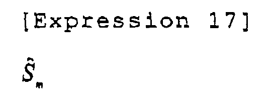
- The acquired provisional demodulating sequences (primary demodulation sequences) for the transmitting antennas are provided to the corresponding reverse spreading units 341 through 34m. The reverse spreading units 341 through 34m carry out reverse spreading of the provisional demodulating sequences for the transmitting antennas with the same spreading signal as used at the time of transmission, and reverse-spread signals zm are output to the corresponding transmission symbol sequence estimating units 351 through 35m. The transmission symbol sequence estimating units 351 through 35m carry out one of a hard decision and a soft decision of the corresponding reverse-spread signals zm such that transmission symbol sequences as described by Expression 18 are estimated and output.

- The transmission symbol sequence estimating units 351 through 35m may carry out the hard decision as follows.
- Here, a transmission symbol is expressed by dm,i, where "i" is a symbol candidate number satisfying Expression 19 (1≤i≤C), and C expresses the number of transmission symbol points, that is, 4 for QPSK and 16 for 16QAM.

- A symbol candidate number "i" that makes the transmission symbol dm,i closest to Zm (refer to Expression 20) is determined.

- Using the "i" determined as above, a determination of Expression 21 is made.

- Alternatively, the transmission symbol sequence estimating units 351 through 35m may carry out the soft decision as follows.
- First, a bit sequence for the soft decision is obtained according to
Expression 22.
- Here, the expression Λ̂ m,j shown by Expression 23 is a logarithmic likelihood ratio of a bit "i" of the signal from the transmitting antenna 11m.

- The logarithmic likelihood ratio Λ̂ md can be described by
Expression 24.
- Here, Smin,ν expresses a symbol candidate having the smallest Euclidean distance from the transmission signal point zm out of a set of symbols whose i-th bit is "ν", and σ2 is noise power.
- Then, a soft decision symbol


- Finally, the multipath receiving signal demodulators 36l through 36m receive the transmission symbol sequences as described by Expression 28ã d̃ m that are estimated as described above.

- Then, the input transmission symbol sequences as described by Expression 29 d̃ m are multiplied by the spreading signal and the channel coefficients such that a received signal sequence {as shown by Expression 30} {Î m,n,l (t)} for every reception path from the transmitting antennas to the receiving antennas is estimated as shown by
Expression 31, and output.


- Next, another embodiment of the multipath receiving signal demodulator is described.
- Fig. 3 is a block diagram showing a multipath
receiving signal demodulator 40 that is a second embodiment of the multipath receiving signal demodulator of the present invention. According to the second embodiment, an MLD algorithm is used for the multipathreceiving signal demodulator 40 as the method of the primary demodulation. - The multipath
receiving signal demodulator 40 includes a channelcoefficient estimating unit 41, NxLreverse spreading units 42 through 45, a transmission symbolcandidate generating unit 46, a received signalreplica generating unit 47, alikelihood calculating unit 48, M transmission symbol sequence estimating units 49l through 49m, and M multipath receivingsignal demodulators 50l through 50m. - According to the multipath
receiving signal demodulator 40 of the second embodiment, signals rn(t) received by the receiving antennas 211 through 21n are provided to the channelcoefficient estimating unit 41, and the channel coefficients hm,n,ℓ of the paths between the receiving antennas 211 through 21n and the transmitting antennas 111 through 11n are estimated. - Next, the
reverse spreading units 42 through 45, which number NxL, perform reverse spreading of the received signals rn(t) with the same spreading signal as the spreading signal used at the time of transmission at the receiving timing of each path, and NxL reverse-spread signals zn,ℓ for the paths of the receiving antennas are obtained. - The transmission symbol
candidate generating unit 46 generates and outputs transmission symbols dm,i corresponding to each transmitting antenna, where "i" is a symbol candidate number that suffices for Expression 32.
- The received signal
replica generating unit 47 receives the transmission symbols dm,i generated by the transmission symbolcandidate generating unit 46, and the channel coefficients estimated by the channelcoefficient estimating unit 41 such that received signal replicas as described byExpression 33 are generated according to Expression 34 and output.

- The
likelihood calculating unit 48 receives the reverse-spread signals zn,ℓ and the received signal replicas as described by Expression 35.
- Then, the
likelihood calculating unit 48 calculates errors according to Expression 36.
- The transmission symbol sequence estimating units 491 through 49m receive the generated transmission symbols corresponding to the transmitting antennas, receive the corresponding error signals, determine the minimum of the errors, and estimate transmission symbol sequences, as described by Expression 37, which give the minimum errors.

- In the case where the transmission symbol sequence estimating units 491 through 49m carry out hard decisions, Expression 38 is used.

- When the transmission symbol sequence estimating units 491 through 49m carry out soft decisions, the following process can be used.
- First, a bit sequence for soft decision is obtained according to the following expression.

- Here,


- Here, emin,ν is the minimum value of

wherein the i-th bit is "ν", and σ2(n) expresses noise power, - The soft decision symbol

Expression 45 using the expression ofExpression 44.

- Finally, the multipath receiving signal demodulators 361 through 36m (501 through 50m) receive the transmission symbol sequences described by
Expression 46 that are estimated as described above.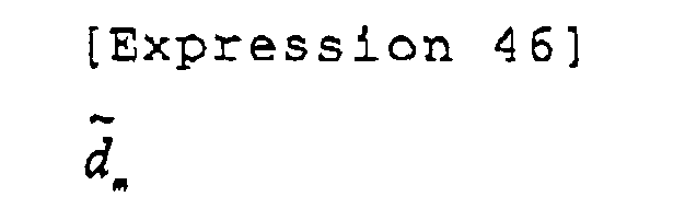
- Then, the received transmission, symbol sequences,
Expression 47, are multiplied by the spreading signal and the channel coefficients.
- In this way, the received signal sequences described by
Expression 48 for every reception path of the receiving antennas from the transmitting antennas are estimated according to Expression 49, and output.

- Fig. 4 is a block diagram of a multipath
receiving signal demodulator 50 that is a third embodiment of the multipath receiving signal demodulator. According to the third embodiment, the MLD algorithm is used, where the multipath receivingsignal demodulator 50 carries out the primary demodulation of the paths in one block. - As shown in Fig. 4, the multipath receiving
signal demodulator 50 includes a channelcoefficient estimating unit 51, NxLreverse spreading units 52 through 55, aQR factorizing unit 56, a QH operating unit 57, a transmission symbolcandidate generating unit 58, a conversion signalreplica generating unit 59, alikelihood calculating unit 60, M transmission symbol sequence estimating units 611 through 61m, and M multipath receiving signal demodulators 621 through 62m. - According to the multipath
receiving signal demodulator 50 of the third embodiment, the channelcoefficient estimating unit 51 receives the signals rn(t) received by the receiving antennas 211 through 21n, and the channel coefficients hm,n,ℓ of the paths between the receiving antennas 211 through 21n and the transmitting antennas 111 through 11n are estimated. - Next, the
reverse spreading units 52 through 55, which number NxL, perform reverse spreading of the received signals rn(t) with the same spreading signal as used at the time of transmission at the receiving timing of each path, and NxL reverse-spread signals zn,ℓ of the paths of the receiving antennas are obtained. - Next, the
QR factorizing unit 56 generates a channel matrix as shown byExpression 50, the channel matrix including channel coefficients expressed in NxL rows x M columns, performs QR factorization of the channel matrix, and a Q matrix and an R matrix are output.
(Example where M = 4, N = 4, L = 2)
H = QR - The Q matrix output from the
QR factorizing unit 56 is a unitary matrix having (NxL) rows x M columns, and suffices for QHQ=I. - Here, H expresses conjugate complex transposition, and "I" expresses a unit matrix. Further, the R matrix turns into an upper triangular matrix having M rows x M columns.
- The QH operating unit 57 performs operations according to the following expression.


- The transmission symbol
candidate generating unit 58 generates the transmission symbols dM,i for the M transmitting antennas 11, and outputs them to the conversion signalreplica generating unit 59. The conversion signalreplica generating unit 59 receives
the transmission symbols generated by the transmission symbolcandidate generating unit 58, and
the R matrix provided by theQR factorizing unit 56
for generating conversion signal replicas as described byExpression 52.
- The conversion signal replicas are generated according the following expression, and output.

- The
likelihood calculating unit 60 calculates errors using XM and x̂ M j (Expression 54) according toExpression 55.

- After performing the error calculations, the
likelihood calculating unit 60 receives the generated transmission symbol sequence corresponding to the transmitting antenna 11M, receives corresponding error signals, holds SM transmission symbols having smaller numbers of errors corresponding to the transmitting antenna 11M as described byExpression 56, and holds the corresponding errors as expressed byExpression 57.

- Then, the transmission symbol
candidate generating unit 58 generates a transmission symbol as described byExpression 58 for the transmitting antenna 11M-1, and outputs.
- The conversion signal
replica generating unit 59 receives
the R matrix,
the SM transmission symbol sequences corresponding to the transmitting antenna 11M, and
the transmission symbol corresponding to the transmitting antenna 11M-1
for generating conversion signal replicas as described byExpression 59 according toExpression 60, and outputs the conversion signal replicas.

- Subsequently, the
likelihood calculating unit 60 performs error calculations according to the following expression.
- The
likelihood calculating unit 60 holds SM-1 combinations of the transmission symbol sequences having smaller numbers of errors corresponding to the transmitting antenna 11M and the transmitting antenna 11M-1 as described by Expression 62.
- The
likelihood calculating unit 60 holds errors at that time as described by Expression 63.
- Similarly, the transmission symbol
candidate generating unit 58 generates and outputs the transmission symbols dm,i corresponding to the transmitting antenna 11m. The conversion signalreplica generating unit 59 receives
the R matrix,
the transmission symbol corresponding to the transmitting antenna 11m, and
Sm+1 transmission symbol sequences corresponding to the transmitting antennas from 11m+1 to 11M
for generating conversion signal replicas as described by Expression 64 according to Expression 65; and outputs the conversion signal replicas.

- The
likelihood calculating unit 60 performs error calculations according to the following expression.
- The
likelihood calculating unit 60 holds Sm combinations of the transmission symbol sequences corresponding to the transmitting antennas from 11m to 11M as described by Expression 67, the combinations having smaller numbers of errors.
- Further, the
likelihood calculating unit 60 holds the errors at that time as described by Expression 68.
- By repeating the operations described above, CxS2 combinations as described by Expression 69 of the transmission symbol sequences corresponding to all the transmitting antennas are obtained.

- Further by repeating the operations described above, the errors at that time as described by
Expression 70 are obtained.
- Here, j is an integer equal to 1 or greater up to CxS2.
- The transmission symbol sequence estimating units 611 through 61m receive surviving transmission symbols of the corresponding transmitting antennas, receive corresponding error signals, determine minimum errors, and estimate transmission symbol sequences that give the determined minimum errors.
- When the transmission symbol sequence estimating units 611 through 61m carry out hard decisions, they are performed as follows.

- When the transmission symbol sequence estimating units 61l through 61m carry out soft decisions, they are performed as follows.
- First, a bit sequence of soft decision is obtained according to the following expression.

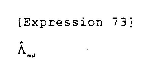

- Here, emin,v is the smallest of

where the i-th bit is "ν", and σ2 (n) is noise power. - The soft decision symbol

Expression 78, using Expression 77.

- Finally, the multipath receiving signal demodulators 621 through 62m receive the transmission symbol sequences that are estimated as described above, the transmission symbol sequences being described by
Expression 79.
- Then, the multipath receiving signal demodulators 621 through 62m multiply the received transmission symbol sequence as described by
Expression 80, the spreading signal, and the channel coefficients as shown byExpression 82 such that received signal sequences, as described byExpression 81, for every reception path between the transmitting antennas and the receiving antennas are estimated and output.


- According to the multipath
receiving signal demodulator 50, the number of times of error calculations is greatly reduced to
receiving signal demodulator 40 that is shown by Fig. 3, although some degradation in demodulating the received signal sequence has to be tolerated.
- Accordingly, complexity of the receiving apparatus is greatly reduced.
- Fig. 5 is a block diagram showing a multipath
receiving signal demodulator 70 that is a fourth embodiment of the multipath receiving signal demodulator. According to the fourth embodiment, the multipath receiving signal demodulator uses the MLD algorithm as the primary demodulation method, wherein each path is individually processed. - The multipath
receiving signal demodulator 70 includes a channelcoefficient estimating unit 71, NxLreverse spreading units 72 through 75, L sets ofQR factorizing units 76 and 77, L sets of QH operating units 78 and 79, a transmission symbolcandidate generating unit 80, a conversion signalreplica generating unit 81, alikelihood calculating unit 82, M transmission symbol sequence estimating units 831 through 83m, and M multipath receiving signal demodulators 84l through 84m. - According to the multipath
receiving signal demodulator 70 of the fourth embodiment, the channelcoefficient estimating unit 71 receives a signal rn(t) received by the N receiving antennas 211 through 21n, and estimates the channel coefficients hm,n,ℓ of each path between the receiving antennas 211 through 21n and the transmitting antennas 111 through 11m. - Next, the
reverse spreading units 72 through 75, which number NxL, perform reverse spreading of the received signal rn(t) with the same spreading signal as used at the time of transmission at the receiving timing of each path, and NxL reverse-spread signals zn,ℓ one for each path of the receiving antennas are obtained. - Next, an ℓ-th QR factorizing unit generates channel matrices that include channel coefficients of the ℓ-th path, the number of the channel matrices being equal to the number of the paths, and QR factorization of the channel matrices is performed such that a Q matrix and a R matrix are output.

- A Qℓ matrix output from the QR factorizing unit is a unitary matrix having N rows x M columns, and suffices for Q l HQ l =I. Further, a Rl matrix is an upper triangular matrix having M rows x M columns.
- Accordingly, an operation carried out by the ℓ-th QH operating unit can be described by Expression 85.

where M = 4, N = 4 - The transmission symbol
candidate generating unit 80 generates the transmission symbols dM,i corresponding to the transmitting antenna 11M, and outputs them to the conversion signalreplica generating unit 81. The conversion signalreplica generating unit 81 receives the transmission symbols dM,i, receives the Rℓ matrix, and generates conversion signal replicas as described by Expression 86 according to Expression 87, and output the conversion signal replicas.

- The
likelihood calculating unit 82 calculates errors according to Expression 89 using x̂M,i and x̂ Mjj (Expression 88).

- After performing the error calculation, the
likelihood calculating unit 82 receives the generated transmission symbol sequences corresponding to the transmitting antenna 11M, and the corresponding error signals. Then, thelikelihood calculating unit 82 holds SM transmission symbols as described by Expression 90 having smaller numbers of errors corresponding to the transmitting antenna 11M.
- Further, the
likelihood calculating unit 82 holds errors at that time as described by Expression 91.
- Next, the transmission symbol
candidate generating unit 80 generates a transmission symbol as described by Expression 92 corresponding to the transmitting antenna 11M-1 and outputs the transmission symbol.
- The conversion signal
replica generating unit 81 receives
the R matrix,
the SM transmission symbol sequences corresponding to the transmitting antenna 11M, and
the transmission symbol corresponding to the transmitting antenna 11M-l for generating conversion signal replicas as described by Expression 93, according to Expression 94, and outputs the conversion signal replicas.

- Subsequently, the
likelihood calculating unit 82 performs error calculations by the following expression.
- Then, the likelihood calculating unit B2 holds Sm-l combinations as described by Expression 96 of the transmission symbol sequences corresponding to the transmitting antenna 11M and the transmitting antenna 11M-1, the combinations having smaller numbers of errors.


- Further, the
likelihood calculating unit 82 holds the errors at that time as described by Expression 97.
- Similarly, the transmission symbol
candidate generating unit 80 generates and outputs the transmission symbols dm,i to the transmitting antenna 11m. The conversion signalreplica generating unit 81 receives
the R matrix,
the transmission symbol corresponding to the transmitting antenna 11m, and
Sm+1 transmission symbol sequences corresponding to the transmitting antennas from 11m+1 to 11M. - Then, the conversion signal
replica generating unit 81 generates conversion signal replicas as described by Expression 98 according to Expression 99.

- The
likelihood calculating unit 82 performs error calculations according to the following expression.
- The
likelihood calculating unit 82 holds Sm combinations as described byFormula 101 of the transmission symbol sequences corresponding to the transmitting antennas from 11m to 11M, the combinations having smaller numbers of errors.
- Further, the
likelihood calculating unit 82 holds the errors at that time as described byExpression 102.
- By repeating the calculations described above, CxS2 combinations as described by
Expression 103 of the transmission symbol sequences corresponding to all the transmitting antennas are obtained.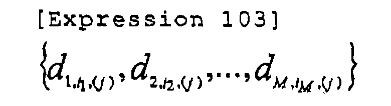
- Further, by repeating the calculations described above, the errors at that time as described by Expressing 104 are obtained.

where j is an integer equal to or greater than 1 up to CxS2. - The transmission symbol sequence estimating units 831 through 83m receive surviving transmission symbols and the corresponding error signals corresponding to each transmitting antenna, determine minimum errors, and estimate transmission symbol sequences that give the minimum errors.
- When the transmission symbol sequence estimating units 831 through 83m carry out hard decisions, they are made as follows.

- When the transmission symbol sequence estimating units 831 through 83m carry out soft decisions, they are made as follows. First, a bit sequence of soft decision is obtained according to the following expression.

- Here,


where emin,ν is the minimum of Expression 109,
- The soft decision symbol as described by Expression 110 is estimated as described by
Expression 112 usingExpression 111.


- Finally, the multipath receiving signal demodulators 841 through 84m receive the transmission symbol sequences as described by
Expression 113, the transmission symbol sequences being estimated as described above.
- The transmission symbol sequences as described by
Expression 114 are multiplied by the spreading signal and the channel coefficients so that received signal sequences as described by Expression 115 are obtained for every reception path from each transmitting antenna to every receiving antenna are obtained as described by Expression 116, and the received signal sequences are output.


- According to the multipath
receiving signal demodulator 70, similar to the case with the multipathreceiving signal modulator 50 shown by Fig, 4, the number of times of error calculations is greatly reduced to
receiving signal demodulator 40 that is shown by Fig. 3, although some degradation in demodulating the received signal sequence has to be tolerated.
- Fig. 6 is a block diagram of the channel coefficient estimating unit according to an embodiment of the present invention. Figs. 7A and 7B show frame structure examples of the signal transmitted from the transmitting apparatus when the channel coefficient estimating unit is used.
- First, the signal transmitted from the transmitting apparatus is described referring to Figs. 7A and 7B. According to the present embodiment, pilot symbols (indicated by hashed lines), each being 4 symbols long, and each being different, are periodically inserted into data symbols of the signals transmitted from the transmitting antennas (e.g., transmitting
antennas 1 and 2). In the example shown by Fig. 7A, pilot symbol patterns for the transmitting antennas are orthogonally arranged. - Further, in the example shown by Fig. 7B, spreading signals (C1, C2) used for spreading the pilot symbols for the transmitting antennas are orthogonally arranged.
- By orthogonally arranging the pilot signals between the transmitting antennas using one of the methods shown by Figs. 7A and 73, highly accurate channel estimation is attained. The orthogonal symbol patterns and the orthogonal spreading signals can be generated by using a Walsh sequence of the same length, for example, as the number of the pilot symbols, and the same length as the spreading signals for the pilot symbols. In the following description, a pilot signal sequence of a transmitting antenna m is expressed by pm(n), where n is a chip number.
- With reference to Fig. 6, the configuration of a channel
coefficient estimating unit 100 according to the present embodiment is described. The channelcoefficient estimating unit 100 is for estimating a channel coefficient of each path between the transmitting antenna m and a receiving antenna n. Here, an example is shown wherein the channelcoefficient estimating unit 100 is for 3 transmitting antennas and 4 receiving antennas. That is, the channelcoefficient estimating unit 100 includes 3x4correlation detecting units 101 through 104, and pilot signalreplica generating units 111 through 114. In addition, in this example, each of the correlation detecting units and the pilot signal replica generating units includes two or more components, which may be identified by a suffixed serial number when necessary. - First, operations of estimating a channel coefficient hl,l,l between the transmitting
antenna 1 and the receivingantenna 1 are described with reference to Fig. 6. - A signal rl is received by the receiving
antenna 1, and is provided to thecorrelation detecting unit 101. Further, the pilot signalreplica generating unit 111 generates a pilot symbol sequence pl corresponding to the transmittingantenna 1, which pl is provided to thecorrelation detecting unit 101. - The
correlation detecting unit 101 estimates the channel coefficient h1,1,1 between the transmittingantenna 1 and the receivingantenna 1 according to Expression 118, wherein
the received signal r1 is multiplied by a complex-conjugate value of the pilot symbol sequence pl of the transmittingantenna 1 in consideration of the receiving timing of a path ℓ, and
the obtained product is averaged over the 4 pilot symbol periods.
- Here, r1(n) represents the received signal r1 when a pilot symbol n is received. An implementation is possible wherein h1,1,1 is estimated by weight-averaging channel coefficients obtained in two or more pilot symbol periods.
- Similarly, a second step
correlation detecting unit 102 receives the signal r1, and a pilot symbol sequence p3 of the transmitting antenna 3 generated by a second step pilot symbolreplica generating unit 112, and a channel coefficient h1,3,ℓ is estimated and output. - Further, a received signal r4 and the pilot symbol sequence p1 of the transmitting
antenna 1 generated by the pilot symbolreplica generating unit 113 are provided to thecorrelation detecting unit 103, and correlation is obtained such that a channel coefficient h4,1,1 is estimated and output. - By repeating the above operation, the channel coefficient of all the paths between the 3 transmitting antenna and the 4 receiving antennas are estimated. According to the example described above, the pilot symbol is multiplexed by the data symbol in the time domain; nevertheless, the channel coefficient estimation can be obtained by the same method in the case where code multiplexing is employed.
- Fig. 8 is a block diagram of a receiving
apparatus 200 that is a second embodiment of the receiving apparatus of the present invention. As shown in Fig. 8, the receivingapparatus 200 includes multipath receivingsignal demodulators 211 through 213 that are serially connected through multipath interference canceling units 2211, 2212, 2221, 2222, 2231, and 2232 (i.e., this example is a 3-stage configuration), and ademodulator 231 that is arranged at the last stage. To the multipathreceiving signal demodulator 211, serving as the first stage, any one of the multipath receiving signal demodulators described with reference to Figs. 2 through 5 can be applied. - Further, any one of the multipath receiving signal demodulators described with reference to Figs. 2 through 5 can be applied to the multipath
receiving signal demodulators 
- This can be described as Expression 121, using the received signals, and output signals (Expression 120) of the (p-1)-th multipath receiving signal demodulator.
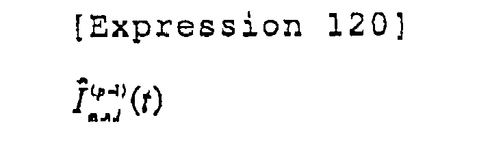
- Specifically, the signals that are input to the p-th multipath receiving signal demodulator are generated by the preceding multipath interference canceling units according to the following expression.

- NxL received signals after multipath interference cancellation obtained according to Expression 121 are described by Expression 122.

- The NxL received signals are provided to a reverse spreading unit (not illustrated) corresponding to the receiving antenna 21n and the path ℓ.
- Further, according to the configuration shown by Fig. 8, a channel coefficient estimating unit (not illustrated) of the p-th stage multipath receiving signal demodulator may use a received signal after multipath interference cancellation as described by Expression 123 instead of the received signal rn(t) when estimating the coefficient hl,l,l, which results in a more accurate channel coefficient estimation.

- (It is possible to use the channel coefficient of the (p-1)-th multipath receiving signal demodulator for simplification of the configuration.)
- As described above, by preparing two or more stages of the multipath receiving signal demodulators according to the present embodiment, the latter stage multipath receiving signal demodulators can use the received signal after multipath interference cancellation, which enables highly accurate channel estimation and transmission symbol sequence estimation. As a result, the received signal sequence as described by Expression 124 is accurately estimated for every reception path between the transmitting antennas and the receiving antennas.

- Fig. 9 is a block diagram of a
demodulator 300 that is a first embodiment of the demodulator applicable to the receiving apparatus according to the embodiments of the present invention, The present embodiment uses MLD for the demodulator as the demodulating algorithm. - The
demodulator 300 includes a channelcoefficient estimating unit 311, NxLreverse spreading units 312 through 315, a transmission symbolcandidate generating unit 316, received signalreplica generating unit 317, alikelihood calculating unit 318, and a transmittingsequence estimating unit 319. Where a certain unit includes two or more components, they are identified with a suffixed serial number. - An operation of the
demodulator 300 is described. - The
demodulator 300 is provided with NxL received signals after multipath interference cancellation as described by Expression 125.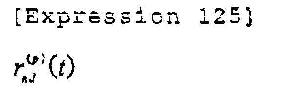
- The channel
coefficient estimating unit 311 estimates the channel coefficients hm,n,ℓ of each path between the receiving antennas and the transmitting antennas (here, it is also possible to use a channel coefficient of a preceding multipath receiving signal demodulator for simplification of the configuration). - Further, NxL received signals after multipath interference cancellation as described by Expression 126 are provided to a reverse spreading unit corresponding to a receiving antenna 21n and the path ℓ such that reverse-spread signals z'n,ℓ are obtained.
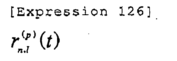
- The transmission symbol
candidate generating unit 316 generates and outputs the transmission symbols dm,i corresponding to each antenna. The received signalreplica generating unit 317 receives the transmission symbols and the channel coefficients, and generates received signal replicas as described by Expression 127 according to Expression 128, and outputs the received signal replicas to thelikelihood calculating unit 318.

- The
likelihood calculating unit 318 receives the reverse-spread signals z'n,l from thereverse spreading units 312 through 315, and the received signal replicas as described by Expression 129.
- Then, the
likelihood calculating unit 318 performs error calculations according to the following expression.
- The generated transmission symbols corresponding to each transmitting antenna, and the corresponding error signals are provided to the transmitting
sequence estimating unit 319 that outputs a likelihood λi of a bit transmitted by the transmission symbol sequence. Here, the bit likelihood based on the error signal may be calculated by any available method. - The bit likelihood described above is provided to a channel decoder (for example, a turbo decoder), etc., so that an information bit sequence is finally obtained.
- Fig. 10 is a block diagram of a
demodulator 400 that is a second embodiment of the demodulator of the present invention. The second embodiment uses MLD as the demodulating algorithm, wherein paths are grouped into a block for processing. - The
demodulator 400 includes a channelcoefficient estimating unit 411, NxLreverse spreading units 412 through 415, aQR factorizing unit 416, a QH operating unit 417, a transmission symbolcandidate generating unit 418, a conversion signalreplica generating unit 419, alikelihood calculating unit 420, and a transmittingsequence estimating unit 421. Where a certain unit includes two or more components, they are identified with a suffixed serial number, - Operations of the
demodulator 400 are described below. - The
demodulator 400 receives NxL signals as described by Expression 131 after multipath interference cancellation.
- The channel coefficients hm,n,ℓ of each path of between the receiving antennas and the transmitting antennas are estimated by the channel
coefficient estimating unit 411. (Here, it is also possible similarly to use a channel coefficient in a preceding multipath receiving signal demodulator for simplification of the configuration). - Furthermore, the NxL received signals after multipath interference cancellation

- Next, the
QR factorizing unit 416 generates the following channel matrix (Expression 133) containing channel coefficients, performs QR factorization of the channel matrix, and outputs a Q matrix and a R matrix to the QH operating unit 417.
H=QR - The Q matrix output from the
QR factorizing unit 417 is a unitary matrix having (NxL) rows x M columns, and suffices QHQ=I. Further, the R matrix is an upper triangular matrix having M rows x M columns. Accordingly, an operation carried out by the QH operating unit 417 can be described as follows.
- The transmission symbol
candidate generating unit 418 generates and outputs the transmission symbols dM,j corresponding to the transmitting antenna 11M. The conversion signalreplica generating unit 419 receives the transmission symbols dM,j and the R matrix. Then, the conversion signalreplica generating unit 419 generates conversion signal replicas as described by Expression 135 according to Expression 136, and outputs the conversion signal replicas to thelikelihood calculating unit 420.

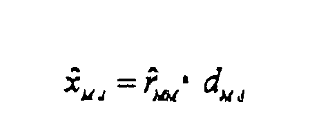
- The
likelihood calculating unit 420 calculates errors between x'M and x̂ M.j (Expression 137) according to Expression 138.

- The generated transmission symbol sequences corresponding to the transmitting antenna 11M and corresponding error signals are provided to the
likelihood calculating unit 420 for generating SM transmission symbols as described by Expression 139 having smaller numbers of errors corresponding to the transmitting antenna 11M.
- The
likelihood calculating unit 420 further calculates errors at that time as shown by Expression 140.
- The transmission symbol
candidate generating unit 418 generates the transmission symbols as described by Expression 141 corresponding to the transmitting antenna 11M-1, and outputs the transmission symbols.
- The conversion signal
replica generating unit 419 receives
the R matrix,
the SM transmission symbol sequences corresponding to the transmitting antenna 11M and,
the transmission symbols corresponding to the transmitting antenna 11M-1 for generating conversion signal replicas as described by Expression 142 using Expression 143, and the conversion signal replicas are output.

- Subsequently, the
likelihood calculating unit 420 performs error calculations according to the following expression.
- The
likelihood calculating unit 420 holds SM-1 combinations of the transmission symbol sequences corresponding the transmitting antenna 11M and the transmitting antenna 11M-1, the combinations having smaller numbers of errors.
- Further, the
likelihood calculating unit 420 holds the errors at that time as described by Expression 146.
- Similarly, the transmission symbol
candidate generating unit 418 generates and outputs the transmission symbols dm,i corresponding to the transmitting antenna 11m. The conversion signalreplica generating unit 419 receives
the Sm+1 transmission symbol sequences corresponding to the transmitting antennas from 11m+1 to 11M,
the transmission symbol corresponding to the transmitting antenna 11m, and
the R matrix for generating conversion signal replicas as described by Expression 147 according to Expression 148, and output the conversion signal replicas.

- The
likelihood calculating unit 420 performs error calculations according to the following expression.
- The
likelihood calculating unit 420 holds Sm combinations as described byExpression 150 of the transmission symbol sequences corresponding to the transmitting antennas from 11m to 11N, the combinations having smaller numbers of errors.
- Further, the
likelihood calculating unit 420 holds the errors at that time as described by Expression 151.

- By repeating the operations described above, CxS2 combinations of the transmission symbol sequences corresponding to all the transmitting antennas as described by Expression 152 are obtained.

- Further, the errors as described by Expression 153 at that time are obtained.
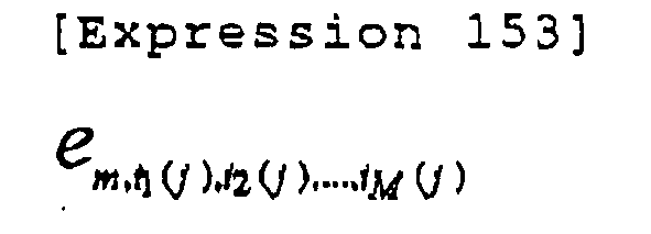
- The transmitting
sequence estimating unit 421 receives the surviving transmission symbols corresponding to each transmitting antenna and the corresponding error signals, and outputs a likelihood λi of a bit transmitted by the transmission symbol sequence, Here, the bit likelihood based on the error signal can be calculated using any available method. - The bit likelihood described is provided to a channel decoder (for example, a turbo decoder) etc., and an information bit sequence is finally obtained.
- According to the
demodulator 400, the number of times of error calculations is greatly reduced to
demodulator 300 that is shown by Fig. 9, although some degradation in the bit likelihood estimation has to be tolerated.
- In this way, the complexity of the receiving apparatus can be greatly decreased.
- Fig. 11 shows a
demodulator 500 that is a third embodiment of the demodulator of the present invention. According to thedemodulator 500 of the third embodiment, each path is processed by a demodulating algorithm that employs MLD. - The
demodulator 500 includes a channelcoefficient estimating unit 511, NxLreverse spreading units 512 through 515, LQR factorizing units candidate generating unit 520, a conversion signalreplica generating units 521, alikelihood calculating units 522, and a transmittingsequence estimating unit 523. Where a certain unit includes two or more components, they are identified with a suffixed serial number. - Operations of the
demodulator 500 are described below. - The
demodulator 500 receives NxL input signals that are the received signals after multipath interference cancellation as described by Expressed 155.
- The channel
coefficient estimating unit 511 estimates the channel coefficients hm,n,ℓ of each path between the receiving antennas and the transmitting antennas. (Here, it is possible to use a channel coefficient of a preceding multipath receiving signal demodulator for simplification of the configuration). - Furthermore, the NxL received signals after multipath interference cancellation as described by Expression 156 are provided to the reverse spreading unit corresponding to the receiving antenna 21n and the path ℓ so that the reverse-spread signals z'n,ℓ are obtained.

- Next, the ℓ-th QR factorizing unit generates the following channel matrix containing channel coefficients of the ℓ-th path for each path, performs QR factorization of the channel matrix so that the Q matrix and the R matrix are output.


- A Qℓ matrix output by the QR factorizing unit is a unitary matrix having N rows x M columns, and suffices Qℓ HQ ℓ =I. Here, H expresses a conjugate complex transposition, and "I" expresses a unit matrix. Further, a Rℓ matrix turns into an upper triangular matrix having M rows x M columns.
- Accordingly, the operation carried out by the ℓ-th QH operating unit can be described as follows.


- The transmission symbol
candidate generating unit 520 generates the transmission symbols dM,i corresponding to the transmitting antenna 11M, and outputs the transmission symbols dM,i to the conversion signalreplica generating unit 521. The conversion signalreplica generating unit 521 receives the transmission symbols dM,i and the Rℓ matrix so that the conversion signal replicas as described by Expression 159 are generated according to Expression 160, and output.

- The
likelihood calculating unit 522 performs error calculations using x'M,ℓ and the conversion signal replicas as described by Expression 161 according to Expression 162.

- After the error calculations, the
likelihood calculating unit 522 receives generated transmission symbol sequences corresponding to the transmitting antenna 11M, and the corresponding error signals. Thelikelihood calculating unit 522 holds SM transmission symbol sequences having smaller numbers of errors corresponding to the transmitting antenna 11M as described by Expression 163.
- Further, the
likelihood calculating unit 522 holds the errors at that time as described by Expression 164.
- Next, the transmission symbol
candidate generating unit 520 generates and outputs transmission symbols dM-l,i corresponding to the transmitting antenna 11M-l. - The conversion signal
replica generating unit 521 receives
the R matrix,
the SM transmission symbol sequences corresponding to the transmitting antenna 11M and
the transmission symbol corresponding to the transmitting antenna 11M-l for generating conversion signal replicas as described by Expression 165 according to Expression 166, and outputting the conversion signal replicas.

- Subsequently the
likelihood calculating unit 522 performs error calculations according to the following expression.
- The
likelihood calculating unit 522 holds SM-1 combinations as described by Expression 168 of the transmission symbol sequences corresponding the transmitting antenna 11M and the transmitting antenna 11M-1 having smaller numbers of errors.
- Further, the
likelihood calculating unit 522 holds the errors at that time as described by Expression 169.
- Similarly, the transmission symbol
candidate generating unit 520 generates and outputs the transmission symbols dm,i corresponding to the transmitting antenna 11m. The conversion signalreplica generating unit 521 receives
the R matrix,
Sm+1 transmission symbol sequences corresponding to the transmitting antennas m+1 to M, and
the transmission symbol corresponding to the transmitting antenna 11m for generating conversion signal replicas as described by Expression 170 according to Expression 171, and output.

- The
likelihood calculating unit 522 performs error calculations according to the following expression.
- The,
likelihood calculating unit 522 holds Sm combinations of the transmission symbol sequences corresponding to the transmitting antennas 11m to 11M having smaller numbers of errors as described by Expression 173.
- Further, the
likelihood calculating unit 522 holds the errors at that time as described by Expression 174.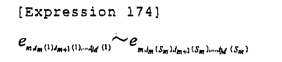
- By repeating the above operations, CxS2 combinations of the transmission symbol sequences corresponding to all the transmitting antennas, and the errors at that time are obtained as described by Expressions 175 and 176, respectively.


- The transmitting
sequence estimating unit 523 receives the surviving transmission symbols corresponding to each transmitting antenna obtained by the L likelihood calculating units, and the corresponding error signals; and outputs a likelihood λi transmitted by the transmission symbol sequence based on the sum of L error signals. Here, the bit likelihood based on the error signals can be calculated using any available method. - The bit likelihood described above is provided to a channel decoder (for example, turbo decoder), etc., and, the information bit sequence is finally obtained.
- According to the demodulator 500 (Fig. 11), the number of times of error calculations is greatly reduced to

demodulator 300 that is shown by Fig. 9, although some degradation in the bit likelihood estimation has to be tolerated.
- In this way, the complexity of the receiving apparatus is greatly reduced.
- Fig. 12 is a block diagram of a receiving
apparatus 600 that is a third embodiment of the receiving apparatus according to the present invention. The receivingapparatus 600 constitutes a radio communications system wherein a transmitting apparatus (not illustrated) performs serial parallel conversion of a transmitting data bit sequence into M transmitting sequences, which sequences are modulated with the same frequency and the same spreading code group, and are simultaneously transmitted by Ncode multicode channels from M transmitting antennas. - The receiving
apparatus 600 includes multipath receivingsignal demodulators 611 through 614 corresponding to each code channel (each ofcode channels demodulators interference canceling units 615 through 618. The multipathinterference canceling units 615 through 618 are inserted between one and another of the multipathreceiving signal demodulators 611 through 614, or between one of the multipathreceiving signal demodulators 611 through 614 and one of thedemodulators - According to the present embodiment, the multipath receiving
signal demodulators 
where k represents a code number that is limited by Expression 179.
- The multipath
interference canceling units 615 and 616 (note that N=2 in this example) receive the signals rn(t), and demodulated signal sequences of all the code channels as described by Expression 180 through correspondingadders 631 through 634.
- The multipath
interference canceling units 

- The multipath
receiving signal demodulators 
- The operations described are repeated for subsequent stages as applicable, and final received signals after multipath interference cancellation as described by Expression 184 are generated.

- The final received signals after multipath interference cancellation generated as above are provided to the
corresponding demodulators demodulators - Next, computer simulations of the embodiments of the present invention are described with reference to Fig. 13. Fig. 13 shows computer simulation results of throughput property (vertical axis) over average receiving Eb/No per receiving antenna (signal energy to the noise power density per 1 bit of information) (horizontal axis) of various demodulating methods used by the receiving apparatus; namely, the conventional MLD, the conventional 2-dimensional MMSE, and the method of the present invention.
- The receiving apparatus applied to the computer simulation includes two stages of the multipath receiving signal demodulators, where the configuration of Fig. 2 is used for the first stage, and the configuration of Fig. 4 is used for the second. Further, as for the multipath, a two-path model is used where both paths provide the same average received power.
- The spreading rate is 16, and 15 code channels are code-multiplexed (effective spreading rate is 15/16). In Fig. 13, a coding rate of channel coding using turbo coding is indicated by "R", solid lines represent properties according to the present invention (QR-MLD with two-stage MPIC), dotted lines represent properties of the conventional MMSE, and X marks represent properties of the conventional MLD. Further, • and ○ marks represent the average receiving Eb/No per receiving antenna in the case of MIMO multiplexing (4 transmitting antenna, 4 receiving antennas) using QPSK modulation; ■ and □ marks represent the average receiving Eb/No per receiving antenna in the case of MIMO multiplexing using 16QAM modulation.
- As shown by Fig. 13, average received power Eb/No required for obtaining a certain level of the throughput is greatly reduced by using the configuration of the receiving apparatus according to the embodiments of the present invention as compared with the case where the conventional signal separating method is used. That is, the receiving apparatus of the present invention requires less transmission power to obtain the same throughput as conventional apparatuses. In other words, the same transmitted power provides a greater throughput with the receiving apparatus according to the embodiments of the present invention.
- As described above, according to the present invention, when the MIMO multiplexing is used for simultaneous transmission of different data from two or more transmitting antennas in order to increase an information bit rate in a CDMA system, highly accurate signal separation is obtained, reducing-the multipath interference. Consequently, the receiving bit error rate and receiving packet error rate in a multipath fading environment are greatly reduced, and the throughput (information bit transmission rate that provides no errors) is greatly raised.
- Although the multipath receiving signal demodulator has been described as using algorithms (for example, a program that describes the algorithm) such as MMSE and MLD, other algorithms such as QR-MLD algorithm can be more desirable for obtaining accurate signal separation by a realistic amount of calculations.
- Further, although the receiving apparatus has been described as being used in a radio communications system, the receiving apparatus can be applied to a base station of a mobile communications system. Further, the algorithm of the present invention can be applied to a so-called software radio base station, to which the algorithm is selectively downloaded to a radio apparatus through a radio circuit or a wire circuit for changing properties of the radio apparatus.
- The present invention is applicable to a radio communications system that demodulates signals using two or more antennas.
- The present application is based on
Japanese Priority Application No. 2004-063197 filed on March 5, 2004
Claims (15)
- A receiving apparatus using a CDMA method for receiving signals by N receiving antennas (N is a positive integer), the signals being transmitted by M transmitting antennas (M is a positive integer), comprising:multipath receiving signal demodulating units for primary demodulation of the signals received by the receiving antennas, for estimating the signals transmitted from the transmitting antennas, and for obtaining a received signal of each path of the receiving antennas in a multipath environment based on the estimated signals;multipath interference canceling units for deducting the obtained signals received through the paths other than a target path from the signals received by the receiving antennas to obtain multipath interference cancelled signals; anda demodulating unit for secondary demodulation of the multipath interference cancelled signals.
- The receiving apparatus as claimed in claim 1, wherein
the multipath receiving signal demodulating units carry out the primary demodulation using a minimum mean square error (MMSE) method. - The receiving apparatus as claimed in claim 1, wherein
the multipath receiving signal demodulating units carry out the primary demodulation using a maximum likelihood detection (MLD) method. - The receiving apparatus as claimed in claim 1, wherein
the multipath receiving signal demodulating units carry out the primary demodulation using a maximum likelihood detection method using QR factorization on a block of a plurality of the paths. - The receiving apparatus as claimed in claim 1, wherein
the multipath receiving signal demodulating units carry out the primary demodulation using a maximum likelihood detection method using QR factorization on each of the paths. - The receiving apparatus as claimed in claim 2, wherein
the multipath receiving signal demodulating units control an amplitude of the signal received, based on a probability of correctness of a transmission symbol sequence estimated using the method as claimed in claim 2. - The receiving apparatus as claimed in claim 2, wherein
the multipath receiving signal demodulating units estimate a channel coefficient using a known pilot signal transmitted from the M transmitting antennas. - The receiving apparatus as claimed in claim 2, wherein
the multipath receiving signal demodulating units and the multipath interference canceling units are arranged in stages. - The receiving apparatus as claimed in claim 8, wherein
when the multipath receiving signal demodulating units are connected in the stages, each of the stages other than the first stage updates a channel coefficient estimated based on a known pilot signal transmitted from the M transmitting antennas using the multipath interference cancelled signal provided by the multipath interference canceling unit. - The receiving apparatus as claimed in claim 1, wherein
the demodulating unit performs the secondary demodulation using a maximum likelihood detection method. - The receiving apparatus as claimed in claim 1, wherein
the demodulating unit performs the secondary demodulation using a maximum likelihood detection method using QR factorization on a block of a plurality of the paths. - The receiving apparatus as claimed in claim 1, wherein
the demodulating unit performs the secondary demodulation using a maximum likelihood detection method using QR factorization on each of the paths. - The receiving apparatus as claimed in claim 1, wherein
when the signals transmitted from the M transmitting antennas are code-multiplexed signals,
the multipath receiving signal demodulating units perform the primary demodulation of the signals received by the corresponding receiving antennas, and obtain the signals of the corresponding paths for all the receiving antennas for all spreading signals,
the multipath interference canceling units deduct the obtained signals corresponding to all, the spreading signals received through the paths other than a target path from the signals received by the receiving antennas to obtain multipath interference cancelled signals, and
the demodulating unit performs the secondary demodulation of the multipath interference cancelled signals for each of the spreading signals. - A receiving method of a receiving apparatus for receiving a plurality of signals using a CDMA method, the signals being transmitted from M transmitting antennas (M is a positive integer) and received by N receiving antennas (N is a positive integer), comprising:a step of receiving the signal received by each of the receiving antennas, and estimating the signal transmitted from each of the transmitting antennas using a predetermined algorithm;a step of multiplying the estimated transmitted signal and a channel coefficient estimated based on a known pilot signal, and obtaining the received signal of each path for each of the receiving antennas in a multipath environment;a step of deducting the obtained received signals of the paths other than a target path from the signal received by each of the receiving antennas; anda step of demodulating the signals that are obtained by the step of deducting.
- A radio communications system, comprising:the receiving apparatus as claimed in claim 1; anda transmitting apparatus including the M transmitting antennas (M is a positive integer) for transmitting a CDMA signal from each of the transmitting antennas.
Applications Claiming Priority (2)
| Application Number | Priority Date | Filing Date | Title |
|---|---|---|---|
| JP2004063197 | 2004-03-05 | ||
| PCT/JP2005/003774 WO2005086402A1 (en) | 2004-03-05 | 2005-03-04 | Receiver apparatus, receiving method, and wireless communication system |
Publications (3)
| Publication Number | Publication Date |
|---|---|
| EP1722499A1 true EP1722499A1 (en) | 2006-11-15 |
| EP1722499A4 EP1722499A4 (en) | 2008-06-04 |
| EP1722499B1 EP1722499B1 (en) | 2011-02-16 |
Family
ID=34918146
Family Applications (1)
| Application Number | Title | Priority Date | Filing Date |
|---|---|---|---|
| EP20050720046 Expired - Lifetime EP1722499B1 (en) | 2004-03-05 | 2005-03-04 | Receiver apparatus, receiving method, and wireless communication system |
Country Status (8)
| Country | Link |
|---|---|
| US (1) | US7991360B2 (en) |
| EP (1) | EP1722499B1 (en) |
| JP (1) | JP4322918B2 (en) |
| CN (1) | CN1930813B (en) |
| AT (1) | ATE498948T1 (en) |
| DE (1) | DE602005026370D1 (en) |
| ES (1) | ES2361418T3 (en) |
| WO (1) | WO2005086402A1 (en) |
Families Citing this family (19)
| Publication number | Priority date | Publication date | Assignee | Title |
|---|---|---|---|---|
| MXPA05000828A (en) * | 2002-07-19 | 2005-04-19 | Interdigital Tech Corp | Groupwise successive interference cancellation for block transmission with reception diversity. |
| JP4478119B2 (en) * | 2005-05-25 | 2010-06-09 | パナソニック株式会社 | Receiver |
| JP4666150B2 (en) | 2005-05-31 | 2011-04-06 | 日本電気株式会社 | MIMO receiving apparatus, receiving method, and radio communication system |
| US8107549B2 (en) | 2005-11-30 | 2012-01-31 | Qualcomm, Incorporated | Multi-stage receiver for wireless communication |
| KR100706618B1 (en) * | 2005-12-09 | 2007-04-12 | 한국전자통신연구원 | Soft Decision Demapping Method Suitable for Higher-order Modulation for Iterative Decoder and Its Error Correction Device |
| JP2007300383A (en) * | 2006-04-28 | 2007-11-15 | Fujitsu Ltd | MIMO-OFDM transmitter |
| ES2774150T3 (en) * | 2006-11-06 | 2020-07-17 | Qualcomm Inc | MIMO detection with interference cancellation of timed signal components |
| US8315343B2 (en) * | 2007-12-17 | 2012-11-20 | Telefonaktiebolaget Lm Ericsson (Publ) | Multi-antenna receiver interference cancellation method and apparatus |
| JP2009272725A (en) * | 2008-04-30 | 2009-11-19 | Sharp Corp | Communication system, reception device, and communication method |
| JP5177527B2 (en) * | 2008-07-28 | 2013-04-03 | シャープ株式会社 | COMMUNICATION SYSTEM, RECEPTION DEVICE, AND COMMUNICATION METHOD |
| JP5431481B2 (en) * | 2008-08-20 | 2014-03-05 | クゥアルコム・インコーポレイテッド | Method and apparatus for signal allocation in a single channel |
| US8238488B1 (en) * | 2008-09-02 | 2012-08-07 | Marvell International Ltd. | Multi-stream maximum-likelihood demodulation based on bitwise constellation partitioning |
| JP5241437B2 (en) * | 2008-11-13 | 2013-07-17 | 三星電子株式会社 | Reception device and signal processing method |
| JP5375965B2 (en) * | 2009-01-21 | 2013-12-25 | 日本電気株式会社 | Demodulation method for MIMO system |
| CN103404066B (en) * | 2011-04-22 | 2016-05-25 | 三菱电机株式会社 | Communication device using multiple communication paths |
| JP5803429B2 (en) | 2011-08-25 | 2015-11-04 | 富士通株式会社 | Receiver |
| US9876595B2 (en) * | 2012-02-06 | 2018-01-23 | Maxlinear, Inc. | Method and system for a distributed receiver |
| US9722730B1 (en) | 2015-02-12 | 2017-08-01 | Marvell International Ltd. | Multi-stream demodulation schemes with progressive optimization |
| CN111615844B (en) * | 2018-01-08 | 2022-04-19 | 瑞典爱立信有限公司 | Method and apparatus for selecting a session management entity serving a wireless communication device |
Family Cites Families (13)
| Publication number | Priority date | Publication date | Assignee | Title |
|---|---|---|---|---|
| US5506861A (en) * | 1993-11-22 | 1996-04-09 | Ericsson Ge Mobile Comminications Inc. | System and method for joint demodulation of CDMA signals |
| US5887034A (en) * | 1996-03-29 | 1999-03-23 | Nec Corporation | DS-CDMA multiple user serial interference canceler unit and method of transmitting interference replica signal of the same |
| SG84514A1 (en) * | 1998-08-31 | 2001-11-20 | Oki Techno Ct Singapore Pte | Receiving device and channel estimator for use in a cdma communication system |
| JP3515033B2 (en) * | 2000-01-19 | 2004-04-05 | 松下電器産業株式会社 | Interference signal removal apparatus and interference signal removal method |
| GB0016663D0 (en) * | 2000-07-06 | 2000-08-23 | Nokia Networks Oy | Receiver and method of receiving |
| JP3714910B2 (en) * | 2001-02-20 | 2005-11-09 | 株式会社エヌ・ティ・ティ・ドコモ | Turbo receiving method and receiver thereof |
| US7181167B2 (en) * | 2001-11-21 | 2007-02-20 | Texas Instruments Incorporated | High data rate closed loop MIMO scheme combining transmit diversity and data multiplexing |
| JP3829108B2 (en) | 2002-07-26 | 2006-10-04 | ホシデン株式会社 | Card connector |
| US7075972B2 (en) * | 2002-08-19 | 2006-07-11 | Mitsubishi Electric Research Laboratories, Inc. | Intra-cell interference cancellation in a W-CDMA communications network |
| JP3960888B2 (en) * | 2002-09-03 | 2007-08-15 | 株式会社エヌ・ティ・ティ・ドコモ | Signal separation method and receiving apparatus |
| US8320301B2 (en) * | 2002-10-25 | 2012-11-27 | Qualcomm Incorporated | MIMO WLAN system |
| KR100470401B1 (en) * | 2002-12-24 | 2005-02-05 | 한국전자통신연구원 | A wireless communication system and method using grouping Maximum Lilelihood Detection |
| US8036325B2 (en) * | 2006-03-09 | 2011-10-11 | Interdigital Technology Corporation | Wireless communication method and apparatus for performing knowledge-based and blind interference cancellation |
-
2005
- 2005-03-04 US US10/591,663 patent/US7991360B2/en not_active Expired - Fee Related
- 2005-03-04 CN CN2005800071148A patent/CN1930813B/en not_active Expired - Fee Related
- 2005-03-04 WO PCT/JP2005/003774 patent/WO2005086402A1/en not_active Ceased
- 2005-03-04 AT AT05720046T patent/ATE498948T1/en not_active IP Right Cessation
- 2005-03-04 EP EP20050720046 patent/EP1722499B1/en not_active Expired - Lifetime
- 2005-03-04 DE DE200560026370 patent/DE602005026370D1/en not_active Expired - Lifetime
- 2005-03-04 JP JP2006510745A patent/JP4322918B2/en not_active Expired - Fee Related
- 2005-03-04 ES ES05720046T patent/ES2361418T3/en not_active Expired - Lifetime
Non-Patent Citations (4)
| Title |
|---|
| KALEONG LO ET AL: "Layered space time coding with joint iterative detection, channel estimation and decoding" SPREAD SPECTRUM TECHNIQUES AND APPLICATIONS, 2002 IEEE SEVENTH INTERNATIONAL SYMPOSIUM ON SEPT. 2-5, 2002, PISCATAWAY, NJ, USA,IEEE, vol. 2, 2 September 2002 (2002-09-02), pages 308-312, XP010615481 ISBN: 0-7803-7627-7 * |
| PETRI F ET AL: "Combined space-time chip equalization and parallel interference cancellation for DS-CDMA downlink with spatial multiplexing" PERSONAL, INDOOR AND MOBILE RADIO COMMUNICATIONS, 2002. THE 13TH IEEE INTERNATIONAL SYMPOSIUM ON SEPT. 15-18, 2002, PISCATAWAY, NJ, USA,IEEE, vol. 3, 15 September 2002 (2002-09-15), pages 1117-1121, XP010611436 ISBN: 0-7803-7589-0 * |
| See also references of WO2005086402A1 * |
| YUMIN ZHANG ET AL: "Multistage multiuser detection for CDMA with space-time coding" STATISTICAL SIGNAL AND ARRAY PROCESSING, 2000. PROCEEDINGS OF THE TENTH IEEE WORKSHOP ON AUGUST 14-16, 2000, PISCATAWAY, NJ, USA,IEEE, 14 August 2000 (2000-08-14), pages 1-4, XP010512110 ISBN: 0-7803-5988-7 * |
Also Published As
| Publication number | Publication date |
|---|---|
| CN1930813B (en) | 2010-05-05 |
| JPWO2005086402A1 (en) | 2008-01-24 |
| CN1930813A (en) | 2007-03-14 |
| JP4322918B2 (en) | 2009-09-02 |
| EP1722499B1 (en) | 2011-02-16 |
| ATE498948T1 (en) | 2011-03-15 |
| US20070197166A1 (en) | 2007-08-23 |
| DE602005026370D1 (en) | 2011-03-31 |
| EP1722499A4 (en) | 2008-06-04 |
| US7991360B2 (en) | 2011-08-02 |
| ES2361418T3 (en) | 2011-06-16 |
| WO2005086402A1 (en) | 2005-09-15 |
Similar Documents
| Publication | Publication Date | Title |
|---|---|---|
| US7991360B2 (en) | Receiver apparatus, receiving method, and wireless communication system | |
| CN101449502B (en) | Radio communication device and radio communication method | |
| US7656936B2 (en) | Method and system for interference reduction in a wireless communication network using a joint detector | |
| US7266355B2 (en) | Low complexity equalizer for radio receiver | |
| CN100403596C (en) | Efficient Multiple-Input Multiple-Output System for Multipath Fading Channels | |
| US8150326B2 (en) | Signal processing for multi-sectored wireless communications system and method thereof | |
| EP1779537B1 (en) | Reduced complexity soft value generation for mimo jd-grake receivers | |
| EP2104981B1 (en) | Antenna selection and soft demapping for mimo decoding | |
| JP4666150B2 (en) | MIMO receiving apparatus, receiving method, and radio communication system | |
| RU2484582C2 (en) | Method and apparatus for successive interference subtraction with covariance root processing | |
| EP1233565B1 (en) | Turbo-reception method and turbo-receiver for a MIMO system | |
| JP5146920B2 (en) | Receiving apparatus and mobile communication system | |
| US6901122B2 (en) | Method and apparatus for restoring a soft decision component of a signal | |
| US20070223411A1 (en) | Iterative multi-stage detection technique for a diversity receiver having multiple antenna elements | |
| CN101278500A (en) | Wireless communication device | |
| JP2006025453A (en) | Method of recovering data in code division multiple access communication system | |
| EP3048766A1 (en) | Double iterative MIMO receiver | |
| JP2006067070A (en) | MIMO system receiving method and apparatus thereof | |
| EP1727297A1 (en) | Method and Terminal for reducing interference in a radio communication system | |
| CN1613202A (en) | Strong and Low Complexity Multi-Antenna Adaptive Minimum Mean Square Error Equalizer | |
| KR100703263B1 (en) | Apparatus and method for removing interference signal in mobile communication system using multiple antennas | |
| WO2007114478A1 (en) | Receiver | |
| KR100789355B1 (en) | Receiver, Receiving Method, and Wireless Communication System | |
| JP4549162B2 (en) | Radio base station apparatus and radio communication method | |
| CN101355378B (en) | Symbol Demapping Method and Device for Multiple Input and Output Communication System |
Legal Events
| Date | Code | Title | Description |
|---|---|---|---|
| PUAI | Public reference made under article 153(3) epc to a published international application that has entered the european phase |
Free format text: ORIGINAL CODE: 0009012 |
|
| 17P | Request for examination filed |
Effective date: 20060904 |
|
| AK | Designated contracting states |
Kind code of ref document: A1 Designated state(s): AT BE BG CH CY CZ DE DK EE ES FI FR GB GR HU IE IS IT LI LT LU MC NL PL PT RO SE SI SK TR |
|
| DAX | Request for extension of the european patent (deleted) | ||
| A4 | Supplementary search report drawn up and despatched |
Effective date: 20080508 |
|
| RIC1 | Information provided on ipc code assigned before grant |
Ipc: H04J 13/04 20060101ALI20080430BHEP Ipc: H04B 1/707 20060101AFI20080430BHEP Ipc: H04J 15/00 20060101ALI20080430BHEP Ipc: H04B 1/10 20060101ALI20080430BHEP Ipc: H04B 7/26 20060101ALI20080430BHEP |
|
| 17Q | First examination report despatched |
Effective date: 20080708 |
|
| RIC1 | Information provided on ipc code assigned before grant |
Ipc: H04B 7/26 20060101ALI20100427BHEP Ipc: H04B 1/707 20060101AFI20100427BHEP Ipc: H04J 13/04 20060101ALI20100427BHEP Ipc: H04B 1/10 20060101ALI20100427BHEP |
|
| GRAP | Despatch of communication of intention to grant a patent |
Free format text: ORIGINAL CODE: EPIDOSNIGR1 |
|
| GRAS | Grant fee paid |
Free format text: ORIGINAL CODE: EPIDOSNIGR3 |
|
| GRAA | (expected) grant |
Free format text: ORIGINAL CODE: 0009210 |
|
| AK | Designated contracting states |
Kind code of ref document: B1 Designated state(s): AT BE BG CH CY CZ DE DK EE ES FI FR GB GR HU IE IS IT LI LT LU MC NL PL PT RO SE SI SK TR |
|
| REG | Reference to a national code |
Ref country code: GB Ref legal event code: FG4D |
|
| REG | Reference to a national code |
Ref country code: CH Ref legal event code: EP |
|
| REG | Reference to a national code |
Ref country code: IE Ref legal event code: FG4D |
|
| REF | Corresponds to: |
Ref document number: 602005026370 Country of ref document: DE Date of ref document: 20110331 Kind code of ref document: P |
|
| REG | Reference to a national code |
Ref country code: DE Ref legal event code: R096 Ref document number: 602005026370 Country of ref document: DE Effective date: 20110331 |
|
| REG | Reference to a national code |
Ref country code: SE Ref legal event code: TRGR |
|
| REG | Reference to a national code |
Ref country code: NL Ref legal event code: VDEP Effective date: 20110216 |
|
| REG | Reference to a national code |
Ref country code: ES Ref legal event code: FG2A Ref document number: 2361418 Country of ref document: ES Kind code of ref document: T3 Effective date: 20110616 |
|
| LTIE | Lt: invalidation of european patent or patent extension |
Effective date: 20110216 |
|
| PG25 | Lapsed in a contracting state [announced via postgrant information from national office to epo] |
Ref country code: LT Free format text: LAPSE BECAUSE OF FAILURE TO SUBMIT A TRANSLATION OF THE DESCRIPTION OR TO PAY THE FEE WITHIN THE PRESCRIBED TIME-LIMIT Effective date: 20110216 Ref country code: GR Free format text: LAPSE BECAUSE OF FAILURE TO SUBMIT A TRANSLATION OF THE DESCRIPTION OR TO PAY THE FEE WITHIN THE PRESCRIBED TIME-LIMIT Effective date: 20110517 Ref country code: PT Free format text: LAPSE BECAUSE OF FAILURE TO SUBMIT A TRANSLATION OF THE DESCRIPTION OR TO PAY THE FEE WITHIN THE PRESCRIBED TIME-LIMIT Effective date: 20110616 |
|
| PG25 | Lapsed in a contracting state [announced via postgrant information from national office to epo] |
Ref country code: BE Free format text: LAPSE BECAUSE OF FAILURE TO SUBMIT A TRANSLATION OF THE DESCRIPTION OR TO PAY THE FEE WITHIN THE PRESCRIBED TIME-LIMIT Effective date: 20110216 Ref country code: NL Free format text: LAPSE BECAUSE OF FAILURE TO SUBMIT A TRANSLATION OF THE DESCRIPTION OR TO PAY THE FEE WITHIN THE PRESCRIBED TIME-LIMIT Effective date: 20110216 Ref country code: AT Free format text: LAPSE BECAUSE OF FAILURE TO SUBMIT A TRANSLATION OF THE DESCRIPTION OR TO PAY THE FEE WITHIN THE PRESCRIBED TIME-LIMIT Effective date: 20110216 Ref country code: BG Free format text: LAPSE BECAUSE OF FAILURE TO SUBMIT A TRANSLATION OF THE DESCRIPTION OR TO PAY THE FEE WITHIN THE PRESCRIBED TIME-LIMIT Effective date: 20110516 Ref country code: SI Free format text: LAPSE BECAUSE OF FAILURE TO SUBMIT A TRANSLATION OF THE DESCRIPTION OR TO PAY THE FEE WITHIN THE PRESCRIBED TIME-LIMIT Effective date: 20110216 Ref country code: PL Free format text: LAPSE BECAUSE OF FAILURE TO SUBMIT A TRANSLATION OF THE DESCRIPTION OR TO PAY THE FEE WITHIN THE PRESCRIBED TIME-LIMIT Effective date: 20110216 Ref country code: CY Free format text: LAPSE BECAUSE OF FAILURE TO SUBMIT A TRANSLATION OF THE DESCRIPTION OR TO PAY THE FEE WITHIN THE PRESCRIBED TIME-LIMIT Effective date: 20110216 |
|
| PG25 | Lapsed in a contracting state [announced via postgrant information from national office to epo] |
Ref country code: DK Free format text: LAPSE BECAUSE OF FAILURE TO SUBMIT A TRANSLATION OF THE DESCRIPTION OR TO PAY THE FEE WITHIN THE PRESCRIBED TIME-LIMIT Effective date: 20110216 Ref country code: EE Free format text: LAPSE BECAUSE OF FAILURE TO SUBMIT A TRANSLATION OF THE DESCRIPTION OR TO PAY THE FEE WITHIN THE PRESCRIBED TIME-LIMIT Effective date: 20110216 Ref country code: MC Free format text: LAPSE BECAUSE OF NON-PAYMENT OF DUE FEES Effective date: 20110331 |
|
| REG | Reference to a national code |
Ref country code: CH Ref legal event code: PL |
|
| PG25 | Lapsed in a contracting state [announced via postgrant information from national office to epo] |
Ref country code: CZ Free format text: LAPSE BECAUSE OF FAILURE TO SUBMIT A TRANSLATION OF THE DESCRIPTION OR TO PAY THE FEE WITHIN THE PRESCRIBED TIME-LIMIT Effective date: 20110216 Ref country code: SK Free format text: LAPSE BECAUSE OF FAILURE TO SUBMIT A TRANSLATION OF THE DESCRIPTION OR TO PAY THE FEE WITHIN THE PRESCRIBED TIME-LIMIT Effective date: 20110216 Ref country code: RO Free format text: LAPSE BECAUSE OF FAILURE TO SUBMIT A TRANSLATION OF THE DESCRIPTION OR TO PAY THE FEE WITHIN THE PRESCRIBED TIME-LIMIT Effective date: 20110216 |
|
| PLBE | No opposition filed within time limit |
Free format text: ORIGINAL CODE: 0009261 |
|
| STAA | Information on the status of an ep patent application or granted ep patent |
Free format text: STATUS: NO OPPOSITION FILED WITHIN TIME LIMIT |
|
| REG | Reference to a national code |
Ref country code: IE Ref legal event code: MM4A |
|
| 26N | No opposition filed |
Effective date: 20111117 |
|
| PG25 | Lapsed in a contracting state [announced via postgrant information from national office to epo] |
Ref country code: CH Free format text: LAPSE BECAUSE OF NON-PAYMENT OF DUE FEES Effective date: 20110331 Ref country code: IE Free format text: LAPSE BECAUSE OF NON-PAYMENT OF DUE FEES Effective date: 20110304 Ref country code: LI Free format text: LAPSE BECAUSE OF NON-PAYMENT OF DUE FEES Effective date: 20110331 |
|
| REG | Reference to a national code |
Ref country code: DE Ref legal event code: R097 Ref document number: 602005026370 Country of ref document: DE Effective date: 20111117 |
|
| PG25 | Lapsed in a contracting state [announced via postgrant information from national office to epo] |
Ref country code: LU Free format text: LAPSE BECAUSE OF NON-PAYMENT OF DUE FEES Effective date: 20110304 |
|
| PG25 | Lapsed in a contracting state [announced via postgrant information from national office to epo] |
Ref country code: IS Free format text: LAPSE BECAUSE OF FAILURE TO SUBMIT A TRANSLATION OF THE DESCRIPTION OR TO PAY THE FEE WITHIN THE PRESCRIBED TIME-LIMIT Effective date: 20110216 |
|
| PG25 | Lapsed in a contracting state [announced via postgrant information from national office to epo] |
Ref country code: TR Free format text: LAPSE BECAUSE OF FAILURE TO SUBMIT A TRANSLATION OF THE DESCRIPTION OR TO PAY THE FEE WITHIN THE PRESCRIBED TIME-LIMIT Effective date: 20110216 |
|
| PG25 | Lapsed in a contracting state [announced via postgrant information from national office to epo] |
Ref country code: HU Free format text: LAPSE BECAUSE OF FAILURE TO SUBMIT A TRANSLATION OF THE DESCRIPTION OR TO PAY THE FEE WITHIN THE PRESCRIBED TIME-LIMIT Effective date: 20110216 |
|
| PGFP | Annual fee paid to national office [announced via postgrant information from national office to epo] |
Ref country code: FI Payment date: 20140311 Year of fee payment: 10 Ref country code: SE Payment date: 20140311 Year of fee payment: 10 |
|
| PGFP | Annual fee paid to national office [announced via postgrant information from national office to epo] |
Ref country code: FR Payment date: 20140311 Year of fee payment: 10 Ref country code: IT Payment date: 20140306 Year of fee payment: 10 Ref country code: ES Payment date: 20140211 Year of fee payment: 10 |
|
| PGFP | Annual fee paid to national office [announced via postgrant information from national office to epo] |
Ref country code: GB Payment date: 20140226 Year of fee payment: 10 |
|
| PGFP | Annual fee paid to national office [announced via postgrant information from national office to epo] |
Ref country code: DE Payment date: 20140417 Year of fee payment: 10 |
|
| REG | Reference to a national code |
Ref country code: DE Ref legal event code: R119 Ref document number: 602005026370 Country of ref document: DE |
|
| PG25 | Lapsed in a contracting state [announced via postgrant information from national office to epo] |
Ref country code: FI Free format text: LAPSE BECAUSE OF NON-PAYMENT OF DUE FEES Effective date: 20150304 |
|
| GBPC | Gb: european patent ceased through non-payment of renewal fee |
Effective date: 20150304 |
|
| PG25 | Lapsed in a contracting state [announced via postgrant information from national office to epo] |
Ref country code: SE Free format text: LAPSE BECAUSE OF NON-PAYMENT OF DUE FEES Effective date: 20150305 |
|
| REG | Reference to a national code |
Ref country code: SE Ref legal event code: EUG |
|
| PG25 | Lapsed in a contracting state [announced via postgrant information from national office to epo] |
Ref country code: IT Free format text: LAPSE BECAUSE OF NON-PAYMENT OF DUE FEES Effective date: 20150304 |
|
| REG | Reference to a national code |
Ref country code: FR Ref legal event code: ST Effective date: 20151130 |
|
| PG25 | Lapsed in a contracting state [announced via postgrant information from national office to epo] |
Ref country code: GB Free format text: LAPSE BECAUSE OF NON-PAYMENT OF DUE FEES Effective date: 20150304 Ref country code: DE Free format text: LAPSE BECAUSE OF NON-PAYMENT OF DUE FEES Effective date: 20151001 |
|
| PG25 | Lapsed in a contracting state [announced via postgrant information from national office to epo] |
Ref country code: FR Free format text: LAPSE BECAUSE OF NON-PAYMENT OF DUE FEES Effective date: 20150331 |
|
| REG | Reference to a national code |
Ref country code: ES Ref legal event code: FD2A Effective date: 20160527 |
|
| PG25 | Lapsed in a contracting state [announced via postgrant information from national office to epo] |
Ref country code: ES Free format text: LAPSE BECAUSE OF NON-PAYMENT OF DUE FEES Effective date: 20150305 |