EP1722280A2 - Printer contaminant abatement systems and methods - Google Patents
Printer contaminant abatement systems and methods Download PDFInfo
- Publication number
- EP1722280A2 EP1722280A2 EP06113670A EP06113670A EP1722280A2 EP 1722280 A2 EP1722280 A2 EP 1722280A2 EP 06113670 A EP06113670 A EP 06113670A EP 06113670 A EP06113670 A EP 06113670A EP 1722280 A2 EP1722280 A2 EP 1722280A2
- Authority
- EP
- European Patent Office
- Prior art keywords
- manifold
- vacuum
- blower
- air duct
- bearing member
- Prior art date
- Legal status (The legal status is an assumption and is not a legal conclusion. Google has not performed a legal analysis and makes no representation as to the accuracy of the status listed.)
- Granted
Links
- 239000000356 contaminant Substances 0.000 title description 9
- 238000000034 method Methods 0.000 title description 3
- 238000007639 printing Methods 0.000 claims abstract description 20
- 239000002245 particle Substances 0.000 claims abstract description 9
- 239000000428 dust Substances 0.000 abstract description 7
- 238000011161 development Methods 0.000 description 9
- 238000013461 design Methods 0.000 description 6
- 239000007787 solid Substances 0.000 description 5
- 230000002411 adverse Effects 0.000 description 3
- 238000011109 contamination Methods 0.000 description 3
- 238000004140 cleaning Methods 0.000 description 2
- 239000000835 fiber Substances 0.000 description 2
- 238000012986 modification Methods 0.000 description 2
- 230000004048 modification Effects 0.000 description 2
- 108091008695 photoreceptors Proteins 0.000 description 2
- 238000012360 testing method Methods 0.000 description 2
- 238000013459 approach Methods 0.000 description 1
- 230000000712 assembly Effects 0.000 description 1
- 238000000429 assembly Methods 0.000 description 1
- 230000015556 catabolic process Effects 0.000 description 1
- 230000001684 chronic effect Effects 0.000 description 1
- 238000006731 degradation reaction Methods 0.000 description 1
- 230000000593 degrading effect Effects 0.000 description 1
- 230000008021 deposition Effects 0.000 description 1
- 238000010586 diagram Methods 0.000 description 1
- 238000005516 engineering process Methods 0.000 description 1
- 238000007641 inkjet printing Methods 0.000 description 1
- 238000012423 maintenance Methods 0.000 description 1
- 238000002156 mixing Methods 0.000 description 1
- 239000000203 mixture Substances 0.000 description 1
- 235000012459 muffins Nutrition 0.000 description 1
- 238000006748 scratching Methods 0.000 description 1
- 230000002393 scratching effect Effects 0.000 description 1
- XLYOFNOQVPJJNP-UHFFFAOYSA-N water Substances O XLYOFNOQVPJJNP-UHFFFAOYSA-N 0.000 description 1
Images



Classifications
-
- G—PHYSICS
- G03—PHOTOGRAPHY; CINEMATOGRAPHY; ANALOGOUS TECHNIQUES USING WAVES OTHER THAN OPTICAL WAVES; ELECTROGRAPHY; HOLOGRAPHY
- G03G—ELECTROGRAPHY; ELECTROPHOTOGRAPHY; MAGNETOGRAPHY
- G03G21/00—Arrangements not provided for by groups G03G13/00 - G03G19/00, e.g. cleaning, elimination of residual charge
- G03G21/0005—Arrangements not provided for by groups G03G13/00 - G03G19/00, e.g. cleaning, elimination of residual charge for removing solid developer or debris from the electrographic recording medium
- G03G21/0052—Arrangements not provided for by groups G03G13/00 - G03G19/00, e.g. cleaning, elimination of residual charge for removing solid developer or debris from the electrographic recording medium using an air flow; Details thereof, e.g. nozzle structure
-
- G—PHYSICS
- G03—PHOTOGRAPHY; CINEMATOGRAPHY; ANALOGOUS TECHNIQUES USING WAVES OTHER THAN OPTICAL WAVES; ELECTROGRAPHY; HOLOGRAPHY
- G03G—ELECTROGRAPHY; ELECTROPHOTOGRAPHY; MAGNETOGRAPHY
- G03G2221/00—Processes not provided for by group G03G2215/00, e.g. cleaning or residual charge elimination
- G03G2221/0005—Cleaning of residual toner
-
- G—PHYSICS
- G03—PHOTOGRAPHY; CINEMATOGRAPHY; ANALOGOUS TECHNIQUES USING WAVES OTHER THAN OPTICAL WAVES; ELECTROGRAPHY; HOLOGRAPHY
- G03G—ELECTROGRAPHY; ELECTROPHOTOGRAPHY; MAGNETOGRAPHY
- G03G2221/00—Processes not provided for by group G03G2215/00, e.g. cleaning or residual charge elimination
- G03G2221/0026—Cleaning of foreign matter, e.g. paper powder, from imaging member
-
- G—PHYSICS
- G03—PHOTOGRAPHY; CINEMATOGRAPHY; ANALOGOUS TECHNIQUES USING WAVES OTHER THAN OPTICAL WAVES; ELECTROGRAPHY; HOLOGRAPHY
- G03G—ELECTROGRAPHY; ELECTROPHOTOGRAPHY; MAGNETOGRAPHY
- G03G2221/00—Processes not provided for by group G03G2215/00, e.g. cleaning or residual charge elimination
- G03G2221/0026—Cleaning of foreign matter, e.g. paper powder, from imaging member
- G03G2221/0068—Cleaning mechanism
- G03G2221/0089—Mechanical
Definitions
- Vacuum abatement systems which prevent contaminants from reaching critical printer components, typically consist of a manifold or nozzle, a vacuum source (e.g. blower or fan) and ducting to connect the vacuum source and the manifold. Physically separating the manifold and blower allows the manifold to be embedded in the architecture, closely spaced from the surfaces or elements being cleaned, with the blower located in some less space-restricted area.
- the drawback is the creation of additional resistance to abatement airflow by the connecting duct, which is often long and can have many bends.
- the ducting adds complexity and cost.
- the ducting itself may consist of several components, and connections and seals are needed on both the blower and manifold ends of the duct.
- dust, debris, and toner may adversely affect the development operation in image-forming machines. Dust from each development station may adversely affect the development process in the other development stations. If similarly charged, the airborne toner from one development station may adhere to the photoconductor in place of the toner from another development station. The blending of toner from different development stations also adversely affects the toner properties and subsequently the image quality. If oppositely charged, the airborne toner may blend with the toner from the other development station and may then be attracted to the non-image areas producing a background or fog in the image.
- Some image-forming machines implement one or more approaches to remove or otherwise control the airborne toner and carrier. See, for example, U.S. Patent Publication 2003/0052545 , and U.S. Patents 5,081,496 , and 5,066,983 (all incorporated herein by reference) which utilize an external fan connected to a tube to create a vacuum near the cartridge or drum.
- a vacuum pump, fan, or other air movement device may be used to remove and filter the airborne toner from the air within the image-forming machine. Smaller vacuum pumps may be used to remove toner stacks or other build-up of toner in the image-forming machine.
- Some image-forming machines have a vacuum or electrostatic tube with several openings for applying a vacuum or an electrostatic charge along the trailing edge of the development station. These trailing edge openings collect airborne toner and carrier exiting along the trailing edge.
- Embodiments herein comprise a compact dust abatement apparatus that includes at least one manifold shaped to fit next to a belt or drum of a printing engine, at least one blower positioned within the manifold, and at least one air duct connected to the manifold.
- the manifold has a vacuum opening adjacent the belt or drum and an exit opening where the air duct connects to the manifold.
- the blower is positioned inside the vacuum manifold, between the vacuum opening and the exit opening, such that the blower draws air and particles from the vacuum opening toward the exit opening. Thus, the blower creates a vacuum at the vacuum opening.
- the air duct directs air and particles from the manifold to a location away from the image drum or belt, or other sensitive component.
- the manifold can comprise an integrated portion of a paper exit module assembly of the printing engine or can be connected to the paper exit module assembly. In another embodiment, the manifold has a size and shape to fit within a paper exit module assembly of the printing engine.
- the manifold has a size and shape to match the belt or drum and the manifold is quite compact.
- said manifold can be used with existing systems without significant modification. Indeed, when the manifold is included within, or as part of the paper exit module, it is about the same size as conventional paper exit modules.
- said manifold has a size and shape to fit within a paper exit module assembly of said printing engine.
- said manifold comprises a vacuum opening adjacent said image bearing member.
- said manifold comprises an exit opening wherein said air duct connects to said manifold.
- said blower is adapted to create a vacuum within said manifold.
- said manifold has a size and shape to match said image bearing member.
- FIG. 1 is a graph showing rates of recoverable failures
- FIGS. 2-7 are schematic representations of dust abatement systems.
- Embodiments herein comprise a vacuum-based abatement system which incorporates the source of airflow (e.g., blowers/fans) inside the vacuum manifold itself
- the manifold serves multiple purposes: it provides the nozzle opening through which the cleaning takes place, it provides the cavity that holds the vacuum airflow source(s) in which the vacuum is generated, and it provides an exhaust opening through which the particle-laden air can pass to the outside of the printer, or to some suitable container which collects contaminants.
- the embodiment eliminates many of the interfaces of a vacuum abatement system with ducting to connect the vacuum source and manifold, thereby increasing compactness, and reducing cost and complexity. Such compact abatement systems are generally desirable, particularly for smaller printers.
- Embodiments herein comprise a vacuum manifold with internal fans to generate the airflow needed for contamination abatement.
- the image drum bears the image printed by the print head, and subsequently transfers this image to paper via the transfix operation.
- the image drum surface has been identified as a carrier of paper fibers and particulates to the print head.
- Cleaning of the intermediate image drum with vacuum abatement has been shown to reduce the number of print head failures.
- Many print head failures are recoverable by performing a print head maintenance cycle, which, among other things, cleans dirt and stray ink from the print head aperture plate.
- Chronic weak or missing jets are permanent, and are often the result of contamination clogging one or more of the jetting apertures.
- Vacuum abatement is effective in reducing the rate of deposition of contaminants on the print head, thereby increasing print head reliability by reducing recoverable and permanent contamination-related failures.
- Figure 1 shows the rates of recoverable failures (IWMs) in printers with and without abatement.
- the values shown in Figure 1 are similar to those that are achieved by embodiments herein, although Figure 1 is not intended to demonstrate the performance of any specific embodiment herein. Instead, Figure 1 is utilized to generally demonstrate the benefit of contaminants abatement systems. Those printers with abatement have a failure rate which is approximately 50% lower than printers with no abatement.
- FIG 2 shows one vacuum abatement design, which uses a tapered duct 202 to connect the remotely mounted blower 200 and vacuum manifold 204.
- the abatement systems in these printers used manifolds 204 supplied with airflow from external blowers 200 as shown in Figure 2.
- Ducting 202 connects the blower 200 to the vacuum manifold 204. While this is acceptable for testing purposes, it is difficult to implement in products, particularly desktop printers, due to space limitations.
- the ducting 202 is also a source of airflow resistance, which reduces abatement effectiveness. Even in larger printers where ducting is justified, there is added complexity and cost associated with the duct 202 itself, and with the connections needed on both the manifold and blower sides.
- FIG. 3 An embodiment 300 is shown in cut-away view in Figure 3. This particular design is intended for a solid ink printer, although it can be used with any type of printing engine.
- This vacuum manifold 302 contains three small muffin fan blowers 304, or any other device that moves air (herein referred to generally as "blower") mounted internally, to generate the airflow needed to remove paper fibers and dust from the image drum 320 surface and surroundings.
- the vacuum manifold 302 is integral with the paper exit module assembly 310.
- the fans 304 are exposed to the outside of the vacuum manifold 302 which causes any debris that is drawn into the vacuum manifold 302 to directly exit the exposed portions of the fans 304. Therefore, this embodiment is designed to work without any duct work such as item 202, showing Figure 2.
- This embodiment is designed to be positioned directly next to an external opening, filter, etc. so that the debris exiting from the exposed portions of the fans 304 will not return to the image drum 320.
- Embodiments herein allow the manifold to simultaneously serve as the nozzle through which contaminants are cleaned from the image drum, provide the enclosure in which the vacuum source is contained, and facilitate the exit of the abatement air stream, which is exhausted directly to the exterior of the printer, away from critical internal components (i.e., the print head), such as image bearing members of the printing engine.
- image bearing member can comprise any item within a printing engine which suffers substantial performance degradation if not kept free of debris and contaminants. Therefore, the image bearing members herein can comprise drums, belts, printheads, photoreceptors, etc.
- FIG. 1 shows the reliability benefit attained with vacuum abatement using a manifold with a remotely mounted blower, operating with the pressure and flow conditions previously mentioned.
- the compact design if operated with similar pressure and air flow conditions, is expected to give a similar performance benefit.
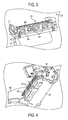
- Figure 4 shows a bottom view of embodiments herein, where the vacuum slit (orifice) 402 can be seen.
- Figure 4 also illustrates the paper exit guides 420 and the mounting points 404 of the paper exit module assembly 310 vacuum manifold 302.
- the vacuum manifold 302 can be an integral part of the paper exit module assembly 310 or can be a separate piece connected to the paper exit module assembly 310.
- Figure 5 shows a close-up of the bottom of the abatement manifold, again in cut-away view.
- FIGs 5 and 6 are cross-sectional schematic diagrams of paper exit module assemblies 310 positioned next to a surface that is to be cleaned, such as the drum 320 or other sensitive components including, but not limited to heads, photoreceptor, belt, roller, paper guide, sensor, etc.
- the vacuum manifold 302 is shown as a separate item within the paper exit module assembly 310; however, the vacuum manifold 302 does not need to utilize separate chamber walls, but instead can form a vacuum within the walls of the paper exit module assembly 310 (as illustrated in the embodiment is shown in Figures 3-5).
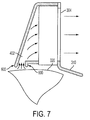
- Figures 3-5 and 7 illustrate structures where the vacuum is formed within the walls of the paper exit module assembly 310
- Figure 6 illustrates a different embodiment that includes a separate vacuum manifold 302 within the paper exit module assembly 310.
- the vacuum manifold 302 includes a contaminate exit module assembly 306 connected to duct work 308.
- the duct work 308 should be sent to an area external to the printer, through, for example a filter, etc. so that the contaminants do not retum to the drum 320.
- All embodiments within Figures 3-7 place one or more fans 304 between the vacuum orifice 402 and the paper exit module assembly 310. The fans 304 force air movement to draw air from the vacuum orifice 402 toward the contaminant exit module assembly 306 as shown by the arrows in Figure 6 in order to create a vacuum at the vacuum orifice 402.
- Figures 6 and 7 also illustrate optional ribs 600 or lips that can be attached or formed on the edges of the vacuum orifice 402 to increase the application of the vacuum to the drum/belt 320 or surface that is to be cleaned.
- These ribs 600 can be rigid or compliant allowing them to be placed very close to the drum 320, thereby applying a strong vacuum force to the drum 320 without risking damage or scratching of the drum 320.
- One of the features illustrated in the embodiments shown in Figures 3-7 is that by positioning the fan(s) internally within the paper exit module assembly 310 (or within a separate vacuum manifold assembly 302), the size of the paper exit module assembly can potentially be allowed to remain the same and not increase in size, or may increase in size only slightly. Further, because the fan(s) is so close to the vacuum orifice 402 (when compared to the external fan structure shown in Figure 2) it exerts a stronger vacuum force because the vacuum force does not need to travel through extensive ducting.
- vacuum abatement has general application to a wide variety of printing architectures, including xerographic and direct-to-paper ink jet printing.
- Embodiments herein described herein are suitable for and would give benefits to a wide variety of printing technologies, particularly those in which a compact, duct-less design is a requirement.
- embodiments herein comprise a compact dust abatement apparatus that includes at least one manifold shaped to fit next to a belt or drum of a printing engine, at least one blower/fan positioned within the manifold, and at least one air duct connected to the manifold.
- the manifold has a vacuum opening adjacent the belt or drum and an exit opening where the air duct connects to the manifold.
- the blower is positioned between the vacuum opening and the exit opening, such that the blower draws air and particles from the vacuum opening toward the exit opening.
- the blower creates a vacuum at the vacuum opening.
- the air duct directs air and particles from the manifold to a location away from sensitive components.
- the manifold can comprise an integrated portion of a paper exit module assembly of the printing engine or can be connected to the paper exit module assembly.
- the manifold has a size and shape to fit within a paper exit module assembly of the printing engine.
- the manifold has a size and shape to match the belt or drum and the manifold is quite compact.
- the manifold can be used with existing systems without significant modification. Indeed, when the manifold is included within, or as part of the paper exit module, it is about the same size of conventional paper exit modules.
Landscapes
- Physics & Mathematics (AREA)
- General Physics & Mathematics (AREA)
- Ink Jet (AREA)
- Control Or Security For Electrophotography (AREA)
- Electrophotography Configuration And Component (AREA)
Abstract
Description
- Vacuum abatement systems, which prevent contaminants from reaching critical printer components, typically consist of a manifold or nozzle, a vacuum source (e.g. blower or fan) and ducting to connect the vacuum source and the manifold. Physically separating the manifold and blower allows the manifold to be embedded in the architecture, closely spaced from the surfaces or elements being cleaned, with the blower located in some less space-restricted area. The drawback is the creation of additional resistance to abatement airflow by the connecting duct, which is often long and can have many bends. In addition to degrading the airflow in the abatement system, the ducting adds complexity and cost. The ducting itself may consist of several components, and connections and seals are needed on both the blower and manifold ends of the duct.
- As also discussed in
U.S. Patent Publication 2003/0170043 (incorporated herein by reference) dust, debris, and toner may adversely affect the development operation in image-forming machines. Dust from each development station may adversely affect the development process in the other development stations. If similarly charged, the airborne toner from one development station may adhere to the photoconductor in place of the toner from another development station. The blending of toner from different development stations also adversely affects the toner properties and subsequently the image quality. If oppositely charged, the airborne toner may blend with the toner from the other development station and may then be attracted to the non-image areas producing a background or fog in the image. - Some image-forming machines implement one or more approaches to remove or otherwise control the airborne toner and carrier. See, for example,
U.S. Patent Publication 2003/0052545 , andU.S. Patents 5,081,496 , and5,066,983 (all incorporated herein by reference) which utilize an external fan connected to a tube to create a vacuum near the cartridge or drum. A vacuum pump, fan, or other air movement device may be used to remove and filter the airborne toner from the air within the image-forming machine. Smaller vacuum pumps may be used to remove toner stacks or other build-up of toner in the image-forming machine. Some image-forming machines have a vacuum or electrostatic tube with several openings for applying a vacuum or an electrostatic charge along the trailing edge of the development station. These trailing edge openings collect airborne toner and carrier exiting along the trailing edge. - Embodiments herein comprise a compact dust abatement apparatus that includes at least one manifold shaped to fit next to a belt or drum of a printing engine, at least one blower positioned within the manifold, and at least one air duct connected to the manifold. The manifold has a vacuum opening adjacent the belt or drum and an exit opening where the air duct connects to the manifold. The blower is positioned inside the vacuum manifold, between the vacuum opening and the exit opening, such that the blower draws air and particles from the vacuum opening toward the exit opening. Thus, the blower creates a vacuum at the vacuum opening. The air duct directs air and particles from the manifold to a location away from the image drum or belt, or other sensitive component.
- The manifold can comprise an integrated portion of a paper exit module assembly of the printing engine or can be connected to the paper exit module assembly. In another embodiment, the manifold has a size and shape to fit within a paper exit module assembly of the printing engine.
- The manifold has a size and shape to match the belt or drum and the manifold is quite compact. Thus, the manifold can be used with existing systems without significant modification. Indeed, when the manifold is included within, or as part of the paper exit module, it is about the same size as conventional paper exit modules.
In one embodiment of the apparatus according to claim 9, said manifold has a size and shape to fit within a paper exit module assembly of said printing engine.
In one embodiment of the apparatus according toclaim 10, said manifold comprises a vacuum opening adjacent said image bearing member.
In a further embodiment said manifold comprises an exit opening wherein said air duct connects to said manifold.
In a further embodiment said blower is adapted to create a vacuum within said manifold. In a further embodiment said manifold has a size and shape to match said image bearing member. - These and other features are described in, or are apparent from, the following detailed description.
- Various exemplary embodiments of the systems and methods described in detail below, with reference to the attached drawing figures, in which:
- FIG. 1 is a graph showing rates of recoverable failures; and
- FIGS. 2-7 are schematic representations of dust abatement systems.
- Embodiments herein comprise a vacuum-based abatement system which incorporates the source of airflow (e.g., blowers/fans) inside the vacuum manifold itself In this case, the manifold serves multiple purposes: it provides the nozzle opening through which the cleaning takes place, it provides the cavity that holds the vacuum airflow source(s) in which the vacuum is generated, and it provides an exhaust opening through which the particle-laden air can pass to the outside of the printer, or to some suitable container which collects contaminants. The embodiment eliminates many of the interfaces of a vacuum abatement system with ducting to connect the vacuum source and manifold, thereby increasing compactness, and reducing cost and complexity. Such compact abatement systems are generally desirable, particularly for smaller printers.
- Embodiments herein comprise a vacuum manifold with internal fans to generate the airflow needed for contamination abatement. In solid ink printers, the image drum bears the image printed by the print head, and subsequently transfers this image to paper via the transfix operation. The image drum surface has been identified as a carrier of paper fibers and particulates to the print head. Cleaning of the intermediate image drum with vacuum abatement has been shown to reduce the number of print head failures. Many print head failures (intermittent weak or missing jets) are recoverable by performing a print head maintenance cycle, which, among other things, cleans dirt and stray ink from the print head aperture plate. Chronic weak or missing jets are permanent, and are often the result of contamination clogging one or more of the jetting apertures. Vacuum abatement is effective in reducing the rate of deposition of contaminants on the print head, thereby increasing print head reliability by reducing recoverable and permanent contamination-related failures.
- Print testing with solid ink printers has demonstrated the benefit of vacuum abatement in reducing the number of intermittent weak or missing jets (IWMs). Figure 1 below shows the rates of recoverable failures (IWMs) in printers with and without abatement. The values shown in Figure 1 are similar to those that are achieved by embodiments herein, although Figure 1 is not intended to demonstrate the performance of any specific embodiment herein. Instead, Figure 1 is utilized to generally demonstrate the benefit of contaminants abatement systems. Those printers with abatement have a failure rate which is approximately 50% lower than printers with no abatement.
- Figure 2 shows one vacuum abatement design, which uses a
tapered duct 202 to connect the remotely mountedblower 200 andvacuum manifold 204. The abatement systems in these printers usedmanifolds 204 supplied with airflow fromexternal blowers 200 as shown in Figure 2. Ducting 202 connects theblower 200 to thevacuum manifold 204. While this is acceptable for testing purposes, it is difficult to implement in products, particularly desktop printers, due to space limitations. Theducting 202 is also a source of airflow resistance, which reduces abatement effectiveness. Even in larger printers where ducting is justified, there is added complexity and cost associated with theduct 202 itself, and with the connections needed on both the manifold and blower sides. - An
embodiment 300 is shown in cut-away view in Figure 3. This particular design is intended for a solid ink printer, although it can be used with any type of printing engine. Thisvacuum manifold 302 contains three smallmuffin fan blowers 304, or any other device that moves air (herein referred to generally as "blower") mounted internally, to generate the airflow needed to remove paper fibers and dust from theimage drum 320 surface and surroundings. Thevacuum manifold 302 is integral with the paperexit module assembly 310. In the embodiment shown in Figure 1, thefans 304 are exposed to the outside of thevacuum manifold 302 which causes any debris that is drawn into thevacuum manifold 302 to directly exit the exposed portions of thefans 304. Therefore, this embodiment is designed to work without any duct work such asitem 202, showing Figure 2. This embodiment is designed to be positioned directly next to an external opening, filter, etc. so that the debris exiting from the exposed portions of thefans 304 will not return to theimage drum 320. - Embodiments herein allow the manifold to simultaneously serve as the nozzle through which contaminants are cleaned from the image drum, provide the enclosure in which the vacuum source is contained, and facilitate the exit of the abatement air stream, which is exhausted directly to the exterior of the printer, away from critical internal components (i.e., the print head), such as image bearing members of the printing engine. As used herein, and image bearing member can comprise any item within a printing engine which suffers substantial performance degradation if not kept free of debris and contaminants. Therefore, the image bearing members herein can comprise drums, belts, printheads, photoreceptors, etc.
- Due to its compactness, the entire abatement system can be mounted above the image drum, in or as part of the paper
exit module assembly 310. Also, even with its internally mounted fans, the design shown here is projected to cost significantly less than the conventional abatement systems, while still providing adequate airflow and pressure drop (approximately 7 - 8 cubic feet/min @ -0.01 inches of water, for example). Figure 1 shows the reliability benefit attained with vacuum abatement using a manifold with a remotely mounted blower, operating with the pressure and flow conditions previously mentioned. The compact design, if operated with similar pressure and air flow conditions, is expected to give a similar performance benefit. Figure 4 shows a bottom view of embodiments herein, where the vacuum slit (orifice) 402 can be seen. In this design, the contaminant-laden air stream from the abatement system is exhausted directly to the exterior of the printer. Figure 4 also illustrates the paper exit guides 420 and the mountingpoints 404 of the paperexit module assembly 310vacuum manifold 302. Again, thevacuum manifold 302 can be an integral part of the paperexit module assembly 310 or can be a separate piece connected to the paperexit module assembly 310. Figure 5 shows a close-up of the bottom of the abatement manifold, again in cut-away view. - Figures 5 and 6 are cross-sectional schematic diagrams of paper
exit module assemblies 310 positioned next to a surface that is to be cleaned, such as thedrum 320 or other sensitive components including, but not limited to heads, photoreceptor, belt, roller, paper guide, sensor, etc. Thevacuum manifold 302 is shown as a separate item within the paperexit module assembly 310; however, thevacuum manifold 302 does not need to utilize separate chamber walls, but instead can form a vacuum within the walls of the paper exit module assembly 310 (as illustrated in the embodiment is shown in Figures 3-5). Figures 3-5 and 7 illustrate structures where the vacuum is formed within the walls of the paperexit module assembly 310, while Figure 6 illustrates a different embodiment that includes aseparate vacuum manifold 302 within the paperexit module assembly 310. In the embodiment shown in Figure 6, thevacuum manifold 302 includes a contaminateexit module assembly 306 connected toduct work 308. As with the structure shown in Figure 2, theduct work 308 should be sent to an area external to the printer, through, for example a filter, etc. so that the contaminants do not retum to thedrum 320. All embodiments within Figures 3-7 place one ormore fans 304 between thevacuum orifice 402 and the paperexit module assembly 310. Thefans 304 force air movement to draw air from thevacuum orifice 402 toward the contaminantexit module assembly 306 as shown by the arrows in Figure 6 in order to create a vacuum at thevacuum orifice 402. - Figures 6 and 7 also illustrate
optional ribs 600 or lips that can be attached or formed on the edges of thevacuum orifice 402 to increase the application of the vacuum to the drum/belt 320 or surface that is to be cleaned. Theseribs 600 can be rigid or compliant allowing them to be placed very close to thedrum 320, thereby applying a strong vacuum force to thedrum 320 without risking damage or scratching of thedrum 320. - One of the features illustrated in the embodiments shown in Figures 3-7 is that by positioning the fan(s) internally within the paper exit module assembly 310 (or within a separate vacuum manifold assembly 302), the size of the paper exit module assembly can potentially be allowed to remain the same and not increase in size, or may increase in size only slightly. Further, because the fan(s) is so close to the vacuum orifice 402 (when compared to the external fan structure shown in Figure 2) it exerts a stronger vacuum force because the vacuum force does not need to travel through extensive ducting.
- It has been estimated that during the warranty period, the financial benefits of this type of abatement for solid ink will exceed the cost of the system. Additional calculations of the post-warranty financials indicate that the added reliability due to vacuum abatement will show up as a significant benefit to the customer, both in terms of extending the service life of the print head (saving the customer the cost of head replacement) and in reducing annoying customer interventions to recover intermittent jets. This has the potential for increasing the likelihood of repeat purchase of future products and of positive recommendations to other potential customers.
- While the data and implementations shown above are for solid ink printing with an intermediate image drum architecture, vacuum abatement has general application to a wide variety of printing architectures, including xerographic and direct-to-paper ink jet printing. Embodiments herein described herein are suitable for and would give benefits to a wide variety of printing technologies, particularly those in which a compact, duct-less design is a requirement.
- Thus, embodiments herein comprise a compact dust abatement apparatus that includes at least one manifold shaped to fit next to a belt or drum of a printing engine, at least one blower/fan positioned within the manifold, and at least one air duct connected to the manifold. The manifold has a vacuum opening adjacent the belt or drum and an exit opening where the air duct connects to the manifold. The blower is positioned between the vacuum opening and the exit opening, such that the blower draws air and particles from the vacuum opening toward the exit opening. Thus, the blower creates a vacuum at the vacuum opening. The air duct directs air and particles from the manifold to a location away from sensitive components.
- The manifold can comprise an integrated portion of a paper exit module assembly of the printing engine or can be connected to the paper exit module assembly. In another embodiment, the manifold has a size and shape to fit within a paper exit module assembly of the printing engine. The manifold has a size and shape to match the belt or drum and the manifold is quite compact. Thus, the manifold can be used with existing systems without significant modification. Indeed, when the manifold is included within, or as part of the paper exit module, it is about the same size of conventional paper exit modules.
Claims (10)
- An apparatus comprising:at least one manifold shaped to fit next to an image bearing member of a printing engine;at least one blower positioned within said manifold; andat least one air duct connected to said manifold.
- An apparatus comprising:at least one manifold shaped to fit next to an image bearing member of a printing engine;at least one blower positioned within said manifold; andat least one air duct connected to said manifold,wherein said manifold has a size and shape to match said image bearing member.
- The apparatus according to claim 1 or 2, wherein said manifold comprises an integrated portion of a paper exit module assembly of said printing engine.
- The apparatus according to claim 1 or 2, wherein said manifold comprises a vacuum opening adjacent said image bearing member and an exit opening where said air duct connects to said manifold.
- The apparatus according to claim 1 or 2, wherein said blower is adapted to create a vacuum within said manifold.
- The apparatus according to claim 1 or 2, wherein said air duct is adapted to direct air and particles from said manifold to a location away from said image bearing member.
- The apparatus according to claim 1 or 2, wherein said manifold has a size and shape to match said image bearing member.
- An apparatus comprising:at least one manifold shaped to fit next to an image bearing member of a printing engine, wherein said manifold comprises a vacuum opening adjacent said image bearing member;at least one blower positioned within said manifold;at least one air duct connected to said manifold,wherein said manifold comprises an exit opening where said air duct connects to said manifold,
wherein said blower is positioned between said vacuum opening and said exit opening, such that said blower blows air and particles from said vacuum opening toward said exit opening. - The apparatus according to claim 8, wherein said air duct is adapted to direct air and particles from said manifold to a location away from said image bearing member.
- An apparatus comprising:a paper exit module positioned next to an image bearing member of a printing engine;at least one manifold within said paper exit module, wherein said manifold has a shape to fit next to said image bearing member;at least one blower positioned within said manifold, wherein said blower is located within a central portion of said manifold; andat least one air duct connected to said manifold,wherein said manifold comprises an integrated portion of a paper exit module assembly of said printing engine.
Applications Claiming Priority (1)
| Application Number | Priority Date | Filing Date | Title |
|---|---|---|---|
| US11/125,431 US7123854B1 (en) | 2005-05-10 | 2005-05-10 | Printer contaminant abatement systems and methods |
Publications (3)
| Publication Number | Publication Date |
|---|---|
| EP1722280A2 true EP1722280A2 (en) | 2006-11-15 |
| EP1722280A3 EP1722280A3 (en) | 2011-09-28 |
| EP1722280B1 EP1722280B1 (en) | 2015-04-15 |
Family
ID=36791594
Family Applications (1)
| Application Number | Title | Priority Date | Filing Date |
|---|---|---|---|
| EP06113670.1A Ceased EP1722280B1 (en) | 2005-05-10 | 2006-05-09 | Printer contaminant abatement systems and methods |
Country Status (2)
| Country | Link |
|---|---|
| US (1) | US7123854B1 (en) |
| EP (1) | EP1722280B1 (en) |
Families Citing this family (5)
| Publication number | Priority date | Publication date | Assignee | Title |
|---|---|---|---|---|
| US8029124B2 (en) * | 2008-06-06 | 2011-10-04 | Xerox Corporation | System and method for encapsulating edges of paper in printers |
| JP5702191B2 (en) * | 2010-10-22 | 2015-04-15 | 株式会社ミマキエンジニアリング | Inkjet recording apparatus and printing method |
| EP2682268B1 (en) * | 2011-03-04 | 2017-02-15 | Mimaki Engineering Co., Ltd. | Inkjet recording device |
| JP5478649B2 (en) * | 2012-02-20 | 2014-04-23 | 京セラドキュメントソリューションズ株式会社 | Image forming apparatus |
| US20170088298A1 (en) * | 2015-09-25 | 2017-03-30 | Multi-Pack Solutions, LLC | Packaging machine with independently controllable movers |
Citations (5)
| Publication number | Priority date | Publication date | Assignee | Title |
|---|---|---|---|---|
| JPS5532066A (en) | 1978-08-29 | 1980-03-06 | Fujitsu Ltd | Cleaning device |
| JPS58137868A (en) | 1982-02-10 | 1983-08-16 | Fuji Xerox Co Ltd | Cleaning device of electrophotographic copying machine |
| US5066983A (en) | 1987-12-18 | 1991-11-19 | Fujitsu Limited | Cleaning unit for cleaning recording medium of an electrophotographic apparatus |
| US5081496A (en) | 1989-03-28 | 1992-01-14 | Canon Kabushiki Kaisha | Image forming apparatus having a ventilated contact charging unit |
| US20030052545A1 (en) | 2001-09-14 | 2003-03-20 | Samsung Electronics Co., Ltd. | Circuit for stabilizing high tension voltage of CRT, and method thereof |
Family Cites Families (6)
| Publication number | Priority date | Publication date | Assignee | Title |
|---|---|---|---|---|
| US3743540A (en) * | 1971-08-30 | 1973-07-03 | F Hudson | Surface cleaning by ionized flow |
| KR200147792Y1 (en) * | 1997-06-30 | 1999-06-15 | 윤종용 | Wet electrophotographic printer |
| US6453147B1 (en) * | 2000-08-16 | 2002-09-17 | Nexpress Solutions Llc | Dust control in conductive-core fiber brush cleaning systems using self-generated air flow |
| US6411788B1 (en) * | 2000-11-28 | 2002-06-25 | Toshiba Tec Kabushiki Kaisha | Image forming apparatus with air flow regulator |
| US6621995B1 (en) | 2002-03-11 | 2003-09-16 | Heidelberger Druckmaschinen Ag | Image-forming machine having a development station with a dusting control system |
| KR100467607B1 (en) * | 2002-08-22 | 2005-01-24 | 삼성전자주식회사 | Fuser of liquid type image forming system having carrier vapor dilution apparatus and liquid type image forming system using it |
-
2005
- 2005-05-10 US US11/125,431 patent/US7123854B1/en not_active Expired - Fee Related
-
2006
- 2006-05-09 EP EP06113670.1A patent/EP1722280B1/en not_active Ceased
Patent Citations (5)
| Publication number | Priority date | Publication date | Assignee | Title |
|---|---|---|---|---|
| JPS5532066A (en) | 1978-08-29 | 1980-03-06 | Fujitsu Ltd | Cleaning device |
| JPS58137868A (en) | 1982-02-10 | 1983-08-16 | Fuji Xerox Co Ltd | Cleaning device of electrophotographic copying machine |
| US5066983A (en) | 1987-12-18 | 1991-11-19 | Fujitsu Limited | Cleaning unit for cleaning recording medium of an electrophotographic apparatus |
| US5081496A (en) | 1989-03-28 | 1992-01-14 | Canon Kabushiki Kaisha | Image forming apparatus having a ventilated contact charging unit |
| US20030052545A1 (en) | 2001-09-14 | 2003-03-20 | Samsung Electronics Co., Ltd. | Circuit for stabilizing high tension voltage of CRT, and method thereof |
Also Published As
| Publication number | Publication date |
|---|---|
| EP1722280A3 (en) | 2011-09-28 |
| EP1722280B1 (en) | 2015-04-15 |
| US7123854B1 (en) | 2006-10-17 |
Similar Documents
| Publication | Publication Date | Title |
|---|---|---|
| JP5407697B2 (en) | Image forming apparatus | |
| US8506072B2 (en) | Printing apparatus | |
| EP0916509B1 (en) | Ink jet recording apparatus | |
| CN102066116A (en) | Inkjet printer | |
| CN107053842A (en) | Liquid ejection apparatus | |
| EP0916510B1 (en) | Ink jet recording apparatus | |
| JP2008093849A (en) | Droplet discharge head and droplet discharge apparatus | |
| US7123854B1 (en) | Printer contaminant abatement systems and methods | |
| US9465359B2 (en) | Air blowing system and image forming apparatus including same | |
| JP2006076155A (en) | Image forming apparatus | |
| JP2024060215A (en) | Inkjet recording device | |
| US8634741B2 (en) | Laser printer cleaning cartridge device and method | |
| JP2017213714A (en) | Printing device | |
| JP6236984B2 (en) | Droplet discharge device | |
| US7512357B2 (en) | Image forming device arranged with plural particle removal devices | |
| JP2004330599A (en) | Ink jet recorder | |
| JP2004284184A (en) | Ink jet recorder | |
| JP2005145021A (en) | Inkjet recorder | |
| JP2000246983A (en) | Image-forming apparatus | |
| US20250108618A1 (en) | Image forming apparatus | |
| JP2020006525A (en) | Air intake system, and inkjet recording device | |
| JP4449440B2 (en) | Image forming apparatus | |
| JP3535714B2 (en) | Ink jet recording device | |
| JP4373856B2 (en) | Developer scattering prevention device, developing device, and image forming apparatus | |
| JP2004130624A (en) | Inkjet recording device |
Legal Events
| Date | Code | Title | Description |
|---|---|---|---|
| PUAI | Public reference made under article 153(3) epc to a published international application that has entered the european phase |
Free format text: ORIGINAL CODE: 0009012 |
|
| AK | Designated contracting states |
Kind code of ref document: A2 Designated state(s): AT BE BG CH CY CZ DE DK EE ES FI FR GB GR HU IE IS IT LI LT LU LV MC NL PL PT RO SE SI SK TR |
|
| AX | Request for extension of the european patent |
Extension state: AL BA HR MK YU |
|
| PUAL | Search report despatched |
Free format text: ORIGINAL CODE: 0009013 |
|
| AK | Designated contracting states |
Kind code of ref document: A3 Designated state(s): AT BE BG CH CY CZ DE DK EE ES FI FR GB GR HU IE IS IT LI LT LU LV MC NL PL PT RO SE SI SK TR |
|
| AX | Request for extension of the european patent |
Extension state: AL BA HR MK YU |
|
| RIC1 | Information provided on ipc code assigned before grant |
Ipc: G03G 21/00 20060101AFI20110824BHEP |
|
| 17P | Request for examination filed |
Effective date: 20120328 |
|
| AKX | Designation fees paid |
Designated state(s): DE FR GB |
|
| 17Q | First examination report despatched |
Effective date: 20140704 |
|
| GRAP | Despatch of communication of intention to grant a patent |
Free format text: ORIGINAL CODE: EPIDOSNIGR1 |
|
| INTG | Intention to grant announced |
Effective date: 20141128 |
|
| GRAS | Grant fee paid |
Free format text: ORIGINAL CODE: EPIDOSNIGR3 |
|
| GRAA | (expected) grant |
Free format text: ORIGINAL CODE: 0009210 |
|
| AK | Designated contracting states |
Kind code of ref document: B1 Designated state(s): DE FR GB |
|
| REG | Reference to a national code |
Ref country code: GB Ref legal event code: FG4D |
|
| REG | Reference to a national code |
Ref country code: DE Ref legal event code: R096 Ref document number: 602006045104 Country of ref document: DE Effective date: 20150528 |
|
| REG | Reference to a national code |
Ref country code: DE Ref legal event code: R097 Ref document number: 602006045104 Country of ref document: DE |
|
| PLBE | No opposition filed within time limit |
Free format text: ORIGINAL CODE: 0009261 |
|
| STAA | Information on the status of an ep patent application or granted ep patent |
Free format text: STATUS: NO OPPOSITION FILED WITHIN TIME LIMIT |
|
| 26N | No opposition filed |
Effective date: 20160118 |
|
| REG | Reference to a national code |
Ref country code: FR Ref legal event code: PLFP Year of fee payment: 11 |
|
| REG | Reference to a national code |
Ref country code: FR Ref legal event code: PLFP Year of fee payment: 12 |
|
| PGFP | Annual fee paid to national office [announced via postgrant information from national office to epo] |
Ref country code: DE Payment date: 20170420 Year of fee payment: 12 Ref country code: GB Payment date: 20170426 Year of fee payment: 12 Ref country code: FR Payment date: 20170421 Year of fee payment: 12 |
|
| REG | Reference to a national code |
Ref country code: DE Ref legal event code: R119 Ref document number: 602006045104 Country of ref document: DE |
|
| GBPC | Gb: european patent ceased through non-payment of renewal fee |
Effective date: 20180509 |
|
| PG25 | Lapsed in a contracting state [announced via postgrant information from national office to epo] |
Ref country code: GB Free format text: LAPSE BECAUSE OF NON-PAYMENT OF DUE FEES Effective date: 20180509 Ref country code: FR Free format text: LAPSE BECAUSE OF NON-PAYMENT OF DUE FEES Effective date: 20180531 Ref country code: DE Free format text: LAPSE BECAUSE OF NON-PAYMENT OF DUE FEES Effective date: 20181201 |