EP1722218A1 - Device for measuring the humidity of materials, particularly textiles - Google Patents
Device for measuring the humidity of materials, particularly textiles Download PDFInfo
- Publication number
- EP1722218A1 EP1722218A1 EP05103813A EP05103813A EP1722218A1 EP 1722218 A1 EP1722218 A1 EP 1722218A1 EP 05103813 A EP05103813 A EP 05103813A EP 05103813 A EP05103813 A EP 05103813A EP 1722218 A1 EP1722218 A1 EP 1722218A1
- Authority
- EP
- European Patent Office
- Prior art keywords
- circuit
- measuring device
- humidity
- electrical
- coil
- Prior art date
- Legal status (The legal status is an assumption and is not a legal conclusion. Google has not performed a legal analysis and makes no representation as to the accuracy of the status listed.)
- Granted
Links
Images



Classifications
-
- G—PHYSICS
- G01—MEASURING; TESTING
- G01N—INVESTIGATING OR ANALYSING MATERIALS BY DETERMINING THEIR CHEMICAL OR PHYSICAL PROPERTIES
- G01N27/00—Investigating or analysing materials by the use of electric, electrochemical, or magnetic means
- G01N27/02—Investigating or analysing materials by the use of electric, electrochemical, or magnetic means by investigating impedance
- G01N27/04—Investigating or analysing materials by the use of electric, electrochemical, or magnetic means by investigating impedance by investigating resistance
- G01N27/048—Investigating or analysing materials by the use of electric, electrochemical, or magnetic means by investigating impedance by investigating resistance for determining moisture content of the material
-
- D—TEXTILES; PAPER
- D06—TREATMENT OF TEXTILES OR THE LIKE; LAUNDERING; FLEXIBLE MATERIALS NOT OTHERWISE PROVIDED FOR
- D06F—LAUNDERING, DRYING, IRONING, PRESSING OR FOLDING TEXTILE ARTICLES
- D06F34/00—Details of control systems for washing machines, washer-dryers or laundry dryers
- D06F34/14—Arrangements for detecting or measuring specific parameters
- D06F34/18—Condition of the laundry, e.g. nature or weight
-
- D—TEXTILES; PAPER
- D06—TREATMENT OF TEXTILES OR THE LIKE; LAUNDERING; FLEXIBLE MATERIALS NOT OTHERWISE PROVIDED FOR
- D06F—LAUNDERING, DRYING, IRONING, PRESSING OR FOLDING TEXTILE ARTICLES
- D06F2103/00—Parameters monitored or detected for the control of domestic laundry washing machines, washer-dryers or laundry dryers
- D06F2103/02—Characteristics of laundry or load
- D06F2103/08—Humidity
- D06F2103/10—Humidity expressed as capacitance or resistance
-
- D—TEXTILES; PAPER
- D06—TREATMENT OF TEXTILES OR THE LIKE; LAUNDERING; FLEXIBLE MATERIALS NOT OTHERWISE PROVIDED FOR
- D06F—LAUNDERING, DRYING, IRONING, PRESSING OR FOLDING TEXTILE ARTICLES
- D06F58/00—Domestic laundry dryers
- D06F58/32—Control of operations performed in domestic laundry dryers
- D06F58/34—Control of operations performed in domestic laundry dryers characterised by the purpose or target of the control
- D06F58/52—Preventing or reducing noise
Definitions
- the present invention relates to a measuring device for measuring the humidity of materials, in particular the humidity of textiles.
- the materials may be in a electrically conductive container as is the case, for example, with a laundry dryer.
- a measuring device wherein the specific electrical conductivity of the textiles is measured depending on the humidity.
- this device When this device is applied in a rotating drum of a dryer, sliding electrical contacts are necessary for contacting the wet laundry. Therefore such known device generally comprises a first and a second brush electrically connected to an electronic evaluation circuit able to process the signals provided by the brushes to give an indication of the laundry humidity level inside the dryer drum.
- the first brush is positioned in slidable contact with a first half of the dryer drum and the second brush is positioned in slidable contact with the drum spindle.
- the two halves of the drum are made in a conductive material and are separated by an insulating strip made, for example, of plastic material. When the drum is empty the impedance between the two halves is virtually infinite while it varies according to the laundry load, the type of fabric and the degree of the humidity when the laundry is placed in the drum.
- Such known device is of relatively complicated mechanical construction and, furthermore, it has a limited reliability because of wearing of the creeping brushes. For this reason a scheduled maintenance must be supplied causing the drying machine to be undesirably stopped. In addition, an undesired noise is always caused by the brush creeping when the drying machine is working.
- the aim of the present invention is therefore to solve the noted problems, eliminating the drawbacks of the cited known art and thus providing a measuring device for measuring the humidity of materials, in particular the humidity of textiles, in which mechanical contacts are eliminated.
- a further purpose of the present invention is to provide a measuring device for measuring the humidity of materials that eliminates the noise production in working condition.
- Another purpose of the present invention is to provide a measuring device for measuring the humidity of materials having an improved reliability, said device being simple to be made and easy to be assembled in a laundry dryer.
- Figure 1 shows in a schematic block diagram the circuit of a measuring device according to the invention
- Figure 2 shows an electronic circuit corresponding to the circuit of figure 1;
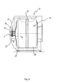
- Figure 3 shows a laundry drying machine comprising the humidity degree measuring device.
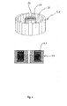
- Figure 4 shows an embodiment of the ferromagnetic element incorporating a coil.
- Figure 5 shows, in a logarithmic scale, the trend of the time between two subsequent impulse signals output by the output means in response to a variable electrical resistance of a wet material.
- the measuring device comprises a primary electrical circuit 1 shown within the closed line named "P" and a secondary electrical circuit 2 shown within the closed line named "S".
- Primary circuit 1 comprises a first ferromagnetic element 3 having a first coil 4 wrapped around.
- the coil 4 is electrically powered by an oscillatory circuit 5 able to supply an alternating voltage at a set frequency.
- the oscillatory circuit 5 is known per se.
- the secondary circuit 2 that is physically separated from the primary circuit 1, comprises a second ferromagnetic element 6 that must be placed in a position facing the first element 3 in order to have the measuring device working correctly and efficiently.
- a second coil 7 is wrapped around the element 6 and it is in electrical communication with an evaluation circuit named EC having electrical terminals 8 and 9. These terminals coincide with the terminals of the secondary circuit 2.
- the secondary circuit 2 is powered by the primary circuit 1 by means of the coupling of elements 3 and 6, while the same coupling is able to transfer a signal from the secondary circuit to the primary one as described in grater detail below.
- Switching means 10 are provided in the evaluation circuit EC such that when a wet material, i.e. an electric load, is placed in contact with the terminals 8 and 9, the evaluation circuit EC causes the switching means 10 to short-circuit the second coil 7 a number of times dependent on the electrical resistence of the wet material.
- the effect of the switching means 10 short-circuiting is transferred to the primary circuit 1 by means of the ferromagnetic elements 3 and 6, and output means 11 shown in the closed dashed line named OP, like for example a voltmeter, is provided for outputting signals in response to the short-circuiting of the switching means 10.
- Data processing means can be provided in order to convert the output emitted by the output means 11 in a parameter indicative of the material humidity degree.
- Such parameter can be, for example, the time between two subsequent impulse signals output by the output means 11 and corresponding to the short-circuiting effect from the secondary to the primary circuit.
- FIG 5 it is illustrated the variation of the time between two subsequent impulse signals output by the output means 11 in response to a variable electrical resistance of a wet material.
- FIG. 2 A detailed embodiment of the electrical circuits of the measuring device according to the invention is shown in figure 2. Electrical components corresponding to those shown in the schematic block diagram of figure 1 have been numbered correspondingly in figure 2.
- primary and secondary circuits 1 and 2 are physically separated and but in electro-magnetical communication thanks to the provision of ferromagnetic elements 3, 6 and coils 4, 7.
- This configuration allows to make a material humidity measurement even if this material is in motion. This is the case of wet laundry placed in a drying machine rotatable drum.
- FIG 3 a laundry drying machine 12 comprising the humidity measuring device described above.
- the dryer 12 comprises a main structure 13 forming the machine containing body.
- the primary circuit 1 of the measuring device is stably fixed on the main structure 13 by means of a first board 15.
- the secondary circuit 2 is carried by a second board 16 mounted on the rotatable drying drum 14 and rotating together with the latter.
- Said drum 14 is formed by two joined halves 17, 18 made of an electrically conductive material, and by an electrically insulating strip 19 interposed between the halves such that the latter are insulated from each other.
- Each electrical terminal 8 and 9 is connected to one half of the drum 14 such that a current can flow between the terminals 8 and 9 passing through the laundry contained in the drum 14.
- the humidity degree of the laundry is measured by the measuring device in the above described manner. Since the laundry is progressively dried by the drying machine, its electrical resistance will change typically from a value of about 10 kohm, corresponding to laundry having a humidity grater than 20% of laundry weight (laundry completely wet), to a value of about 100Mohm corresponding to laundry having a humidity lower than 2% of laundry weight (laundry completely dried). A trend of the time measured between two subsequent impulse signals output by the output means 11 in response to the progressively changing electrical resistance of wet laundry to be dried is shown in figure 5.
- the humidity measurement can be carried out even when the drying machine is working, i.e. when the drum is in motion, without the need of sliding electrical contacts.
- Ferromagnetic elements 3 and 6 of the primary and secondary circuits 1 and 2 are provided respectively on the boards 15, 16 such that they are facing each other.
- the element 6 rotates with the drum 14, it is important to ensure a correct match of the ferromagnetic elements independently of their reciprocal orientation. This is obtained forming the elements 3 and 6 with a cylindrical shape and providing them with a central core 20 and with an annular groove 21. A ferromagnetic element so formed is shown in figure 4. Each coil 4, 7 is placed within the groove 21 and wrapped around the cylindrical outer surface of the core 20.
- the core 20 has a through hole 22 disposed along the longitudinal axis of the element 3, 6 for mounting the latter on a support structure not shown in figure 4.
- the output emitted by the output means 11 connected with the fixed board 15 can be sent to a drying machine programming unit by means of a electrical connection for influencing the machine working parameters according to the measured laundry degree of humidity.
- Said unit 23 can process the output adjusting the duration of the drying cycle and/or the heating intensity depending on the actual value of the laundry humidity.
Landscapes
- Chemical & Material Sciences (AREA)
- General Health & Medical Sciences (AREA)
- Immunology (AREA)
- Physics & Mathematics (AREA)
- Health & Medical Sciences (AREA)
- Life Sciences & Earth Sciences (AREA)
- Analytical Chemistry (AREA)
- Biochemistry (AREA)
- Chemical Kinetics & Catalysis (AREA)
- Electrochemistry (AREA)
- Pathology (AREA)
- General Physics & Mathematics (AREA)
- Engineering & Computer Science (AREA)
- Textile Engineering (AREA)
- Control Of Washing Machine And Dryer (AREA)
- Investigating Or Analyzing Materials By The Use Of Electric Means (AREA)
- Treatment Of Fiber Materials (AREA)
- Investigating Or Analyzing Materials Using Thermal Means (AREA)
Abstract
Description
- The present invention relates to a measuring device for measuring the humidity of materials, in particular the humidity of textiles. The materials may be in a electrically conductive container as is the case, for example, with a laundry dryer.
- A measuring device is already known, wherein the specific electrical conductivity of the textiles is measured depending on the humidity. When this device is applied in a rotating drum of a dryer, sliding electrical contacts are necessary for contacting the wet laundry. Therefore such known device generally comprises a first and a second brush electrically connected to an electronic evaluation circuit able to process the signals provided by the brushes to give an indication of the laundry humidity level inside the dryer drum. The first brush is positioned in slidable contact with a first half of the dryer drum and the second brush is positioned in slidable contact with the drum spindle. The two halves of the drum are made in a conductive material and are separated by an insulating strip made, for example, of plastic material. When the drum is empty the impedance between the two halves is virtually infinite while it varies according to the laundry load, the type of fabric and the degree of the humidity when the laundry is placed in the drum.
- Such known device is of relatively complicated mechanical construction and, furthermore, it has a limited reliability because of wearing of the creeping brushes. For this reason a scheduled maintenance must be supplied causing the drying machine to be undesirably stopped. In addition, an undesired noise is always caused by the brush creeping when the drying machine is working.
- The aim of the present invention is therefore to solve the noted problems, eliminating the drawbacks of the cited known art and thus providing a measuring device for measuring the humidity of materials, in particular the humidity of textiles, in which mechanical contacts are eliminated.
- A further purpose of the present invention is to provide a measuring device for measuring the humidity of materials that eliminates the noise production in working condition.
- Another purpose of the present invention is to provide a measuring device for measuring the humidity of materials having an improved reliability, said device being simple to be made and easy to be assembled in a laundry dryer.
- Advantages, objects, and features of the invention will be set forth in part in the description which follows and in part will become apparent to those having ordinary skill in the art upon examination of the following or may be learned from practice of the invention. The objects and advantages of the invention may be realised and attained as particularly pointed out in the appended claims.
- The accompanying drawings, which are included to provide a further understanding of the invention and are incorporated in and constitute a part of this specification, illustrate one of the possible embodiment of the invention and together with the description serve to explain the principles of the invention.
- In the drawings:
- Figure 1 shows in a schematic block diagram the circuit of a measuring device according to the invention;
- Figure 2 shows an electronic circuit corresponding to the circuit of figure 1;
- Figure 3 shows a laundry drying machine comprising the humidity degree measuring device.
- Figure 4 shows an embodiment of the ferromagnetic element incorporating a coil.
- Figure 5 shows, in a logarithmic scale, the trend of the time between two subsequent impulse signals output by the output means in response to a variable electrical resistance of a wet material.
- With reference to figure 1 the measuring device according to the invention comprises a primary
electrical circuit 1 shown within the closed line named "P" and a secondaryelectrical circuit 2 shown within the closed line named "S".Primary circuit 1 comprises a first ferromagnetic element 3 having afirst coil 4 wrapped around. Thecoil 4 is electrically powered by an oscillatory circuit 5 able to supply an alternating voltage at a set frequency. The oscillatory circuit 5 is known per se. - The
secondary circuit 2, that is physically separated from theprimary circuit 1, comprises a secondferromagnetic element 6 that must be placed in a position facing the first element 3 in order to have the measuring device working correctly and efficiently. A second coil 7 is wrapped around theelement 6 and it is in electrical communication with an evaluation circuit named EC havingelectrical terminals secondary circuit 2. - The
ferromagnetic elements 3 and 6, taken together, forms a magnetic circuit interrupted by an air gap, therefore a sort of electric transformer is formed by theelements 3 and 6 and thecoils 4 and 7. Thesecondary circuit 2 is powered by theprimary circuit 1 by means of the coupling ofelements 3 and 6, while the same coupling is able to transfer a signal from the secondary circuit to the primary one as described in grater detail below. - Switching means 10 are provided in the evaluation circuit EC such that when a wet material, i.e. an electric load, is placed in contact with the
terminals - The effect of the switching means 10 short-circuiting is transferred to the
primary circuit 1 by means of theferromagnetic elements 3 and 6, and output means 11 shown in the closed dashed line named OP, like for example a voltmeter, is provided for outputting signals in response to the short-circuiting of the switching means 10. - Data processing means, not shown in figure 1, can be provided in order to convert the output emitted by the output means 11 in a parameter indicative of the material humidity degree. Such parameter can be, for example, the time between two subsequent impulse signals output by the output means 11 and corresponding to the short-circuiting effect from the secondary to the primary circuit.
- In figure 5 it is illustrated the variation of the time between two subsequent impulse signals output by the output means 11 in response to a variable electrical resistance of a wet material. In the graphic time T is shown in a logarithmic scale. Said time, named T, can be calculated with the following relation when the electrical resistance Rx is known: T=1.2 * 10-7 * (30 * 104 + Rx).
- A detailed embodiment of the electrical circuits of the measuring device according to the invention is shown in figure 2. Electrical components corresponding to those shown in the schematic block diagram of figure 1 have been numbered correspondingly in figure 2.
- As mentioned above, primary and
secondary circuits ferromagnetic elements 3, 6 andcoils 4, 7. This configuration allows to make a material humidity measurement even if this material is in motion. This is the case of wet laundry placed in a drying machine rotatable drum. - In figure 3 is shown a
laundry drying machine 12 comprising the humidity measuring device described above. Thedryer 12 comprises amain structure 13 forming the machine containing body. Theprimary circuit 1 of the measuring device is stably fixed on themain structure 13 by means of afirst board 15. Thesecondary circuit 2 is carried by asecond board 16 mounted on therotatable drying drum 14 and rotating together with the latter. Saiddrum 14 is formed by two joined halves 17, 18 made of an electrically conductive material, and by an electrically insulating strip 19 interposed between the halves such that the latter are insulated from each other. Eachelectrical terminal drum 14 such that a current can flow between theterminals drum 14. - The humidity degree of the laundry is measured by the measuring device in the above described manner. Since the laundry is progressively dried by the drying machine, its electrical resistance will change typically from a value of about 10 kohm, corresponding to laundry having a humidity grater than 20% of laundry weight (laundry completely wet), to a value of about 100Mohm corresponding to laundry having a humidity lower than 2% of laundry weight (laundry completely dried). A trend of the time measured between two subsequent impulse signals output by the output means 11 in response to the progressively changing electrical resistance of wet laundry to be dried is shown in figure 5.
- The humidity measurement can be carried out even when the drying machine is working, i.e. when the drum is in motion, without the need of sliding electrical contacts.
-
Ferromagnetic elements 3 and 6 of the primary andsecondary circuits boards - Since the
element 6 rotates with thedrum 14, it is important to ensure a correct match of the ferromagnetic elements independently of their reciprocal orientation. This is obtained forming theelements 3 and 6 with a cylindrical shape and providing them with acentral core 20 and with anannular groove 21. A ferromagnetic element so formed is shown in figure 4. Eachcoil 4, 7 is placed within thegroove 21 and wrapped around the cylindrical outer surface of thecore 20. Thecore 20 has a throughhole 22 disposed along the longitudinal axis of theelement 3, 6 for mounting the latter on a support structure not shown in figure 4. - The output emitted by the output means 11 connected with the fixed
board 15 can be sent to a drying machine programming unit by means of a electrical connection for influencing the machine working parameters according to the measured laundry degree of humidity. Saidunit 23 can process the output adjusting the duration of the drying cycle and/or the heating intensity depending on the actual value of the laundry humidity. - As the present invention may be embodied in several forms without departing from the spirit or essential characteristics thereof, it should also be understood that the above-described embodiment is not limited by any of the details of the foregoing description, but rather should be construed broadly within its spirit and scope as defined in the appended claims, and therefore all changes and modifications that fall within the meets and bounds of the claims, or equivalence of such meets and bounds are therefore intended to be embraced by the appended claims.
Claims (9)
- A measuring device for measuring the humidity of materials, particularly textiles, comprising an evaluation circuit EC having electrical terminals (8, 9) and an oscillatory circuit (5), characterised by further comprising: □ a primary electrical circuit (1) comprising a first ferromagnetic element (3) having a first electric coil (4) wrapped around, said first coil being electrically powered by said oscillatory circuit (5); D a secondary electrical circuit (2) comprising a second ferromagnetic element (6), contactlessly facing the first ferromagnetic element, having a second electric coil (7) wrapped around, said second coil (7) being in electrical communication with said evaluation circuit EC; D switching means (10), provided in said evaluation circuit EC, for short-circuiting the second coil (7) in response to the electrical resistance of an electric load connected to the electrical terminals (8, 9); D output means (11) for outputting signals in response to the short-circuiting of the switching means (10);
- A measuring device according to claim 1 further comprising data processing means adapted to convert the output of said output means (11) in a parameter indicative of the humidity degree.
- A measuring device according to claim 2 wherein said parameter is a time comprised between two subsequent impulse signals emitted by said output means (11)
- A measuring device according to any preceding claim wherein the output means (10) are provided in the primary circuit (1).
- A measuring device according to any preceding claim wherein each of said first and the second ferromagnetic element (3, 6) have a cylindrical shape and are provided with a central core (20) and an annular groove (21) for receiving one of said first and second coil (4, 7) wrapped around said core (20).
- A laundry drying machine comprising a measuring device according to claim 1 to 5.
- A laundry drying machine according to claim 6 comprising a main structure (13) carrying the primary circuit (1) and a drum (14) adapted to receive laundry to be dried and able to rotate in respect to said structure (13), the drum being formed by two joined halves (17, 18), made of electrically conductive material, and an electrically insulating strip (19) interposed between the halves (17, 18), the drum (14) comprising a board (16) stably fixed on it and incorporating the secondary circuit (2).
- A laundry drying machine according to claim 7 wherein each drum halves (17, 18) is connected with one of said electrical terminals (8, 9).
- A laundry drying machine according to claim 7 or 8 wherein the output means (11) are electrically connected to a drying machine programming unit (23) for influencing the drying machine working parameters according to the laundry degree of humidity.
Priority Applications (5)
| Application Number | Priority Date | Filing Date | Title |
|---|---|---|---|
| PL05103813T PL1722218T3 (en) | 2005-05-09 | 2005-05-09 | Device for measuring the humidity of materials, particularly textiles |
| AT05103813T ATE515694T1 (en) | 2005-05-09 | 2005-05-09 | DEVICE FOR MOISTURE MEASUREMENT OF MATERIALS, IN PARTICULAR TEXTILES |
| ES05103813T ES2369366T3 (en) | 2005-05-09 | 2005-05-09 | MEASUREMENT DEVICE FOR MEASUREMENT OF MOISTURE OF MATERIALS, PARTICULARLY TEXTILE. |
| EP05103813A EP1722218B1 (en) | 2005-05-09 | 2005-05-09 | Device for measuring the humidity of materials, particularly textiles |
| US11/415,629 US7526956B2 (en) | 2005-05-09 | 2006-05-02 | Measuring device for measuring the humidity of materials, particularly textiles |
Applications Claiming Priority (1)
| Application Number | Priority Date | Filing Date | Title |
|---|---|---|---|
| EP05103813A EP1722218B1 (en) | 2005-05-09 | 2005-05-09 | Device for measuring the humidity of materials, particularly textiles |
Publications (2)
| Publication Number | Publication Date |
|---|---|
| EP1722218A1 true EP1722218A1 (en) | 2006-11-15 |
| EP1722218B1 EP1722218B1 (en) | 2011-07-06 |
Family
ID=34939734
Family Applications (1)
| Application Number | Title | Priority Date | Filing Date |
|---|---|---|---|
| EP05103813A Expired - Lifetime EP1722218B1 (en) | 2005-05-09 | 2005-05-09 | Device for measuring the humidity of materials, particularly textiles |
Country Status (5)
| Country | Link |
|---|---|
| US (1) | US7526956B2 (en) |
| EP (1) | EP1722218B1 (en) |
| AT (1) | ATE515694T1 (en) |
| ES (1) | ES2369366T3 (en) |
| PL (1) | PL1722218T3 (en) |
Families Citing this family (6)
| Publication number | Priority date | Publication date | Assignee | Title |
|---|---|---|---|---|
| US8015726B2 (en) * | 2005-06-23 | 2011-09-13 | Whirlpool Corporation | Automatic clothes dryer |
| US9249539B2 (en) | 2006-09-25 | 2016-02-02 | Ecolab Inc. | Determination of dryness of textiles in a dryer |
| US8782922B2 (en) | 2010-11-24 | 2014-07-22 | Ecolab Usa Inc. | Dryer monitoring |
| US9206543B2 (en) | 2011-10-14 | 2015-12-08 | Ecolab Usa Inc. | Dryer monitoring |
| TWM569412U (en) * | 2018-08-07 | 2018-11-01 | 捷騰光電股份有限公司 | Drying device for temperature and humidity sensing module |
| CA3182024A1 (en) | 2020-06-19 | 2021-12-23 | Peter J. MCGRANE | Embedded temperature sensors for monitoring temperature of articles and status of drying or cleaning cycles |
Citations (5)
| Publication number | Priority date | Publication date | Assignee | Title |
|---|---|---|---|---|
| US3203107A (en) * | 1962-09-07 | 1965-08-31 | Philco Corp | Dryer control using thermally magnetizable elements |
| US3287817A (en) * | 1965-08-04 | 1966-11-29 | Maytag Co | Method of using an electrode probe for electronic drier control |
| FR2399019A1 (en) * | 1977-07-29 | 1979-02-23 | Crouzet Sa | Dampness detector to switch off tumbler dryer for washing - after drying transmits signal from drum via air gap |
| DE3720164A1 (en) * | 1986-06-17 | 1987-12-23 | Tokyo Keiki Kk | Magnetic induction coupling system for contact-free transmission of a signal between at least two units |
| EP0565976A1 (en) * | 1992-04-16 | 1993-10-20 | ZELTRON S.p.A. | Household appliance with electronic control driven by peripheral units |
Family Cites Families (9)
| Publication number | Priority date | Publication date | Assignee | Title |
|---|---|---|---|---|
| US2217220A (en) * | 1938-12-17 | 1940-10-08 | Gen Electric | Electric measuring apparatus |
| US3032729A (en) * | 1957-05-16 | 1962-05-01 | Phillips Petroleum Co | Temperature stable transformer |
| US3167734A (en) * | 1959-11-27 | 1965-01-26 | Gen Motors Corp | Humidity sensing element |
| US3286363A (en) * | 1964-03-24 | 1966-11-22 | Gen Electric | Fabric dryer controls |
| US3445676A (en) * | 1967-02-21 | 1969-05-20 | Controls Co Of America | Moisture sensing control circuit detecting reversed polarity of power supply |
| US3824477A (en) * | 1969-03-03 | 1974-07-16 | Maytag Co | Ground sensitive control for electrical apparatus |
| US3595070A (en) * | 1969-12-22 | 1971-07-27 | Deering Milliken Res Corp | Moisture and temperature detection |
| US3822482A (en) * | 1973-11-02 | 1974-07-09 | Maytag Co | Moisture sensing control for dryer |
| CN1589457B (en) * | 2001-12-21 | 2010-05-12 | 德国捷德有限公司 | Sheet material and apparatus and method for manufacturing and processing the same |
-
2005
- 2005-05-09 AT AT05103813T patent/ATE515694T1/en not_active IP Right Cessation
- 2005-05-09 ES ES05103813T patent/ES2369366T3/en not_active Expired - Lifetime
- 2005-05-09 PL PL05103813T patent/PL1722218T3/en unknown
- 2005-05-09 EP EP05103813A patent/EP1722218B1/en not_active Expired - Lifetime
-
2006
- 2006-05-02 US US11/415,629 patent/US7526956B2/en not_active Expired - Fee Related
Patent Citations (5)
| Publication number | Priority date | Publication date | Assignee | Title |
|---|---|---|---|---|
| US3203107A (en) * | 1962-09-07 | 1965-08-31 | Philco Corp | Dryer control using thermally magnetizable elements |
| US3287817A (en) * | 1965-08-04 | 1966-11-29 | Maytag Co | Method of using an electrode probe for electronic drier control |
| FR2399019A1 (en) * | 1977-07-29 | 1979-02-23 | Crouzet Sa | Dampness detector to switch off tumbler dryer for washing - after drying transmits signal from drum via air gap |
| DE3720164A1 (en) * | 1986-06-17 | 1987-12-23 | Tokyo Keiki Kk | Magnetic induction coupling system for contact-free transmission of a signal between at least two units |
| EP0565976A1 (en) * | 1992-04-16 | 1993-10-20 | ZELTRON S.p.A. | Household appliance with electronic control driven by peripheral units |
Also Published As
| Publication number | Publication date |
|---|---|
| US7526956B2 (en) | 2009-05-05 |
| US20060260394A1 (en) | 2006-11-23 |
| PL1722218T3 (en) | 2011-12-30 |
| ATE515694T1 (en) | 2011-07-15 |
| ES2369366T3 (en) | 2011-11-29 |
| EP1722218B1 (en) | 2011-07-06 |
Similar Documents
| Publication | Publication Date | Title |
|---|---|---|
| RU2442852C2 (en) | Washing machine with dryer or drying machine with modified control unit | |
| US9668084B2 (en) | Wireless communication assembly | |
| US7526956B2 (en) | Measuring device for measuring the humidity of materials, particularly textiles | |
| JP2018533238A5 (en) | ||
| EP3465232B1 (en) | Meter apparatus for measuring parameters of electrical quantity | |
| US2575922A (en) | Temperature measuring device | |
| CN105659098A (en) | Self-contained branch circuit monitor | |
| WO2016182540A1 (en) | Wireless communication assembly | |
| CN101542035A (en) | Detecting device of the angular position of a rotating member of an electric household appliance, in particular the drum of a washing machine | |
| EP1413664B1 (en) | Method and system for measuring the linen humidity in washing machines, dryers and the like | |
| CN215448233U (en) | Three-phase contact temperature monitoring device for primary plug-in of switch cabinet | |
| JP2009515447A (en) | Contactless inspection of system status | |
| US3758738A (en) | Temperature measuring apparatus for heating roller | |
| WO2018202592A1 (en) | A carrier for detecting dryness, a charging unit suitable for the carrier and a washer/dryer wherein the carrier is used | |
| US20230024511A1 (en) | Current measuring device for an electric power protection system | |
| SU765890A1 (en) | Device for fitting resistors made of insulated wire | |
| KR100552642B1 (en) | Superconductor AC Loss Measurement Device | |
| CN113267661B (en) | Intelligent electrical variable measuring equipment | |
| JP6771179B2 (en) | Power measurement system | |
| WO2013145080A1 (en) | Short circuit testing device and short circuit testing method | |
| CN114600213B (en) | Voltage sensor for an electrical switching apparatus and electrical switching apparatus comprising the same | |
| WO2018224268A1 (en) | A bearer suitable for use with a washer-dryer | |
| US542945A (en) | rowland | |
| KR920003139Y1 (en) | Power connection device of electric wire winder | |
| CN210807003U (en) | Speed measuring structure integrated motor |
Legal Events
| Date | Code | Title | Description |
|---|---|---|---|
| PUAI | Public reference made under article 153(3) epc to a published international application that has entered the european phase |
Free format text: ORIGINAL CODE: 0009012 |
|
| AK | Designated contracting states |
Kind code of ref document: A1 Designated state(s): AT BE BG CH CY CZ DE DK EE ES FI FR GB GR HU IE IS IT LI LT LU MC NL PL PT RO SE SI SK TR |
|
| AX | Request for extension of the european patent |
Extension state: AL BA HR LV MK YU |
|
| 17P | Request for examination filed |
Effective date: 20070117 |
|
| AKX | Designation fees paid |
Designated state(s): AT BE BG CH CY CZ DE DK EE ES FI FR GB GR HU IE IS IT LI LT LU MC NL PL PT RO SE SI SK TR |
|
| GRAP | Despatch of communication of intention to grant a patent |
Free format text: ORIGINAL CODE: EPIDOSNIGR1 |
|
| RAP1 | Party data changed (applicant data changed or rights of an application transferred) |
Owner name: ELECTROLUX HOME PRODUCTS CORPORATION N.V. |
|
| GRAS | Grant fee paid |
Free format text: ORIGINAL CODE: EPIDOSNIGR3 |
|
| GRAA | (expected) grant |
Free format text: ORIGINAL CODE: 0009210 |
|
| AK | Designated contracting states |
Kind code of ref document: B1 Designated state(s): AT BE BG CH CY CZ DE DK EE ES FI FR GB GR HU IE IS IT LI LT LU MC NL PL PT RO SE SI SK TR |
|
| REG | Reference to a national code |
Ref country code: GB Ref legal event code: FG4D |
|
| REG | Reference to a national code |
Ref country code: CH Ref legal event code: EP |
|
| REG | Reference to a national code |
Ref country code: IE Ref legal event code: FG4D |
|
| REG | Reference to a national code |
Ref country code: DE Ref legal event code: R096 Ref document number: 602005028833 Country of ref document: DE Effective date: 20110825 |
|
| REG | Reference to a national code |
Ref country code: NL Ref legal event code: VDEP Effective date: 20110706 |
|
| REG | Reference to a national code |
Ref country code: ES Ref legal event code: FG2A Ref document number: 2369366 Country of ref document: ES Kind code of ref document: T3 Effective date: 20111129 |
|
| PG25 | Lapsed in a contracting state [announced via postgrant information from national office to epo] |
Ref country code: SI Free format text: LAPSE BECAUSE OF FAILURE TO SUBMIT A TRANSLATION OF THE DESCRIPTION OR TO PAY THE FEE WITHIN THE PRESCRIBED TIME-LIMIT Effective date: 20110706 |
|
| REG | Reference to a national code |
Ref country code: PL Ref legal event code: T3 |
|
| REG | Reference to a national code |
Ref country code: AT Ref legal event code: MK05 Ref document number: 515694 Country of ref document: AT Kind code of ref document: T Effective date: 20110706 |
|
| PG25 | Lapsed in a contracting state [announced via postgrant information from national office to epo] |
Ref country code: FI Free format text: LAPSE BECAUSE OF FAILURE TO SUBMIT A TRANSLATION OF THE DESCRIPTION OR TO PAY THE FEE WITHIN THE PRESCRIBED TIME-LIMIT Effective date: 20110706 Ref country code: IS Free format text: LAPSE BECAUSE OF FAILURE TO SUBMIT A TRANSLATION OF THE DESCRIPTION OR TO PAY THE FEE WITHIN THE PRESCRIBED TIME-LIMIT Effective date: 20111106 Ref country code: PT Free format text: LAPSE BECAUSE OF FAILURE TO SUBMIT A TRANSLATION OF THE DESCRIPTION OR TO PAY THE FEE WITHIN THE PRESCRIBED TIME-LIMIT Effective date: 20111107 Ref country code: LT Free format text: LAPSE BECAUSE OF FAILURE TO SUBMIT A TRANSLATION OF THE DESCRIPTION OR TO PAY THE FEE WITHIN THE PRESCRIBED TIME-LIMIT Effective date: 20110706 Ref country code: NL Free format text: LAPSE BECAUSE OF FAILURE TO SUBMIT A TRANSLATION OF THE DESCRIPTION OR TO PAY THE FEE WITHIN THE PRESCRIBED TIME-LIMIT Effective date: 20110706 Ref country code: BE Free format text: LAPSE BECAUSE OF FAILURE TO SUBMIT A TRANSLATION OF THE DESCRIPTION OR TO PAY THE FEE WITHIN THE PRESCRIBED TIME-LIMIT Effective date: 20110706 Ref country code: SE Free format text: LAPSE BECAUSE OF FAILURE TO SUBMIT A TRANSLATION OF THE DESCRIPTION OR TO PAY THE FEE WITHIN THE PRESCRIBED TIME-LIMIT Effective date: 20110706 |
|
| PG25 | Lapsed in a contracting state [announced via postgrant information from national office to epo] |
Ref country code: CY Free format text: LAPSE BECAUSE OF FAILURE TO SUBMIT A TRANSLATION OF THE DESCRIPTION OR TO PAY THE FEE WITHIN THE PRESCRIBED TIME-LIMIT Effective date: 20110706 Ref country code: AT Free format text: LAPSE BECAUSE OF FAILURE TO SUBMIT A TRANSLATION OF THE DESCRIPTION OR TO PAY THE FEE WITHIN THE PRESCRIBED TIME-LIMIT Effective date: 20110706 Ref country code: GR Free format text: LAPSE BECAUSE OF FAILURE TO SUBMIT A TRANSLATION OF THE DESCRIPTION OR TO PAY THE FEE WITHIN THE PRESCRIBED TIME-LIMIT Effective date: 20111007 |
|
| PG25 | Lapsed in a contracting state [announced via postgrant information from national office to epo] |
Ref country code: SK Free format text: LAPSE BECAUSE OF FAILURE TO SUBMIT A TRANSLATION OF THE DESCRIPTION OR TO PAY THE FEE WITHIN THE PRESCRIBED TIME-LIMIT Effective date: 20110706 Ref country code: CZ Free format text: LAPSE BECAUSE OF FAILURE TO SUBMIT A TRANSLATION OF THE DESCRIPTION OR TO PAY THE FEE WITHIN THE PRESCRIBED TIME-LIMIT Effective date: 20110706 |
|
| PLBE | No opposition filed within time limit |
Free format text: ORIGINAL CODE: 0009261 |
|
| STAA | Information on the status of an ep patent application or granted ep patent |
Free format text: STATUS: NO OPPOSITION FILED WITHIN TIME LIMIT |
|
| PG25 | Lapsed in a contracting state [announced via postgrant information from national office to epo] |
Ref country code: EE Free format text: LAPSE BECAUSE OF FAILURE TO SUBMIT A TRANSLATION OF THE DESCRIPTION OR TO PAY THE FEE WITHIN THE PRESCRIBED TIME-LIMIT Effective date: 20110706 Ref country code: RO Free format text: LAPSE BECAUSE OF FAILURE TO SUBMIT A TRANSLATION OF THE DESCRIPTION OR TO PAY THE FEE WITHIN THE PRESCRIBED TIME-LIMIT Effective date: 20110706 |
|
| 26N | No opposition filed |
Effective date: 20120411 |
|
| PG25 | Lapsed in a contracting state [announced via postgrant information from national office to epo] |
Ref country code: DK Free format text: LAPSE BECAUSE OF FAILURE TO SUBMIT A TRANSLATION OF THE DESCRIPTION OR TO PAY THE FEE WITHIN THE PRESCRIBED TIME-LIMIT Effective date: 20110706 |
|
| REG | Reference to a national code |
Ref country code: DE Ref legal event code: R097 Ref document number: 602005028833 Country of ref document: DE Effective date: 20120411 |
|
| PG25 | Lapsed in a contracting state [announced via postgrant information from national office to epo] |
Ref country code: MC Free format text: LAPSE BECAUSE OF NON-PAYMENT OF DUE FEES Effective date: 20120531 |
|
| PGFP | Annual fee paid to national office [announced via postgrant information from national office to epo] |
Ref country code: ES Payment date: 20120525 Year of fee payment: 8 |
|
| REG | Reference to a national code |
Ref country code: CH Ref legal event code: PL |
|
| PG25 | Lapsed in a contracting state [announced via postgrant information from national office to epo] |
Ref country code: CH Free format text: LAPSE BECAUSE OF NON-PAYMENT OF DUE FEES Effective date: 20120531 Ref country code: LI Free format text: LAPSE BECAUSE OF NON-PAYMENT OF DUE FEES Effective date: 20120531 |
|
| REG | Reference to a national code |
Ref country code: IE Ref legal event code: MM4A |
|
| PG25 | Lapsed in a contracting state [announced via postgrant information from national office to epo] |
Ref country code: IE Free format text: LAPSE BECAUSE OF NON-PAYMENT OF DUE FEES Effective date: 20120509 |
|
| PG25 | Lapsed in a contracting state [announced via postgrant information from national office to epo] |
Ref country code: BG Free format text: LAPSE BECAUSE OF FAILURE TO SUBMIT A TRANSLATION OF THE DESCRIPTION OR TO PAY THE FEE WITHIN THE PRESCRIBED TIME-LIMIT Effective date: 20111006 |
|
| PGFP | Annual fee paid to national office [announced via postgrant information from national office to epo] |
Ref country code: GB Payment date: 20130521 Year of fee payment: 9 Ref country code: DE Payment date: 20130522 Year of fee payment: 9 |
|
| PGFP | Annual fee paid to national office [announced via postgrant information from national office to epo] |
Ref country code: PL Payment date: 20130424 Year of fee payment: 9 Ref country code: IT Payment date: 20130530 Year of fee payment: 9 Ref country code: FR Payment date: 20130603 Year of fee payment: 9 |
|
| PG25 | Lapsed in a contracting state [announced via postgrant information from national office to epo] |
Ref country code: TR Free format text: LAPSE BECAUSE OF FAILURE TO SUBMIT A TRANSLATION OF THE DESCRIPTION OR TO PAY THE FEE WITHIN THE PRESCRIBED TIME-LIMIT Effective date: 20110706 |
|
| PG25 | Lapsed in a contracting state [announced via postgrant information from national office to epo] |
Ref country code: LU Free format text: LAPSE BECAUSE OF NON-PAYMENT OF DUE FEES Effective date: 20120509 |
|
| PG25 | Lapsed in a contracting state [announced via postgrant information from national office to epo] |
Ref country code: HU Free format text: LAPSE BECAUSE OF FAILURE TO SUBMIT A TRANSLATION OF THE DESCRIPTION OR TO PAY THE FEE WITHIN THE PRESCRIBED TIME-LIMIT Effective date: 20050509 |
|
| REG | Reference to a national code |
Ref country code: DE Ref legal event code: R119 Ref document number: 602005028833 Country of ref document: DE |
|
| GBPC | Gb: european patent ceased through non-payment of renewal fee |
Effective date: 20140509 |
|
| REG | Reference to a national code |
Ref country code: DE Ref legal event code: R119 Ref document number: 602005028833 Country of ref document: DE Effective date: 20141202 |
|
| REG | Reference to a national code |
Ref country code: FR Ref legal event code: ST Effective date: 20150130 |
|
| PG25 | Lapsed in a contracting state [announced via postgrant information from national office to epo] |
Ref country code: IT Free format text: LAPSE BECAUSE OF NON-PAYMENT OF DUE FEES Effective date: 20140509 Ref country code: DE Free format text: LAPSE BECAUSE OF NON-PAYMENT OF DUE FEES Effective date: 20141202 |
|
| PG25 | Lapsed in a contracting state [announced via postgrant information from national office to epo] |
Ref country code: GB Free format text: LAPSE BECAUSE OF NON-PAYMENT OF DUE FEES Effective date: 20140509 Ref country code: FR Free format text: LAPSE BECAUSE OF NON-PAYMENT OF DUE FEES Effective date: 20140602 |
|
| REG | Reference to a national code |
Ref country code: ES Ref legal event code: FD2A Effective date: 20150629 |
|
| PG25 | Lapsed in a contracting state [announced via postgrant information from national office to epo] |
Ref country code: ES Free format text: LAPSE BECAUSE OF NON-PAYMENT OF DUE FEES Effective date: 20140510 |
|
| PG25 | Lapsed in a contracting state [announced via postgrant information from national office to epo] |
Ref country code: PL Free format text: LAPSE BECAUSE OF NON-PAYMENT OF DUE FEES Effective date: 20140509 |
|
| REG | Reference to a national code |
Ref country code: PL Ref legal event code: LAPE |