EP1721760B1 - System zur befestigung einer elektronischen vorrichtung für einen luftreifen, luftreifen und lagerungseinrichtung für elektronische vorrichtung - Google Patents
System zur befestigung einer elektronischen vorrichtung für einen luftreifen, luftreifen und lagerungseinrichtung für elektronische vorrichtung Download PDFInfo
- Publication number
- EP1721760B1 EP1721760B1 EP05719793A EP05719793A EP1721760B1 EP 1721760 B1 EP1721760 B1 EP 1721760B1 EP 05719793 A EP05719793 A EP 05719793A EP 05719793 A EP05719793 A EP 05719793A EP 1721760 B1 EP1721760 B1 EP 1721760B1
- Authority
- EP
- European Patent Office
- Prior art keywords
- electronic
- device housing
- housing apparatus
- pneumatic tire
- engaging
- Prior art date
- Legal status (The legal status is an assumption and is not a legal conclusion. Google has not performed a legal analysis and makes no representation as to the accuracy of the status listed.)
- Expired - Fee Related
Links
Images


Classifications
-
- B—PERFORMING OPERATIONS; TRANSPORTING
- B60—VEHICLES IN GENERAL
- B60C—VEHICLE TYRES; TYRE INFLATION; TYRE CHANGING; CONNECTING VALVES TO INFLATABLE ELASTIC BODIES IN GENERAL; DEVICES OR ARRANGEMENTS RELATED TO TYRES
- B60C23/00—Devices for measuring, signalling, controlling, or distributing tyre pressure or temperature, specially adapted for mounting on vehicles; Arrangement of tyre inflating devices on vehicles, e.g. of pumps or of tanks; Tyre cooling arrangements
- B60C23/02—Signalling devices actuated by tyre pressure
- B60C23/04—Signalling devices actuated by tyre pressure mounted on the wheel or tyre
- B60C23/0491—Constructional details of means for attaching the control device
- B60C23/0493—Constructional details of means for attaching the control device for attachment on the tyre
-
- B—PERFORMING OPERATIONS; TRANSPORTING
- B60—VEHICLES IN GENERAL
- B60C—VEHICLE TYRES; TYRE INFLATION; TYRE CHANGING; CONNECTING VALVES TO INFLATABLE ELASTIC BODIES IN GENERAL; DEVICES OR ARRANGEMENTS RELATED TO TYRES
- B60C19/00—Tyre parts or constructions not otherwise provided for
Definitions
- the present invention relates to: a pneumatic-tire-use electronic-device fixing system for fixing an electronic device mounted on a pneumatic tire; a pneumatic tire provided with an electronic-device housing apparatus support for supporting an electronic-device housing apparatus which houses the electronic device; and the electronic-device housing apparatus.
- a pneumatic-tire-use electronic-device such as: a sensor, which measures an internal pressure or an internal temperature of the pneumatic tire, and which transmits a result of the measurement to a vehicle via radio communications; or an IC chip which stores, for example, information on management by a manufacturer of the pneumatic tire (for example, Published Japanese Translation of a PCT Application No. 2002-50276 (pp. 11-13, and Figs. 1 to 3 ).
- a projection having a zigzag surface shape is provided on an inner surface of the pneumatic tire.
- the electronic device can be fixed because a locking hole, with which the projection is locked by being inserted therein, is provided on an electronic-device housing apparatus which houses the electronic device.
- the pneumatic-tire-use electronic-device as described above is mounted, for so-called aftermarket use, on a pneumatic tire according to need after the pneumatic tire is manufactured.
- the present invention was made in consideration of the above described problems, and an object thereof is to provide a pneumatic-tire-use electronic-device fixing system, a pneumatic tire and an electronic-device housing apparatus, which are capable of securely fixing a pneumatic-tire-use electronic device, and which are also capable of suppressing breakage of a fixing portion for fixing the pneumatic-tire-use electronic device.
- US2002-174925 discloses a known pneumatic tire-use electronic device fixing system.
- a first aspect of the present invention has the characteristics provided in claim 1.
- suppression means is provided on at least a part of a surface of the engaging concave portion.
- the electronic-device housing apparatus support can be a swelling shape such as, for example, a "pedestal,” not a projecting shape, the swelling shape having an increased contact area with the inner surface of the pneumatic tire.
- a second characteristic of the present invention relates to any one of the first characteristics of the present invention.
- the second characteristic is summarized in that the electronic-device housing apparatus support is a rubber body provided inside the pneumatic tire inward of an inner liner (an inner liner 11) of the pneumatic tire.
- a third characteristic of the present invention relates to any one of the first or second characteristics of the present invention.
- the third characteristic is summarized in that the electronic-device housing apparatus support is provided on the pneumatic tire in steps of molding and vulcanizing the pneumatic tire.
- a second aspect of the present invention is a pneumatic tire as claimed in claim 4.
- a fifth characteristic of the present invention relates to any one of the second aspect of the present invention.
- the fifth characteristic is summarized in that the electronic-device housing apparatus support is a rubber body provided inside the pneumatic tire inward of an inner liner of the pneumatic tire.
- a sixth characteristic of the present invention relates to the second aspect of the present invention.
- the ninth characteristic is summarized in that the electronic-device housing apparatus support is provided on the pneumatic tire in steps of molding and vulcanizing the pneumatic tire.
- a third aspect of the present invention is an electronic-device housing apparatus as claimed in claim 7.
- Claims 8 and 9 provide optional features for the first and second aspects respectively.
- a pneumatic-tire-use electronic-device fixing system a pneumatic tire, and an electronic-device housing apparatus, which are capable of securely fixing the pneumatic-tire-use electronic device, and also capable of suppressing breakage of a fixing portion for fixing a pneumatic-tire-use electronic device.
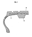
- Fig. 1 is a cross-sectional view of a pneumatic tire 10 on which an electronic-device housing apparatus support 12 constituting the pneumatic-tire-use electronic device fixing system according to the present embodiment is provided, the cross-sectional view being taken in a widthwise direction of a tread thereof.
- the pneumatic-tire-use electronic device fixing system is constituted of an electronic-device housing apparatus 30 and a lock pin 50, both of which will be described later, in addition to the electronic-device housing apparatus support 12.
- a pneumatic-tire-use electronic device corresponds to, for example: a sensor which measures an internal pressure, an internal temperature, and the like of the pneumatic tire 10, and transmits a result of the measurement to a vehicle via radio communications; an IC chip storing, for example, information on management by a manufacturer of the pneumatic tire; or the like.
- an inner liner 11 which is a rubber layer preventing penetration of pressurized air filled in the pneumatic tire 10 is provided.
- the electronic-device housing apparatus support 12 which supports the later described electronic-device housing apparatus 30 is provided on a central portion of a back side of the tread.
- the electronic-device housing apparatus support 12 is provided inside the pneumatic tire 10 inward of the inner liner 11. That is, the electronic-device housing apparatus support 12 is covered with the inner liner 11.
- Fig. 2 is a partially transparent front elevational view of the pneumatic tire 10 according to the present invention.
- the electronic-device housing apparatus supports 12 are provided respectively in four locations with substantially regular intervals.
- locations for the electronic-device housing apparatus supports 12 are not limited to four locations, and may be, for example, two locations, or eight locations. Additionally, in view of securing balance of the pneumatic tire when the pneumatic tire is rotating, it is preferable that distances between adjacent two of the respective electronic-device housing apparatus supports 12 on the circumference of the inner surface of the pneumatic tire 10 be equal.
- Fig. 3A is a perspective view of the electronic-device housing apparatus 30 according to the present embodiment.
- the electronic-device housing apparatus 30 includes an electronic-device housing portion 31, and an engaging convex portion 32.
- the electronic-device housing portion 31 houses an electronic device, such as: a sensor, which measures an internal pressure and an internal temperature of the pneumatic tire 10, and which transmits a result of the measurement to a vehicle via radio communications; or an IC chip which stores information on management by a manufacturer of the pneumatic tire, and the like. Note that a volume of the electronic-device housing portion 31 can be changed as appropriate in accordance with a size of the electronic device intended to be housed therein.
- the engaging convex portion 32 is formed in a convex shape, and is configured to be inserted into an engaging concave portion 12sh (refer to Fig. 4 ) provided in the electronic-device housing apparatus support 12. Additionally, projections 32a (first pullout suppression means) which suppress pullout from the engaging concave portion 12sh are provided on a surface of the engaging convex portion 32, whereby zigzag regions are formed on the engaging convex portion 32.
- each of the projections 32a has a shape which forms an acute angle to a direction in which the engaging convex portion 32 is pulled out.
- the engaging convex portion 32 i.e., the electronic-device housing apparatus 30 is configured not to be easily pulled out from the engaging concave portion 12sh although the engaging convex portion 32 on which the projections 32a are provided is configured to be easily inserted into the engaging concave portion 12sh (refer to Figs. 3A , 5B and 5C ).
- the engaging convex portion 32 includes an insertion hole 32b (a first insertion hole).
- the later described lock pin 50 is inserted into the insertion hole 32b.
- the same rubber-based material as the one used for the electronic-device housing apparatus support 12 can be used as a material for the engaging convex portion 32.
- Fig. 3B is a perspective view of the lock pin 50 according to the present embodiment.
- the lock pin 50 includes a tapering end portion 51, a shaft portion 52, and a locking portion 53.
- the lock pin 50 is inserted into an insertion hole 12fh (refer to Fig. 4 ) and the insertion hole 32b which have been made to communicate with each other by having the electronic-device housing apparatus 30 (the engaging convex portion 32) inserted into the electronic-device housing apparatus support 12 (the engaging concave portion 12sh).
- the tapering end portion 51 While having a front end tapering, the tapering end portion 51 has a rear end, which abuts the shaft portion 52, having a width wider than a diameter of the shaft portion 52. Additionally, diameters of the insertion hole 12fh and the insertion hole 32b are substantially equal to the diameter of the shaft portion 52. That is, the lock pin 50 has a structure which makes it unable to be pulled out once it is inserted into the insertion hole 12fh and the insertion hole 32b.
- the locking portion 53 is configured to lock the shaft portion 52 into which the insertion hole 12fh and the insertion hole 32b, and thereby prevent the shaft portion 52 from coming out of the insertion hole 12fh and the insertion hole 32b.
- plastic can be used as a material for the lock pin 50.
- Fig. 4 is a perspective view of the electronic-device housing apparatus support 12 according to the present embodiment. As shown in this drawing, the electronic-device housing apparatus support 12 has a "pedestal"-like shape formed in a truncated cone.
- the engaging concave portion 12sh is formed in a concave shape, and is configured to have the engaging convex portion 32, which is provided to the electronic-device housing apparatus 30, inserted therein.
- the electronic-device housing apparatus support 12 includes the insertion hole 12fh (a second insertion hole) communicating with the insertion hole 32b provided in the engaging convex portion 32.
- the lock pin 50 is inserted into the insertion hole 12fh as described above.
- the electronic-device housing apparatus support 12 is provided inside the pneumatic tire 10 inward of the inner liner 11, and is formed of a rubber body in the present embodiment. Note that the electronic-device housing apparatus support 12 may be formed of the inner liner 11 itself.
- the electronic-device housing apparatus support 12 is provided on the pneumatic tire 10 in steps of molding and vulcanizing the pneumatic tire 10.
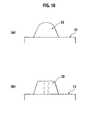
- Figs. 10A and 10B are explanatory diagrams respectively for explaining states where the electronic-device housing apparatus support 12 is provided on the pneumatic tire 10 in the steps of molding and vulcanizing the pneumatic tire 10.
- Fig. 10A is a cross-sectional view of the electronic-device housing apparatus support 12, the cross-sectional view showing a state where the rubber body constituting the electronic-device housing apparatus support 12 is provided, in the step of molding the pneumatic tire 10, inside the pneumatic tire 10 in a radial direction thereof inward of the inner liner 11.
- Fig. 10B is a cross-sectional view of the electronic-device housing apparatus support 12 after the pneumatic tire 10 has been vulcanized. As shown in this Fig. 10B , the engaging concave portion 12sh is provided in the step of vulcanizing the pneumatic tire 10.
- FIGs. 5A to 5C a method of fixing an electronic device to a pneumatic tire by use of the above described pneumatic-tire-use electronic-device fixing system will be described.
- Fig. 5A shows a plan view of the electronic-device housing apparatus support 12. As shown in this Fig. 5A , the engaging concave portion 12sh is provided substantially in the center of the electronic-device housing apparatus support 12.
- the insertion hole 12fh penetrate the electronic-device housing apparatus support 12 in a manner passing through the center of the electronic-device housing apparatus support 12.
- Fig. 5B shows a side view of the electronic-device housing apparatus support 12 when viewed in a direction of an arrow A shown in Fig. 5A . Additionally, Fig. 5B shows a state where, while the electronic-device housing apparatus 30 is being inserted into the engaging concave portion 12sh, the lock pin 50 is being inserted into the insertion hole 12fh.
- engaging grooves 12g (second pullout suppression means) engaging with the respective projections 32a are provided on an inner surface of the engaging concave portion 12sh, whereby zigzag regions are formed on the engaging concave portion 12sh.
- the lock pin 50 is inserted into both of the insertion hole 12fh provided in the electronic-device housing apparatus support 12, and the insertion hole 32b provided in the engaging convex portion 32 of the electronic-device housing apparatus 30.
- Fig. 5C shows a side view of the electronic-device housing apparatus support 12 when viewed in a direction of an arrow B shown in Fig. 5A . Additionally, Fig. 5C shows a state where, while the electronic-device housing apparatus 30 is being inserted into the engaging concave portion 12sh, the lock pin 50 is being inserted into the insertion hole 12fh.
- the second pullout suppression means (the engaging grooves 12g) for engaging with the first pullout suppression means (the projections 32a) provided on the electronic-device housing apparatus 30 is provided on at least a part of the surface of the engaging concave portion 12sh of the electronic-device housing apparatus support 12, whereby the electronic-device housing apparatus 30 can be securely fixed to the pneumatic tire 10.
- the electronic-device housing apparatus support 12 provided on the inner surface of the pneumatic tire 10 can be formed in a "pedestal"-like shape, not a projecting shape, the "pedestal" -like shape having an increased contact area with the inner surface of the pneumatic tire 10.
- the lock pin 50 is inserted into both of the insertion hole 32b provided in the electronic-device housing apparatus 30, and the insertion hole 12fh provided in the electronic-device housing apparatus support 12, whereby the electronic-device housing apparatus 30 and the electronic-device housing apparatus support 12 can be more securely fixed to each other.
- the electronic-device housing apparatus support 12 is a rubber body provided inside the pneumatic tire 10 inward of the inner liner 11, the electronic-device housing apparatus support 12 can be provided on the pneumatic tire 10 in the steps of molding and vulcanizing the pneumatic tire 10. For this reason, it is possible to avoid work of additionally sticking the electronic-device housing apparatus support 12 after manufacturing the pneumatic tire 10.
- the electronic-device housing apparatus support 12 and the pneumatic tire 10 are integrally molded in the steps of molding and vulcanizing the pneumatic tire 10, the electronic-device housing apparatus support 12 can be prevented from coming unstuck from the inner surface of the pneumatic tire 10 while sufficient strength of the electronic-device housing apparatus support 12 can be secured.
- FIG. 6 is a perspective view of an electronic-device housing apparatus 40 according to a modified example of the present invention.
- parts different from the foregoing pneumatic-tire-use electronic-device fixing system according to the present invention will be mainly described.
- the electronic-device housing apparatus 40 includes an electronic-device housing portion 41, and an engaging convex portion 42.
- the electronic-device housing portion 41 houses an electronic device such as: a sensor which measures an internal pressure and an internal temperature of the pneumatic tire 10, and which transmits a result of the measurement to a vehicle via radio communications; or an IC chip, which stores information on management by a manufacturer of the pneumatic tire, and the like.
- an electronic device such as: a sensor which measures an internal pressure and an internal temperature of the pneumatic tire 10, and which transmits a result of the measurement to a vehicle via radio communications; or an IC chip, which stores information on management by a manufacturer of the pneumatic tire, and the like.
- the engaging convex portion 42 is formed in a convex shape, and is configured to be inserted into an engaging concave portion 13sh (refer to Fig. 7 ) provided in a later described electronic-device housing apparatus support 13.
- projections 42a which suppress pullout from the engaging concave portion 13sh are provided on a surface of the engaging convex portion 42.
- each of the projections 42a has a shape which forms an acute angle to a direction in which the engaging convex portion 42 is pulled out.
- the engaging convex portion 42 i.e., the electronic-device housing apparatus 40 is configured not to be easily pulled out from the engaging concave portion 13sh although the engaging convex portion 42 on which the projections 42a are provided is configured to be easily inserted into the engaging concave portion 13sh (refer to Figs. 6 and 8B ).
- the engaging convex portion 42 includes an insertion hole 42b (a first insertion hole). The above described lock pin 50 is inserted into the insertion hole 42b.
- Fig. 7 is a perspective view of the electronic-device housing apparatus support 13 according to the modified example of the present invention. As shown in this drawing, the electronic-device housing apparatus support 13 has a "pedestal"-like shape formed in a truncated pyramid.
- the engaging concave portion 13sh is formed in a concave shape, and is configured to have the engaging convex portion 42, which is provided in the electronic-device housing apparatus 40, inserted therein.
- the electronic-device housing apparatus support 13 includes an insertion hole 13fh (a second insertion hole) communicating with the insertion hole 42b provided in the engaging convex portion 42.
- the lock pin 50 is inserted into the insertion hole 13fh as described above.
- Figs. 8A to 8C are explanatory diagrams for explaining a method of fixing the electronic device to the pneumatic tire 10 by use of the electronic-device housing apparatus support 13, the electronic-device housing apparatus 40 and the lock pin 50, which have been described above.
- Figs. 8A to 8C are the substantially same as the method, which is shown in Figs. 5A to 5C , of fixing the electronic device to the pneumatic tire 10 by use of the electronic-device housing apparatus support 12, the electronic-device housing apparatus 30 and the lock pin 50 according to the embodiment of the present invention.
- the engaging grooves 13g (second pullout suppressing mean) engaging with the projections 42a are provided on a surface of the engaging concave portion 13sh.
- Fig. 9A is a side view of an electronic-device housing apparatus support 12A according to another modified example of the present invention. Additionally, Fig. 9B is a plan view of the electronic-device housing apparatus support 12A.
- the electronic-device housing apparatus support 12A has the similar external shape to that of the electronic-device housing apparatus support 12.
- a peripheral portion of an engaging concave portion 12Ash of the electronic-device housing apparatus support 12A is formed of a rigid body more rigid than a rubber body forming a part of the electronic-device housing apparatus support 12A other than the aforementioned periphery.
- the periphery of the engaging concave portion 12Ash is formed of a plastic member 12p, which is more rigid than the rubber body.
- the plastic member 12p has a shape of a truncated cone in which a top-portion circumference 12pt is shorter than a base-portion circumference 12pb.
- the peripheral portion of the engaging concave portion of the electronic-device housing apparatus support 12A is formed of the rigid body more rigid than the rubber, whereby the engaging convex portion 32 of the electronic-device housing apparatus 30 can be more surely fixed while excessive stress is prevented from being applied to the inner line 11 neighboring the engaging concave portion 12Ash.
- FIG. 11 is a perspective view of an electronic-device housing apparatus 60 according to Modified Example 1 shown in Fig. 6 .
- the electronic-device housing apparatus 60 includes an electronic-device housing portion 61 and an engaging convex portion 62.
- the electronic-device housing portion 61 houses an electronic device such as: a sensor, which measures an internal pressure and an internal temperature of the pneumatic tire 10, and which transmits a result of the measurement to a vehicle via radio communications; or an IC chip which stores information on management by a manufacturer of the pneumatic tire, and the like.
- the engaging convex portion 62 is formed in a convex shape, and is configured to be inserted into an engaging concave portion provided in an electronic-device housing apparatus support (not illustrated).
- notches 52a which suppress pullout from the engaging concave portion of the electronic-device housing apparatus support are provided on a surface of the engaging convex portion 62.
- the engaging convex portion 62 includes an insertion hole 62b (a first insertion hole).
- the lock pin 50 is inserted into the insertion hole 62b.
- the pneumatic-tire-use electronic-device fixing system is useful in techniques of manufacturing pneumatic-tire-use electronic devices because it makes it possible to securely fix a pneumatic-tire-use electronic device while making it possible to suppress breakage of a fixing portion for fixing the pneumatic-tire-use electronic device.
Claims (9)
- System zur Befestigung einer elektronischen Vorrichtung für einen Luftreifen für das Befestigen einer elektronischen Vorrichtung, die an einen Luftreifen (10) montiert wird, wobei das System zur Befestigung einer elektronischen Vorrichtung für einen Luftreifen aufweist:eine Aufnahmeeinrichtung (30, 40, 60) für die elektronische Vorrichtung, die die elektronische Vorrichtung aufnimmt, und die einen konvexen Eingriffsabschnitt (32, 42, 62) umfasst, der konvex ist; undeine Halterung (12, 13, 12A) für die Aufnahmeeinrichtung für die elektronische Vorrichtung, die auf einer Innenfläche des Luftreifens bereitgestellt wird, und die einen konkaven Eingriffsabschnitt (12sh, 13sh, 12Ash, 12p) umfasst, der konkav ist, wobei:mindestens ein Teil einer Fläche des konvexen Eingriffsabschnittes einen ersten Zickzackbereich umfasst, der in einer Zickzackform ausgebildet ist;mindestens ein Teil einer Fläche des konkaven Eingriffsabschnittes einen zweiten Zickzackbereich umfasst, der in einer Zickzackform ausgebildet ist, und wobei der zweite Zickzackbereich mit dem ersten Zickzackbereich in Eingriff kommt; undder erste Zickzackbereich Folgendes bildet: einen geneigten Abschnitt, der sich in einer Richtung verjüngt, in der der konvexe Eingriffsabschnitt in den konkaven Eingriffsabschnitt eingesetzt wird; und einen Abschnitt zur Unterdrückung des Herausziehens, der sich bis zum geneigten Abschnitt fortsetzt und unter einem spitzen Winkel zu einer Richtung verläuft, in der der konvexe Eingriffsabschnitt aus dem konkaven Eingriffsabschnitt herausgezogen wird, und wobei:der konvexe Eingriffsabschnitt ein erstes Einsetzloch (32b, 42b, 62b) umfasst;der konkave Eingriffsabschnitt ein zweites Einsetzloch (12fh) umfasst, das mit dem ersten Einsetzloch in Verbindung steht;das System zur Befestigung einer elektronischen Vorrichtung für einen Luftreifen außerdem einen Sperrstift (50) aufweist, der in das erste und zweite Einsetzloch eingesetzt wird, die so ausgeführt wurden, dass sie miteinander in Verbindung stehen.
- System zur Befestigung einer elektronischen Vorrichtung für einen Luftreifen nach Anspruch 1, bei dem die Halterung für die Aufnahmeeinrichtung für die elektronische Vorrichtung ein Gummikörper ist, der innerhalb des Luftreifens nach innen von einem Innerliner (11) des Luftreifens bereitgestellt wird.
- System zur Befestigung einer elektronischen Vorrichtung für einen Luftreifen nach einem der Ansprüche 1 oder 2, bei dem die Halterung für die Aufnahmeeinrichtung für die elektronische Vorrichtung beim Luftreifen bei den Schritten des Formens und Vulkanisierens des Luftreifens bereitgestellt wird.
- Luftreifen (10), der eine Halterung (12, 13, 12A) für die Aufnahmeeinrichtung für die elektronische Vorrichtung aufweist, die eine Aufnahmeeinrichtung (30, 40, 60) für die elektronische Vorrichtung mit einem konvexen Eingriffsabschnitt (32, 42, 62) hält, der konvex ist, wobei:die Halterung für die Aufnahmeeinrichtung für die elektronische Vorrichtung auf einer Innenfläche des Luftreifens bereitgestellt wird und einen konkaven Eingriffsabschnitt (12sh, 13sh, 12Ash, 12p) umfasst, der konkav ist;mindestens ein Teil einer Fläche des konkaven Eingriffsabschnittes einen Zickzackbereich umfasst, der in einer Zickzackform ausgebildet ist, wobei der Zickzackbereich mit dem konvexen Eingriffsabschnitt in Eingriff kommt; undder Zickzackbereich Folgendes bildet: einen geneigten Abschnitt, der sich in einer Richtung verjüngt, in der der konvexe Eingriffsabschnitt in den konkaven Eingriffsabschnitt eingesetzt wird; und einen Abschnitt zur Unterdrückung des Herausziehens, der sich bis zum geneigten Abschnitt fortsetzt und unter einem spitzen Winkel zu einer Richtung verläuft, in der der konvexe Eingriffsabschnitt aus dem konkaven Eingriffsabschnitt herausgezogen wird, und wobei:der konvexe Eingriffsabschnitt ein erstes Einsetzloch (32b, 42b, 62b) umfasst;der konkave Eingriffsabschnitt ein zweites Einsetzloch (12fh) umfasst, das mit dem ersten Einsetzloch in Verbindung steht; unddie Aufnahmeeinrichtung für die elektronische Vorrichtung mittels eines Sperrstiftes (50) befestigt wird, der in das erste und zweite Einsetzloch eingesetzt wird, die so ausgeführt wurden, dass sie miteinander in Verbindung stehen.
- Luftreifen nach Anspruch 4, bei dem die Halterung für die Aufnahmeeinrichtung für die elektronische Vorrichtung ein Gummikörper ist, der innerhalb des Luftreifens nach innen von einem Innerliner (11) des Luftreifens bereitgestellt wird.
- Luftreifen nach Anspruch 4 oder 5, bei dem die Halterung für die Aufnahmeeinrichtung für die elektronische Vorrichtung beim Luftreifen bei den Schritten des Formens und Vulkanisierens des Luftreifens bereitgestellt wird.
- Aufnahmeeinrichtung (30, 40, 60) für die elektronische Vorrichtung, die von einer Halterung (12, 13, 12A) für die Aufnahmeeinrichtung für die elektronische Vorrichtung gehalten wird, die einen konkaven Eingriffsabschnitt (12sh, 13sh, 12Ash, 12p) umfasst, der an einem Luftreifen vorhanden ist, und die eine elektronische Vorrichtung aufnimmt, die am Luftreifen montiert wird, wobei die Aufnahmeeinrichtung für die elektronische Vorrichtung einen konvexen Eingriffsabschnitt (32, 42, 62) aufweist, der konvex ist, wobei:mindestens ein Teil einer Fläche des konvexen Eingriffsabschnittes einen Zickzackbereich umfasst, der in einer Zickzackform ausgebildet ist; undder Zickzackbereich Folgendes bildet: einen geneigten Abschnitt, der sich in einer Richtung verjüngt, in der der konvexe Eingriffsabschnitt in den konkaven Eingriffsabschnitt eingesetzt wird; und einen Abschnitt zur Unterdrückung des Herausziehens, der sich bis zum geneigten Abschnitt fortsetzt und unter einem spitzen Winkel zu einer Richtung verläuft, in der der konvexe Eingriffsabschnitt aus dem konkaven Eingriffsabschnitt herausgezogen wird, und wobei:der konvexe Eingriffsabschnitt ein erstes Einsetzloch (32b, 42b, 62b) umfasst;der konkave Eingriffsabschnitt ein zweites Einsetzloch (12fh) umfasst, das mit dem ersten Einsetzloch in Verbindung steht; unddie Aufnahmeeinrichtung für die elektronische Vorrichtung mittels eines Sperrstiftes (50) befestigt wird, der in das erste und zweite Einsetzloch eingesetzt wird, die so ausgeführt wurden, dass sie miteinander in Verbindung stehen.
- System zur Befestigung einer elektronischen Vorrichtung für einen Luftreifen nach einem der Ansprüche 1 bis 3, bei dem:der erste Zickzackbereich und der zweite Zickzackbereich miteinander in Eingriff kommen, indem der konvexe Eingriffsabschnitt in den konkaven Eingriffsabschnitt mit Presspassung gebracht wird.
- Luftreifen nach einem der Ansprüche 4 bis 6, bei dem:mindestens ein Teil der Fläche des konvexen Eingriffsabschnittes in einer Zickzackform ausgebildet ist; und wobei der Zickzackbereich und der konvexe Eingriffsabschnitt miteinander in Eingriff kommen, indem der konvexe Eingriffsabschnitt in den konkaven Eingriffsabschnitt mit Presspassung gebracht wird.
Applications Claiming Priority (2)
| Application Number | Priority Date | Filing Date | Title |
|---|---|---|---|
| JP2004058063 | 2004-03-02 | ||
| PCT/JP2005/003478 WO2005082644A1 (ja) | 2004-03-02 | 2005-03-02 | 空気入りタイヤ用電子デバイス固定システム、空気入りタイヤ及び電子デバイス収容装置 |
Publications (3)
| Publication Number | Publication Date |
|---|---|
| EP1721760A1 EP1721760A1 (de) | 2006-11-15 |
| EP1721760A4 EP1721760A4 (de) | 2010-04-28 |
| EP1721760B1 true EP1721760B1 (de) | 2011-07-13 |
Family
ID=34909090
Family Applications (1)
| Application Number | Title | Priority Date | Filing Date |
|---|---|---|---|
| EP05719793A Expired - Fee Related EP1721760B1 (de) | 2004-03-02 | 2005-03-02 | System zur befestigung einer elektronischen vorrichtung für einen luftreifen, luftreifen und lagerungseinrichtung für elektronische vorrichtung |
Country Status (4)
| Country | Link |
|---|---|
| US (1) | US7325448B2 (de) |
| EP (1) | EP1721760B1 (de) |
| JP (1) | JP4573831B2 (de) |
| WO (1) | WO2005082644A1 (de) |
Families Citing this family (18)
| Publication number | Priority date | Publication date | Assignee | Title |
|---|---|---|---|---|
| FR2922486B1 (fr) * | 2007-10-23 | 2009-12-11 | Michelin Soc Tech | Ensemble d'un pneumatique et d'un organe souple |
| FR2922487B1 (fr) | 2007-10-23 | 2009-12-11 | Michelin Soc Tech | Organe formant support pour un dispositif et pneumatique comprenant un tel organe |
| DE102009006707A1 (de) * | 2009-01-29 | 2010-08-05 | Bayerische Motoren Werke Aktiengesellschaft | Reifen eines Fahrzeugs mit einem Sensorelement |
| FR2962374B1 (fr) * | 2010-07-08 | 2012-09-07 | Michelin Soc Tech | Pneumatique de vehicule comprenant un transpondeur a radiofrequence |
| JP2012025319A (ja) * | 2010-07-27 | 2012-02-09 | Yokohama Rubber Co Ltd:The | 空気入りタイヤおよびその製造方法 |
| US9656434B2 (en) | 2010-11-30 | 2017-05-23 | The Good Year Tire & Rubber Company | Measuring tire pressure in a tire mold |
| JP2013035463A (ja) * | 2011-08-09 | 2013-02-21 | Bridgestone Corp | 空気入りタイヤ |
| US8596117B2 (en) | 2011-10-03 | 2013-12-03 | Bridgestone Americas Tire Operations, Llc | Attachment patch for mounting various devices |
| CN104169106B (zh) * | 2012-03-15 | 2017-10-27 | 普利司通美国轮胎运营有限责任公司 | 胎腔气流特征 |
| US20140130357A1 (en) * | 2012-11-09 | 2014-05-15 | The Goodyear Tire & Rubber Company | Securing to a pneumatic tire |
| US20140174621A1 (en) * | 2012-12-20 | 2014-06-26 | The Goodyear Tire & Rubber Company | Pneumatic tire with built in fastener system |
| JP5466777B1 (ja) * | 2013-04-18 | 2014-04-09 | 株式会社ブリヂストン | タイヤの計測器具およびタイヤの計測方法 |
| EP3242805B1 (de) | 2014-12-19 | 2019-11-20 | Bridgestone Americas Tire Operations, LLC | Befestigungspatch zur montage von vorrichtungen |
| BR112017013500A2 (pt) * | 2014-12-30 | 2018-03-06 | Bridgestone Americas Tire Operations Llc | conjunto para fixação de um pacote de circuitos eletrônicos a um pneu |
| BR112017013459A2 (pt) * | 2014-12-30 | 2018-01-09 | Bridgestone Americas Tire Operations Llc | artigo de borracha incluindo um mecanismo de fixação de circuito eletrônico |
| US20170355238A1 (en) * | 2014-12-30 | 2017-12-14 | Bridgestone Americas Tire Operations, Llc | Rubber article including electronics device fastener |
| FR3063040B1 (fr) * | 2017-02-17 | 2021-06-18 | Michelin & Cie | Dispositif de fixation a une enveloppe pneumatique d'un organe electronique. |
| EP3543042B1 (de) * | 2018-03-19 | 2020-04-29 | Nokian Renkaat Oyj | Reifen mit einem modul |
Family Cites Families (11)
| Publication number | Priority date | Publication date | Assignee | Title |
|---|---|---|---|---|
| US3872424A (en) * | 1973-10-12 | 1975-03-18 | Goodyear Tire & Rubber | Apparatus and method for transmitting auxiliary signals on existing vehicle wiring |
| US4052696A (en) * | 1976-03-01 | 1977-10-04 | The Goodyear Tire & Rubber Company | Tire condition monitor |
| US4099157A (en) * | 1976-12-22 | 1978-07-04 | The Goodyear Tire & Rubber Company | Single wire power/signal system for vehicle auxiliary devices |
| US5218861A (en) * | 1991-03-27 | 1993-06-15 | The Goodyear Tire & Rubber Company | Pneumatic tire having an integrated circuit transponder and pressure transducer |
| FR2766563A1 (fr) * | 1997-07-23 | 1999-01-29 | Michelin & Cie | Dispositif de surveillance des sollicitations subies par un pneumatique |
| US7009506B2 (en) * | 1998-02-10 | 2006-03-07 | Bridgestone Firestone North American Tire, Llc | Electronic monitoring device and patch assembly |
| US6030478A (en) * | 1998-02-10 | 2000-02-29 | Bridgestone/Firestone, Inc. | Method and apparatus for removably inserting an electric tire tag into a tire |
| JP2002502765A (ja) * | 1998-02-12 | 2002-01-29 | ミシュラン ルシェルシェ エ テクニク ソシエテ アノニム | タイヤ用電子パッケージの取付け手段 |
| DE69916115T2 (de) * | 1998-08-03 | 2009-10-01 | The Goodyear Tire & Rubber Co., Akron | Montage von transpondern in luftreifen |
| EP1235696B1 (de) * | 1999-11-24 | 2009-11-04 | Michelin Recherche Et Technique S.A. | Überwachter fahrzeugreifen sowie halter für überwachungsvorrichtung |
| JP4612247B2 (ja) * | 2001-08-09 | 2011-01-12 | 住友ゴム工業株式会社 | トレッド変形測定手段を備えたタイヤおよびタイヤトレッドの変形検出方法 |
-
2005
- 2005-03-02 JP JP2006510531A patent/JP4573831B2/ja not_active Expired - Fee Related
- 2005-03-02 WO PCT/JP2005/003478 patent/WO2005082644A1/ja active Application Filing
- 2005-03-02 EP EP05719793A patent/EP1721760B1/de not_active Expired - Fee Related
- 2005-03-02 US US10/591,590 patent/US7325448B2/en not_active Expired - Fee Related
Also Published As
| Publication number | Publication date |
|---|---|
| JP4573831B2 (ja) | 2010-11-04 |
| WO2005082644A1 (ja) | 2005-09-09 |
| US7325448B2 (en) | 2008-02-05 |
| US20070169865A1 (en) | 2007-07-26 |
| JPWO2005082644A1 (ja) | 2007-08-02 |
| EP1721760A4 (de) | 2010-04-28 |
| EP1721760A1 (de) | 2006-11-15 |
Similar Documents
| Publication | Publication Date | Title |
|---|---|---|
| EP1721760B1 (de) | System zur befestigung einer elektronischen vorrichtung für einen luftreifen, luftreifen und lagerungseinrichtung für elektronische vorrichtung | |
| EP2460673B1 (de) | Luftreifen und Verfahren zur Montage eines Transponders an den Luftreifen | |
| US11607917B2 (en) | Tire sensor installation structure and manufacturing method thereof | |
| CA2307072C (en) | Dipole antenna for tire tag | |
| EP3582980B1 (de) | Vorrichtung zur befestigung eines elektronischen elements an einen luftreifen | |
| EP3659819B1 (de) | Luftreifen | |
| WO2012160896A1 (ja) | 空気入りタイヤ | |
| US20080295933A1 (en) | Tire Tread Support Element Comprising A Recess For An Electronic Module, And An Electronic Module Adapted Thereto | |
| WO2018173640A1 (ja) | 機能部品取付台座 | |
| US8226783B2 (en) | Pneumatic tire and method of mounting transponder to pneumatic tire | |
| JP5651534B2 (ja) | 取付構造体 | |
| US10639948B2 (en) | Assembly for attaching an electronics package to a tire | |
| KR200489733Y1 (ko) | 센서결합부가 형성된 타이어 | |
| JP2006240598A (ja) | モジュール取付用パッチ、及び、このモジュール取付用パッチを有する空気入りタイヤ | |
| CA3109996C (en) | Tpms transmitter fixing structure and assembling structure | |
| JP5647573B2 (ja) | 取付構造体 | |
| JP3809394B2 (ja) | 模型用車輪 | |
| JP4561288B2 (ja) | 空気入りタイヤおよび空気入りタイヤへのトランスポンダの取り付け方法 | |
| JP2006015909A (ja) | タイヤ内電子デバイス固定装置 | |
| GB2357474A (en) | Vehicle inner tube having multiple air cells and breakers | |
| JP2009126229A (ja) | タイヤ用リム、およびタイヤ用ホイール |
Legal Events
| Date | Code | Title | Description |
|---|---|---|---|
| PUAI | Public reference made under article 153(3) epc to a published international application that has entered the european phase |
Free format text: ORIGINAL CODE: 0009012 |
|
| 17P | Request for examination filed |
Effective date: 20060908 |
|
| AK | Designated contracting states |
Kind code of ref document: A1 Designated state(s): DE FR IT |
|
| DAX | Request for extension of the european patent (deleted) | ||
| RBV | Designated contracting states (corrected) |
Designated state(s): DE FR IT |
|
| A4 | Supplementary search report drawn up and despatched |
Effective date: 20100329 |
|
| RIC1 | Information provided on ipc code assigned before grant |
Ipc: B60C 23/04 20060101ALI20100322BHEP Ipc: B60C 19/00 20060101AFI20050914BHEP |
|
| 17Q | First examination report despatched |
Effective date: 20100906 |
|
| RIC1 | Information provided on ipc code assigned before grant |
Ipc: B60C 19/00 20060101AFI20101130BHEP Ipc: B60C 23/04 20060101ALI20101130BHEP |
|
| GRAP | Despatch of communication of intention to grant a patent |
Free format text: ORIGINAL CODE: EPIDOSNIGR1 |
|
| GRAS | Grant fee paid |
Free format text: ORIGINAL CODE: EPIDOSNIGR3 |
|
| GRAA | (expected) grant |
Free format text: ORIGINAL CODE: 0009210 |
|
| AK | Designated contracting states |
Kind code of ref document: B1 Designated state(s): DE FR IT |
|
| REG | Reference to a national code |
Ref country code: DE Ref legal event code: R096 Ref document number: 602005028972 Country of ref document: DE Effective date: 20110908 |
|
| PLBE | No opposition filed within time limit |
Free format text: ORIGINAL CODE: 0009261 |
|
| STAA | Information on the status of an ep patent application or granted ep patent |
Free format text: STATUS: NO OPPOSITION FILED WITHIN TIME LIMIT |
|
| 26N | No opposition filed |
Effective date: 20120416 |
|
| PGFP | Annual fee paid to national office [announced via postgrant information from national office to epo] |
Ref country code: IT Payment date: 20120315 Year of fee payment: 8 |
|
| REG | Reference to a national code |
Ref country code: DE Ref legal event code: R097 Ref document number: 602005028972 Country of ref document: DE Effective date: 20120416 |
|
| PGFP | Annual fee paid to national office [announced via postgrant information from national office to epo] |
Ref country code: FR Payment date: 20130325 Year of fee payment: 9 Ref country code: DE Payment date: 20130227 Year of fee payment: 9 |
|
| REG | Reference to a national code |
Ref country code: DE Ref legal event code: R119 Ref document number: 602005028972 Country of ref document: DE |
|
| REG | Reference to a national code |
Ref country code: FR Ref legal event code: ST Effective date: 20141128 |
|
| REG | Reference to a national code |
Ref country code: DE Ref legal event code: R119 Ref document number: 602005028972 Country of ref document: DE Effective date: 20141001 |
|
| PG25 | Lapsed in a contracting state [announced via postgrant information from national office to epo] |
Ref country code: DE Free format text: LAPSE BECAUSE OF NON-PAYMENT OF DUE FEES Effective date: 20141001 Ref country code: FR Free format text: LAPSE BECAUSE OF NON-PAYMENT OF DUE FEES Effective date: 20140331 |
|
| PG25 | Lapsed in a contracting state [announced via postgrant information from national office to epo] |
Ref country code: IT Free format text: LAPSE BECAUSE OF NON-PAYMENT OF DUE FEES Effective date: 20140302 |