EP1721687A1 - Method for casting a metal piece with the lost foam technique - Google Patents
Method for casting a metal piece with the lost foam technique Download PDFInfo
- Publication number
- EP1721687A1 EP1721687A1 EP05425322A EP05425322A EP1721687A1 EP 1721687 A1 EP1721687 A1 EP 1721687A1 EP 05425322 A EP05425322 A EP 05425322A EP 05425322 A EP05425322 A EP 05425322A EP 1721687 A1 EP1721687 A1 EP 1721687A1
- Authority
- EP
- European Patent Office
- Prior art keywords
- portions
- pattern
- casting
- metal
- gates
- Prior art date
- Legal status (The legal status is an assumption and is not a legal conclusion. Google has not performed a legal analysis and makes no representation as to the accuracy of the status listed.)
- Withdrawn
Links
Images


Classifications
-
- B—PERFORMING OPERATIONS; TRANSPORTING
- B22—CASTING; POWDER METALLURGY
- B22C—FOUNDRY MOULDING
- B22C9/00—Moulds or cores; Moulding processes
- B22C9/02—Sand moulds or like moulds for shaped castings
- B22C9/04—Use of lost patterns
- B22C9/046—Use of patterns which are eliminated by the liquid metal in the mould
-
- B—PERFORMING OPERATIONS; TRANSPORTING
- B22—CASTING; POWDER METALLURGY
- B22C—FOUNDRY MOULDING
- B22C7/00—Patterns; Manufacture thereof so far as not provided for in other classes
- B22C7/02—Lost patterns
- B22C7/023—Patterns made from expanded plastic materials
-
- B—PERFORMING OPERATIONS; TRANSPORTING
- B22—CASTING; POWDER METALLURGY
- B22D—CASTING OF METALS; CASTING OF OTHER SUBSTANCES BY THE SAME PROCESSES OR DEVICES
- B22D27/00—Treating the metal in the mould while it is molten or ductile ; Pressure or vacuum casting
- B22D27/04—Influencing the temperature of the metal, e.g. by heating or cooling the mould
Definitions
- the present invention relates to methods for obtaining metal castings, particularly steel castings, through the use of expendable patterns of foamed-plastic material, using the so-called “lost-foam” technique or “expendable-pattern casting” (EPC) technique.
- EPC expendable-pattern casting
- the patterns are coated with one or more layers of refractory paint and placed in a container, which is subsequently filled with sand.
- the liquid metal is poured into the mould and takes the place of the foamed pattern.
- the body of the pattern also incorporates one or more feed channels, which at the moment of casting define the feed channels or sprues of the molten metal.
- Said feed portions are connected to the main body of the pattern by means of one or more in-gates, which are to define, at the moment of casting, inlets for the molten metal within the main body.
- the lost-foam casting technique has rapidly developed in recent years on account of a series of advantages that it offers. With said technique, during the process of casting, the pattern made of foamed-plastic material undergoes thermal degradation (melting, depolymerization, pyrolysis and evolution of liquid and gas fractions) and is progressively replaced by the molten metal.
- the purpose of the present invention is to overcome said drawback.
- the subject of the present invention is a method of the type referred to above, characterized in that there is provided a pattern, the body of which also incorporates auxiliary portions that extend from one or more of the aforesaid feed portions for defining, at the moment of casting, metal portions irradiating heat, which slow down cooling of the portions of the body adjacent thereto.
- prearranged in the pattern are one or more heating portions immediately adjacent to the aforesaid inlet portions.
- the aforesaid heating portions are in the form of plane fins projecting in cantilever fashion from one or more feed portions of the body of the pattern and having free ends situated immediately adjacent to, but set at a distance from, the main body of the pattern.
- the aforesaid fins forming part of the body of the pattern are replaced by molten metal, thus giving rise to metal fins that irradiate heat in an area immediately adjacent to the inlet portions of the pattern.
- the molten metal in the area corresponding to the inlet portions tends to cool and solidify last with respect to all the innermost portions, which are also of greater thickness, of the body of the pattern.
- the inlet portions are always able to supply new molten metal, which fills, during the process of casting, the cavities that are formed within the body of the casting as a result of the shrinkage of the metal as it solidifies.
- a pattern made of foamed-plastic material is provided, designated as a whole by 1 in the drawings.
- the pattern 1 comprises a main body 2, the configuration of which corresponds to that of the finished piece to be obtained.
- the body 1 of foamed-plastic material likewise incorporates a pair of elongated and parallel portions 3 arranged at the two sides of the main body 2 and parallel thereto, which are to define, at the moment of casting, feed portions of the molten metal.
- the feed portions 3 are connected to one another at one end by means of the connection portion 4 and are moreover connected to the main body 2 by means of inlet portions 5 (in-gates).
- in-gates inlet portions 5
- two in-gates are provided, set at a distance from one another, for each feed portion 3.
- the body of the pattern 1 likewise incorporates heating portions 6, which are to define, at the moment of casting, metal portions for irradiation of heat.
- the heating portions 6 are in the form of a pair of plane and parallel fins projecting in cantilever fashion from each feed portion 3, at the two sides of each in-gate 5.
- Each fin 6 has a free end with an edge set at a distance from, but adjacent to, a corresponding surface of the main body 2 of the pattern.
- the pattern 1 illustrated in the drawings is designed to be used in a lost-foam process in a way in itself known.
- the pattern is obtained using any technique for moulding plastic material in a mould provided for said purpose. After obtaining the pattern, the latter is coated with a layer of paint and then sandblasted. At this point the molten metal is cast directly within channels that communicate with the feed portions of the pattern. Said portions degrade thermally and are replaced progressively by the molten metal. The molten metal thus progressively reaches the in-gates and thence replaces the entire pattern made of foamed-plastic material.
- the in-gates 5 are kept hot as a result of the heat irradiated by the fins 6, which in the meantime have been transformed into metal fins.
- the innermost parts of greater thickness of the main body of the casting cool and solidify subsequent to cooling and solidification of the in-gates 5.
- the cavities that tend to be formed within the main body as a result of shrinkage of the metal during solidification are duly filled by further molten metal fed in through the in-gates until a casting of excellent quality is obtained at the moment in which also the in-gates, together with the fins 6, cool and solidify.
- the piece is subjected to the usual operations envisaged in a process of lost-foam casting.
- the main body of the object is separated from the accessory portions defined by the feed portions 3, by the in-gates 5 and by the heating fins 6.
- said accessory parts are separated with an operation of cutting in an area corresponding to the sections of connection to the in-gates 5.
- the piece then undergoes the usual machining operations.
Landscapes
- Engineering & Computer Science (AREA)
- Mechanical Engineering (AREA)
- Molds, Cores, And Manufacturing Methods Thereof (AREA)
Abstract
A method for casting of a metal piece, particularly a piece of steel, using the lost-foam technique envisages the provision of a pattern made of foamed-plastic material, the body of which includes auxiliary portions (6) that are to define, at the moment of casting, metal portions irradiating heat, which slow down cooling and consequent solidification in one or more in-gates (5), through which the molten metal fills the main body of the pattern, so as to prevent said in-gates from solidifying before cooling of the portions of greater thickness of the body of the casting has occurred.
Description
- The present invention relates to methods for obtaining metal castings, particularly steel castings, through the use of expendable patterns of foamed-plastic material, using the so-called "lost-foam" technique or "expendable-pattern casting" (EPC) technique.
- The use of disposable patterns of foamed material for obtaining metal castings was developed and patented by
H.F. Shroyer in 1958 (US Patent N° 2,830,343 ). The idea of using non-bound sand was patented later bySmith, in 1964 (US Patent N° 3,157,924 ). - The patterns are coated with one or more layers of refractory paint and placed in a container, which is subsequently filled with sand. The liquid metal is poured into the mould and takes the place of the foamed pattern. Using the usual technique, in this type of casting process, the body of the pattern also incorporates one or more feed channels, which at the moment of casting define the feed channels or sprues of the molten metal. Said feed portions are connected to the main body of the pattern by means of one or more in-gates, which are to define, at the moment of casting, inlets for the molten metal within the main body.
- The lost-foam casting technique has rapidly developed in recent years on account of a series of advantages that it offers. With said technique, during the process of casting, the pattern made of foamed-plastic material undergoes thermal degradation (melting, depolymerization, pyrolysis and evolution of liquid and gas fractions) and is progressively replaced by the molten metal.
- The aforesaid technique is above all used for making castings of aluminium alloy or light alloy, whilst it finds some difficulty of application to the production of castings made of cast iron or steel. Particularly in the case of steel, given the marked shrinkage of the material during the step of cooling and solidification, there readily occur, in areas corresponding to the larger sections of the casting, porosities due to shrinkage, owing to the fact that the parts of greater thickness are still partially or totally in the molten state when the inlet portions are already solidified. This prevents new molten metal from supplying the cavities that are created following upon shrinkage of the parts of greater thickness when also these solidify.
- The purpose of the present invention is to overcome said drawback.
- In:order to achieve said purpose, the subject of the present invention is a method of the type referred to above, characterized in that there is provided a pattern, the body of which also incorporates auxiliary portions that extend from one or more of the aforesaid feed portions for defining, at the moment of casting, metal portions irradiating heat, which slow down cooling of the portions of the body adjacent thereto.
- Preferably, according to the invention, prearranged in the pattern are one or more heating portions immediately adjacent to the aforesaid inlet portions.
- Once again preferably, the aforesaid heating portions are in the form of plane fins projecting in cantilever fashion from one or more feed portions of the body of the pattern and having free ends situated immediately adjacent to, but set at a distance from, the main body of the pattern.
- Thanks to the aforesaid characteristics, during casting, the aforesaid fins forming part of the body of the pattern are replaced by molten metal, thus giving rise to metal fins that irradiate heat in an area immediately adjacent to the inlet portions of the pattern. As a result of the presence of the radiant fins, the molten metal in the area corresponding to the inlet portions tends to cool and solidify last with respect to all the innermost portions, which are also of greater thickness, of the body of the pattern. In this way, the inlet portions are always able to supply new molten metal, which fills, during the process of casting, the cavities that are formed within the body of the casting as a result of the shrinkage of the metal as it solidifies.
- Further characteristics and advantages of the invention will emerge from the ensuing description with reference to the annexed plate of drawings, which are provided purely by way of non-limiting example and in which:
- Figure 1 is an elevation of the pattern made of foamed-plastic material used in the method according to the invention in order to obtain a steel engine crankshaft;
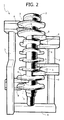
- Figure 2 is a perspective view of the pattern illustrated in Figure 1, taken from the opposite side with respect to that of Figure 1; and
- Figure 3 is a perspective view at an enlarged scale of a detail of the pattern illustrated in Figures 1 and 2.
- In order to obtain an engine crankshaft using the method of the invention, a pattern made of foamed-plastic material is provided, designated as a whole by 1 in the drawings. The
pattern 1 comprises amain body 2, the configuration of which corresponds to that of the finished piece to be obtained. Thebody 1 of foamed-plastic material likewise incorporates a pair of elongated andparallel portions 3 arranged at the two sides of themain body 2 and parallel thereto, which are to define, at the moment of casting, feed portions of the molten metal. Thefeed portions 3 are connected to one another at one end by means of theconnection portion 4 and are moreover connected to themain body 2 by means of inlet portions 5 (in-gates). In the example illustrated, two in-gates are provided, set at a distance from one another, for eachfeed portion 3. - According to the main characteristic of the invention, the body of the
pattern 1 likewise incorporatesheating portions 6, which are to define, at the moment of casting, metal portions for irradiation of heat. - In the preferred embodiment illustrated herein, the
heating portions 6 are in the form of a pair of plane and parallel fins projecting in cantilever fashion from eachfeed portion 3, at the two sides of each in-gate 5. Eachfin 6 has a free end with an edge set at a distance from, but adjacent to, a corresponding surface of themain body 2 of the pattern. - The
pattern 1 illustrated in the drawings is designed to be used in a lost-foam process in a way in itself known. The pattern is obtained using any technique for moulding plastic material in a mould provided for said purpose. After obtaining the pattern, the latter is coated with a layer of paint and then sandblasted. At this point the molten metal is cast directly within channels that communicate with the feed portions of the pattern. Said portions degrade thermally and are replaced progressively by the molten metal. The molten metal thus progressively reaches the in-gates and thence replaces the entire pattern made of foamed-plastic material. During the process of cooling and solidification, the in-gates 5 are kept hot as a result of the heat irradiated by thefins 6, which in the meantime have been transformed into metal fins. In this way, the innermost parts of greater thickness of the main body of the casting cool and solidify subsequent to cooling and solidification of the in-gates 5. In said way, the cavities that tend to be formed within the main body as a result of shrinkage of the metal during solidification are duly filled by further molten metal fed in through the in-gates until a casting of excellent quality is obtained at the moment in which also the in-gates, together with thefins 6, cool and solidify. - At the end of the step of cooling and solidification, the piece is subjected to the usual operations envisaged in a process of lost-foam casting. The main body of the object is separated from the accessory portions defined by the
feed portions 3, by the in-gates 5 and by theheating fins 6. For this purpose, said accessory parts are separated with an operation of cutting in an area corresponding to the sections of connection to the in-gates 5. The piece then undergoes the usual machining operations. - Of course, it is possible to envisage "clusters" of patterns of the type illustrated in the annexed drawings, for casting a number of pieces simultaneously. The shape and arrangement of the
heating portions 6 are of course chosen according to the characteristics of the piece to be obtained. - Of course, without prejudice the principle of the invention, the details of construction and the embodiments may vary widely with respect to what is described and illustrated herein by way of example, without thereby departing from the scope of the present invention.
Claims (5)
- A method for obtaining a casting of metal, particularly of steel, using the lost-foam technique, in which the molten metal is cast on a pattern made of foamed-plastic material, in which the body of the pattern also incorporates one or more feed portions (3, which at the moment of casting define feed channels or sprues for supply of the molten metal, said feed portions (3) being connected to the main body (2) of the pattern via one or more in-gates (5), which are to define at the moment of casting the inlets for the molten metal within the main body,
said method being characterized in that the body (1) of the pattern also incorporates auxiliary portions (6) that extend from one or more feed portions (3) for defining, at the moment of casting, metal portions irradiating heat, which slow down cooling of the portions of the body of the pattern adjacent thereto. - The method according to Claim 1, characterized in that one or more of said auxiliary portions (6) are arranged adjacent to one or more of the aforesaid in-gates (5).
- The method according to Claim 2, characterized in that the aforesaid auxiliary portions (6) are in the form of plane fins projecting in cantilever fashion from one or more feed portions (3) of the body of the pattern.
- The method according to Claim 3, characterized in that one or more fins (6) are provided at the two sides of each in-gate (5).
- The method according to Claim 3, characterized in that each fin (6) has a free end with an edge set at a distance from, but adjacent to, a portion of the surface of the main body of the pattern.
Priority Applications (1)
| Application Number | Priority Date | Filing Date | Title |
|---|---|---|---|
| EP05425322A EP1721687A1 (en) | 2005-05-13 | 2005-05-13 | Method for casting a metal piece with the lost foam technique |
Applications Claiming Priority (1)
| Application Number | Priority Date | Filing Date | Title |
|---|---|---|---|
| EP05425322A EP1721687A1 (en) | 2005-05-13 | 2005-05-13 | Method for casting a metal piece with the lost foam technique |
Publications (1)
| Publication Number | Publication Date |
|---|---|
| EP1721687A1 true EP1721687A1 (en) | 2006-11-15 |
Family
ID=34943195
Family Applications (1)
| Application Number | Title | Priority Date | Filing Date |
|---|---|---|---|
| EP05425322A Withdrawn EP1721687A1 (en) | 2005-05-13 | 2005-05-13 | Method for casting a metal piece with the lost foam technique |
Country Status (1)
| Country | Link |
|---|---|
| EP (1) | EP1721687A1 (en) |
Cited By (4)
| Publication number | Priority date | Publication date | Assignee | Title |
|---|---|---|---|---|
| EP1852198A3 (en) * | 2006-05-01 | 2008-10-22 | GM Global Technology Operations, Inc. | Casting method and mold design for optimization of material properties of a casting |
| CN104493080A (en) * | 2014-11-28 | 2015-04-08 | 柳州市正龙机械制造有限公司 | Technology for preparing model by lost foam casting |
| CN111531132A (en) * | 2020-05-30 | 2020-08-14 | 张明杰 | Transmission crankshaft forming and casting die |
| CN113385638A (en) * | 2021-06-22 | 2021-09-14 | 内蒙古工业大学 | Production process for casting core mould parts based on lost foam technology |
Citations (7)
| Publication number | Priority date | Publication date | Assignee | Title |
|---|---|---|---|---|
| JPS6283414A (en) * | 1985-10-07 | 1987-04-16 | Honda Motor Co Ltd | Casting method of spheroidal graphite cast iron crankshaft material |
| US4736786A (en) * | 1985-12-31 | 1988-04-12 | Deere & Company | Method for improving stength of gasifiable patterns |
| US4766942A (en) * | 1987-12-16 | 1988-08-30 | Ford Motor Company | Evaporative pattern assembly and method of making |
| EP0431770A2 (en) * | 1989-12-04 | 1991-06-12 | General Motors Corporation | Lost-foam Casting of dual alloy engine block |
| US5038847A (en) * | 1988-08-30 | 1991-08-13 | Brunswick Corporation | Evaporable foam pattern for use in casting a crankshaft |
| FR2685229A1 (en) * | 1991-12-20 | 1993-06-25 | Peugeot | Method for consumable- (disposable-) pattern moulding and refrigerating element for implementing this method |
| US6886621B1 (en) * | 2002-08-29 | 2005-05-03 | Brunswick Corp. | Sprue for a lost foam casting system for biasing a directional fill rate from a bottom portion of a metal casting |
-
2005
- 2005-05-13 EP EP05425322A patent/EP1721687A1/en not_active Withdrawn
Patent Citations (7)
| Publication number | Priority date | Publication date | Assignee | Title |
|---|---|---|---|---|
| JPS6283414A (en) * | 1985-10-07 | 1987-04-16 | Honda Motor Co Ltd | Casting method of spheroidal graphite cast iron crankshaft material |
| US4736786A (en) * | 1985-12-31 | 1988-04-12 | Deere & Company | Method for improving stength of gasifiable patterns |
| US4766942A (en) * | 1987-12-16 | 1988-08-30 | Ford Motor Company | Evaporative pattern assembly and method of making |
| US5038847A (en) * | 1988-08-30 | 1991-08-13 | Brunswick Corporation | Evaporable foam pattern for use in casting a crankshaft |
| EP0431770A2 (en) * | 1989-12-04 | 1991-06-12 | General Motors Corporation | Lost-foam Casting of dual alloy engine block |
| FR2685229A1 (en) * | 1991-12-20 | 1993-06-25 | Peugeot | Method for consumable- (disposable-) pattern moulding and refrigerating element for implementing this method |
| US6886621B1 (en) * | 2002-08-29 | 2005-05-03 | Brunswick Corp. | Sprue for a lost foam casting system for biasing a directional fill rate from a bottom portion of a metal casting |
Non-Patent Citations (1)
| Title |
|---|
| PATENT ABSTRACTS OF JAPAN vol. 011, no. 290 (C - 447) 18 September 1987 (1987-09-18) * |
Cited By (5)
| Publication number | Priority date | Publication date | Assignee | Title |
|---|---|---|---|---|
| EP1852198A3 (en) * | 2006-05-01 | 2008-10-22 | GM Global Technology Operations, Inc. | Casting method and mold design for optimization of material properties of a casting |
| CN104493080A (en) * | 2014-11-28 | 2015-04-08 | 柳州市正龙机械制造有限公司 | Technology for preparing model by lost foam casting |
| CN111531132A (en) * | 2020-05-30 | 2020-08-14 | 张明杰 | Transmission crankshaft forming and casting die |
| CN111531132B (en) * | 2020-05-30 | 2021-12-03 | 科佳(长兴)模架制造有限公司 | Transmission crankshaft forming and casting die |
| CN113385638A (en) * | 2021-06-22 | 2021-09-14 | 内蒙古工业大学 | Production process for casting core mould parts based on lost foam technology |
Similar Documents
| Publication | Publication Date | Title |
|---|---|---|
| Kang et al. | Additive manufacturing-driven mold design for castings | |
| US8307882B2 (en) | Casting method | |
| PT1534451E (en) | FOUNDRY PROCESS | |
| JP2017013091A (en) | Wax mold and lost wax casting method | |
| CN101146634A (en) | Method and apparatus for improving heat removal from directionally solidified aluminum castings | |
| US20090133848A1 (en) | One-Piece Lost Mould for Metal Castings and Method for Producing It | |
| EP1616641B1 (en) | Fugitive pattern assembly and manufacturing method | |
| JP5574937B2 (en) | Mold manufacturing method | |
| CN102389945A (en) | Metal type covered shell casting mold and casting method thereof | |
| US20240173767A1 (en) | Conformal cooling insert | |
| CN107073563B (en) | Casting core, application of casting core and method of manufacturing casting core | |
| WO2022093055A1 (en) | A hybrid casting mould for metal alloy castings and its method of manufacture | |
| JPH0138590B2 (en) | ||
| CN113894250A (en) | Anti-deformation investment structure of complex space curve-shaped part and investment casting method | |
| JP5768705B2 (en) | Cylinder for casting cylinder head | |
| JPH07155897A (en) | Mold structure and casting method | |
| JP2011045903A (en) | Mold for turbine blade and method for manufacturing turbine blade | |
| JP6826751B2 (en) | A presser foot forming body and a method for manufacturing a casting using the presser foot forming body. | |
| WO2007099569A1 (en) | Composite foundry core and casting method using said core | |
| JP6917964B2 (en) | Aluminum alloy casting and its manufacturing method | |
| US20250187065A1 (en) | Casting Apparatus and Manufacturing Methods Thereof | |
| US20250249501A1 (en) | Conformal cooling insert | |
| US20250229326A1 (en) | Multi indirect injection solidification technology | |
| JPH09168856A (en) | Method and apparatus for manufacturing resin molding die | |
| Shamasundar et al. | Computer simulation and analysis of investment casting process |
Legal Events
| Date | Code | Title | Description |
|---|---|---|---|
| PUAI | Public reference made under article 153(3) epc to a published international application that has entered the european phase |
Free format text: ORIGINAL CODE: 0009012 |
|
| AK | Designated contracting states |
Kind code of ref document: A1 Designated state(s): AT BE BG CH CY CZ DE DK EE ES FI FR GB GR HU IE IS IT LI LT LU MC NL PL PT RO SE SI SK TR |
|
| AX | Request for extension of the european patent |
Extension state: AL BA HR LV MK YU |
|
| 17P | Request for examination filed |
Effective date: 20070215 |
|
| 17Q | First examination report despatched |
Effective date: 20070315 |
|
| STAA | Information on the status of an ep patent application or granted ep patent |
Free format text: STATUS: THE APPLICATION HAS BEEN WITHDRAWN |
|
| 18W | Application withdrawn |
Effective date: 20070504 |