EP1721507A1 - Header hydraulic float system - Google Patents
Header hydraulic float system Download PDFInfo
- Publication number
- EP1721507A1 EP1721507A1 EP06113448A EP06113448A EP1721507A1 EP 1721507 A1 EP1721507 A1 EP 1721507A1 EP 06113448 A EP06113448 A EP 06113448A EP 06113448 A EP06113448 A EP 06113448A EP 1721507 A1 EP1721507 A1 EP 1721507A1
- Authority
- EP
- European Patent Office
- Prior art keywords
- float
- header
- circuit
- frame
- pressure
- Prior art date
- Legal status (The legal status is an assumption and is not a legal conclusion. Google has not performed a legal analysis and makes no representation as to the accuracy of the status listed.)
- Withdrawn
Links
Images





Classifications
-
- A—HUMAN NECESSITIES
- A01—AGRICULTURE; FORESTRY; ANIMAL HUSBANDRY; HUNTING; TRAPPING; FISHING
- A01D—HARVESTING; MOWING
- A01D41/00—Combines, i.e. harvesters or mowers combined with threshing devices
- A01D41/12—Details of combines
- A01D41/14—Mowing tables
- A01D41/141—Automatic header control
Definitions
- the present invention relates to floating platform and draper-type headers for agricultural combines.
- the present invention also relates to header float systems and header terrain following systems for agricultural combines.
- An agricultural combine is a large machine used to harvest a variety of crops from a field.
- a header at the front of the combine cuts ripened crop from the field.
- a feederhouse supporting the header transfers the crop material into the combine.
- Threshing and separating assemblies within the combine remove grain from the crop material and transfer the clean grain to a grain tank for temporary holding. Crop material other than grain exits from the rear of the combine.
- An unloading auger transfers the clean grain from the grain tank to a truck or grain cart for transport, or to another receiving bin for holding.
- Platform headers and draper headers are header types commonly used when harvesting crops such as small grains, peas, lentils, and rice. During a harvesting operation with these header types, it is desirable to maintain a cutting height as low as possible to the ground in order to collect substantially the entire ripe crop from the field. To accomplish this, combines typically employ a header float system or a terrain following system to enable the header to follow the ground over changing terrain without gouging or digging into the soil.
- US 3 717 995 A , US 3 623 304 A , and US 4 724 661 A disclose examples of header float systems using resilient means to suspend the header, thereby reducing the apparent weight of the header, allowing it to lightly skid across the ground over changing terrain.
- US 3 597 907 A , US 4 622 803 A and US 5 471 823 A disclose examples of similar float systems, but using dynamic means to suspend the header.
- US 5 577 373 A , US 6 041 583 A and US 6 758 029 B disclose examples of terrain following systems using dynamic means to position the header, thereby sensing and changing the vertical position of the header to follow changing terrain.
- the invention presents a floating header design implemented with a draper-type header.
- the header includes a frame having a conventional configuration, and a floating suspension system extending from the frame having a sub-frame removably attaching to the feederhouse.
- Float cylinders extending between the frame and sub-frame moveably support the header from the combine.
- the float cylinders connect to a float circuit, which in turn connects to a main hydraulic circuit on the combine by a float valve.
- the float valve is an electronically controlled hydraulic valve commanded by a controller.
- the controller continuously maintains a target pressure in the float circuit as the float cylinders reciprocate over changing terrain.
- the system provides constant support of the header by the float suspension as the combine travels through the field.
- the controller In a second embodiment of a header float system, the controller only initially charges and seals pressure in the float circuit to a target value, with an accumulator acting to maintain target pressure in the float circuit as the float cylinders reciprocate over changing terrain.
- the controller continuously adjusts header height over changing terrain by raising and lowering the feederhouse in response to movement of the floating header suspension. When operating in this mode, the controller maintains the position of the float header for optimal function of the header float system as the combine travels through the field.
- Figure 1 illustrates a self-propelled combine 10 commonly used in a grain farming to harvest a variety of crops from a field.
- An onboard engine powers the combine 10, while ground engaging wheels 14 support and propel the machine.
- An operator controls the combine 10 from an operator's station located in a cab 16 at the front of the machine.
- An electronic controller 44 which receives commands from operator input devices and sensors, commands various function of the combine 10.
- a feederhouse 20 pivotally attaches at the front of the combine 10, supporting a header 22 removably attached to the front of the feeder house 20.
- a pair of lift cylinders 24 support and articulate the feederhouse 20 from the combine 10, enabling the raising and lowering of the header 22 relative to the ground.
- the lift cylinders 24 are single or double acting hydraulic cylinders connected to a main hydraulic circuit 40 by a lift valve 42.
- the lift valve 42 is an electronically controlled hydraulic valve commanded by the controller 44.
- the combine 10 moves forward through the field with the header 22 lowered to a working height.
- the header 22 cuts and transfers crop material to the feederhouse 20, which in turn transfers the crop material into the combine 10.
- threshing and separating assemblies 26 remove grain from the crop material and transfer it to a grain tank 28 for temporary holding. Crop material other than grain exits from the rear of the combine 10.
- An unloading auger 30 transfers the grain from the grain tank 28 to a truck or grain cart for transport, or to another receiving bin for holding.
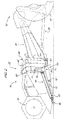
- FIG. 2 shows a side-view of a combine 10, illustrating an embodiment for a floating header configuration 50 for a draper-type header.
- the header 50 includes a frame 52 having a conventional configuration, the frame 52 supporting a reel assembly 54, a cutter-bar assembly 56, and a draper assembly 58.
- a floating suspension system 60 extending from the rear of the frame 52 primarily supports the header 50 from the feederhouse 20, while downward extending support member 62 serves to secondarily support the header 50 from the ground.
- this support member is a skid plate 62 located near the front of the frame 52, however the portion could also be a gage-wheel (not shown).
- the suspension system 60 includes a sub-frame 64 removably attaching to the feederhouse 20, one or more lower links 66, one or more upper links 68, one or more float cylinders 70, a float circuit 72, and a float valve 74.
- the illustrated embodiment employs two parallel lower links 66, each having a first end 67 pivotally attaching near the bottom of the sub-frame 64. Each lower link 66 extends forward and has a second end 67' pivotally attaching beneath the header frame 52.
- the illustrated embodiment uses one upper link 68, having a first end 69 pivotally attaching near the top of the sub-frame 64.
- the upper link 68 extends forward and has a second end 69' pivotally attaching high on the header frame 52.
- each float cylinder 70 has a first end 71 attaching to its corresponding lower link 66 near the lower link first end 67.
- Each float cylinder 70 extends upward and has a second end 71' attaching to the header frame 52.
- Each float cylinder 70 is a single acting hydraulic cylinder adapted to independently reciprocate over a limit range.
- Each float cylinder 70 connects to the float circuit 72, which in turn connects to the main hydraulic circuit 40 via the float valve 74.
- the float valve 74 is adapted to selectively add and subtract hydraulic fluid from the float circuit 72.
- the illustrated float valve 74 is an electronically controlled hydraulic valve commanded by the controller 44.
- the float valve 74 is optionally located either on the floating header 22 or on the combine 10.
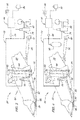
- Figures 3 and 4 show schematics illustrating first and second embodiments, 80, 82 respectively, for header float systems used with the floating header 50.
- the first embodiment 80 is a dynamic float system
- the second embodiment 82 is a resilient float system. Both header float systems serve to reduce the apparent weight of the header 50 when the working height is such that the header 50 remains in contact with the ground, illustrated in Figure 5A.
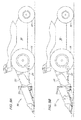
- the header 50 lightly skids across the ground as the combine 10 moves forward during a harvesting operation, enabling the header 50 to follow changing terrain automatically within the limits of the suspension system 60.
- the ground urges the header 50 up as slope inclines, illustrated in Figure 5B, and gravity urges the header 50 down as slope declines, illustrated in Figure 5C.
- the header 50 provides some role angle floatation relative to the combine 10 due to independent reciprocation of each float cylinder 70, illustrated in Figures 6A and 6B.
- a pressure sensor 84 in communication with the controller 44 connects to the float circuit 72 between the float cylinders 70 and the float valve 74.
- operator input devices in communication with the controller 44 allow the operator to control the function of the float system in both embodiments.
- Operator input devices include, but are not limited to, a float activation device 86 and a float setting device 88. Examples of float activation devices 86 include toggle switches or push buttons. Examples of float setting devices 88 include analog dial input devices or digital input devices. Not shown, an optional shut-off valve isolates the float cylinders 70 from the hydraulic circuit 40, allowing for service of the header 50.
- the second embodiment 82 further includes an accumulator 90 connecting to the float circuit 72 between the float cylinders 70 and float valve 74.
- the operator engages the float activation device 86 to operate the header 50 in a float mode, and may also manipulate the float setting device 88 for desired header float response.
- the controller 44 reads the float setting device 88, indicating a level of suspension support required of the float system 80, 82 by the operator, for example, as percent of header weight or desired pressure in the float circuit. The controller 44 then determines a target pressure in the float circuit adequate to provide the suspension support commanded.
- the controller 44 may reference data correlating pressure values in the float circuit 72 with suspension support values. This correlated pressure data will vary from header to header as a function of header weight and suspension configuration, and may generate from tables, formulas, or sensor readings.
- the controller 44 might read the correlated data from a storage device on the header 50. Data might also be stored in memory internal to the combine, with the controller 44 selecting the appropriate data after sensing the header type attached to the combine 10.
- the controller 44 may determine the target pressure for the float circuit 72 by reading the pressure sensor 84 in the float circuit 72 when the header 50 is at a height where the skid plates are not in contact with the ground. At such a height, the suspension supports the entire weight of the header, and the pressure in the float circuit indicates a baseline pressure whereby the float cylinders 70 entirely support the header 50. The controller 44 then determines the target pressure by multiplying the baseline pressure by a factor corresponding to the suspension support indicated from the float setting device 88.
- the controller 44 continuously compares the target pressure with pressure sensor 84 readings indicating pressure in the float circuit 72, commanding the float valve 74 to add or subtract hydraulic fluid from the float circuit 72 to maintain pressure sensor 84 readings equal to the target pressure. In this manner, the controller 44 continuously maintains target pressure in the float circuit 72 as the float cylinders 70 reciprocate over changing terrain, providing constant support of the header 50 by the float suspension 60 as the combine 10 travels through the field. To change header float response while operating in header float mode, the operator may further manipulate the float setting device 88 without disengaging the float system. The controller 44 continuously monitors the float setting device 88 for changes, determining and applying new target pressures accordingly. The header float system continues to function until the operator disengages the float activation device 86.
- the controller 44 only initially compares the target pressure with the pressure sensor 84 readings indicating float circuit 72 pressure, commanding the float valve 74 to add or subtract hydraulic fluid from the float circuit 72 until the reading from the pressure sensor 84 matches the target pressure.
- the float circuit 72 is sealed and the accumulator 90 acts to maintain target pressure in the float circuit 72 as the float cylinders 70 reciprocate over changing terrain.
- the operator may further manipulate the float setting device 88 without disengaging the float system.
- the controller 44 continuously monitors the float setting device 88 for changes, determining and applying new target pressures accordingly.
- the header float system continues to function until the operator disengages the float activation device 86.
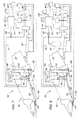
- Figures 7 and 8 show schematics illustrating first and second embodiments, 92, 94 respectively, for a terrain following system used with the floating header 50. Both systems serve to extend the terrain following capability of the floating header system 80, 82 by dynamically actuating the lift cylinders 24 in response to reciprocation of the float cylinders 70.
- the terrain following system 92, 94 causes the lift cylinders 24 to raise the header 50 upward such that the float cylinders 70 return to a nominal position, shown in Figure 9C.
- the terrain following system 92, 94 causes the lift cylinders 24 to lower the header 50 downward such that the float cylinders 70 again return to their nominal position, shown in Figure 9E.
- the first embodiment 92 is a terrain following system used with the dynamic header float system 80
- the second embodiment 94 is a terrain following system used with the resilient header float system 82.
- a position sensor 96 in communication with the controller 44 in the form of a potentiometer, indicates relative reciprocation of each cylinder.
- each position sensor 96 attaches to a corresponding lower link 66 and to the frame 52.
- operator input devices in communication with the controller 44 allow the operator to control the function of the terrain following system 92, 94.
- Operator input devices include, but are not limited to, a lift command device 98 and a system activation device 100. Examples of system activation devices 100 include toggle switches or push buttons. Examples of lift command devices 98 include levers or joystick controls.
- the operator manipulates the lift command device 98, causing the controller 44 to command the lift cylinders 24 to lower the header 50 until the header 50 contacts the ground.
- the operator then engages the system activation device 100 to operate in a terrain following mode.
- the controller 44 continuously reads both position sensors 96, calculates the average of the position sensor 96 readings, and then commands the lift valve 42 to add or subtract hydraulic fluid from the lift cylinders 24 until the average of the position sensor 96 readings indicate that the float cylinders 72 are at their nominal position.
- the controller 44 continuously adjusts header height over changing terrain, positioning the float header 50 for optimal function of the header float system 80, 82 as the combine 10 travels through the field.
- the terrain following system 92, 94 continues to function until the operator disengages the system activation device 100, or until the operator manipulates the lift command device 98 to raise or lower the header 50.
Landscapes
- Life Sciences & Earth Sciences (AREA)
- Environmental Sciences (AREA)
- Harvester Elements (AREA)
- Vehicle Body Suspensions (AREA)
- Transplanting Machines (AREA)
Abstract
a floating header (50) having a frame (52), a support member (62) supporting the frame (52) from the ground, and a suspension (60) variably supporting the frame (52) from the combine (10) having one or more float cylinders (70) moveably supporting the frame (52) from a sub-frame (64), the floating header (50) further having a float circuit (72), and a float valve (74);
a pressure sensor (84) connecting to the float circuit (72); and
a controller (44), that maintains pressure in the float circuit (72) at a target value by continuously reading pressure sensed by the pressure sensor (84) and commanding the float valve (74) to add and subtract hydraulic fluid in the float circuit (72) in response.
Description
- The present invention relates to floating platform and draper-type headers for agricultural combines. The present invention also relates to header float systems and header terrain following systems for agricultural combines.
- An agricultural combine is a large machine used to harvest a variety of crops from a field. During a harvesting operation, a header at the front of the combine cuts ripened crop from the field. A feederhouse supporting the header transfers the crop material into the combine. Threshing and separating assemblies within the combine remove grain from the crop material and transfer the clean grain to a grain tank for temporary holding. Crop material other than grain exits from the rear of the combine. An unloading auger transfers the clean grain from the grain tank to a truck or grain cart for transport, or to another receiving bin for holding.
- Platform headers and draper headers are header types commonly used when harvesting crops such as small grains, peas, lentils, and rice. During a harvesting operation with these header types, it is desirable to maintain a cutting height as low as possible to the ground in order to collect substantially the entire ripe crop from the field. To accomplish this, combines typically employ a header float system or a terrain following system to enable the header to follow the ground over changing terrain without gouging or digging into the soil.
- Manufacturers have developed a number of such systems over the years.
US 3 717 995 A ,US 3 623 304 A , andUS 4 724 661 A disclose examples of header float systems using resilient means to suspend the header, thereby reducing the apparent weight of the header, allowing it to lightly skid across the ground over changing terrain.US 3 597 907 A ,US 4 622 803 A andUS 5 471 823 A disclose examples of similar float systems, but using dynamic means to suspend the header.US 5 577 373 A ,US 6 041 583 A andUS 6 758 029 B disclose examples of terrain following systems using dynamic means to position the header, thereby sensing and changing the vertical position of the header to follow changing terrain. - The invention presents a floating header design implemented with a draper-type header. The header includes a frame having a conventional configuration, and a floating suspension system extending from the frame having a sub-frame removably attaching to the feederhouse. Float cylinders extending between the frame and sub-frame moveably support the header from the combine. The float cylinders connect to a float circuit, which in turn connects to a main hydraulic circuit on the combine by a float valve. The float valve is an electronically controlled hydraulic valve commanded by a controller.
- In a first embodiment of a header float system used with the floating header, the controller continuously maintains a target pressure in the float circuit as the float cylinders reciprocate over changing terrain. In header float mode, the system provides constant support of the header by the float suspension as the combine travels through the field. In a second embodiment of a header float system, the controller only initially charges and seals pressure in the float circuit to a target value, with an accumulator acting to maintain target pressure in the float circuit as the float cylinders reciprocate over changing terrain. In a terrain following system, the controller continuously adjusts header height over changing terrain by raising and lowering the feederhouse in response to movement of the floating header suspension. When operating in this mode, the controller maintains the position of the float header for optimal function of the header float system as the combine travels through the field.
- In the following, embodiments of the invention are described based upon the drawings, in which:
- Figure 1 is a side-view of a combine, showing a floating header having an integrated hydraulic float suspension.
- Figure 2 is a partial side-view of the combine, showing the floating header attached at the front of a feederhouse.
- Figure 3 is a schematic for a dynamic header float system used with the illustrated floating header.
- Figure 4 is a schematic for a resilient header float system used with the illustrated floating header.
- Figure 5A shows a side-view of the combine operating on level ground with an illustrated float system and the floating header.
- Figure 5B shows a side-view of the combine operating on inclining ground with an illustrated float system and the floating header.
- Figure 5C shows a side-view of the combine operating on declining ground with an illustrated float system and the floating header.
- Figure 6A shows a front-view of the combine operating on right-rolling ground with an illustrated float system and the floating header.
- Figure 6B shows a front-view of the combine operating on left-rolling ground with an illustrated float system and the floating header.
- Figure 7 is a schematic for a dynamic header terrain following system combined with the illustrated dynamic float system and floating header.
- Figure 8 is a schematic for a dynamic header terrain following system combined with the illustrated resilient float system and floating header.
- Figure 9A shows a side-view of the combine operating on level ground with the illustrated dynamic header terrain following system and floating header.
- Figure 9B shows the combine operating on inclining ground with the illustrated dynamic header terrain following system at a first instance.
- Figure 9C shows the combine operating on inclining ground with the illustrated dynamic header terrain following system at a second instance.
- Figure 9D shows the combine operating on declining ground with the illustrated dynamic header terrain following system at a first instance.
- Figure 9E shows the combine operating on declining ground with the illustrated dynamic header terrain following system at a second instance.
- Figure 1 illustrates a self-
propelled combine 10 commonly used in a grain farming to harvest a variety of crops from a field. An onboard engine powers the combine 10, while groundengaging wheels 14 support and propel the machine. An operator controls thecombine 10 from an operator's station located in acab 16 at the front of the machine. Anelectronic controller 44, which receives commands from operator input devices and sensors, commands various function of thecombine 10. - A
feederhouse 20 pivotally attaches at the front of thecombine 10, supporting aheader 22 removably attached to the front of thefeeder house 20. A pair oflift cylinders 24 support and articulate thefeederhouse 20 from thecombine 10, enabling the raising and lowering of theheader 22 relative to the ground. Thelift cylinders 24 are single or double acting hydraulic cylinders connected to a mainhydraulic circuit 40 by alift valve 42. Thelift valve 42 is an electronically controlled hydraulic valve commanded by thecontroller 44. - During a harvesting operation, the
combine 10 moves forward through the field with theheader 22 lowered to a working height. Theheader 22 cuts and transfers crop material to thefeederhouse 20, which in turn transfers the crop material into thecombine 10. Once inside the combine, threshing and separatingassemblies 26 remove grain from the crop material and transfer it to agrain tank 28 for temporary holding. Crop material other than grain exits from the rear of thecombine 10. Anunloading auger 30 transfers the grain from thegrain tank 28 to a truck or grain cart for transport, or to another receiving bin for holding. - Figure 2 shows a side-view of a
combine 10, illustrating an embodiment for afloating header configuration 50 for a draper-type header. Theheader 50 includes aframe 52 having a conventional configuration, theframe 52 supporting areel assembly 54, a cutter-bar assembly 56, and adraper assembly 58. Afloating suspension system 60 extending from the rear of theframe 52 primarily supports theheader 50 from thefeederhouse 20, while downward extendingsupport member 62 serves to secondarily support theheader 50 from the ground. In the illustrated embodiment, this support member is askid plate 62 located near the front of theframe 52, however the portion could also be a gage-wheel (not shown). - The
suspension system 60 includes asub-frame 64 removably attaching to thefeederhouse 20, one or morelower links 66, one or moreupper links 68, one ormore float cylinders 70, afloat circuit 72, and afloat valve 74. The illustrated embodiment employs two parallellower links 66, each having afirst end 67 pivotally attaching near the bottom of thesub-frame 64. Eachlower link 66 extends forward and has a second end 67' pivotally attaching beneath theheader frame 52. The illustrated embodiment uses oneupper link 68, having afirst end 69 pivotally attaching near the top of thesub-frame 64. Theupper link 68 extends forward and has a second end 69' pivotally attaching high on theheader frame 52. - In the illustrated embodiment, two
float cylinders 70, one corresponding to eachlower link 66, support theframe 52 from thesub-frame 64. Eachfloat cylinder 70 has afirst end 71 attaching to its correspondinglower link 66 near the lower linkfirst end 67. Eachfloat cylinder 70 extends upward and has a second end 71' attaching to theheader frame 52. Eachfloat cylinder 70 is a single acting hydraulic cylinder adapted to independently reciprocate over a limit range. Eachfloat cylinder 70 connects to thefloat circuit 72, which in turn connects to the mainhydraulic circuit 40 via thefloat valve 74. Thefloat valve 74 is adapted to selectively add and subtract hydraulic fluid from thefloat circuit 72. The illustratedfloat valve 74 is an electronically controlled hydraulic valve commanded by thecontroller 44. Thefloat valve 74 is optionally located either on the floatingheader 22 or on thecombine 10. - Figures 3 and 4 show schematics illustrating first and second embodiments, 80, 82 respectively, for header float systems used with the floating
header 50. Thefirst embodiment 80 is a dynamic float system, while thesecond embodiment 82 is a resilient float system. Both header float systems serve to reduce the apparent weight of theheader 50 when the working height is such that theheader 50 remains in contact with the ground, illustrated in Figure 5A. - With the apparent weight reduced, the
header 50 lightly skids across the ground as thecombine 10 moves forward during a harvesting operation, enabling theheader 50 to follow changing terrain automatically within the limits of thesuspension system 60. As theheader 50 skids forward, the ground urges theheader 50 up as slope inclines, illustrated in Figure 5B, and gravity urges theheader 50 down as slope declines, illustrated in Figure 5C. Additionally, theheader 50 provides some role angle floatation relative to thecombine 10 due to independent reciprocation of eachfloat cylinder 70, illustrated in Figures 6A and 6B. - In the
first embodiment 80, apressure sensor 84 in communication with thecontroller 44 connects to thefloat circuit 72 between thefloat cylinders 70 and thefloat valve 74. Within thecab 16, operator input devices in communication with thecontroller 44 allow the operator to control the function of the float system in both embodiments. Operator input devices include, but are not limited to, afloat activation device 86 and afloat setting device 88. Examples offloat activation devices 86 include toggle switches or push buttons. Examples offloat setting devices 88 include analog dial input devices or digital input devices. Not shown, an optional shut-off valve isolates thefloat cylinders 70 from thehydraulic circuit 40, allowing for service of theheader 50. Having all of the elements of thefirst embodiment 80, thesecond embodiment 82 further includes anaccumulator 90 connecting to thefloat circuit 72 between thefloat cylinders 70 andfloat valve 74. - During a harvesting operation with either
embodiment float activation device 86 to operate theheader 50 in a float mode, and may also manipulate thefloat setting device 88 for desired header float response. Once engaged in the header float mode, thecontroller 44 reads thefloat setting device 88, indicating a level of suspension support required of thefloat system controller 44 then determines a target pressure in the float circuit adequate to provide the suspension support commanded. - To determine the target pressure for the
float circuit 72, thecontroller 44 may reference data correlating pressure values in thefloat circuit 72 with suspension support values. This correlated pressure data will vary from header to header as a function of header weight and suspension configuration, and may generate from tables, formulas, or sensor readings. Thecontroller 44 might read the correlated data from a storage device on theheader 50. Data might also be stored in memory internal to the combine, with thecontroller 44 selecting the appropriate data after sensing the header type attached to thecombine 10. - Alternatively, the
controller 44 may determine the target pressure for thefloat circuit 72 by reading thepressure sensor 84 in thefloat circuit 72 when theheader 50 is at a height where the skid plates are not in contact with the ground. At such a height, the suspension supports the entire weight of the header, and the pressure in the float circuit indicates a baseline pressure whereby thefloat cylinders 70 entirely support theheader 50. Thecontroller 44 then determines the target pressure by multiplying the baseline pressure by a factor corresponding to the suspension support indicated from thefloat setting device 88. - In the
first embodiment 80, thecontroller 44 continuously compares the target pressure withpressure sensor 84 readings indicating pressure in thefloat circuit 72, commanding thefloat valve 74 to add or subtract hydraulic fluid from thefloat circuit 72 to maintainpressure sensor 84 readings equal to the target pressure. In this manner, thecontroller 44 continuously maintains target pressure in thefloat circuit 72 as thefloat cylinders 70 reciprocate over changing terrain, providing constant support of theheader 50 by thefloat suspension 60 as thecombine 10 travels through the field. To change header float response while operating in header float mode, the operator may further manipulate thefloat setting device 88 without disengaging the float system. Thecontroller 44 continuously monitors thefloat setting device 88 for changes, determining and applying new target pressures accordingly. The header float system continues to function until the operator disengages thefloat activation device 86. - In the
second embodiment 82, thecontroller 44 only initially compares the target pressure with thepressure sensor 84 readings indicatingfloat circuit 72 pressure, commanding thefloat valve 74 to add or subtract hydraulic fluid from thefloat circuit 72 until the reading from thepressure sensor 84 matches the target pressure. Once charged to the target pressure, thefloat circuit 72 is sealed and theaccumulator 90 acts to maintain target pressure in thefloat circuit 72 as thefloat cylinders 70 reciprocate over changing terrain. To change header float response while operating in header float mode, the operator may further manipulate thefloat setting device 88 without disengaging the float system. Thecontroller 44 continuously monitors thefloat setting device 88 for changes, determining and applying new target pressures accordingly. The header float system continues to function until the operator disengages thefloat activation device 86. - Figures 7 and 8 show schematics illustrating first and second embodiments, 92, 94 respectively, for a terrain following system used with the floating
header 50. Both systems serve to extend the terrain following capability of the floatingheader system lift cylinders 24 in response to reciprocation of thefloat cylinders 70. As the ground urges theheader 50 up on inclines, shown in Figure 9B, theterrain following system lift cylinders 24 to raise theheader 50 upward such that thefloat cylinders 70 return to a nominal position, shown in Figure 9C. As gravity urges theheader 50 down on declines, shown in Figure 9D, theterrain following system lift cylinders 24 to lower theheader 50 downward such that thefloat cylinders 70 again return to their nominal position, shown in Figure 9E. - The
first embodiment 92 is a terrain following system used with the dynamicheader float system 80, while thesecond embodiment 94 is a terrain following system used with the resilientheader float system 82. In both embodiments, aposition sensor 96 in communication with thecontroller 44, in the form of a potentiometer, indicates relative reciprocation of each cylinder. In the illustrated embodiments, eachposition sensor 96 attaches to a correspondinglower link 66 and to theframe 52. Within thecab 16, operator input devices in communication with thecontroller 44 allow the operator to control the function of theterrain following system lift command device 98 and asystem activation device 100. Examples ofsystem activation devices 100 include toggle switches or push buttons. Examples oflift command devices 98 include levers or joystick controls. - During a harvesting operation with either
embodiment lift command device 98, causing thecontroller 44 to command thelift cylinders 24 to lower theheader 50 until theheader 50 contacts the ground. The operator then engages thesystem activation device 100 to operate in a terrain following mode. Once engaged, thecontroller 44 continuously reads bothposition sensors 96, calculates the average of theposition sensor 96 readings, and then commands thelift valve 42 to add or subtract hydraulic fluid from thelift cylinders 24 until the average of theposition sensor 96 readings indicate that thefloat cylinders 72 are at their nominal position. In this manner, thecontroller 44 continuously adjusts header height over changing terrain, positioning thefloat header 50 for optimal function of theheader float system combine 10 travels through the field. Theterrain following system system activation device 100, or until the operator manipulates thelift command device 98 to raise or lower theheader 50.
Claims (8)
- A floating header (50) comprising:a frame (52),a support member (62) supporting the frame (52) from the ground,a suspension (60) having a sub-frame (64) that can be removably attached to a feederhouse (20) at the front of a combine (10), a plurality of links (66) movably attaching the frame (52) and the sub-frame (66), and one or more float cylinder (70) moveably supporting the frame (52) from the sub-frame (64),the floating header (50) further having a float circuit (72) connecting to each float cylinder (70), and a float valve (74) operable to connect the float circuit (72) to a main hydraulic circuit (40) of the combine (10), the float valve (74) adapted to controllably add and subtract hydraulic fluid in the float circuit (72);a pressure sensor (84) connecting to the float circuit (72), the pressure sensor (84) adapted to sense hydraulic pressure in the float circuit (72); anda controller (44), that when engaged in a header float mode, operable to maintain pressure in the float circuit (72) at a target value by continuously reading pressure sensed by the pressure sensor (84) and commanding the float valve (74) to add and subtract hydraulic fluid in the float circuit (72) in response.
- A header (50) according to claim 1 wherein the target value for float circuit pressure is sufficient to cause the float cylinders (70) to provide a desired suspension support from the combine (10) when the header (50) is at a working height with the support member (62) contacting the ground.
- A header (50) according to claim 1 or 2 further comprising a float setting device (88) in communication with the controller, the float setting device (88) adapted to receive operator commands defining the desired suspension support.
- A header (50) according to one of claims 1 to 3 further comprising a float activation device (86) in communication with the controller (44), the float activation device (86) adapted to receive operator commands for engagement and disengagement of the header float mode.
- A header (50) according to one of claims 1 to 4 wherein the controller (44) is operable to determine the target value for float circuit pressure by comparing the desired suspension support with data correlating float circuit pressure values to suspension support values.
- A header (50) according to one of claims 1 to 5 wherein the controller (44) is operable to determine the target value for float circuit pressure by reading pressure sensed by the pressure sensor (84) when the header (50) is at a height without the support member (62) contacting the ground, and multiplying the reading by a factor corresponding to the desired suspension support.
- A header (50) according to one of the preceding claims, further comprising an accumulator (90) connecting to the float circuit (72), the accumulator (90) adapted to maintain constant hydraulic pressure in the float circuit (72).
- An agricultural combine (10) having a main hydraulic circuit (40), a dynamic header float system (80, 82) and a header (50) according to one of the preceding claims.
Applications Claiming Priority (1)
| Application Number | Priority Date | Filing Date | Title |
|---|---|---|---|
| US11/125,419 US7222475B2 (en) | 2005-05-10 | 2005-05-10 | Header hydraulic float system |
Publications (1)
| Publication Number | Publication Date |
|---|---|
| EP1721507A1 true EP1721507A1 (en) | 2006-11-15 |
Family
ID=36716995
Family Applications (1)
| Application Number | Title | Priority Date | Filing Date |
|---|---|---|---|
| EP06113448A Withdrawn EP1721507A1 (en) | 2005-05-10 | 2006-05-03 | Header hydraulic float system |
Country Status (4)
| Country | Link |
|---|---|
| US (1) | US7222475B2 (en) |
| EP (1) | EP1721507A1 (en) |
| AU (1) | AU2006201954B2 (en) |
| CA (1) | CA2540780C (en) |
Cited By (7)
| Publication number | Priority date | Publication date | Assignee | Title |
|---|---|---|---|---|
| WO2009049962A1 (en) * | 2007-10-11 | 2009-04-23 | Deere & Company | Hydraulic lifting device |
| WO2013101869A3 (en) * | 2011-12-28 | 2013-09-26 | Agco Corporation | Tilt accumulator for corn header |
| EP2705742A1 (en) * | 2012-09-10 | 2014-03-12 | SARL Belair | Control means between a cutting device and a conveyor mounted together on a vehicle |
| WO2014178868A1 (en) * | 2013-05-02 | 2014-11-06 | Agco Corporation | Variable precharge accumulator for agricultural header |
| US9532497B2 (en) | 2012-05-02 | 2017-01-03 | Agco Corporation | Variable precharge accumulator for agricultural header |
| WO2019136260A1 (en) * | 2018-01-04 | 2019-07-11 | Cnh Industrial America Llc | Draper header for harvester and methods of using the same |
| US20220394928A1 (en) * | 2021-06-15 | 2022-12-15 | Cnh Industrial America Llc | System and method for adjusting the position of a harvesting implement of an agricultural harvester |
Families Citing this family (60)
| Publication number | Priority date | Publication date | Assignee | Title |
|---|---|---|---|---|
| US7703266B2 (en) * | 2004-04-12 | 2010-04-27 | Cnh America Llc | Method for managing the electrical control system of a windrower header flotation and lift system |
| US7552577B2 (en) * | 2005-09-29 | 2009-06-30 | Cnh America Llc | Header flotation calibration system |
| US20080276590A1 (en) * | 2006-02-10 | 2008-11-13 | Agco Corporation | Flexible draper and cutter bar with tilt arm for cutterbar drive |
| US20080271426A1 (en) * | 2006-02-10 | 2008-11-06 | Agco Corporation | Draper belt with crop-retaining rib |
| US20070193243A1 (en) | 2006-02-10 | 2007-08-23 | Schmidt James R | Combine Harvester Draper Header Having Flexible Cutterbar |
| US7467506B2 (en) * | 2006-03-02 | 2008-12-23 | Deere & Company | Lockout for float arms in a cutting platform of an agricultural harvesting machine |
| US7478521B2 (en) * | 2006-03-02 | 2009-01-20 | Deere & Company | Flexible cutting platform to follow ground contour in an agricultural harvesting machine |
| US20090266044A1 (en) | 2008-04-25 | 2009-10-29 | Coers Bruce A | Integrated draper belt support and skid shoe in an agricultural harvesting machine |
| US20090277148A1 (en) * | 2008-05-09 | 2009-11-12 | Agco Corporation | Flexible draper and cutter bar having shiftable crop divider with deflector |
| EP2312927B1 (en) * | 2008-05-09 | 2011-12-28 | Agco Corporation | Center crop deflector for draper header |
| US7921627B2 (en) | 2008-05-09 | 2011-04-12 | Agco Corporation | Interlocking belt guards for a draper header |
| US20090277144A1 (en) * | 2008-05-09 | 2009-11-12 | Agco Corporation | Spring flotation for center deck of draper header |
| US20090277145A1 (en) | 2008-05-09 | 2009-11-12 | Agco Corporation | Header height control system with multiple potentiometer input |
| EP2315514B1 (en) * | 2008-05-09 | 2012-04-25 | Agco Corporation | Adjustable cutterbar travel range for a flexible cutterbar header |
| US7886511B2 (en) | 2008-05-09 | 2011-02-15 | Agco Corporation | Draper head with flexible cutterbar having rigid center section |
| US7707811B1 (en) * | 2009-04-15 | 2010-05-04 | Cnh America Llc | Header flotation and lift system with dual mode operation for a plant cutting machine |
| US7930871B1 (en) * | 2010-03-29 | 2011-04-26 | Cnh America Llc | Cutterbar support for a crop harvesting header |
| US8051633B2 (en) * | 2010-03-29 | 2011-11-08 | Cnh America Llc | Cutterbar adjustment support for a crop harvesting header |
| US7950212B1 (en) * | 2010-03-29 | 2011-05-31 | Cnh America Llc | Cutterbar support for a crop harvesting header |
| US8205421B2 (en) | 2010-06-16 | 2012-06-26 | Agco Corporation | Belt guard crop dam for flexible draper header |
| US7958711B1 (en) | 2010-06-16 | 2011-06-14 | Agco Corporation | Crop deflector for ends of draper belt of flexible draper header |
| BE1020181A3 (en) * | 2011-07-20 | 2013-06-04 | Cnh Belgium Nv | LIFTING SYSTEM FOR HARVESTING MACHINE. |
| US8479483B1 (en) | 2011-12-27 | 2013-07-09 | Agco Corporation | Flexible draper head providing reduced crop residue accumulation |
| WO2013101863A1 (en) * | 2011-12-28 | 2013-07-04 | Agco Corporation | Fore and aft tilt for corn header |
| US8695315B2 (en) * | 2012-08-09 | 2014-04-15 | Deere & Company | Draper header with pivoting side draper conveyors |
| US8601779B1 (en) * | 2012-09-04 | 2013-12-10 | Cnh America Llc | System for cutterbar support having torsion device with elastic material and load limiting apparatus |
| DE102012223769A1 (en) * | 2012-12-19 | 2014-06-26 | Deere & Company | Inclined conveyor assembly with improved swing axle |
| DE102012223770A1 (en) * | 2012-12-19 | 2014-06-26 | Deere & Company | Inclined conveyor assembly with flexible bottom |
| BE1022622B1 (en) * | 2015-03-27 | 2016-06-17 | Cnh Industrial Belgium Nv | Mower mounting frame |
| GB201607568D0 (en) * | 2016-04-29 | 2016-06-15 | Agco Do Brazil Com E Ind Ltda | Harvester header pitch adjustment apparatus |
| US9968033B2 (en) * | 2016-06-21 | 2018-05-15 | Macdon Industries Ltd. | Crop machine with an electronically controlled hydraulic cylinder flotation system |
| US10278330B2 (en) * | 2016-10-11 | 2019-05-07 | Deere & Company | Combine feeder house gauge wheels |
| CN106797750B (en) * | 2017-02-04 | 2022-08-19 | 华中农业大学 | Header of combine harvester |
| US10405474B2 (en) * | 2017-04-30 | 2019-09-10 | Deere & Company | Multilink connection between harvesting head adapter frame and mainframe |
| BR102017010859B1 (en) * | 2017-05-24 | 2022-12-13 | Cnh Industrial Brasil Ltda | STRUCTURAL SET FOR ASSEMBLY OF A PLATFORM |
| BR102017010857A2 (en) * | 2017-05-24 | 2018-12-18 | CNH Industrial Brasil Ltda. | structural assembly for mounting a platform and harvester |
| US10405480B2 (en) | 2017-06-28 | 2019-09-10 | Cnh Industrial America Llc | Closed-loop dual-pressure position control of an implement stabilizer wheel |
| US10412877B2 (en) | 2017-06-28 | 2019-09-17 | Cnh Industrial Canada, Ltd. | Cylinder pressure based position control of an implement stabilizer wheel |
| US10517215B2 (en) * | 2017-10-12 | 2019-12-31 | Deere & Company | Roll center for attachment frame control arms |
| US10569612B2 (en) | 2017-12-11 | 2020-02-25 | Cnh Industrial America Llc | Suspension control system providing tire height corrections for an agricultural machine |
| US10730359B2 (en) | 2017-12-11 | 2020-08-04 | Cnh Industrial America Llc | Suspension control system providing suspension height corrections for an agricultural machine |
| US10436622B2 (en) | 2017-12-11 | 2019-10-08 | Cnh Industrial America Llc | Suspension control system providing closed loop control of hydraulic fluid volumes for an agricultural machine |
| US10183542B1 (en) | 2017-12-11 | 2019-01-22 | Cnh Industrial America Llc | Suspension control system providing orientation control for an agricultural machine |
| DE102018107804A1 (en) * | 2018-04-03 | 2019-10-10 | Claas Selbstfahrende Erntemaschinen Gmbh | Height control system for a header |
| US10820510B2 (en) * | 2018-06-15 | 2020-11-03 | Deere & Company | Cutterbar angle change with four bar linkage |
| US10820466B2 (en) * | 2018-07-05 | 2020-11-03 | Deere & Company | Orificed check valve in wing circuit |
| US10820511B2 (en) * | 2018-07-05 | 2020-11-03 | Deere & Company | Wing locking with hydraulic blocker valve |
| US11032970B2 (en) | 2018-10-30 | 2021-06-15 | Deere & Company | Varying a hydraulic cylinder mechanical advantage to obtain smoother float pressure |
| US12150409B2 (en) * | 2018-11-16 | 2024-11-26 | Cnh Industrial America Llc | Airbag system for a harvester header |
| AR118624A1 (en) | 2019-04-10 | 2021-10-20 | Cnh Ind America Llc | OVERLOAD DETECTION SYSTEM FOR A HARVEST HEAD |
| US11516964B2 (en) * | 2019-04-30 | 2022-12-06 | Deere & Company | Position controlled gauge wheels on a harvesting machine header that move with a feeder house move command |
| US11064654B2 (en) * | 2019-05-01 | 2021-07-20 | Deere & Company | Float adjustment |
| AU2020354792A1 (en) * | 2019-09-25 | 2022-04-07 | Tigercat Industries Inc. | System and method for control of silvicultural equipment |
| US11375654B2 (en) * | 2019-10-08 | 2022-07-05 | Deere & Company | Method and apparatus for adjusting a harvesting header float system based on machine pitch or terrain and system thereof |
| US11497164B2 (en) | 2019-10-22 | 2022-11-15 | Cnh Industrial America Llc | Header suspension for pivoting header of combine harvester |
| US11375664B2 (en) * | 2019-11-16 | 2022-07-05 | Cnh Industrial America Llc | Agricultural header with linearly displaceable flex arms |
| US11399464B2 (en) * | 2020-10-21 | 2022-08-02 | Deere & Company | Windrower header floatation system having assisted downforce control |
| CN115633575A (en) * | 2022-10-09 | 2023-01-24 | 潍柴雷沃智慧农业科技股份有限公司 | Harvester header control method, system, device, equipment, medium and harvester |
| US12317773B2 (en) | 2023-02-07 | 2025-06-03 | Deere & Company | Self-propelled agricultural harvester machine and header assembly control system |
| US20250040484A1 (en) * | 2023-07-31 | 2025-02-06 | Agco Corporation | Method of Ground Load Sensing with Isolated Harvester Rotary Cutterbar |
Citations (12)
| Publication number | Priority date | Publication date | Assignee | Title |
|---|---|---|---|---|
| US3597907A (en) | 1965-02-15 | 1971-08-10 | Love Co J E | Header elevational control system for crop-harvesting machine |
| US3623304A (en) | 1970-03-30 | 1971-11-30 | Int Harvester Co | Hydraulic system for supporting a harvester platform |
| US3717995A (en) | 1971-10-12 | 1973-02-27 | Hesston Corp | Hydraulic flotation for implement header |
| US4409778A (en) * | 1980-01-10 | 1983-10-18 | Massey-Ferguson Services N.V. | Crop collecting apparatus |
| US4622803A (en) | 1984-06-28 | 1986-11-18 | J. I. Case Company | Header flotation |
| EP0208794A1 (en) * | 1985-07-11 | 1987-01-21 | De Rotterdamsche Droogdok Maatschappij B.V. | Cutting header for a harvesting machine |
| US4724661A (en) | 1986-09-04 | 1988-02-16 | New Holland Inc. | Two piece crop harvesting header and flotation mechanism therefor |
| US5471823A (en) | 1994-06-24 | 1995-12-05 | Case Corporation | Electronic combine head float control system |
| US5473870A (en) * | 1994-06-24 | 1995-12-12 | Case Corporation | Header control for returning to height or float control |
| US5577373A (en) | 1994-06-24 | 1996-11-26 | Case Corporation | Agricultural vehicle including a system for automatically moving an implement and improved ground height sensing to a predetermined operating position |
| US5906089A (en) * | 1997-07-17 | 1999-05-25 | Hay & Forage Industries | Slave cylinder stabilizer for harvester header |
| US6041583A (en) | 1998-11-16 | 2000-03-28 | Deere & Company | Height sensing system for a harvester head |
Family Cites Families (19)
| Publication number | Priority date | Publication date | Assignee | Title |
|---|---|---|---|---|
| US3959957A (en) | 1975-01-24 | 1976-06-01 | Sperry Rand Corporation | Crop harvesting machine header suspension system |
| US4193250A (en) * | 1978-11-29 | 1980-03-18 | Paul Revere Corporation | Height control for multi-row crop harvester |
| EP0018095B1 (en) | 1979-03-28 | 1984-07-04 | Ransomes Sims & Jefferies, Public Limited Company | Turf maintenance machine |
| US4437295A (en) | 1981-04-08 | 1984-03-20 | International Harvester Co. | Automatic header height control |
| US4776153A (en) | 1986-02-27 | 1988-10-11 | Deere & Company | Automatic height control for a laterally pivoted harvester header |
| DE3673519D1 (en) | 1986-05-02 | 1990-09-20 | Ford New Holland Inc | MACHINE TABLE VIBRATION DEVICE FOR AGRICULTURAL MACHINE. |
| US5005343A (en) | 1988-06-22 | 1991-04-09 | Macdon Industries Ltd. | Header for a combine harvesting machine |
| US5359836A (en) | 1993-02-01 | 1994-11-01 | Control Concepts, Inc. | Agricultural harvester with closed loop header control |
| CA2110775C (en) | 1993-12-06 | 1999-03-02 | Gregory J. Honey | A feeder adapter for mounting a combine header to a feeder housing of a combine |
| CA2139443C (en) | 1995-01-03 | 2002-11-12 | Gregory J. Honey | Linkage device for mounting swather header |
| GB9519565D0 (en) | 1995-09-26 | 1995-11-29 | Ford New Holland Nv | Apparatus for controlling a position-adjustable implement |
| US5661964A (en) * | 1995-10-11 | 1997-09-02 | Pixall Limited Partnership | Fresh market sweet corn harvester |
| US5633452A (en) | 1996-03-29 | 1997-05-27 | Deere & Company | Low pressure warning for hydraulic system of platform float suspension |
| US5799483A (en) | 1996-08-29 | 1998-09-01 | Voss; Douglas A. | Combine harvester header lateral levelling |
| US5964077A (en) | 1997-07-17 | 1999-10-12 | Hay & Forage Industries | Dual accumulator hydraulic flotation system for crop harvester |
| CA2257049A1 (en) | 1997-12-31 | 1999-06-30 | Richard Gramm | Combine header height control |
| US5983615A (en) | 1998-11-03 | 1999-11-16 | Deere & Company | Windrower platform side-to-side float balance adjustment |
| CA2387898C (en) | 2001-06-18 | 2005-01-11 | Macdon Industries Ltd. | Multi-section header with flexible crop cutting knife |
| CA2369862C (en) | 2002-01-31 | 2009-10-27 | Norbert Beaujot | Header height control apparatus |
-
2005
- 2005-05-10 US US11/125,419 patent/US7222475B2/en not_active Expired - Lifetime
-
2006
- 2006-03-22 CA CA002540780A patent/CA2540780C/en not_active Expired - Fee Related
- 2006-05-03 EP EP06113448A patent/EP1721507A1/en not_active Withdrawn
- 2006-05-10 AU AU2006201954A patent/AU2006201954B2/en not_active Ceased
Patent Citations (12)
| Publication number | Priority date | Publication date | Assignee | Title |
|---|---|---|---|---|
| US3597907A (en) | 1965-02-15 | 1971-08-10 | Love Co J E | Header elevational control system for crop-harvesting machine |
| US3623304A (en) | 1970-03-30 | 1971-11-30 | Int Harvester Co | Hydraulic system for supporting a harvester platform |
| US3717995A (en) | 1971-10-12 | 1973-02-27 | Hesston Corp | Hydraulic flotation for implement header |
| US4409778A (en) * | 1980-01-10 | 1983-10-18 | Massey-Ferguson Services N.V. | Crop collecting apparatus |
| US4622803A (en) | 1984-06-28 | 1986-11-18 | J. I. Case Company | Header flotation |
| EP0208794A1 (en) * | 1985-07-11 | 1987-01-21 | De Rotterdamsche Droogdok Maatschappij B.V. | Cutting header for a harvesting machine |
| US4724661A (en) | 1986-09-04 | 1988-02-16 | New Holland Inc. | Two piece crop harvesting header and flotation mechanism therefor |
| US5471823A (en) | 1994-06-24 | 1995-12-05 | Case Corporation | Electronic combine head float control system |
| US5473870A (en) * | 1994-06-24 | 1995-12-12 | Case Corporation | Header control for returning to height or float control |
| US5577373A (en) | 1994-06-24 | 1996-11-26 | Case Corporation | Agricultural vehicle including a system for automatically moving an implement and improved ground height sensing to a predetermined operating position |
| US5906089A (en) * | 1997-07-17 | 1999-05-25 | Hay & Forage Industries | Slave cylinder stabilizer for harvester header |
| US6041583A (en) | 1998-11-16 | 2000-03-28 | Deere & Company | Height sensing system for a harvester head |
Cited By (9)
| Publication number | Priority date | Publication date | Assignee | Title |
|---|---|---|---|---|
| WO2009049962A1 (en) * | 2007-10-11 | 2009-04-23 | Deere & Company | Hydraulic lifting device |
| WO2013101869A3 (en) * | 2011-12-28 | 2013-09-26 | Agco Corporation | Tilt accumulator for corn header |
| US9532497B2 (en) | 2012-05-02 | 2017-01-03 | Agco Corporation | Variable precharge accumulator for agricultural header |
| EP2705742A1 (en) * | 2012-09-10 | 2014-03-12 | SARL Belair | Control means between a cutting device and a conveyor mounted together on a vehicle |
| WO2014178868A1 (en) * | 2013-05-02 | 2014-11-06 | Agco Corporation | Variable precharge accumulator for agricultural header |
| WO2019136260A1 (en) * | 2018-01-04 | 2019-07-11 | Cnh Industrial America Llc | Draper header for harvester and methods of using the same |
| US10827677B2 (en) | 2018-01-04 | 2020-11-10 | CNH Industrial America, LLC | Draper header for harvester providing floatation to gauge wheels |
| US20220394928A1 (en) * | 2021-06-15 | 2022-12-15 | Cnh Industrial America Llc | System and method for adjusting the position of a harvesting implement of an agricultural harvester |
| US12520762B2 (en) * | 2021-06-15 | 2026-01-13 | Cnh Industrial America Llc | System and method for adjusting the position of a harvesting implement of an agricultural harvester |
Also Published As
| Publication number | Publication date |
|---|---|
| CA2540780C (en) | 2009-06-09 |
| CA2540780A1 (en) | 2006-11-10 |
| AU2006201954B2 (en) | 2012-02-23 |
| US20060254232A1 (en) | 2006-11-16 |
| AU2006201954A1 (en) | 2006-11-30 |
| US7222475B2 (en) | 2007-05-29 |
Similar Documents
| Publication | Publication Date | Title |
|---|---|---|
| CA2540780C (en) | Header hydraulic float system | |
| EP1721508B1 (en) | Header hydraulic float suspension | |
| CA2540776C (en) | Header terrain following system | |
| US7430846B2 (en) | Floating header with integrated float system for use with an agricultural windrower or combine | |
| AU2008200792B2 (en) | Floating header with integrated float system for use with an agricultural windrower or combine | |
| AU2009210362B2 (en) | Header float system for use with an agricultural windrower or combine | |
| EP3675620B1 (en) | Method and system for controlling the height of an agricultural implement relative to the ground | |
| US7520115B2 (en) | Header float arm load compensation | |
| CN112616445B (en) | Method and system for adjusting header floating system based on machine pitching or terrain | |
| AU2011218639A1 (en) | Draper platform suspension | |
| AU2012241157A1 (en) | Header height control with tire flex compensation | |
| CA3079836A1 (en) | Float adjustment | |
| US12538865B2 (en) | Calibration of harvesting head having a ground force sensing system | |
| JP2007116914A (en) | Combine harvesting method and combine used for this harvesting method |
Legal Events
| Date | Code | Title | Description |
|---|---|---|---|
| PUAI | Public reference made under article 153(3) epc to a published international application that has entered the european phase |
Free format text: ORIGINAL CODE: 0009012 |
|
| AK | Designated contracting states |
Kind code of ref document: A1 Designated state(s): AT BE BG CH CY CZ DE DK EE ES FI FR GB GR HU IE IS IT LI LT LU LV MC NL PL PT RO SE SI SK TR |
|
| AX | Request for extension of the european patent |
Extension state: AL BA HR MK YU |
|
| 17P | Request for examination filed |
Effective date: 20070515 |
|
| AKX | Designation fees paid |
Designated state(s): BE DE FR GB IT |
|
| 17Q | First examination report despatched |
Effective date: 20070620 |
|
| STAA | Information on the status of an ep patent application or granted ep patent |
Free format text: STATUS: THE APPLICATION IS DEEMED TO BE WITHDRAWN |
|
| 18D | Application deemed to be withdrawn |
Effective date: 20170516 |