EP1721491B1 - Straight ribbon heater - Google Patents
Straight ribbon heater Download PDFInfo
- Publication number
- EP1721491B1 EP1721491B1 EP05723008A EP05723008A EP1721491B1 EP 1721491 B1 EP1721491 B1 EP 1721491B1 EP 05723008 A EP05723008 A EP 05723008A EP 05723008 A EP05723008 A EP 05723008A EP 1721491 B1 EP1721491 B1 EP 1721491B1
- Authority
- EP
- European Patent Office
- Prior art keywords
- layer
- heater
- base layer
- cover layer
- base
- Prior art date
- Legal status (The legal status is an assumption and is not a legal conclusion. Google has not performed a legal analysis and makes no representation as to the accuracy of the status listed.)
- Expired - Lifetime
Links
- 229920001296 polysiloxane Polymers 0.000 claims abstract description 34
- 238000010438 heat treatment Methods 0.000 claims abstract description 14
- 239000000835 fiber Substances 0.000 claims description 16
- 238000000034 method Methods 0.000 claims description 10
- 229920000106 Liquid crystal polymer Polymers 0.000 claims description 8
- 239000004977 Liquid-crystal polymers (LCPs) Substances 0.000 claims description 8
- 238000001723 curing Methods 0.000 claims description 8
- 229920001230 polyarylate Polymers 0.000 claims description 8
- 239000011152 fibreglass Substances 0.000 claims description 6
- 150000002978 peroxides Chemical class 0.000 claims description 6
- 238000004073 vulcanization Methods 0.000 claims description 3
- 239000003733 fiber-reinforced composite Substances 0.000 claims 6
- 238000005299 abrasion Methods 0.000 abstract description 11
- 239000012530 fluid Substances 0.000 abstract description 7
- 239000010410 layer Substances 0.000 description 99
- 238000012360 testing method Methods 0.000 description 16
- 239000004020 conductor Substances 0.000 description 7
- 230000007257 malfunction Effects 0.000 description 5
- 239000000463 material Substances 0.000 description 5
- 239000003651 drinking water Substances 0.000 description 4
- 235000012206 bottled water Nutrition 0.000 description 3
- 238000012797 qualification Methods 0.000 description 3
- 239000002351 wastewater Substances 0.000 description 3
- 239000000956 alloy Substances 0.000 description 2
- 229910045601 alloy Inorganic materials 0.000 description 2
- 238000010276 construction Methods 0.000 description 2
- XLYOFNOQVPJJNP-UHFFFAOYSA-N water Substances O XLYOFNOQVPJJNP-UHFFFAOYSA-N 0.000 description 2
- 239000004979 Vectran Substances 0.000 description 1
- 229920000508 Vectran Polymers 0.000 description 1
- 239000000853 adhesive Substances 0.000 description 1
- 230000001070 adhesive effect Effects 0.000 description 1
- WYTGDNHDOZPMIW-RCBQFDQVSA-N alstonine Natural products C1=CC2=C3C=CC=CC3=NC2=C2N1C[C@H]1[C@H](C)OC=C(C(=O)OC)[C@H]1C2 WYTGDNHDOZPMIW-RCBQFDQVSA-N 0.000 description 1
- 239000011230 binding agent Substances 0.000 description 1
- IUWCPXJTIPQGTE-UHFFFAOYSA-N chromium cobalt Chemical compound [Cr].[Co].[Co].[Co] IUWCPXJTIPQGTE-UHFFFAOYSA-N 0.000 description 1
- 238000010073 coating (rubber) Methods 0.000 description 1
- 230000002939 deleterious effect Effects 0.000 description 1
- 238000010586 diagram Methods 0.000 description 1
- 238000005485 electric heating Methods 0.000 description 1
- 238000005516 engineering process Methods 0.000 description 1
- 230000007613 environmental effect Effects 0.000 description 1
- 239000012467 final product Substances 0.000 description 1
- 230000008014 freezing Effects 0.000 description 1
- 238000007710 freezing Methods 0.000 description 1
- 239000003365 glass fiber Substances 0.000 description 1
- 238000009413 insulation Methods 0.000 description 1
- 238000009428 plumbing Methods 0.000 description 1
- 239000000047 product Substances 0.000 description 1
- 239000011241 protective layer Substances 0.000 description 1
- 229910052710 silicon Inorganic materials 0.000 description 1
- 239000010703 silicon Substances 0.000 description 1
- 238000010998 test method Methods 0.000 description 1
- UONOETXJSWQNOL-UHFFFAOYSA-N tungsten carbide Chemical compound [W+]#[C-] UONOETXJSWQNOL-UHFFFAOYSA-N 0.000 description 1
- 239000002699 waste material Substances 0.000 description 1
Images



Classifications
-
- H—ELECTRICITY
- H05—ELECTRIC TECHNIQUES NOT OTHERWISE PROVIDED FOR
- H05B—ELECTRIC HEATING; ELECTRIC LIGHT SOURCES NOT OTHERWISE PROVIDED FOR; CIRCUIT ARRANGEMENTS FOR ELECTRIC LIGHT SOURCES, IN GENERAL
- H05B3/00—Ohmic-resistance heating
- H05B3/40—Heating elements having the shape of rods or tubes
- H05B3/54—Heating elements having the shape of rods or tubes flexible
- H05B3/56—Heating cables
-
- F—MECHANICAL ENGINEERING; LIGHTING; HEATING; WEAPONS; BLASTING
- F16—ENGINEERING ELEMENTS AND UNITS; GENERAL MEASURES FOR PRODUCING AND MAINTAINING EFFECTIVE FUNCTIONING OF MACHINES OR INSTALLATIONS; THERMAL INSULATION IN GENERAL
- F16L—PIPES; JOINTS OR FITTINGS FOR PIPES; SUPPORTS FOR PIPES, CABLES OR PROTECTIVE TUBING; MEANS FOR THERMAL INSULATION IN GENERAL
- F16L53/00—Heating of pipes or pipe systems; Cooling of pipes or pipe systems
- F16L53/30—Heating of pipes or pipe systems
- F16L53/35—Ohmic-resistance heating
- F16L53/38—Ohmic-resistance heating using elongate electric heating elements, e.g. wires or ribbons
-
- H—ELECTRICITY
- H05—ELECTRIC TECHNIQUES NOT OTHERWISE PROVIDED FOR
- H05B—ELECTRIC HEATING; ELECTRIC LIGHT SOURCES NOT OTHERWISE PROVIDED FOR; CIRCUIT ARRANGEMENTS FOR ELECTRIC LIGHT SOURCES, IN GENERAL
- H05B3/00—Ohmic-resistance heating
- H05B3/40—Heating elements having the shape of rods or tubes
- H05B3/54—Heating elements having the shape of rods or tubes flexible
- H05B3/56—Heating cables
- H05B3/565—Heating cables flat cables
-
- H—ELECTRICITY
- H05—ELECTRIC TECHNIQUES NOT OTHERWISE PROVIDED FOR
- H05B—ELECTRIC HEATING; ELECTRIC LIGHT SOURCES NOT OTHERWISE PROVIDED FOR; CIRCUIT ARRANGEMENTS FOR ELECTRIC LIGHT SOURCES, IN GENERAL
- H05B3/00—Ohmic-resistance heating
- H05B3/40—Heating elements having the shape of rods or tubes
- H05B3/54—Heating elements having the shape of rods or tubes flexible
- H05B3/58—Heating hoses; Heating collars
Definitions
- the present invention relates to heaters. More particularly the invention relates to heaters placed on a surface of a rigid fluid line or hose.
- One application of the technology is to use these types of heaters in an airframe to provide a heat source for freeze protection of waste and potable water hoses and rigid fluid lines.
- the present invention can be used in other areas known to those skilled in the art.
- Heaters are used to provide freeze protection for commercial transport aircraft, regional jet, and corporate and business jet markets with the principal focus on potable and waste water systems. Applications in which theses heaters can be used are waste ducting, potable water hose and plumbing, waste water drain lines, flush/fill and potable water fittings, water and hydraulic valves, and water tanks and heated vessels.
- Document US 2,719,907 discloses a heating tape, whereby the tape being in the form of a flat elongated strip which may be wrapped about an object to be heated.
- the tape includes a central core that comprises the heating element which is sandwiched between two layers on each side.
- the central core is made of a rubber supporting strip.
- the layers are made of fiber glass and the covering layers are made of rubber coating.
- US 5,883,364 discloses a clean room heating jacket consisting of a flexible heating element which comprises several elongated, heat-generating core wires, an insulative layer wrapped around the core wires, a first layer of thread wrapped around the insulative layer, a ground conductor wrapped around the first layer of thread, a second layer of thread wrapped around the ground conductor and a third layer of thread wrapped around the second layer of thread, whereby the heating element is formed into serpentine loops and a fourth layer or a set of threads is intertwined between the loops to hold them in spaced relation to one another.
- the whole layer system is wrapped around a processing vessel to be heated.
- the heater includes a base having an outer base layer and a middle base layer attached to said outer base layer.
- An inner base layer is attached to the middle base layer.
- a resistance wire is wound around an electrically non-conductive core and located on the inner base layer.
- a cover is provided that covers the resistance wire. The cover has an inner cover layer covering the resistance wire, a middle cover layer attached to the inner cover layer, and an outer cover layer.
- the outer base and the outer cover are made of a polyester-polyarylate fiber in one embodiment of the invention.
- the outer base layer and the outer cover layer can, alternatively, be made of a liquid crystal polymer fiber in another embodiment of the invention.
- the middle base layer and the middle cover layer are silicone in one embodiment of the invention.
- the middle base layer and the middle cover layer are cured silicone in another embodiment of the invention.
- the inner base layer and the inner cover layer are silicone in one embodiment of the invention.
- the inner base layer and the inner cover layer are uncured silicone in another embodiment of the invention (before processing).
- the electrically non-conductive core is a fiberglass core.
- the invention can further include a thermostat connected to the resistance wire in another embodiment of the invention.
- lead wires are connected to the resistance wires.
- the resistance wire in an alternate embodiment of the invention, is helically wound around the electrically non-conductive core.
- the base and cover in another embodiment of the invention, are attached by heating.
- the base and cover are attached through vulcanization.
- the base and cover in another embodiment of the invention, are attached by peroxide cure reaction of the base and cover and heating the base and cover.
- the invention in an alternate embodiment is a method for making a heater including providing a base having: an outer base layer; a middle base layer attached to the outer base layer; and an inner base layer attached to the middle base layer.
- a resistance wire wound around an electrically non-conductive core is provided on the inner base layer; and a cover is provided that covers the resistance wire.
- the cover has an inner cover layer covering the inner base layer and the heating element (a.k.a. resistance wire); a middle cover layer attached to the inner cover layer; and an outer cover layer. The cover is attached to the base.
- the cover and the base are attached through heat treatment.
- cover and base are attached by peroxide cure reaction of the inner base layer and the inner cover layer; and heat treating the cover and the base.
- the cover and the base are attached by vulcanizing the cover and the base.
- a system for heating includes a means for providing a base having: an outer base layer, a middle base layer attached to the outer base layer; and an inner base layer attached to the middle base layer.
- the system further includes a means for providing a resistance wire wound around an electrically non-conductive core on the inner base layer, and a means for providing a cover that covers the inner base layer and the heating element (a.k.a. resistance wire).
- the cover has an inner cover layer covering the resistance wire; a middle cover layer attached to the inner cover layer, and an outer cover layer.
- the system further includes a means for attaching the cover to the base.
- the means for attaching includes a means for heat treating the cover and the base.
- the means for attaching includes a peroxide cure reaction of the inner base layer and the inner cover layer; and a means for heat treating the cover and the base.
- the means for attaching includes vulcanizing the cover and the base.
- FIG. 1 is a schematic view of a heater of the present invention.
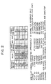
- FIG. 2 is a table showing different gauge wires for different alloys used in the present invention.
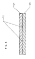
- FIG. 3 is a cross sectional view of a heater of the present invention.
- FIG. 4 is a cross sectional view of one layer of the heater of the present invention.
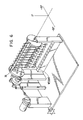
- FIG. 5 is an illustration of a scrape abrasion test machine.
- FIG. 6 is an illustration of a flexure test fixture.
- the present invention provides heaters for placing on rigid fluid lines or hoses. These heaters are capable of withstanding impact.
- the present invention also provides heaters that are capable of withstanding flexure so that, in the event the heaters are moved in a back and forth motion, the wirings will not break inside the heaters thereby causing the heaters to malfunction. If the heaters do malfunction, the hoses or rigid lines will freeze thereby causing overflow. In the aircraft industry this is especially critical in providing safety to passengers, flight staff and crew. This invention is also useful in other industries, especially when it becomes critical to prevent lines or hoses from freezing.
- FIG. 1 is a schematic diagram of the present invention.
- Heater 10 includes a resistance wire 12 that runs through the heater 10.
- the resistance wire 12 has a resistance R and can have in some embodiments a thermostat 14.
- Thermostat 14 is used to control the temperature.
- Each of the lead wires 16 and 18 of the resistance wire 12 are attached to a power source through lines 20 and 22.
- the resistance wire 12 in some embodiments of the invention can be wound around an electrically non-conductive core.
- the core can be a fiberglass core and the resistance wire 12 may be helically wound around the fiberglass core to obtain a desired resistance.
- a high gauge wire titanium wire
- a wire having a wire gauge of 48 can be used in some instances.
- FIG. 2 is a table showing different gauge wires for different alloys used in the present invention. Choosing a high gauge wire as shown for example in the table provided in FIG. 2 will provide a heater that can withstand movement causing the heater to flex or bend. The wire will not break but will be able to stay in tact through such movement.
- a wire with a lot of turns is desirable in some embodiments of the invention.
- the resistance of wire as it gets smaller in general gets larger.
- the load of the wire can be reduced by providing more turns per inch.
- the resistance of the wire can then be controlled with the number of turns providing proper resistance for proper heating.
- the wire used in the heater in some cases is of a very high gage/small diameter to minimize deleterious effects of repeated flexure of the heater. In some cases the heater will require a low resistance (as shown in FIG. 2 ).
- One solution is to use a single low gage/large diameter wire to save costs associated with material and assembly effort.
- several small diameter wires connected electrically in parallel are implemented to attain the same low resistance requirement, but also provide enhanced flexure endurance by using higher gage/small diameter wire. In this way flexure performance is maintained while achieving a low resistance factor.
- FIG. 3 is a cross sectional view of the invention as illustrated in FIG. 1 .
- the invention includes a cover, upper layer 24, and a base, lower layer 26. Resistance wire 12 is sandwiched between the upper layer 24 and the lower layer 26.
- the upper and lower layers 24,26 can be made from reinforced fiberglass. In some cases the upper and lower layers 24,26 can be made from silicon and VectranTM. This type of material will provide protection from abrasion or other forces which may cause the heater to malfunction.
- FIG. 4 is an illustration of either the upper layer 24 or the lower layer 26.
- the outer layer 28 is a protective layer and can be made out of a material which can endure and withstand abrasion.
- the outer layer 28 in some cases is made of Vectran TM which is a polyester-polyarylate fiber. In other embodiments of the invention this outer layer 28 can be a liquid crystal polymer fiber.
- the middle layer 30 can be a cured silicone, while layer 32 can be an uncured silicone layer (before assembly processing).
- a release liner 34 in some embodiments of the invention, can be attached to layer 32 so that it can be peeled back for use. One purpose for having a release liner is to protect the uncured silicone layer 32 (before assembly processing).
- the thickness of layer 28 is 0.495 mm (.0195 inches)
- layer 30 is 0.152 mm (.0.06 inches)
- layer 32 is 0.356 mm (.014 inches)
- layer 34 is (.003 inches) 76 ⁇ m.
- the resistance wire 12 which is helically wound around the electrically non-conductive core, is placed between upper layer 24 and lower layer 26 so that the layers 32 of uncured silicone are facing one another once the release liner 34 is peeled back to expose the uncured silicone.
- the upper layer 24 and the lower layer 26 along with the helically wound resistance wire sandwiched between the upper and lower layers 24,26 are then put through a vulcanization process which cures the upper and lower layers such that it provides an assembly that cannot be taken apart thereby creating a unitary piece.
- a layer of uncured silicone is used in order to lay the element wire in place long enough to complete the assembly process.
- the element wire in some cases is rolled into the uncured silicone layer since the rubber is soft.
- the wire becomes embedded and is not disturbed throughout the balance of the assembly and curing process.
- the cured silicone resides beneath the uncured silicone and is in place to prevent the heater element wire from protruding through to the outside surface. If this happened the protrusion would serve as a leak path for a very important electrical parameter that must be met at the top assembly level, dielectric withstanding voltage (DWV).
- the cured layer and the uncured layer after curing both contribute to dielectric strength as the silicone base material has an inherent dielectric strength expressed in volts per mil thickness.
- the heater element wire in the final product is thus embedded in cured silicone.
- the resultant heater provides for a straight ribbon heater which can be installed straight onto the surface of a rigid fluid line or hose along its axis without damage from flexure or abrasion.
- the heater can be wound around a rigid fluid line or hose.
- the heater can simply be attached to the rigid fluid line or hose using an adhesive or attachment mechanism.
- FIG. 5 is an illustration of a scrape abrasion test machine used to test for abrasion resistance.
- a test specimen 36 the heater, is placed on a drum 38.
- the test specimen 36 is clamped onto the drum 38 with clamps 40.
- a weight 42 weighs down scrape blade 44.
- Scrape blade 44 is put in contact with the specimen 36.
- An armature 46 is attached to the weight 42 and scrape blade 44 at one end and to a scrape cycle counter 48 at another end.
- An actuator 50 is connected to the drum 38.
- the scrape cycle rate is set to approximately 60 cycles per minute.
- the scrape path is set to 50.8 +/- 7.62 mm (2.00 +/- 0.3 inches) in length on test specimen 36.
- the scrape blade 44 is made of tungsten carbide Kennametal grade K701 having a Rockwell hardness A92, minimum, and a chromium cobalt binder. The dimensions of scrape blade 44 can vary.
- scrape blade 44 has a width of 31.8 +/- 6.35 mm (1.25 +/- 0.25 inches), a length of 50.8 +/- 7.62 mm (2.0 +/- 0.3 inches), a thickness of 8.89 +/- 0.762 mm (0.35 +/- 0.03 inches) and a blade edge of 45 +/- 2 degrees and a 127 +/- 25 ⁇ m (0.005+/- 0.001 inch) radius.
- Weight 42 can vary. In one embodiment of the invention weight 42 is 0.454 +/- 0.014 kg (1.00 +/- 0.03 pounds). The number of specimens used vary depending on the qualification standards. In some cases 6 specimens are required for qualification testing, each specimen being 15 inches in length. For conformance testing 2 specimens may be needed, each specimen being 15 inches in length.
- the qualification test procedure can be set up so that the scrape abrasion test machine scrapes the specimen until a damage condition occurs when the scrapped area of the specimen is inspected with a 10X magnification. In one embodiment of the invention this is when the resistance wire shows through the outer cover. The number of test cycles performed is recorded once this damage condition occurs. This procedure is repeated for each of the six specimens.
- the average number of scrape cycles before damage is 131,720 cycles. It is noted that one scrape cycle consists of two scrape strokes.
- FIG. 6 is an illustration of a flexure test fixture that is used to test flexure endurance.
- a minimum of three specimens 36 are placed between mandrels 52.
- Each of the specimens 36 are connected to an electrical circuit that will provide an indication when the conductors within the heater break.
- the specimen is twisted and flexed at a uniform rate of 18 +/- 2 cycles per minute in one embodiment of the invention, where a cycle is defined as movement from -90 degrees to 0 to +90 degrees or as specified.
- the number of cycles for the conductors is recorded until a break is indicated or until completion of the number of cycles required by the product specification.
- the condition of the insulation is also recorded.
- tests are performed under specific temperatures and environmental conditions.
- the average number of cycles before damage is 13,754 cycles using four parallel conductor heater elements and 68,753 cycles using a single conductor heater element.
Landscapes
- Engineering & Computer Science (AREA)
- General Engineering & Computer Science (AREA)
- Mechanical Engineering (AREA)
- Resistance Heating (AREA)
- Vending Machines For Individual Products (AREA)
- Air-Conditioning For Vehicles (AREA)
Abstract
Description
- This application claims priority to the provisional
U.S. Patent Application No. 60/549,912 filed March 5, 2004 U.S. Patent Application No. 10/935,149 filed September 8.2004 No. 7,176,401 . - The present invention relates to heaters. More particularly the invention relates to heaters placed on a surface of a rigid fluid line or hose. One application of the technology is to use these types of heaters in an airframe to provide a heat source for freeze protection of waste and potable water hoses and rigid fluid lines. The present invention, however, can be used in other areas known to those skilled in the art.
- Heaters are used to provide freeze protection for commercial transport aircraft, regional jet, and corporate and business jet markets with the principal focus on potable and waste water systems. Applications in which theses heaters can be used are waste ducting, potable water hose and plumbing, waste water drain lines, flush/fill and potable water fittings, water and hydraulic valves, and water tanks and heated vessels.
- In
US 3,031,739 is disclosed an electric heating unit with a resistor conductor wire embedded within a cured silicone layer which is disposed between three upper layers and three lower layers. These upper and lower layers are being bond together by cured silicone layers. The upper and lower layers are made of glass fiber. Thus, the resistive wire (11) is sandwiched between a five-layer base and a five-layer cover. - Document
US 2,719,907 discloses a heating tape, whereby the tape being in the form of a flat elongated strip which may be wrapped about an object to be heated. The tape includes a central core that comprises the heating element which is sandwiched between two layers on each side. The central core is made of a rubber supporting strip. The layers are made of fiber glass and the covering layers are made of rubber coating. -
US 5,883,364 discloses a clean room heating jacket consisting of a flexible heating element which comprises several elongated, heat-generating core wires, an insulative layer wrapped around the core wires, a first layer of thread wrapped around the insulative layer, a ground conductor wrapped around the first layer of thread, a second layer of thread wrapped around the ground conductor and a third layer of thread wrapped around the second layer of thread, whereby the heating element is formed into serpentine loops and a fourth layer or a set of threads is intertwined between the loops to hold them in spaced relation to one another. The whole layer system is wrapped around a processing vessel to be heated. - There is a need in the industry for heaters that are durable and capable of withstanding scrape abrasion, cut through, twist and flexure test to ensure that the heaters do not malfunction. If the heaters do malfunction, the hoses or rigid lines will freeze thereby causing overflow. There is also a need for these heaters to be light weight and non-flammable to meet aircraft requirements.
- There is thus a need for a heater which is more easily attached to a surface and that can withstand the stress and strains of flexure and abrasion.
- In one embodiment of the invention the heater includes a base having an outer base layer and a middle base layer attached to said outer base layer. An inner base layer is attached to the middle base layer. A resistance wire is wound around an electrically non-conductive core and located on the inner base layer. A cover is provided that covers the resistance wire. The cover has an inner cover layer covering the resistance wire, a middle cover layer attached to the inner cover layer, and an outer cover layer.
- The outer base and the outer cover are made of a polyester-polyarylate fiber in one embodiment of the invention.
- The outer base layer and the outer cover layer can, alternatively, be made of a liquid crystal polymer fiber in another embodiment of the invention.
- The middle base layer and the middle cover layer are silicone in one embodiment of the invention.
- The middle base layer and the middle cover layer are cured silicone in another embodiment of the invention.
- The inner base layer and the inner cover layer are silicone in one embodiment of the invention.
- The inner base layer and the inner cover layer are uncured silicone in another embodiment of the invention (before processing).
- In another embodiment of the invention, the electrically non-conductive core is a fiberglass core.
- The invention can further include a thermostat connected to the resistance wire in another embodiment of the invention.
- In another embodiment of the invention, lead wires are connected to the resistance wires.
- The resistance wire, in an alternate embodiment of the invention, is helically wound around the electrically non-conductive core.
- The base and cover, in another embodiment of the invention, are attached by heating.
- In an alternate embodiment of the invention, the base and cover are attached through vulcanization.
- The base and cover, in another embodiment of the invention, are attached by peroxide cure reaction of the base and cover and heating the base and cover.
- The invention in an alternate embodiment is a method for making a heater including providing a base having: an outer base layer; a middle base layer attached to the outer base layer; and an inner base layer attached to the middle base layer. A resistance wire wound around an electrically non-conductive core is provided on the inner base layer; and a cover is provided that covers the resistance wire. The cover has an inner cover layer covering the inner base layer and the heating element (a.k.a. resistance wire); a middle cover layer attached to the inner cover layer; and an outer cover layer. The cover is attached to the base.
- In one embodiment of the invention the cover and the base are attached through heat treatment.
- In another embodiment of the invention the cover and base are attached by peroxide cure reaction of the inner base layer and the inner cover layer; and heat treating the cover and the base.
- In an alternate embodiment of the invention the cover and the base are attached by vulcanizing the cover and the base.
- In an alternate embodiment of the invention a system for heating includes a means for providing a base having: an outer base layer, a middle base layer attached to the outer base layer; and an inner base layer attached to the middle base layer. The system further includes a means for providing a resistance wire wound around an electrically non-conductive core on the inner base layer, and a means for providing a cover that covers the inner base layer and the heating element (a.k.a. resistance wire). The cover has an inner cover layer covering the resistance wire; a middle cover layer attached to the inner cover layer, and an outer cover layer. The system further includes a means for attaching the cover to the base.
- In one embodiment of the invention, the means for attaching includes a means for heat treating the cover and the base.
- In an alternate embodiment of the invention, the means for attaching includes a peroxide cure reaction of the inner base layer and the inner cover layer; and a means for heat treating the cover and the base.
- In another embodiment of the invention, the means for attaching includes vulcanizing the cover and the base.
- There has thus been outlined, rather broadly, the more important features of the invention in order that the detailed description thereof that follows may be better understood, and in order that the present contribution to the art may be better appreciated. There are, of course, additional features of the invention that will be described below and which will form the subject matter of the claims appended hereto.
- In this respect, before explaining at least one embodiment of the invention in detail, it is to be understood that the invention is not limited in its application to the details of construction and to the arrangements of the components set forth in the following description or illustrated in the drawings. The invention is capable of other embodiments and of being practiced and carried out in various ways. Also, it is to be understood that the phraseology and terminology employed herein, as well as the abstract included below, are for the purpose of description and should not be regarded as limiting.
- As such, those skilled in the art will appreciate that the conception upon which this disclosure is based may readily be utilized as a basis for the designing of other structures, methods and systems for carrying out the several purposes of the present invention. It is important, therefore, that the claims be regarded as including such equivalent constructions insofar as they do not depart from the spirit and scope of the present invention.
-
FIG. 1 is a schematic view of a heater of the present invention. -
FIG. 2 is a table showing different gauge wires for different alloys used in the present invention. -
FIG. 3 is a cross sectional view of a heater of the present invention. -
FIG. 4 is a cross sectional view of one layer of the heater of the present invention. -
FIG. 5 is an illustration of a scrape abrasion test machine. -
FIG. 6 is an illustration of a flexure test fixture. - The present invention provides heaters for placing on rigid fluid lines or hoses. These heaters are capable of withstanding impact. The present invention also provides heaters that are capable of withstanding flexure so that, in the event the heaters are moved in a back and forth motion, the wirings will not break inside the heaters thereby causing the heaters to malfunction. If the heaters do malfunction, the hoses or rigid lines will freeze thereby causing overflow. In the aircraft industry this is especially critical in providing safety to passengers, flight staff and crew. This invention is also useful in other industries, especially when it becomes critical to prevent lines or hoses from freezing.
-
FIG. 1 is a schematic diagram of the present invention.Heater 10 includes aresistance wire 12 that runs through theheater 10. Theresistance wire 12 has a resistance R and can have in some embodiments athermostat 14.Thermostat 14 is used to control the temperature. Each of thelead wires resistance wire 12 are attached to a power source throughlines - The
resistance wire 12 in some embodiments of the invention can be wound around an electrically non-conductive core. The core can be a fiberglass core and theresistance wire 12 may be helically wound around the fiberglass core to obtain a desired resistance. It has been found that using a high gauge wire (thin wire) provides for a smaller moment of flexure. Thus, in some embodiments of the invention, it is desirable to use a high gauge wire. A wire having a wire gauge of 48 can be used in some instances.FIG. 2 is a table showing different gauge wires for different alloys used in the present invention. Choosing a high gauge wire as shown for example in the table provided inFIG. 2 will provide a heater that can withstand movement causing the heater to flex or bend. The wire will not break but will be able to stay in tact through such movement. - A wire with a lot of turns is desirable in some embodiments of the invention. The resistance of wire as it gets smaller in general gets larger. The load of the wire can be reduced by providing more turns per inch. The resistance of the wire can then be controlled with the number of turns providing proper resistance for proper heating.
- In some embodiments of the invention, special consideration is given to ensure that the wire will withstand conditions leading to repeated flexure of the heater. The wire used in the heater in some cases is of a very high gage/small diameter to minimize deleterious effects of repeated flexure of the heater. In some cases the heater will require a low resistance (as shown in
FIG. 2 ). One solution is to use a single low gage/large diameter wire to save costs associated with material and assembly effort. However in other embodiments of the invention, several small diameter wires connected electrically in parallel are implemented to attain the same low resistance requirement, but also provide enhanced flexure endurance by using higher gage/small diameter wire. In this way flexure performance is maintained while achieving a low resistance factor. -
FIG. 3 is a cross sectional view of the invention as illustrated inFIG. 1 . The invention includes a cover,upper layer 24, and a base,lower layer 26.Resistance wire 12 is sandwiched between theupper layer 24 and thelower layer 26. The upper andlower layers lower layers -
FIG. 4 is an illustration of either theupper layer 24 or thelower layer 26. Each of these layers can be made of identical material. Theouter layer 28 is a protective layer and can be made out of a material which can endure and withstand abrasion. Theouter layer 28 in some cases is made of Vectran ™ which is a polyester-polyarylate fiber. In other embodiments of the invention thisouter layer 28 can be a liquid crystal polymer fiber. Themiddle layer 30 can be a cured silicone, whilelayer 32 can be an uncured silicone layer (before assembly processing). Arelease liner 34, in some embodiments of the invention, can be attached to layer 32 so that it can be peeled back for use. One purpose for having a release liner is to protect the uncured silicone layer 32 (before assembly processing). In one embodiment of the invention, the thickness oflayer 28 is 0.495 mm (.0195 inches),layer 30 is 0.152 mm (.0.06 inches),layer 32 is 0.356 mm (.014 inches) andlayer 34 is (.003 inches) 76 µm. - In constructing the present invention, the
resistance wire 12, which is helically wound around the electrically non-conductive core, is placed betweenupper layer 24 andlower layer 26 so that thelayers 32 of uncured silicone are facing one another once therelease liner 34 is peeled back to expose the uncured silicone. - The
upper layer 24 and thelower layer 26 along with the helically wound resistance wire sandwiched between the upper andlower layers - A layer of uncured silicone is used in order to lay the element wire in place long enough to complete the assembly process. The element wire in some cases is rolled into the uncured silicone layer since the rubber is soft. The wire becomes embedded and is not disturbed throughout the balance of the assembly and curing process. The cured silicone resides beneath the uncured silicone and is in place to prevent the heater element wire from protruding through to the outside surface. If this happened the protrusion would serve as a leak path for a very important electrical parameter that must be met at the top assembly level, dielectric withstanding voltage (DWV). The cured layer and the uncured layer after curing both contribute to dielectric strength as the silicone base material has an inherent dielectric strength expressed in volts per mil thickness. The heater element wire in the final product is thus embedded in cured silicone.
- The resultant heater provides for a straight ribbon heater which can be installed straight onto the surface of a rigid fluid line or hose along its axis without damage from flexure or abrasion. However, in some embodiments of the invention the heater can be wound around a rigid fluid line or hose. In other embodiments, the heater can simply be attached to the rigid fluid line or hose using an adhesive or attachment mechanism.
- Vigorous tests were performed on the resultant heater in the areas of abrasion resistance and flexure endurance. The heater performed phenomenally in each of these areas.
-
FIG. 5 is an illustration of a scrape abrasion test machine used to test for abrasion resistance. Atest specimen 36, the heater, is placed on adrum 38. Thetest specimen 36 is clamped onto thedrum 38 withclamps 40. Aweight 42 weighs downscrape blade 44.Scrape blade 44 is put in contact with thespecimen 36. Anarmature 46 is attached to theweight 42 andscrape blade 44 at one end and to ascrape cycle counter 48 at another end. Anactuator 50 is connected to thedrum 38. - In one embodiment of the invention the scrape cycle rate is set to approximately 60 cycles per minute. The scrape path is set to 50.8 +/- 7.62 mm (2.00 +/- 0.3 inches) in length on
test specimen 36. Thescrape blade 44 is made of tungsten carbide Kennametal grade K701 having a Rockwell hardness A92, minimum, and a chromium cobalt binder. The dimensions ofscrape blade 44 can vary. In one embodiment of theinvention scrape blade 44 has a width of 31.8 +/- 6.35 mm (1.25 +/- 0.25 inches), a length of 50.8 +/- 7.62 mm (2.0 +/- 0.3 inches), a thickness of 8.89 +/- 0.762 mm (0.35 +/- 0.03 inches) and a blade edge of 45 +/- 2 degrees and a 127 +/- 25 µm (0.005+/- 0.001 inch) radius. -
Weight 42 can vary. In one embodiment of theinvention weight 42 is 0.454 +/- 0.014 kg (1.00 +/- 0.03 pounds). The number of specimens used vary depending on the qualification standards. In somecases 6 specimens are required for qualification testing, each specimen being 15 inches in length. Forconformance testing 2 specimens may be needed, each specimen being 15 inches in length. - The qualification test procedure can be set up so that the scrape abrasion test machine scrapes the specimen until a damage condition occurs when the scrapped area of the specimen is inspected with a 10X magnification. In one embodiment of the invention this is when the resistance wire shows through the outer cover. The number of test cycles performed is recorded once this damage condition occurs. This procedure is repeated for each of the six specimens.
- In one embodiment of the invention, the average number of scrape cycles before damage is 131,720 cycles. It is noted that one scrape cycle consists of two scrape strokes.
-
FIG. 6 is an illustration of a flexure test fixture that is used to test flexure endurance. In one embodiment of the invention a minimum of threespecimens 36 are placed betweenmandrels 52. Each of thespecimens 36 are connected to an electrical circuit that will provide an indication when the conductors within the heater break. The specimen is twisted and flexed at a uniform rate of 18 +/- 2 cycles per minute in one embodiment of the invention, where a cycle is defined as movement from -90 degrees to 0 to +90 degrees or as specified. The number of cycles for the conductors is recorded until a break is indicated or until completion of the number of cycles required by the product specification. The condition of the insulation is also recorded. In other embodiments of the invention, tests are performed under specific temperatures and environmental conditions. In one embodiment of the invention the average number of cycles before damage is 13,754 cycles using four parallel conductor heater elements and 68,753 cycles using a single conductor heater element.
Claims (22)
- A heater (10) consisting of:a base (26) consisting of:an outer base layer (28) comprising a fiber-reinforced composite selected from the group consisting of a polyester-polyarylate fiber and a liquid crystal polymer fiber;a middle base layer (30) of cured silicone attached to said outer base layer (28); andan inner base layer (32) of silicone that is uncured before assembly of the heater (10), attached immediately adjacent to said middle base layer (30);a resistance wire (12) that it at least partially embedded into said inner base layer (32); anda cover (24) that covers said resistance wire (12), said cover (24) consisting of:an inner cover layer (32) of silicone that is uncured before assembly of the heater (10) covering said resistance wire (12) and said inner base layer (32);a middle cover layer (30) of cured silicone attached immediately adjacent to said inner cover layer (32); andan outer cover layer (28) comprising the fiber-reinforced composite selected from the group consisting of a polyester-polyarylate fiber and a liquid crystal polymer fiber attached to said middle cover layer (30).
- The heater (10) as recited in claim 1
characterized in that
said electrically non-conductive core (13) is a fiberglass core. - The heater (10) as recited in claim 1
characterized in that
further comprising a thermostat (14) connected to said resistance wire (12). - The heater (10) as recited in claim 1
characterized in that
further comprising lead wires (16) connected to the ends of said resistance wires (12). - The heater (10) as recited in claim 1
characterized in that
said resistance wire (12) is helically wound around said electrically non-conductive core (13). - The heater (10) as recited in claim 1
characterized in that
said base (26) and cover (24) are attached by heat and pressure during assembly of the heater (10). - The heater (10) as recited in claim 1
characterized in that
said base (26) and cover (24) are attached through vulcanization during assembly of the heater (10). - The heater (10) as recited in claim 1
characterized in that
said base (26) and cover (24) are attached by peroxide cure reaction and heat during assembly of the heater (10). - The heater (10) as recited in claim 1
characterized in that
said resistance wire (12) comprises a plurality of resistance wires in parallel with one another. - A method for making a heater (10)
characterized in that
consisting of:forming a base (10), wherein the forming a base (26) consists of:forming an outer base layer (28) comprising a first fiber-reinforced composite selected from the group consisting of a polyester-polyarylate fiber and a liquid crystal polymer fiber;attaching a middle base layer (30) to said outer base layer (28), said middle base layer (30) comprising cured silicone; andattaching an inner base layer (32) immediately adjacent to said middle base layer (30), said inner base layer (32) comprising uncured silicone;embedding a resistance wire (12) at least partially into the uncured silicone of said inner base layer (32);forming a cover layer (24), wherein the forming a cover layer (24)
consists of:forming an inner cover layer (32) of uncured silicone;attaching a middle cover layer (30) of cured silicone to said inner cover layer (32); andattaching an outer cover layer (28) immediately adjacent to said middle cover layer (30), the outer cover layer (38) comprising a second fiber-reinforced composite comprising selected from the group consisting of a polyester-polyarylate fiber and a liquid crystal polymer fiber; andcovering the resistance wire (12) with the cover layer (24), wherein the covering the resistance wire (12) comprises attaching said inner cover layer (32) to said inner base layer (32). - The method as recited in claim 10
characterized in that
said attaching said inner cover layer (32) to said inner base layer (32) comprises heat treating said inner cover layer (32) and said inner base layer (32). - The method as recited in claim 10
characterized in that
said attaching said inner cover layer (32) to said inner base layer (32) comprises:peroxide cure reaction of said inner base layer (32) and said inner cover layer (32); andheat treating said inner cover layer (32) and said inner base layer (32). - The method as recited in claim 10
characterized in that
said attaching said inner cover layer (32) to said inner baser layer (32) comprises vulcanizing said inner cover layer (32) and said inner base layer (32). - The method as recited in claim 10
characterized in that
the embedding a resistance wire (12) further comprises embedding a plurality of resistance wires in parallel with one another. - A system for heating
characterized in that
consisting of:means for providing a base (26) consists of:an outer base layer (28) comprising a fiber-reinforced composite selected from the group consisting of a polyester-polyarylate fiber and a liquid crystal polymer fiber;a middle base layer (30) of cured silicone attached to said outer base layer (28); andan inner base layer (32) attached immediately adjacent to said middle base layer (30), said inner baser layer (32) comprising silicone that is uncured before assembly of the heater (10);means for providing a resistance wire (12) that is at least partially embedded into the uncured silicone of said inner base layer (32) during assembly of the heater (10); andmeans for providing a cover (24) that covers said resistance wire (12), said cover (24) consisting of:an inner cover layer (32) covering said resistance wire (12), said inner cover layer (32) comprising silicone that is uncured before assembly of the heater (10);a middle cover layer (30) of cured silicone attached immediately adjacent to said inner cover layer (32); andan outer cover layer (28) comprising the fiber-reinforced composite selected from the group consisting of a polyester-polyarylate fiber and a liquid crystal polymer fibers attached to said middle cover layer (30); and means for attaching said cover (24) to said base (26) via said inner base layer (32) and said inner cover layer (32). - The system as recited in claim 15
characterized in that
said means for attaching comprises a means for heat treating said cover (24) and said base (26). - The system as recited in claim 15
characterized in that
said means for attaching comprises:peroxide cure reaction of said inner base layer (32) and said inner cover layer (32); andmeans for heat treating said cover (24) and said base (26). - The system as recited in claim 15
characterized in that
said means for attaching comprises vulcanizing said cover (24) and said base (26). - The system as recited in claim 15
characterized in that
wherein said means for providing a resistance wire (12) comprises providing a plurality of resistance wires in parallel with one another. - The heater (10) as recited in claim 1
characterized in that
further comprising an electrically non-conductive core (13), wherein said resistance wire (12) is wound around said core (13). - The heater (10) as recited in claim 1
characterized in that
said inner cover layer (32)is attached to said inner base (32) layer during assembly of the heater (10). - The heater (10) as recited in claim 1
characterized in that
said resistance wire (12) is at least partially embedded into the uncured silicone of said inner cover layer (32) during assembly of the heater (10).
Applications Claiming Priority (3)
| Application Number | Priority Date | Filing Date | Title |
|---|---|---|---|
| US54991204P | 2004-03-05 | 2004-03-05 | |
| US10/935,149 US7176421B2 (en) | 2004-03-05 | 2004-09-08 | Straight ribbon heater |
| PCT/US2005/004523 WO2005094126A1 (en) | 2004-03-05 | 2005-02-15 | Straight ribbon heater |
Publications (2)
| Publication Number | Publication Date |
|---|---|
| EP1721491A1 EP1721491A1 (en) | 2006-11-15 |
| EP1721491B1 true EP1721491B1 (en) | 2008-04-09 |
Family
ID=34915653
Family Applications (1)
| Application Number | Title | Priority Date | Filing Date |
|---|---|---|---|
| EP05723008A Expired - Lifetime EP1721491B1 (en) | 2004-03-05 | 2005-02-15 | Straight ribbon heater |
Country Status (6)
| Country | Link |
|---|---|
| US (1) | US7176421B2 (en) |
| EP (1) | EP1721491B1 (en) |
| AT (1) | ATE392121T1 (en) |
| DE (1) | DE602005005960T2 (en) |
| ES (1) | ES2306118T3 (en) |
| WO (1) | WO2005094126A1 (en) |
Families Citing this family (6)
| Publication number | Priority date | Publication date | Assignee | Title |
|---|---|---|---|---|
| CN102912510A (en) * | 2008-05-28 | 2013-02-06 | 瑟尔瑞株式会社 | Electrically conductive pad and a production method thereof |
| CN104290914A (en) | 2008-09-23 | 2015-01-21 | 飞行环境公司 | Remote device control and power supply |
| KR101092407B1 (en) * | 2009-04-16 | 2011-12-09 | 박태환 | Radiating plate for cordless hair iron and cordless hair iron |
| TWM416959U (en) * | 2011-04-25 | 2011-11-21 | Hsin Yung Chien Co Ltd | Continuous silicone thermoelectric sheet |
| DE102015222799A1 (en) * | 2015-11-19 | 2017-05-24 | Robert Bosch Gmbh | Method for producing a heating and a heating device, heating and heating device |
| US11856661B1 (en) * | 2021-02-24 | 2023-12-26 | Automated Assembly Corporation | Flexible heating element |
Family Cites Families (37)
| Publication number | Priority date | Publication date | Assignee | Title |
|---|---|---|---|---|
| US2683673A (en) | 1952-03-10 | 1954-07-13 | Electrofilm Corp | Film-type heating element |
| US2719907A (en) | 1952-04-19 | 1955-10-04 | Connecticut Hard Rubber Co | Heating tape and method of making same |
| US2710909A (en) | 1953-11-16 | 1955-06-14 | Richard W Logan | Electric heating element |
| US3031739A (en) | 1958-06-02 | 1962-05-01 | Wiegand Co Edwin L | Electric heating units and method of making the same |
| BE790189A (en) * | 1971-11-01 | 1973-02-15 | Gen Electric | HEATING ELEMENT BY ELECTRICAL RESISTANCE |
| US3861029A (en) * | 1972-09-08 | 1975-01-21 | Raychem Corp | Method of making heater cable |
| CA1089904A (en) * | 1978-02-03 | 1980-11-18 | Joseph M. Bender | Radiant therapeutic heater |
| JPS5541646A (en) * | 1978-09-18 | 1980-03-24 | Shinetsu Polymer Co | Hollow tubular heater |
| NZ193661A (en) * | 1979-05-10 | 1983-06-17 | Sunbeam Corp | Heating element conductive and ptc material |
| US4346277A (en) * | 1979-10-29 | 1982-08-24 | Eaton Corporation | Packaged electrical heating element |
| US4309597A (en) * | 1980-05-19 | 1982-01-05 | Sunbeam Corporation | Blanket wire utilizing positive temperature coefficient resistance heater |
| JPS57157096U (en) * | 1981-03-27 | 1982-10-02 | ||
| US4427877A (en) * | 1981-09-28 | 1984-01-24 | Raychem Corporation | Printing on low surface energy polymers |
| GB2180857B (en) * | 1985-07-19 | 1990-02-14 | Showa Electric Wire & Cable Co | Heat resistant prepreg and method for production thereof |
| US4695703A (en) * | 1986-04-25 | 1987-09-22 | Amark Industries, Inc. | Flexible blanket heater |
| US5138684A (en) | 1991-01-14 | 1992-08-11 | W. L. Gore & Associates, Inc. | High-strength isolated core cable |
| BE1005729A3 (en) * | 1992-04-13 | 1993-12-28 | Nestor Martin Sa | Heat source of dressing. |
| US5408071A (en) * | 1992-06-11 | 1995-04-18 | Atd Corporation | Electric heater with heat distributing means comprising stacked foil layers |
| JP2747960B2 (en) * | 1992-10-13 | 1998-05-06 | 東京特殊電線株式会社 | Heater wire with thermosensitive layer that also serves as fusion fault |
| EP0811892A4 (en) * | 1995-12-25 | 1999-11-17 | Nippon Petrochemicals Co Ltd | Laminate structure for heating |
| US5883364A (en) | 1996-08-26 | 1999-03-16 | Frei; Rob A. | Clean room heating jacket and grounded heating element therefor |
| US6018137A (en) | 1996-09-03 | 2000-01-25 | Reiff; Robert P. | Apparatus and method for heating cold engines |
| US6084206A (en) * | 1997-05-28 | 2000-07-04 | The Boeing Company | Internally temperature controlled heat blanket |
| US5910266A (en) * | 1997-05-28 | 1999-06-08 | The B.F. Goodrich Company | Helical electrical heater |
| US5938963A (en) * | 1997-06-02 | 1999-08-17 | Tanis; Peter G. | Gasket shaped heater |
| US6021523A (en) * | 1998-07-20 | 2000-02-08 | Lakeland Industries | Heat and abrasion resistant woven glove |
| JP4191308B2 (en) * | 1999-03-16 | 2008-12-03 | 株式会社クラレ | Laminated insulation and method for producing the same |
| US6563094B2 (en) * | 1999-05-11 | 2003-05-13 | Thermosoft International Corporation | Soft electrical heater with continuous temperature sensing |
| US6263158B1 (en) * | 1999-05-11 | 2001-07-17 | Watlow Polymer Technologies | Fibrous supported polymer encapsulated electrical component |
| US6420682B1 (en) * | 1999-11-03 | 2002-07-16 | Newhome Bath & Mirror, Inc. | Fogless mirror for a bathroom shower and bathtub surround |
| US6668535B2 (en) * | 1999-12-20 | 2003-12-30 | Du Pont-Toray Co., Ltd. | Heat-resistant crimped yarn |
| DE10036059B4 (en) | 2000-07-25 | 2007-04-12 | Horn GmbH Fabrik für Metall-, Silicon-, und Teflonverarbeitung | Electric heating tape |
| WO2003037621A2 (en) * | 2001-10-31 | 2003-05-08 | 3M Innovative Properties Company | Bonding of a fluoropolymer layer to a substrate |
| AU2003236317A1 (en) * | 2002-03-29 | 2003-10-13 | Du Pont-Toray Company, Ltd. | Composite comprising heat-resistant fiber and siloxane polymer |
| JP2003332028A (en) * | 2002-05-09 | 2003-11-21 | Mitsubishi Pencil Co Ltd | Resistance heating element and manufacturing method thereof |
| US7198742B2 (en) * | 2003-12-30 | 2007-04-03 | Kimberly-Clark Worldwide, Inc. | Apparatus and method for deforming sheet material |
| JP4479238B2 (en) * | 2004-01-08 | 2010-06-09 | 住友化学株式会社 | Resin impregnated substrate |
-
2004
- 2004-09-08 US US10/935,149 patent/US7176421B2/en not_active Expired - Lifetime
-
2005
- 2005-02-15 DE DE602005005960T patent/DE602005005960T2/en not_active Expired - Lifetime
- 2005-02-15 WO PCT/US2005/004523 patent/WO2005094126A1/en not_active Ceased
- 2005-02-15 AT AT05723008T patent/ATE392121T1/en not_active IP Right Cessation
- 2005-02-15 EP EP05723008A patent/EP1721491B1/en not_active Expired - Lifetime
- 2005-02-15 ES ES05723008T patent/ES2306118T3/en not_active Expired - Lifetime
Also Published As
| Publication number | Publication date |
|---|---|
| US7176421B2 (en) | 2007-02-13 |
| EP1721491A1 (en) | 2006-11-15 |
| DE602005005960T2 (en) | 2009-05-07 |
| WO2005094126A1 (en) | 2005-10-06 |
| ATE392121T1 (en) | 2008-04-15 |
| ES2306118T3 (en) | 2008-11-01 |
| DE602005005960D1 (en) | 2008-05-21 |
| US20050194378A1 (en) | 2005-09-08 |
Similar Documents
| Publication | Publication Date | Title |
|---|---|---|
| Todoroki et al. | Matrix crack detection of CFRP using electrical resistance change with integrated surface probes | |
| US10167550B2 (en) | Multi-functional composite structures | |
| US10368401B2 (en) | Multi-functional composite structures | |
| US3559693A (en) | Windable flexible shaft capable of withstanding high tractive forces and torsional stresses | |
| CA2137287C (en) | Corrosion resistant cable | |
| US9046207B2 (en) | Line for transporting a fluid containing a hydrocarbon, and method for producing such a line | |
| US7740452B2 (en) | Highly extensible power and/or signal transmission cable as well as rotor blade with such a cable | |
| EP2661754A2 (en) | Aluminum alloy conductor composite reinforced for high voltage overhead power lines | |
| US7176421B2 (en) | Straight ribbon heater | |
| EP1367859A2 (en) | Heater for aircraft potable water tank | |
| US20080283272A1 (en) | Self-healing cable for extreme environments | |
| TWI793198B (en) | Sensor device and measurement method | |
| KR20190073307A (en) | Pfa tube heater with flexible heating elements | |
| EP3592107B1 (en) | Heated floor panels | |
| US4236109A (en) | Dielectric monitored composite assembly | |
| WO2007136260A1 (en) | Heated aerodynamic profile for composite structures | |
| US11499724B2 (en) | Heated floor panels | |
| US8630534B2 (en) | Heating system and component with such a heating system | |
| US4841124A (en) | Strain-resistant heated helicopter rotor blade | |
| EP0371115A1 (en) | Marine antifouling. | |
| US5330809A (en) | Thermal protection sleeve for reducing overheating of wire bundles utilized in aircraft application | |
| WO2021232026A1 (en) | Composite strength members for overhead electrical cables and methods for interrogation of same | |
| US20050194376A1 (en) | Electrical connection for a resistor element made of electrically-conductive fibers | |
| JP2023116118A (en) | METHOD FOR DETERMINING SPECIFICATION OF FIBERS REINFORCING MATERIAL FOR MARINE HOSE AND METHOD FOR MANUFACTURING MARINE HOSE | |
| JPH1116669A (en) | Heating element |
Legal Events
| Date | Code | Title | Description |
|---|---|---|---|
| PUAI | Public reference made under article 153(3) epc to a published international application that has entered the european phase |
Free format text: ORIGINAL CODE: 0009012 |
|
| 17P | Request for examination filed |
Effective date: 20060904 |
|
| AK | Designated contracting states |
Kind code of ref document: A1 Designated state(s): AT BE BG CH CY CZ DE DK EE ES FI FR GB GR HU IE IS IT LI LT LU MC NL PL PT RO SE SI SK TR |
|
| 17Q | First examination report despatched |
Effective date: 20061220 |
|
| DAX | Request for extension of the european patent (deleted) | ||
| GRAP | Despatch of communication of intention to grant a patent |
Free format text: ORIGINAL CODE: EPIDOSNIGR1 |
|
| GRAS | Grant fee paid |
Free format text: ORIGINAL CODE: EPIDOSNIGR3 |
|
| GRAA | (expected) grant |
Free format text: ORIGINAL CODE: 0009210 |
|
| AK | Designated contracting states |
Kind code of ref document: B1 Designated state(s): AT BE BG CH CY CZ DE DK EE ES FI FR GB GR HU IE IS IT LI LT LU MC NL PL PT RO SE SI SK TR |
|
| REG | Reference to a national code |
Ref country code: GB Ref legal event code: FG4D |
|
| REG | Reference to a national code |
Ref country code: CH Ref legal event code: EP |
|
| REG | Reference to a national code |
Ref country code: IE Ref legal event code: FG4D |
|
| REF | Corresponds to: |
Ref document number: 602005005960 Country of ref document: DE Date of ref document: 20080521 Kind code of ref document: P |
|
| PG25 | Lapsed in a contracting state [announced via postgrant information from national office to epo] |
Ref country code: SI Free format text: LAPSE BECAUSE OF FAILURE TO SUBMIT A TRANSLATION OF THE DESCRIPTION OR TO PAY THE FEE WITHIN THE PRESCRIBED TIME-LIMIT Effective date: 20080409 |
|
| NLV1 | Nl: lapsed or annulled due to failure to fulfill the requirements of art. 29p and 29m of the patents act | ||
| PG25 | Lapsed in a contracting state [announced via postgrant information from national office to epo] |
Ref country code: PT Free format text: LAPSE BECAUSE OF FAILURE TO SUBMIT A TRANSLATION OF THE DESCRIPTION OR TO PAY THE FEE WITHIN THE PRESCRIBED TIME-LIMIT Effective date: 20080909 Ref country code: NL Free format text: LAPSE BECAUSE OF FAILURE TO SUBMIT A TRANSLATION OF THE DESCRIPTION OR TO PAY THE FEE WITHIN THE PRESCRIBED TIME-LIMIT Effective date: 20080409 Ref country code: FI Free format text: LAPSE BECAUSE OF FAILURE TO SUBMIT A TRANSLATION OF THE DESCRIPTION OR TO PAY THE FEE WITHIN THE PRESCRIBED TIME-LIMIT Effective date: 20080409 Ref country code: BG Free format text: LAPSE BECAUSE OF FAILURE TO SUBMIT A TRANSLATION OF THE DESCRIPTION OR TO PAY THE FEE WITHIN THE PRESCRIBED TIME-LIMIT Effective date: 20080709 |
|
| REG | Reference to a national code |
Ref country code: ES Ref legal event code: FG2A Ref document number: 2306118 Country of ref document: ES Kind code of ref document: T3 |
|
| PG25 | Lapsed in a contracting state [announced via postgrant information from national office to epo] |
Ref country code: AT Free format text: LAPSE BECAUSE OF FAILURE TO SUBMIT A TRANSLATION OF THE DESCRIPTION OR TO PAY THE FEE WITHIN THE PRESCRIBED TIME-LIMIT Effective date: 20080409 Ref country code: PL Free format text: LAPSE BECAUSE OF FAILURE TO SUBMIT A TRANSLATION OF THE DESCRIPTION OR TO PAY THE FEE WITHIN THE PRESCRIBED TIME-LIMIT Effective date: 20080409 |
|
| PG25 | Lapsed in a contracting state [announced via postgrant information from national office to epo] |
Ref country code: IS Free format text: LAPSE BECAUSE OF FAILURE TO SUBMIT A TRANSLATION OF THE DESCRIPTION OR TO PAY THE FEE WITHIN THE PRESCRIBED TIME-LIMIT Effective date: 20080809 |
|
| EN | Fr: translation not filed | ||
| PG25 | Lapsed in a contracting state [announced via postgrant information from national office to epo] |
Ref country code: DK Free format text: LAPSE BECAUSE OF FAILURE TO SUBMIT A TRANSLATION OF THE DESCRIPTION OR TO PAY THE FEE WITHIN THE PRESCRIBED TIME-LIMIT Effective date: 20080409 Ref country code: SE Free format text: LAPSE BECAUSE OF FAILURE TO SUBMIT A TRANSLATION OF THE DESCRIPTION OR TO PAY THE FEE WITHIN THE PRESCRIBED TIME-LIMIT Effective date: 20080709 Ref country code: CZ Free format text: LAPSE BECAUSE OF FAILURE TO SUBMIT A TRANSLATION OF THE DESCRIPTION OR TO PAY THE FEE WITHIN THE PRESCRIBED TIME-LIMIT Effective date: 20080409 Ref country code: LT Free format text: LAPSE BECAUSE OF FAILURE TO SUBMIT A TRANSLATION OF THE DESCRIPTION OR TO PAY THE FEE WITHIN THE PRESCRIBED TIME-LIMIT Effective date: 20080409 |
|
| PLBE | No opposition filed within time limit |
Free format text: ORIGINAL CODE: 0009261 |
|
| STAA | Information on the status of an ep patent application or granted ep patent |
Free format text: STATUS: NO OPPOSITION FILED WITHIN TIME LIMIT |
|
| PG25 | Lapsed in a contracting state [announced via postgrant information from national office to epo] |
Ref country code: SK Free format text: LAPSE BECAUSE OF FAILURE TO SUBMIT A TRANSLATION OF THE DESCRIPTION OR TO PAY THE FEE WITHIN THE PRESCRIBED TIME-LIMIT Effective date: 20080409 Ref country code: BE Free format text: LAPSE BECAUSE OF FAILURE TO SUBMIT A TRANSLATION OF THE DESCRIPTION OR TO PAY THE FEE WITHIN THE PRESCRIBED TIME-LIMIT Effective date: 20080409 Ref country code: RO Free format text: LAPSE BECAUSE OF FAILURE TO SUBMIT A TRANSLATION OF THE DESCRIPTION OR TO PAY THE FEE WITHIN THE PRESCRIBED TIME-LIMIT Effective date: 20080409 |
|
| ET | Fr: translation filed | ||
| REG | Reference to a national code |
Ref country code: FR Ref legal event code: EERR Free format text: CORRECTION DE BOPI 09/05 - BREVETS EUROPEENS DONT LA TRADUCTION N A PAS ETE REMISE A L INPI. IL Y A LIEU DE SUPPRIMER : LA MENTION DE LA NON-REMISE. LA REMISE DE LA TRADUCTION EST PUBLIEE DANS LE PRESENT BOPI. |
|
| 26N | No opposition filed |
Effective date: 20090112 |
|
| PG25 | Lapsed in a contracting state [announced via postgrant information from national office to epo] |
Ref country code: EE Free format text: LAPSE BECAUSE OF FAILURE TO SUBMIT A TRANSLATION OF THE DESCRIPTION OR TO PAY THE FEE WITHIN THE PRESCRIBED TIME-LIMIT Effective date: 20080409 |
|
| PG25 | Lapsed in a contracting state [announced via postgrant information from national office to epo] |
Ref country code: IT Free format text: LAPSE BECAUSE OF FAILURE TO SUBMIT A TRANSLATION OF THE DESCRIPTION OR TO PAY THE FEE WITHIN THE PRESCRIBED TIME-LIMIT Effective date: 20080409 |
|
| PG25 | Lapsed in a contracting state [announced via postgrant information from national office to epo] |
Ref country code: CY Free format text: LAPSE BECAUSE OF FAILURE TO SUBMIT A TRANSLATION OF THE DESCRIPTION OR TO PAY THE FEE WITHIN THE PRESCRIBED TIME-LIMIT Effective date: 20080409 Ref country code: MC Free format text: LAPSE BECAUSE OF NON-PAYMENT OF DUE FEES Effective date: 20090228 |
|
| REG | Reference to a national code |
Ref country code: CH Ref legal event code: PL |
|
| PG25 | Lapsed in a contracting state [announced via postgrant information from national office to epo] |
Ref country code: CH Free format text: LAPSE BECAUSE OF NON-PAYMENT OF DUE FEES Effective date: 20090228 Ref country code: LI Free format text: LAPSE BECAUSE OF NON-PAYMENT OF DUE FEES Effective date: 20090228 |
|
| PG25 | Lapsed in a contracting state [announced via postgrant information from national office to epo] |
Ref country code: IE Free format text: LAPSE BECAUSE OF NON-PAYMENT OF DUE FEES Effective date: 20090216 |
|
| PG25 | Lapsed in a contracting state [announced via postgrant information from national office to epo] |
Ref country code: GR Free format text: LAPSE BECAUSE OF FAILURE TO SUBMIT A TRANSLATION OF THE DESCRIPTION OR TO PAY THE FEE WITHIN THE PRESCRIBED TIME-LIMIT Effective date: 20080710 |
|
| PG25 | Lapsed in a contracting state [announced via postgrant information from national office to epo] |
Ref country code: LU Free format text: LAPSE BECAUSE OF NON-PAYMENT OF DUE FEES Effective date: 20090215 |
|
| PG25 | Lapsed in a contracting state [announced via postgrant information from national office to epo] |
Ref country code: HU Free format text: LAPSE BECAUSE OF FAILURE TO SUBMIT A TRANSLATION OF THE DESCRIPTION OR TO PAY THE FEE WITHIN THE PRESCRIBED TIME-LIMIT Effective date: 20081010 |
|
| PG25 | Lapsed in a contracting state [announced via postgrant information from national office to epo] |
Ref country code: TR Free format text: LAPSE BECAUSE OF FAILURE TO SUBMIT A TRANSLATION OF THE DESCRIPTION OR TO PAY THE FEE WITHIN THE PRESCRIBED TIME-LIMIT Effective date: 20080409 |
|
| REG | Reference to a national code |
Ref country code: FR Ref legal event code: PLFP Year of fee payment: 12 |
|
| REG | Reference to a national code |
Ref country code: FR Ref legal event code: PLFP Year of fee payment: 13 |
|
| REG | Reference to a national code |
Ref country code: FR Ref legal event code: PLFP Year of fee payment: 14 |
|
| REG | Reference to a national code |
Ref country code: DE Ref legal event code: R082 Ref document number: 602005005960 Country of ref document: DE |
|
| PGFP | Annual fee paid to national office [announced via postgrant information from national office to epo] |
Ref country code: ES Payment date: 20240301 Year of fee payment: 20 |
|
| PGFP | Annual fee paid to national office [announced via postgrant information from national office to epo] |
Ref country code: DE Payment date: 20240228 Year of fee payment: 20 Ref country code: GB Payment date: 20240227 Year of fee payment: 20 |
|
| PGFP | Annual fee paid to national office [announced via postgrant information from national office to epo] |
Ref country code: FR Payment date: 20240226 Year of fee payment: 20 |
|
| REG | Reference to a national code |
Ref country code: DE Ref legal event code: R071 Ref document number: 602005005960 Country of ref document: DE |
|
| REG | Reference to a national code |
Ref country code: ES Ref legal event code: FD2A Effective date: 20250226 |
|
| REG | Reference to a national code |
Ref country code: GB Ref legal event code: PE20 Expiry date: 20250214 |
|
| PG25 | Lapsed in a contracting state [announced via postgrant information from national office to epo] |
Ref country code: ES Free format text: LAPSE BECAUSE OF EXPIRATION OF PROTECTION Effective date: 20250216 |
|
| PG25 | Lapsed in a contracting state [announced via postgrant information from national office to epo] |
Ref country code: GB Free format text: LAPSE BECAUSE OF EXPIRATION OF PROTECTION Effective date: 20250214 |